EP3419045A1 - Vacuum processing device and mass analyzing device - Google Patents
Vacuum processing device and mass analyzing device Download PDFInfo
- Publication number
- EP3419045A1 EP3419045A1 EP15908813.7A EP15908813A EP3419045A1 EP 3419045 A1 EP3419045 A1 EP 3419045A1 EP 15908813 A EP15908813 A EP 15908813A EP 3419045 A1 EP3419045 A1 EP 3419045A1
- Authority
- EP
- European Patent Office
- Prior art keywords
- processing chamber
- plate
- stage
- load lock
- shaped member
- Prior art date
- Legal status (The legal status is an assumption and is not a legal conclusion. Google has not performed a legal analysis and makes no representation as to the accuracy of the status listed.)
- Granted
Links
Images




Classifications
-
- G—PHYSICS
- G01—MEASURING; TESTING
- G01N—INVESTIGATING OR ANALYSING MATERIALS BY DETERMINING THEIR CHEMICAL OR PHYSICAL PROPERTIES
- G01N27/00—Investigating or analysing materials by the use of electric, electrochemical, or magnetic means
- G01N27/62—Investigating or analysing materials by the use of electric, electrochemical, or magnetic means by investigating the ionisation of gases, e.g. aerosols; by investigating electric discharges, e.g. emission of cathode
- G01N27/622—Ion mobility spectrometry
- G01N27/623—Ion mobility spectrometry combined with mass spectrometry
-
- H—ELECTRICITY
- H01—ELECTRIC ELEMENTS
- H01J—ELECTRIC DISCHARGE TUBES OR DISCHARGE LAMPS
- H01J49/00—Particle spectrometers or separator tubes
- H01J49/02—Details
- H01J49/04—Arrangements for introducing or extracting samples to be analysed, e.g. vacuum locks; Arrangements for external adjustment of electron- or ion-optical components
-
- H—ELECTRICITY
- H01—ELECTRIC ELEMENTS
- H01J—ELECTRIC DISCHARGE TUBES OR DISCHARGE LAMPS
- H01J49/00—Particle spectrometers or separator tubes
- H01J49/02—Details
- H01J49/04—Arrangements for introducing or extracting samples to be analysed, e.g. vacuum locks; Arrangements for external adjustment of electron- or ion-optical components
- H01J49/0409—Sample holders or containers
- H01J49/0418—Sample holders or containers for laser desorption, e.g. matrix-assisted laser desorption/ionisation [MALDI] plates or surface enhanced laser desorption/ionisation [SELDI] plates
-
- H—ELECTRICITY
- H01—ELECTRIC ELEMENTS
- H01J—ELECTRIC DISCHARGE TUBES OR DISCHARGE LAMPS
- H01J49/00—Particle spectrometers or separator tubes
- H01J49/02—Details
- H01J49/04—Arrangements for introducing or extracting samples to be analysed, e.g. vacuum locks; Arrangements for external adjustment of electron- or ion-optical components
- H01J49/0495—Vacuum locks; Valves
-
- H—ELECTRICITY
- H01—ELECTRIC ELEMENTS
- H01J—ELECTRIC DISCHARGE TUBES OR DISCHARGE LAMPS
- H01J49/00—Particle spectrometers or separator tubes
- H01J49/02—Details
- H01J49/10—Ion sources; Ion guns
- H01J49/14—Ion sources; Ion guns using particle bombardment, e.g. ionisation chambers
-
- H—ELECTRICITY
- H01—ELECTRIC ELEMENTS
- H01J—ELECTRIC DISCHARGE TUBES OR DISCHARGE LAMPS
- H01J49/00—Particle spectrometers or separator tubes
- H01J49/02—Details
- H01J49/10—Ion sources; Ion guns
- H01J49/16—Ion sources; Ion guns using surface ionisation, e.g. field-, thermionic- or photo-emission
- H01J49/161—Ion sources; Ion guns using surface ionisation, e.g. field-, thermionic- or photo-emission using photoionisation, e.g. by laser
- H01J49/164—Laser desorption/ionisation, e.g. matrix-assisted laser desorption/ionisation [MALDI]
-
- H—ELECTRICITY
- H01—ELECTRIC ELEMENTS
- H01J—ELECTRIC DISCHARGE TUBES OR DISCHARGE LAMPS
- H01J49/00—Particle spectrometers or separator tubes
- H01J49/02—Details
- H01J49/24—Vacuum systems, e.g. maintaining desired pressures
-
- H—ELECTRICITY
- H10—SEMICONDUCTOR DEVICES; ELECTRIC SOLID-STATE DEVICES NOT OTHERWISE PROVIDED FOR
- H10P—GENERIC PROCESSES OR APPARATUS FOR THE MANUFACTURE OR TREATMENT OF DEVICES COVERED BY CLASS H10
- H10P72/00—Handling or holding of wafers, substrates or devices during manufacture or treatment thereof
- H10P72/04—Apparatus for manufacture or treatment
- H10P72/0441—Apparatus for sealing, encapsulating, glassing, decapsulating or the like
-
- H—ELECTRICITY
- H10—SEMICONDUCTOR DEVICES; ELECTRIC SOLID-STATE DEVICES NOT OTHERWISE PROVIDED FOR
- H10P—GENERIC PROCESSES OR APPARATUS FOR THE MANUFACTURE OR TREATMENT OF DEVICES COVERED BY CLASS H10
- H10P72/00—Handling or holding of wafers, substrates or devices during manufacture or treatment thereof
- H10P72/04—Apparatus for manufacture or treatment
- H10P72/0451—Apparatus for manufacturing or treating in a plurality of work-stations
- H10P72/0462—Apparatus for manufacturing or treating in a plurality of work-stations characterised by the construction of the processing chambers, e.g. modular processing chambers
-
- H—ELECTRICITY
- H10—SEMICONDUCTOR DEVICES; ELECTRIC SOLID-STATE DEVICES NOT OTHERWISE PROVIDED FOR
- H10P—GENERIC PROCESSES OR APPARATUS FOR THE MANUFACTURE OR TREATMENT OF DEVICES COVERED BY CLASS H10
- H10P72/00—Handling or holding of wafers, substrates or devices during manufacture or treatment thereof
- H10P72/04—Apparatus for manufacture or treatment
- H10P72/0451—Apparatus for manufacturing or treating in a plurality of work-stations
- H10P72/0466—Apparatus for manufacturing or treating in a plurality of work-stations characterised by the construction of the load-lock chamber
-
- H—ELECTRICITY
- H01—ELECTRIC ELEMENTS
- H01J—ELECTRIC DISCHARGE TUBES OR DISCHARGE LAMPS
- H01J2237/00—Discharge tubes exposing object to beam, e.g. for analysis treatment, etching, imaging
- H01J2237/18—Vacuum control means
- H01J2237/184—Vacuum locks
-
- H—ELECTRICITY
- H01—ELECTRIC ELEMENTS
- H01J—ELECTRIC DISCHARGE TUBES OR DISCHARGE LAMPS
- H01J29/00—Details of cathode-ray tubes or of electron-beam tubes of the types covered by group H01J31/00
- H01J29/86—Vessels; Containers; Vacuum locks
- H01J29/865—Vacuum locks
-
- H—ELECTRICITY
- H01—ELECTRIC ELEMENTS
- H01J—ELECTRIC DISCHARGE TUBES OR DISCHARGE LAMPS
- H01J49/00—Particle spectrometers or separator tubes
- H01J49/02—Details
- H01J49/04—Arrangements for introducing or extracting samples to be analysed, e.g. vacuum locks; Arrangements for external adjustment of electron- or ion-optical components
- H01J49/0459—Arrangements for introducing or extracting samples to be analysed, e.g. vacuum locks; Arrangements for external adjustment of electron- or ion-optical components for solid samples
Definitions
- the present invention relates to a vacuum processing apparatus that processes an object under vacuum.
- the present invention relates to a mass spectrometer that performs mass spectrometry of a sample under vacuum.
- a mass spectrometer which ionizes a sample by irradiating the sample with a laser beam under vacuum, accelerates the ions to fly, and separates and detects the flying ions according to their mass-to-charge ratio, is known as a vacuum processing apparatus that processes an object under vacuum (for example, Patent Literature 1).
- a door between a processing chamber and the outside of the apparatus is opened to bring an object in the processing chamber, the door is closed to evacuate the processing chamber, and the object is processed.
- the vacuum in the processing chamber is broken, and the door is opened to bring the object out of the processing chamber.
- the vacuum in the processing chamber is broken and the evacuation is performed each time the object is exchanged, it takes much time to replace objects in the processing chamber, and the throughput of the apparatus is very low.
- a load lock chamber is provided between the processing chamber and the outside of the apparatus (for example, Patent Literature 2).
- a door (first door) separating the outside of the apparatus from the load lock chamber is opened, the object is brought in the load lock chamber, and the load lock chamber is evacuated.
- another door (second door) separating the load lock chamber from the processing chamber is opened.
- the second door is constructed with a gate valve.
- a transfer robot disposed in the processing chamber extends an extensible arm to enter a hand to the load lock chamber, grips the object in the load lock chamber, shrinks the arm to return the hand to the processing chamber, and transfers the object to the processing chamber.
- the second door is closed and the object is processed in the processing chamber.
- the second door is opened.
- the transfer robot grips the processed object existing in the processing chamber with the hand, advances the hand into the load lock chamber to transfer the object to the load lock chamber, and places the object at a predetermined position in the load lock chamber. Then, after the arm of the transfer robot retreats from the load lock chamber, the second door is closed.
- the load lock chamber is opened to the atmosphere, and the object is brought out from the apparatus.
- the size of the load lock chamber is made minimum for exchanging the object with the outside of the apparatus.
- the internal volume of the load lock chamber is smaller than the internal volume of the processing chamber in which the equipment or the like necessary for process is disposed.
- the load lock chamber When the load lock chamber is provided in the apparatus, the following disadvantage arises while the above advantage is obtained.
- the operation to transfer the object between the outside of the apparatus and the processing chamber is enough, but in the case that the load lock chamber is provided, it is necessary to perform operations: to transfer the object between the outside of the apparatus and the load lock chamber; to transfer the object between the load lock chamber and the processing chamber; and to separate the load lock chamber from the processing chamber (these operations are hereinafter simply referred to as an exchange operation).
- the exchange operation is performed by such a series of operations that the second door is opened, the transfer robot advances the hand gripping the processed object into the load lock chamber and transfers the object to the load lock chamber, and the second door is closed after the arm of the transfer robot retreats from the load lock chamber.
- time necessary for the exchange operation is a sum of a movement time of the arm and an opening and closing time of the door.
- a problem to be solved by the present invention is to provide a technique capable of suppressing the time necessary for the exchange operation between the load lock chamber and the processing chamber in a short time in the apparatus configuration including the load lock chamber.
- a vacuum processing apparatus includes: a processing chamber that can bring an inside of the processing chamber into a vacuum state; a load lock chamber that is coupled to the processing chamber and that is switchable between an atmospheric state and the vacuum state; a communication unit configured to communicate the processing chamber with the load lock chamber; a stage on which a processing object is placed, the stage being movable between the processing chamber and the load lock chamber through the communication unit; and a sealing unit fixed to the stage, the sealing unit being larger than an opening of the communication unit on a processing chamber side.
- the processing object is brought from the outside into the load lock chamber, and placed on the stage while the stage is located on the load lock chamber side.
- the opening of the communication unit on the processing chamber side is sealed by the sealing unit fixed to the stage.
- the processing chamber is not open to the atmosphere.
- the stage on which the object is placed is moved from the load lock chamber to the processing chamber, and the object is transferred to the processing chamber.
- the process on the object placed on the stage is performed under vacuum in the processing chamber.
- the stage on which the processed object is placed is moved from the processing chamber to the load lock chamber side, and the object is transferred to the load lock chamber.
- the opening of the communication unit on the processing chamber side is sealed by the sealing unit again.
- the load lock chamber is opened to the atmosphere, and the object on the stage is brought out to the outside of the apparatus.
- the time necessary for the exchange operation between the load lock chamber and the processing chamber can be shortened.
- the closing and opening operation of the communication unit interlocks with the moving operation of the object, so that the number of components of the apparatus can be decreased, which reduces the manufacturing cost of the apparatus.
- the configuration that closes and opens the communication unit can be simplified, so that the volume of the load lock chamber can be kept small. Consequently, the time necessary for the evacuation of the load lock chamber can be shortened (for example, several seconds).
- the vacuum processing apparatus includes:
- the opening on the processing chamber side of the communication unit is sealed by the sealing unit with the plate-shaped member interposed between them while the stage is located on the load lock chamber side.
- the penetration opening of the plate-shaped member is obliquely formed, and corresponding to this, the inclined portion is formed at the base end of the stage.
- the position of the sealing unit with respect to the top surface of the stage can be lowered by the inclination of the inclined portion. According to this aspect, even if some sort of component or the like is disposed close to the top surface of the stage due to a layout of the processing chamber, interference between the component and the sealing unit can be avoided.
- an electrode that extracts a substance ionized by irradiating the object (sample) on the stage with a laser beam is provided at a position very close to the object on the stage (for example, the position at which a separation distance from the object is about 3 mm).
- an electrode that extracts a substance ionized by irradiating the object (sample) on the stage with a laser beam is provided at a position very close to the object on the stage (for example, the position at which a separation distance from the object is about 3 mm).
- the portion may interfere with the extraction electrode.
- the portion projecting higher than the top surface of the stage is hardly formed because the position of the sealing unit can be lowered.
- the vacuum processing apparatus further includes: a urging member that urges the plate-shaped member in a direction in which the plate-shaped member is detached from the inner wall of the processing chamber; and a restricting member that restricts an angle formed by the plate-shaped member and the inner wall of the processing chamber such that the angle is not larger than a predetermined angle.
- a urging member that urges the plate-shaped member in a direction in which the plate-shaped member is detached from the inner wall of the processing chamber
- a restricting member that restricts an angle formed by the plate-shaped member and the inner wall of the processing chamber such that the angle is not larger than a predetermined angle.
- the plate-shaped member is urged in a direction in which the plate-shaped member is detached from the inner wall of the processing chamber by the urging member, so that the plate-shaped member automatically becomes an open state when the sealing unit is separated from the plate-shaped member (that is, when the stage starts to move from the load lock chamber to the processing chamber).
- the plate-shaped member rotates by the predetermined angle
- the plate-shaped member is restricted by the restricting member so as not to further rotate.
- the opening end of the plate-shaped member on the opposite side to the inner wall in the penetration opening is located at the same level as the stage while the plate-shaped member is being restricted by the restricting member.
- the vacuum processing apparatus further includes a moving mechanism that moves the stage.
- the moving mechanism includes: a base member coupled to the sealing unit; a first guide rail that guides the base member in the processing chamber; a connecting rod coupled to the base member at one end, the connecting rod being inserted in a hole made in a sidewall of the processing chamber, the other end being disposed outside the processing chamber; a movable plate coupled to the other end of the connecting rod; a second guide rail that guides the movable plate; and a bellows disposed between the movable plate and the sidewall, the bellows following displacement of the movable plate while airtightness of the processing chamber is maintained.
- the movable plate is larger than the opening of the communication unit on the processing chamber side when viewed from the load lock chamber side toward the processing chamber side.
- the sealing unit, the base member, the connecting rod, and the movable plate are considered as one member, and this member is referred to as a member of interest.
- magnitude of atmospheric force pushing the member of interest toward the processing chamber side with the plate-shaped member interposed between them is proportional to the area of the opening of the communication unit on the processing chamber side.
- magnitude of atmospheric force pushing the member of interest toward the load lock chamber side is proportional to the area of the movable plate (an area viewed along a horizontal direction).
- the movable plate is larger than the opening of the communication unit as viewed from the load lock chamber side toward the processing chamber side, even if driving force of the moving mechanism is lost while the stage is placed in the load lock chamber in the atmospheric state, the member of interest is pressed against the load lock chamber side, and the divided state of the load lock chamber and the processing chamber is maintained. That is, even if the driving force of the moving mechanism is lost due to an unexpected situation such as a power failure, the sealing of the processing chamber is assured so as not to be broken.
- the load lock chamber and the processing chamber are automatically separated from each other when the object is transferred from the processing chamber to the load lock chamber.
- the time necessary for the exchange operation between the load lock chamber and the processing chamber can be shortened.
- Figs. 1 and 2 are longitudinal sectional views illustrating a part of a mass spectrometer 1 that is an example of a vacuum processing apparatus.
- Fig. 1 illustrates a state in which a stage 5 is located on a side of a load lock chamber 2
- Fig. 2 illustrates a state in which the stage 5 is located on a side of a processing chamber 3.
- the mass spectrometer 1 includes the load lock chamber 2 in which the sample plate 9 is exchanged between the outside of the apparatus and the processing chamber 3, the processing chamber 3 in which a process is performed on the sample 90 held by the sample plate 9, and an evacuation system 4 that independently evacuates the load lock chamber 2 and the processing chamber 3.
- the load lock chamber 2 and the processing chamber 3 are connected to each other, and a communication unit 10 that communicates the load lock chamber 2 and the processing chamber 3 is formed between the load lock chamber 2 and the processing chamber 3.
- the mass spectrometer 1 also includes the stage 5 on which the sample plate 9 is placed, a sealing unit 6 fixed to the stage 5, and a moving mechanism 7 that moves the stage 5.
- the mass spectrometer 1 also includes a controller 8 that controls each unit of the mass spectrometer 1 to cause the unit to perform a series of processes on the sample plate 9.
- the load lock chamber 2 is a chamber in which the sample plate 9 is exchanged between the outside of the apparatus and the processing chamber 3, and has a minimum size necessary for exchanging the sample plate 9.
- the load lock chamber 2 is formed such that the internal volume of the load lock chamber 2 becomes the minimum size that can accommodate a placement portion 51 of the sample plate 9 in the stage 5.
- the state in which the stage 5 is located on the side of the load lock chamber 2 means a state in which the entire placement portion 51 of the sample plate 9 is disposed in the load lock chamber 2.
- the load lock chamber 2 includes an insertion port 21 of the sample plate 9 and a door 22 that opens and closes the insertion port 21.
- a leading end of the stage 5 reaches a vicinity of the insertion port 21 while the stage 5 is located on the side of the load lock chamber 2.
- an operator can insert the sample plate 9 from the insertion port 21, and places the sample plate 9 on the placement portion 51 of the stage 5.
- the load lock chamber 2 is connected to a vacuum pump 43 through a pipe in which the valve 41 is inserted.
- the communication unit 10 is closed while the door 22 is closed, the load lock chamber 2 becomes a sealed space.
- the valve 41 is opened while the vacuum pump 43 is driven, the load lock chamber 2 is brought into a vacuum state.
- the sample 90 is held in each of the plurality of recesses 91 in the sample plate 9.
- the above process is performed while the moving mechanism 7 moves the stage 5 in the processing chamber 3 with respect to the laser beam source.
- the substance extracted by the extraction electrode 31 is accelerated, separated according to the mass-to-charge ratio, and detected (a configuration relating to the separation and the detection is not illustrated).
- the extraction electrode 31 When the ionized substance is extracted by the extraction electrode 31, a pulsed high voltage of several kilovolts is applied to the extraction electrode 31 in order to form a preset electric field gradient between the extraction electrode 31 and the sample plate 9. It is necessary to increase the voltage applied to the extraction electrode 31. Enlargement of a power supply with increasing separation distance between the sample plate 9 and the extraction electrode 31, and improvement of a withstanding voltage of components relating to voltage supply, and the like are required when the large voltage is applied to the extraction electrode 31. Due to such circumstances, it is preferable that the extraction electrode 31 is located at a position very close to the sample plate 9 (preferably a position where the separation distance from the sample plate 9 is several millimeters).
- the extraction electrode 31 is disposed such that a lower end of the extraction electrode 31 is located at a position separated by a sufficiently small distance (for example, 3 mm) from a horizontal plane through which the top surface of the sample plate 9 placed on the stage 5 passes.
- the processing chamber 3 is connected to the vacuum pump 43 through a pipe in which a valve 42 is inserted.
- the communication unit 10 When the communication unit 10 is closed, the processing chamber 3 becomes the sealed space.
- the valve 42 is opened while the vacuum pump 43 is driven, the processing chamber 3 becomes the vacuum state, and the above process can be performed.
- the processing chamber 3 is maintained at a preset degree of vacuum during the successive process of a plurality of sample plates 9, but the processing chamber 3 is not evacuated each time the sample plate 9 is exchanged.
- the stage 5 is a member on which the sample plate 9 is placed. Specifically, the placement portion 51 that is a flat region where the sample plate 9 is placed is formed at one end (leading end) of the stage 5. The other end (base end) of the stage 5 is coupled to the moving mechanism 7 with the sealing unit 6 interposed between them, and the placement portion 51 becomes horizontal in this coupled state.
- the base end of the stage 5 is fixed to the sealing unit 6, and an inclined portion 52 inclined obliquely downward toward the sealing unit 6 is formed in the base end.
- the moving mechanism 7 is a mechanism that moves the stage 5 in a horizontal plane (specifically, in the X direction (in which the load lock chamber 2 and the processing chamber 3 are disposed) and a Y direction).
- the moving mechanism 7 is the mechanism that moves the stage 5 between the processing chamber 3 and the load lock chamber 2 through the communication unit 10, and is the mechanism that moves the stage 5 in the processing chamber 3 as described above (that is, moves the stage 5 relative to the laser beam source).
- the moving mechanism 7 includes a base member 71 coupled to the sealing unit 6.
- the base member 71 is fixed on a linear block 713 that is disposed on a Y guide rail 712 laid in the Y direction in the processing chamber 3.
- the Y guide rail 712 is fixed on a linear block 715 that is disposed on an X guide rail (first guide rail) 714 laid in the X direction in the processing chamber 3.
- the X guide rail 714 and the Y guide rail 712 are laid so as to extend horizontally, and the X guide rail 714 and the Y guide rail 712 are assured such that the placement portion 51 of the stage 5 coupled to the base member 71 with the sealing unit 6 interposed between them moves within a horizontal plane.
- the base member 71 is fixed to one end of a connecting rod 72.
- the connecting rod 72 is inserted in a hole 31 made in a sidewall of the processing chamber 3, and the other end of the connecting rod 72 is coupled to a movable plate 73 disposed outside the processing chamber 3.
- the movable plate 73 has a size lager than an opening 300 of the communication unit 10 on the side of the processing chamber 3 when viewed from the side of the load lock chamber 2 toward the side of the processing chamber 3.
- a space between the movable plate 73 and the outer wall of the processing chamber 3 is sealed by a bellows 74. That is, one end of the bellows 74 is bonded to the outer wall of the processing chamber 3 while the other end is bonded to the movable plate 73, and the bellows 74 follows displacement of the movable plate 73 while airtightness of the processing chamber 3 is maintained.
- a Y actuator 731 that moves the movable plate 73 along the Y direction is connected to the movable plate 73.
- the movable plate 73 and the Y actuator 731 are disposed on an X stage 733 mounted on an X guide rail (second guide rail) 732 laid in the X direction.
- An X actuator 734 that moves the X stage 733 along the X direction is connected to the X stage 733.
- the Y actuator 731, the second guide rail 732, the X stage 733, and the X actuator 734 are disposed outside the processing chamber 3.
- the first guide rail 714 and the second guide rail 732 are preferably disposed on a common base 70 in order to easily assure mutual position accuracy.
- a ball screw drive method, a linear motor drive method, or a belt drive method can be adopted as the X actuator 734 and the Y actuator 731.
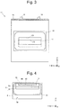
- Fig. 3 is a view of the plate-shaped member 11 when the plate-shaped member 11 is viewed from a -X direction in Fig. 1 .
- Fig. 4 is a view of the stage 5 and a sealing unit 6 when the stage 5 and the sealing unit 6 are viewed from the -X direction in Fig. 1 .
- Figs. 5 to 7 are main-part enlarged views illustrating the configuration relating to the closing of the communication unit 10.
- Fig. 5 illustrates a state in which the communication unit 10 is closed while the stage 5 is located on the side of the load lock chamber 2.
- Fig. 6 illustrates a middle state in which the stage 5 is moved from the side of the load lock chamber 2 to the side of the processing chamber 3.
- Fig. 7 illustrates a state in which the stage 5 is located on the side of the processing chamber 3.
- the plate-shaped member 11 is a tabular member larger than an opening (that is, an opening of the communication unit 10 in an inner wall 30 of the processing chamber 3, hereinafter also simply referred to as "an opening") 300 of the communication unit 10 on the side of the processing chamber 3, and is provided such that a main surface of the plate-shaped member 11 covers a region around the opening 300 from the side of the processing chamber 3.
- a horizontally extending turning shaft 12 is disposed on the inner wall 30 of the processing chamber 3 and above the opening 300.
- a hinge member 13 is rotatably disposed on the turning shaft 12, and an upper side of the plate-shaped member 11 is fixed to the hinge member 13 with a screw 14 or the like.
- the plate-shaped member 11 is provided so as to be switchable between a closed state (the state in Fig. 5 ) in which the plate-shaped member 11 abuts on the inner wall 30 and an open state (the state in Figs. 6 and 7 ) in which the plate-shaped member 11 is detached from the inner wall 30.
- the hinge member 13 is what is called a spring hinge in which an urging member (specifically, for example, a torsion spring) 15 is incorporated.
- the plate-shaped member 11 is always urged in the direction in which the plate-shaped member 11 is separated from the inner wall 30 of the processing chamber 3 (that is, in an opening direction) by the urging member 15 (arrow AR11).
- a restricting member 16 which restricts an angle formed by the plate-shaped member 11 and the inner wall 30 such that the angle is not larger than a predetermined angle, is provided on the inner wall 30 of the processing chamber 3 and below the opening 300.
- the restricting member 16 is a member having an L-shape section. When the angle formed by the plate-shaped member 11 and the inner wall 30 of the processing chamber 3 reaches the predetermined angle, the restricting member 16 is caught by a lower portion of the plate-shaped member 11 such that the angle is not larger than the predetermined angle (the state in Figs. 6 and 7 ).
- the predetermined angle is an angle at which a second opening end 172 (to be described later) is located at the same level as the stage 5 (specifically, the level of the horizontal plane on which the stage 5 is moved) when the angle formed by the plate-shaped member 11 and the inner wall 30 of the processing chamber 3 is the predetermined angle.
- the inclined portion 52 inclined at the same angle as the penetration opening 17 is formed at the base end of the stage 5, and the inclined portion 52 is disposed inside the penetration opening 17 while the stage 5 is located on the side of the load lock chamber 2 (the state in Fig. 5 ).
- the openings 300 of the communication unit 10 and the open ends (the first opening end 171 and the second opening end 172) of the penetration opening 17 have substantially the same shape and substantially the same size.
- a seal unit (first seal unit) 18 that seals a gap between the plate-shaped member 11 and the inner wall 30 is formed in the plate-shaped member 11.
- the first seal unit 18 is a bank-shaped projection surrounding the first opening end 171, and an entire circumference of the first seal unit 18 abuts on the inner wall 30 in a close contact state while collectively surrounding the opening 300 and the first opening end 171 when the plate-shaped member 11 is in the closed state.
- the sealing unit 6 is fixed to one end (base end) of the stage 5.
- a surface (hereinafter also referred to as "a sealing surface") 60 of the sealing unit 6 to which the base end of the stage 5 is attached has a size larger than the second opening end 172 of the penetration opening 17 formed in the plate-shaped member 11, and the sealing unit 6 does not enter the penetration opening 17.
- the sealing unit 6 abuts on the plate-shaped member 11 at a certain point of time when the stage 5 is moved to the side of the load lock chamber 2, the sealing unit 6 rotates the plate-shaped member 11 against the urging force of the urging member 15 (specifically, the spring force of the spring hinge) when the stage 5 is further moved, and finally the sealing unit 6 presses the plate-shaped member 11 against the inner wall 30 of the processing chamber 3 (that is, the plate-shaped member 11 is brought into the closed state).
- the urging force of the urging member 15 specifically, the spring force of the spring hinge
- a seal unit (third seal unit) 61 that seals a gap between the plate-shaped member 11 and the sealing surface 60 is formed in the sealing surface 60.
- the third seal unit 61 is a bank-shaped projection that can surround the second opening end 172, and the entire circumference of the third seal unit 61 abuts on the plate-shaped member 11 in the close contact state while surrounding the second opening end 172 when the stage 5 is disposed on the side of the load lock chamber 2.
- the door 22 is opened while the stage 5 is disposed on the side of the load lock chamber 2 (the state in Fig. 1 ).
- the stage 5 is disposed in the load lock chamber 2
- the inclined portion 52 of the stage 5 is disposed in the penetration opening 17
- the sealing unit 6 abuts on the plate-shaped member 11, and the plate-shaped member 11 is in the closed state.
- the gap between the plate-shaped member 11 and the inner wall 30 of the processing chamber 3 is sealed by the first seal unit 18 and the second seal unit 33, and the gap between the plate-shaped member 11 and the sealing surface 60 is sealed by the third seal unit 61. Consequently, the opening 300 of the communication unit 10 is closed.
- the vacuum in the processing chamber 3 will not be broken even if the door 22 is opened.
- the operator inserts the sample plate 9 on which the sample 90 is held from the insertion port 21, and places the sample plate 9 on the placement portion 51 of the stage 5.
- a sensor not illustrated or the like detects that the new sample plate 9 is placed on the stage 5
- the door 22 is closed, the insertion port 21 is closed, and the load lock chamber 2 becomes the sealed space.
- the valve 41 is opened while the vacuum pump 43 is driven. Consequently, the load lock chamber 2 is depressurized.
- the moving mechanism 7 starts to move the stage 5 on which the sample plate 9 is placed from the side of the load lock chamber 2 to the side of the processing chamber 3.
- the stage 5 starts to move, the plate-shaped member 11 that is in the closed state by the abutment of the sealing unit 6 is rotated by the urging force of the urging member 15 to separate from the inner wall 30 of the processing chamber 3.
- the angle formed by the plate-shaped member 11 and the inner wall 30 reaches the predetermined angle, the plate-shaped member 11 is caught by the restricting member 16, and the rotation of the plate-shaped member 11 is stopped.
- the stage 5 is further moved to the side of the processing chamber 3 and the sample plate 9 comes to a preset position in the processing chamber 3.
- the process of the sample plate 9 is started.
- a content of the process performed in the processing chamber 3 is as described above.
- the moving mechanism 7 starts to move the stage 5 on which the sample plate 9 is placed from the side of the processing chamber 3 to the side of the load lock chamber 2.
- the leading end of the stage 5 sequentially passes through the penetration opening 17 of the plate-shaped member 11 and the communication unit 10, and enters the load lock chamber 2.
- a posture of the plate-shaped member 11 is restricted by the restricting member 16 such that the second opening end 172 comes to the level at which the stage 5 is moved.
- the stage 5 can pass through the penetration opening 17 without being caught by the second opening end 172.
- the sealing unit 6 abuts on the plate-shaped member 11 when the stage 5 is moved by a certain distance.
- the plate-shaped member 11 is pushed by the sealing unit 6 to rotate against the urging force of the urging member 15.
- the plate-shaped member 11 abuts on the inner wall 30 of the processing chamber 3 to become the closed state. As described above, at this point, the opening 300 is closed.
- the vacuum in the load lock chamber 2 is broken and the door 22 is opened.
- the opening 300 is closed, so that the vacuum in the processing chamber 3 will not be broken even if the door 22 is opened.
- Fig. 8 is a view illustrating atmospheric force applied to the member of interest 80.
- magnitude of atmospheric force F2 pushing the member of interest 80 toward the side of the load lock chamber 2 is proportional to an area (an area viewed from side of the load lock chamber 2 toward the side of the processing chamber 3) A2 of the movable plate 73.
- the movable plate 73 is formed such that the area A2 of the movable plate 73 is larger than the area A1 of the opening 300.
- the magnitude of the atmospheric force F2 pushing the member of interest 80 toward the side of the load lock chamber 2 is larger than the atmospheric force F1 pushing the member of interest 80 toward the side of the processing chamber 3.
- a seal unit that seals the gap between the plate-shaped member 11 and the sealing unit 6 may be provided in the surface of the plate-shaped member 11 on the side of the sealing unit 6.
- the seal unit is a bank-shaped projection surrounding the second opening end 172, and an entire circumference of the seal unit abuts on the sealing surface 60 in the close contact state while surrounding the second opening end 172 when the sealing unit 6 abuts on the plate-shaped member 11.
- the third seal unit 61 may be omitted.
- the plate-shaped member 11 is not necessarily provided.
- Fig. 9 illustrates a configuration example in the case that the plate-shaped member 11 is not provided.
- the stage 5a is formed by a tabular member as a whole, and the inclined portion is not formed.
- a sealing surface 60a of the sealing unit 6a has a size larger than the opening 300 of the communication unit 10, and the sealing unit 6a does not enter the communication unit 10.
- a seal unit (fourth seal unit) 61a that seals a gap between the sealing surface 60a and the inner wall 30 of the processing chamber 3 is formed in the sealing surface 60a.
- the fourth seal unit 61a is a bank-shaped projection that can surround the opening 300, and the entire circumference of the fourth seal unit 61a abuts on the inner wall 30 in the close contact state while surrounding the opening 300 when the stage 5a is disposed on the side of the load lock chamber 2.
- a seal unit (a fifth seal unit) 33a that seals a gap between the inner wall 30 and the sealing unit 6a is also formed in the inner wall 30.
- the fifth seal unit 33a is a bank-like projection that surrounds the opening 300, and the entire circumference of the fifth seal unit 33a abuts on the sealing surface 60a in the close contact state while surrounding the opening 300 when the stage 5a is disposed in the load lock chamber 2.
- the fourth seal unit 61a and the fifth seal unit 33a are formed at positions in which the fourth seal unit 61a and the fifth seal unit 33a do not interfere with each other, and the fourth seal unit 61a and the fifth seal unit 33a are formed at the same level.
- one of the fourth seal unit 61a and the fifth seal unit 33a may be omitted.
- the urging member 15 that urges the plate-shaped member 11 in the opening direction is provided in the plate-shaped member 11, and the restricting member 16 that restricts the posture of the plate-shaped member 11 is provided.
- the urging member 15 and the restricting member 16 are not necessarily provided.
- an opening and closing switch that opens and closes the plate-shaped member 11 may be provided, and the controller 8 may control the opening and closing switch.
- the present invention is applied to the mass spectrometer.
- the present invention can also be applied to various vacuum processing apparatuses other than the mass spectrometer.
Landscapes
- Chemical & Material Sciences (AREA)
- Physics & Mathematics (AREA)
- Analytical Chemistry (AREA)
- Health & Medical Sciences (AREA)
- Life Sciences & Earth Sciences (AREA)
- Spectroscopy & Molecular Physics (AREA)
- Optics & Photonics (AREA)
- Engineering & Computer Science (AREA)
- Plasma & Fusion (AREA)
- Electrochemistry (AREA)
- Biochemistry (AREA)
- General Health & Medical Sciences (AREA)
- General Physics & Mathematics (AREA)
- Immunology (AREA)
- Pathology (AREA)
- Chemical Kinetics & Catalysis (AREA)
- Molecular Biology (AREA)
- Electron Tubes For Measurement (AREA)
- Other Investigation Or Analysis Of Materials By Electrical Means (AREA)
- Drying Of Semiconductors (AREA)
Abstract
Description
- The present invention relates to a vacuum processing apparatus that processes an object under vacuum. For example, the present invention relates to a mass spectrometer that performs mass spectrometry of a sample under vacuum.
- For example, a mass spectrometer, which ionizes a sample by irradiating the sample with a laser beam under vacuum, accelerates the ions to fly, and separates and detects the flying ions according to their mass-to-charge ratio, is known as a vacuum processing apparatus that processes an object under vacuum (for example, Patent Literature 1).
- In this type of apparatus, for example, a door between a processing chamber and the outside of the apparatus is opened to bring an object in the processing chamber, the door is closed to evacuate the processing chamber, and the object is processed. When the process is ended, the vacuum in the processing chamber is broken, and the door is opened to bring the object out of the processing chamber. However, in this manner, if the vacuum in the processing chamber is broken and the evacuation is performed each time the object is exchanged, it takes much time to replace objects in the processing chamber, and the throughput of the apparatus is very low.
- For this reason, sometimes a load lock chamber is provided between the processing chamber and the outside of the apparatus (for example, Patent Literature 2). In the apparatus of
Patent Literature 2, a door (first door) separating the outside of the apparatus from the load lock chamber is opened, the object is brought in the load lock chamber, and the load lock chamber is evacuated. When the load lock chamber reaches a preset degree of vacuum, another door (second door) separating the load lock chamber from the processing chamber (which is maintained at the preset degree of vacuum) is opened. Specifically, the second door is constructed with a gate valve. When the second door is opened, a transfer robot disposed in the processing chamber extends an extensible arm to enter a hand to the load lock chamber, grips the object in the load lock chamber, shrinks the arm to return the hand to the processing chamber, and transfers the object to the processing chamber. When the arm retreats from the load lock chamber, the second door is closed and the object is processed in the processing chamber. When the process on the object is ended, the second door is opened. The transfer robot grips the processed object existing in the processing chamber with the hand, advances the hand into the load lock chamber to transfer the object to the load lock chamber, and places the object at a predetermined position in the load lock chamber. Then, after the arm of the transfer robot retreats from the load lock chamber, the second door is closed. When the second door is closed to separate the processing chamber and the load lock chamber, the load lock chamber is opened to the atmosphere, and the object is brought out from the apparatus. - Normally, the size of the load lock chamber is made minimum for exchanging the object with the outside of the apparatus. Thus, the internal volume of the load lock chamber is smaller than the internal volume of the processing chamber in which the equipment or the like necessary for process is disposed. When the load lock chamber is provided in the apparatus, it is only necessary, in exchanging the object, to evacuate the load lock chamber alone which has relatively smaller internal volume, and the necessity of evacuating the processing chamber having a relatively larger internal volume is reduced.
-
- Patent Literature 1:
U. S. Patent No. 8872103 - Patent Literature 2:
JP 2012-015331 A - When the load lock chamber is provided in the apparatus, the following disadvantage arises while the above advantage is obtained. In the case that the load lock chamber is not provided, the operation to transfer the object between the outside of the apparatus and the processing chamber is enough, but in the case that the load lock chamber is provided, it is necessary to perform operations: to transfer the object between the outside of the apparatus and the load lock chamber; to transfer the object between the load lock chamber and the processing chamber; and to separate the load lock chamber from the processing chamber (these operations are hereinafter simply referred to as an exchange operation). For example, in
Patent Literature 2, as described above, the exchange operation is performed by such a series of operations that the second door is opened, the transfer robot advances the hand gripping the processed object into the load lock chamber and transfers the object to the load lock chamber, and the second door is closed after the arm of the transfer robot retreats from the load lock chamber. In this case, time necessary for the exchange operation is a sum of a movement time of the arm and an opening and closing time of the door. - A problem to be solved by the present invention is to provide a technique capable of suppressing the time necessary for the exchange operation between the load lock chamber and the processing chamber in a short time in the apparatus configuration including the load lock chamber.
- According to one aspect of the present invention, a vacuum processing apparatus includes: a processing chamber that can bring an inside of the processing chamber into a vacuum state; a load lock chamber that is coupled to the processing chamber and that is switchable between an atmospheric state and the vacuum state; a communication unit configured to communicate the processing chamber with the load lock chamber; a stage on which a processing object is placed, the stage being movable between the processing chamber and the load lock chamber through the communication unit; and a sealing unit fixed to the stage, the sealing unit being larger than an opening of the communication unit on a processing chamber side.
- Before processing, the processing object is brought from the outside into the load lock chamber, and placed on the stage while the stage is located on the load lock chamber side. At this point, the opening of the communication unit on the processing chamber side is sealed by the sealing unit fixed to the stage. Thus, the processing chamber is not open to the atmosphere. After the load lock chamber is switched from the atmospheric state to the vacuum state, the stage on which the object is placed is moved from the load lock chamber to the processing chamber, and the object is transferred to the processing chamber. Then, the process on the object placed on the stage is performed under vacuum in the processing chamber. When the process is ended in the processing chamber, the stage on which the processed object is placed is moved from the processing chamber to the load lock chamber side, and the object is transferred to the load lock chamber. When the stage is disposed on the load lock chamber side, the opening of the communication unit on the processing chamber side is sealed by the sealing unit again. At this point, the load lock chamber is opened to the atmosphere, and the object on the stage is brought out to the outside of the apparatus.
- In this way, in this aspect, the position of the stage interlocks with the closing and opening of the communication unit, and the load lock chamber and the processing chamber are naturally separated from each other when the object is transferred from the processing chamber to the load lock chamber. Thus, the time necessary for the exchange operation between the load lock chamber and the processing chamber can be shortened.
- Additionally, in this aspect, the closing and opening operation of the communication unit interlocks with the moving operation of the object, so that the number of components of the apparatus can be decreased, which reduces the manufacturing cost of the apparatus.
- Additionally, in this aspect, the configuration that closes and opens the communication unit can be simplified, so that the volume of the load lock chamber can be kept small. Consequently, the time necessary for the evacuation of the load lock chamber can be shortened (for example, several seconds).
- Preferably, the vacuum processing apparatus includes:
- a plate-shaped member rotatably provided on a horizontal axis placed above the opening of the communication unit on the processing chamber side in an inner wall of the processing chamber, the plate-shaped member being switchable between a closed state in which the plate-shaped member abuts on the inner wall and an opened state in which the plate-shaped member is detached from the inner wall; and
- a penetration opening formed in the plate-shaped member to allow the stage to pass. An opening end of the penetration opening on the inner wall side is formed at a position corresponding to the opening of the communication unit on the processing chamber side when the plate-shaped member is in the closed state, while the penetration opening is inclined obliquely downward as the penetration opening goes away from the inner wall, an inclined portion inclined obliquely downward at an angle equal to that of the penetration opening is formed at an end of the stage on a side on which the sealing unit is fixed as it approaches the sealing unit, the sealing unit is larger than an opening end of the penetration opening on a side opposite to the inner wall, and in a state in which the stage is located on a load lock chamber side, the inclined portion of the stage is disposed inside the penetration opening, and the sealing unit abuts on the plate-shaped member to bring the plate-shaped member into the closed state.
- In this aspect, the opening on the processing chamber side of the communication unit is sealed by the sealing unit with the plate-shaped member interposed between them while the stage is located on the load lock chamber side. At this point, the penetration opening of the plate-shaped member is obliquely formed, and corresponding to this, the inclined portion is formed at the base end of the stage. For this reason, the position of the sealing unit with respect to the top surface of the stage can be lowered by the inclination of the inclined portion. According to this aspect, even if some sort of component or the like is disposed close to the top surface of the stage due to a layout of the processing chamber, interference between the component and the sealing unit can be avoided.
- For example, in the mass spectrometer that is a kind of the vacuum processing apparatus, an electrode ("an extraction electrode") that extracts a substance ionized by irradiating the object (sample) on the stage with a laser beam is provided at a position very close to the object on the stage (for example, the position at which a separation distance from the object is about 3 mm). In this case, if a portion projecting higher than the top surface of the stage exists in the sealing unit fixed to the stage, the portion may interfere with the extraction electrode. According to the above aspect, the portion projecting higher than the top surface of the stage is hardly formed because the position of the sealing unit can be lowered.
- Preferably, the vacuum processing apparatus further includes: a urging member that urges the plate-shaped member in a direction in which the plate-shaped member is detached from the inner wall of the processing chamber; and a restricting member that restricts an angle formed by the plate-shaped member and the inner wall of the processing chamber such that the angle is not larger than a predetermined angle. When the angle formed by the plate member and the inner wall of the processing chamber is at the predetermined angle, the opening end of the penetration opening on the opposite side to the inner wall is located at the same level as that of the stage.
- In this aspect, the plate-shaped member is urged in a direction in which the plate-shaped member is detached from the inner wall of the processing chamber by the urging member, so that the plate-shaped member automatically becomes an open state when the sealing unit is separated from the plate-shaped member (that is, when the stage starts to move from the load lock chamber to the processing chamber).When the plate-shaped member rotates by the predetermined angle, the plate-shaped member is restricted by the restricting member so as not to further rotate. The opening end of the plate-shaped member on the opposite side to the inner wall in the penetration opening is located at the same level as the stage while the plate-shaped member is being restricted by the restricting member. Thus, when moving from the processing chamber to the load lock chamber, the stage can pass through the penetration opening without being caught by the opening end.
- Preferably, the vacuum processing apparatus further includes a moving mechanism that moves the stage. The moving mechanism includes: a base member coupled to the sealing unit; a first guide rail that guides the base member in the processing chamber; a connecting rod coupled to the base member at one end, the connecting rod being inserted in a hole made in a sidewall of the processing chamber, the other end being disposed outside the processing chamber; a movable plate coupled to the other end of the connecting rod; a second guide rail that guides the movable plate; and a bellows disposed between the movable plate and the sidewall, the bellows following displacement of the movable plate while airtightness of the processing chamber is maintained. The movable plate is larger than the opening of the communication unit on the processing chamber side when viewed from the load lock chamber side toward the processing chamber side.
- It is supposed here that the sealing unit, the base member, the connecting rod, and the movable plate are considered as one member, and this member is referred to as a member of interest. When the stage is placed in the load lock chamber in the atmospheric state, magnitude of atmospheric force pushing the member of interest toward the processing chamber side with the plate-shaped member interposed between them is proportional to the area of the opening of the communication unit on the processing chamber side. On the other hand, magnitude of atmospheric force pushing the member of interest toward the load lock chamber side is proportional to the area of the movable plate (an area viewed along a horizontal direction). According to the configuration in which the movable plate is larger than the opening of the communication unit as viewed from the load lock chamber side toward the processing chamber side, even if driving force of the moving mechanism is lost while the stage is placed in the load lock chamber in the atmospheric state, the member of interest is pressed against the load lock chamber side, and the divided state of the load lock chamber and the processing chamber is maintained. That is, even if the driving force of the moving mechanism is lost due to an unexpected situation such as a power failure, the sealing of the processing chamber is assured so as not to be broken.
- Since the opening of the communication unit on the processing chamber side is sealed by the sealing unit fixed to the stage when the stage is in the load lock chamber, the load lock chamber and the processing chamber are automatically separated from each other when the object is transferred from the processing chamber to the load lock chamber. Thus, the time necessary for the exchange operation between the load lock chamber and the processing chamber can be shortened.
-
-
Fig. 1 is a longitudinal sectional view illustrating a part of a mass spectrometer, and is a view illustrating a state in which a stage is located on a load lock chamber side. -
Fig. 2 is a longitudinal sectional view illustrating a part of the mass spectrometer, and is a view illustrating a state in which the stage is located on a processing chamber side. -
Fig. 3 is a view of a plate-shaped member when the plate-shaped member is viewed from a -X direction inFig. 1 . -
Fig. 4 is a view of the stage and a sealing unit when the stage and the sealing unit are viewed from the -X direction inFig. 1 . -
Fig. 5 is a main-part enlarged view illustrating a configuration relating to closing of a communication unit. -
Fig. 6 is another main-part enlarged view illustrating the configuration relating to the closing of the communication unit. -
Fig. 7 is still another main-part enlarged view illustrating the configuration relating to the closing of the communication unit. -
Fig. 8 is a view illustrating atmospheric force applied to a member of interest. -
Fig. 9 is a main-part enlarged view illustrating a configuration relating to closing of a communication unit according to another embodiment. - Hereinafter, preferred embodiments of the present invention will be described with reference to the drawings.
-
Figs. 1 and2 are longitudinal sectional views illustrating a part of a mass spectrometer 1 that is an example of a vacuum processing apparatus.Fig. 1 illustrates a state in which astage 5 is located on a side of aload lock chamber 2, andFig. 2 illustrates a state in which thestage 5 is located on a side of aprocessing chamber 3. - The mass spectrometer 1 is a device that irradiates an object (sample 90 (see
Fig. 4 )) with a laser beam under vacuum to perform ionization, and separates and detects flying ions according to a mass-to-charge ratio. Thesample 90 is held on asample plate 9. Specifically, thesample plate 9 is a plate-shaped member, and a plurality ofrecesses 91 are formed on a top surface of thesample plate 9. Thesample 90 is dropped onto each of the plurality ofrecesses 91, whereby thesample 90 is held on the sample plate 9 (seeFig. 4 ). - The mass spectrometer 1 includes the
load lock chamber 2 in which thesample plate 9 is exchanged between the outside of the apparatus and theprocessing chamber 3, theprocessing chamber 3 in which a process is performed on thesample 90 held by thesample plate 9, and anevacuation system 4 that independently evacuates theload lock chamber 2 and theprocessing chamber 3. Theload lock chamber 2 and theprocessing chamber 3 are connected to each other, and acommunication unit 10 that communicates theload lock chamber 2 and theprocessing chamber 3 is formed between theload lock chamber 2 and theprocessing chamber 3. The mass spectrometer 1 also includes thestage 5 on which thesample plate 9 is placed, asealing unit 6 fixed to thestage 5, and a movingmechanism 7 that moves thestage 5. The mass spectrometer 1 also includes acontroller 8 that controls each unit of the mass spectrometer 1 to cause the unit to perform a series of processes on thesample plate 9. - As described above, the
load lock chamber 2 is a chamber in which thesample plate 9 is exchanged between the outside of the apparatus and theprocessing chamber 3, and has a minimum size necessary for exchanging thesample plate 9. Specifically, theload lock chamber 2 is formed such that the internal volume of theload lock chamber 2 becomes the minimum size that can accommodate aplacement portion 51 of thesample plate 9 in thestage 5. Hereinafter, the state in which thestage 5 is located on the side of theload lock chamber 2 means a state in which theentire placement portion 51 of thesample plate 9 is disposed in theload lock chamber 2. - The
load lock chamber 2 includes aninsertion port 21 of thesample plate 9 and adoor 22 that opens and closes theinsertion port 21. A leading end of thestage 5 reaches a vicinity of theinsertion port 21 while thestage 5 is located on the side of theload lock chamber 2. At this point, an operator can insert thesample plate 9 from theinsertion port 21, and places thesample plate 9 on theplacement portion 51 of thestage 5. - The
load lock chamber 2 is connected to avacuum pump 43 through a pipe in which thevalve 41 is inserted. When thecommunication unit 10 is closed while thedoor 22 is closed, theload lock chamber 2 becomes a sealed space. At this point, when thevalve 41 is opened while thevacuum pump 43 is driven, theload lock chamber 2 is brought into a vacuum state. - A process, in which the
sample 90 held on thesample plate 9 of thestage 5 is ionized by irradiating thesample 90 with the laser beam from a laser beam source (not illustrated) and an ionized substance is extracted by anextraction electrode 31, is performed in theprocessing chamber 3 under vacuum. However, as described above, thesample 90 is held in each of the plurality ofrecesses 91 in thesample plate 9. In order to sequentially irradiate thesample 90 held in eachrecess 91 with the laser beam, the above process is performed while the movingmechanism 7 moves thestage 5 in theprocessing chamber 3 with respect to the laser beam source. The substance extracted by theextraction electrode 31 is accelerated, separated according to the mass-to-charge ratio, and detected (a configuration relating to the separation and the detection is not illustrated). - When the ionized substance is extracted by the
extraction electrode 31, a pulsed high voltage of several kilovolts is applied to theextraction electrode 31 in order to form a preset electric field gradient between theextraction electrode 31 and thesample plate 9. It is necessary to increase the voltage applied to theextraction electrode 31. Enlargement of a power supply with increasing separation distance between thesample plate 9 and theextraction electrode 31, and improvement of a withstanding voltage of components relating to voltage supply, and the like are required when the large voltage is applied to theextraction electrode 31. Due to such circumstances, it is preferable that theextraction electrode 31 is located at a position very close to the sample plate 9 (preferably a position where the separation distance from thesample plate 9 is several millimeters). For this reason, in the mass spectrometer 1, theextraction electrode 31 is disposed such that a lower end of theextraction electrode 31 is located at a position separated by a sufficiently small distance (for example, 3 mm) from a horizontal plane through which the top surface of thesample plate 9 placed on thestage 5 passes. - The
processing chamber 3 is connected to thevacuum pump 43 through a pipe in which avalve 42 is inserted. When thecommunication unit 10 is closed, theprocessing chamber 3 becomes the sealed space. At this point, when thevalve 42 is opened while thevacuum pump 43 is driven, theprocessing chamber 3 becomes the vacuum state, and the above process can be performed. However, as will become clear later, theprocessing chamber 3 is maintained at a preset degree of vacuum during the successive process of a plurality ofsample plates 9, but theprocessing chamber 3 is not evacuated each time thesample plate 9 is exchanged. - The
stage 5 is a member on which thesample plate 9 is placed. Specifically, theplacement portion 51 that is a flat region where thesample plate 9 is placed is formed at one end (leading end) of thestage 5. The other end (base end) of thestage 5 is coupled to the movingmechanism 7 with the sealingunit 6 interposed between them, and theplacement portion 51 becomes horizontal in this coupled state. - The base end of the
stage 5 is fixed to thesealing unit 6, and aninclined portion 52 inclined obliquely downward toward the sealingunit 6 is formed in the base end. This corresponds to the fact that apenetration opening 17 of a plate-shaped member 11 (to be described later) is formed while inclined, and an inclination angle of theinclined portion 52 is identical to an inclination angle of thepenetration opening 17. - The moving
mechanism 7 is a mechanism that moves thestage 5 in a horizontal plane (specifically, in the X direction (in which theload lock chamber 2 and theprocessing chamber 3 are disposed) and a Y direction). The movingmechanism 7 is the mechanism that moves thestage 5 between theprocessing chamber 3 and theload lock chamber 2 through thecommunication unit 10, and is the mechanism that moves thestage 5 in theprocessing chamber 3 as described above (that is, moves thestage 5 relative to the laser beam source). - The moving
mechanism 7 includes abase member 71 coupled to thesealing unit 6. Thebase member 71 is fixed on alinear block 713 that is disposed on aY guide rail 712 laid in the Y direction in theprocessing chamber 3. TheY guide rail 712 is fixed on alinear block 715 that is disposed on an X guide rail (first guide rail) 714 laid in the X direction in theprocessing chamber 3. TheX guide rail 714 and theY guide rail 712 are laid so as to extend horizontally, and theX guide rail 714 and theY guide rail 712 are assured such that theplacement portion 51 of thestage 5 coupled to thebase member 71 with the sealingunit 6 interposed between them moves within a horizontal plane. - The
base member 71 is fixed to one end of a connectingrod 72. The connectingrod 72 is inserted in ahole 31 made in a sidewall of theprocessing chamber 3, and the other end of the connectingrod 72 is coupled to amovable plate 73 disposed outside theprocessing chamber 3. Themovable plate 73 has a size lager than anopening 300 of thecommunication unit 10 on the side of theprocessing chamber 3 when viewed from the side of theload lock chamber 2 toward the side of theprocessing chamber 3. - A space between the
movable plate 73 and the outer wall of theprocessing chamber 3 is sealed by abellows 74. That is, one end of thebellows 74 is bonded to the outer wall of theprocessing chamber 3 while the other end is bonded to themovable plate 73, and thebellows 74 follows displacement of themovable plate 73 while airtightness of theprocessing chamber 3 is maintained. -
A Y actuator 731 that moves themovable plate 73 along the Y direction is connected to themovable plate 73. Themovable plate 73 and theY actuator 731 are disposed on anX stage 733 mounted on an X guide rail (second guide rail) 732 laid in the X direction. AnX actuator 734 that moves theX stage 733 along the X direction is connected to theX stage 733. The Y actuator 731, thesecond guide rail 732, theX stage 733, and theX actuator 734 are disposed outside theprocessing chamber 3. However, thefirst guide rail 714 and thesecond guide rail 732 are preferably disposed on acommon base 70 in order to easily assure mutual position accuracy. For example, a ball screw drive method, a linear motor drive method, or a belt drive method can be adopted as theX actuator 734 and theY actuator 731. - In the mass spectrometer 1, the
communication unit 10 is closed when thestage 5 is disposed in theload lock chamber 2. The configuration relating to the closing of thecommunication unit 10 will be described with reference toFigs. 3 to 7 , in addition toFigs. 1 and2 .Fig. 3 is a view of the plate-shapedmember 11 when the plate-shapedmember 11 is viewed from a -X direction inFig. 1 .Fig. 4 is a view of thestage 5 and asealing unit 6 when thestage 5 and thesealing unit 6 are viewed from the -X direction inFig. 1 .Figs. 5 to 7 are main-part enlarged views illustrating the configuration relating to the closing of thecommunication unit 10.Fig. 5 illustrates a state in which thecommunication unit 10 is closed while thestage 5 is located on the side of theload lock chamber 2.Fig. 6 illustrates a middle state in which thestage 5 is moved from the side of theload lock chamber 2 to the side of theprocessing chamber 3.Fig. 7 illustrates a state in which thestage 5 is located on the side of theprocessing chamber 3. - The plate-shaped
member 11 is a tabular member larger than an opening (that is, an opening of thecommunication unit 10 in aninner wall 30 of theprocessing chamber 3, hereinafter also simply referred to as "an opening") 300 of thecommunication unit 10 on the side of theprocessing chamber 3, and is provided such that a main surface of the plate-shapedmember 11 covers a region around the opening 300 from the side of theprocessing chamber 3. Specifically, a horizontally extending turningshaft 12 is disposed on theinner wall 30 of theprocessing chamber 3 and above theopening 300. Ahinge member 13 is rotatably disposed on the turningshaft 12, and an upper side of the plate-shapedmember 11 is fixed to thehinge member 13 with ascrew 14 or the like. Consequently, the plate-shapedmember 11 is provided so as to be switchable between a closed state (the state inFig. 5 ) in which the plate-shapedmember 11 abuts on theinner wall 30 and an open state (the state inFigs. 6 and7 ) in which the plate-shapedmember 11 is detached from theinner wall 30. - The
hinge member 13 is what is called a spring hinge in which an urging member (specifically, for example, a torsion spring) 15 is incorporated. The plate-shapedmember 11 is always urged in the direction in which the plate-shapedmember 11 is separated from theinner wall 30 of the processing chamber 3 (that is, in an opening direction) by the urging member 15 (arrow AR11). - A restricting
member 16, which restricts an angle formed by the plate-shapedmember 11 and theinner wall 30 such that the angle is not larger than a predetermined angle, is provided on theinner wall 30 of theprocessing chamber 3 and below theopening 300. For example, the restrictingmember 16 is a member having an L-shape section. When the angle formed by the plate-shapedmember 11 and theinner wall 30 of theprocessing chamber 3 reaches the predetermined angle, the restrictingmember 16 is caught by a lower portion of the plate-shapedmember 11 such that the angle is not larger than the predetermined angle (the state inFigs. 6 and7 ). Specifically, the predetermined angle is an angle at which a second opening end 172 (to be described later) is located at the same level as the stage 5 (specifically, the level of the horizontal plane on which thestage 5 is moved) when the angle formed by the plate-shapedmember 11 and theinner wall 30 of theprocessing chamber 3 is the predetermined angle. - The
penetration opening 17 through which thestage 5 passes is formed in the plate-shapedmember 11. Thepenetration opening 17 is formed obliquely downwardly as going away from theinner wall 30 of theprocessing chamber 3, and the opening end (second opening end) 172 opened to a surface on the opposite side to theinner wall 30 is formed at a position lower than an opening end (first opening end) 171 opened to a surface opposed to theinner wall 30. However, the first openingend 171 is formed at a position corresponding to the opening 300 (specifically, a position overlapping the opening 300) when the plate-shapedmember 11 is in the closed state. Thus, thesecond opening end 172 is disposed at a position lower than theopening 300. As described above, theinclined portion 52 inclined at the same angle as thepenetration opening 17 is formed at the base end of thestage 5, and theinclined portion 52 is disposed inside thepenetration opening 17 while thestage 5 is located on the side of the load lock chamber 2 (the state inFig. 5 ). - In the embodiment, the
openings 300 of thecommunication unit 10 and the open ends (the first openingend 171 and the second opening end 172) of thepenetration opening 17 have substantially the same shape and substantially the same size. - A seal unit (first seal unit) 18 that seals a gap between the plate-shaped
member 11 and theinner wall 30 is formed in the plate-shapedmember 11. Specifically, thefirst seal unit 18 is a bank-shaped projection surrounding the first openingend 171, and an entire circumference of thefirst seal unit 18 abuts on theinner wall 30 in a close contact state while collectively surrounding theopening 300 and the first openingend 171 when the plate-shapedmember 11 is in the closed state. - In the embodiment, a seal unit (second seal unit) 33 that seals a gap between the plate-shaped
member 11 and theinner wall 30 is also formed in theinner wall 30. Specifically, thesecond seal unit 33 is a bank-like projection surrounding theopening 300, and an entire circumference of thesecond seal unit 33 abuts on the plate-shapedmember 11 in the close contact state while collectively surrounding theopening 300 and the first openingend 171 when the plate-shapedmember 11 is in the closed state. Thefirst seal unit 18 and thesecond seal unit 33 are formed at positions in which thefirst seal unit 18 and thesecond seal unit 33 do not interfere with each other, and thefirst seal unit 18 and thesecond seal unit 33 are formed at the same level. However, one of thefirst seal unit 18 and thesecond seal unit 33 may be omitted. - As described above, the sealing
unit 6 is fixed to one end (base end) of thestage 5. A surface (hereinafter also referred to as "a sealing surface") 60 of thesealing unit 6 to which the base end of thestage 5 is attached has a size larger than thesecond opening end 172 of thepenetration opening 17 formed in the plate-shapedmember 11, and thesealing unit 6 does not enter thepenetration opening 17. Thus, the sealingunit 6 abuts on the plate-shapedmember 11 at a certain point of time when thestage 5 is moved to the side of theload lock chamber 2, the sealingunit 6 rotates the plate-shapedmember 11 against the urging force of the urging member 15 (specifically, the spring force of the spring hinge) when thestage 5 is further moved, and finally thesealing unit 6 presses the plate-shapedmember 11 against theinner wall 30 of the processing chamber 3 (that is, the plate-shapedmember 11 is brought into the closed state). - A seal unit (third seal unit) 61 that seals a gap between the plate-shaped
member 11 and the sealingsurface 60 is formed in the sealingsurface 60. Specifically, thethird seal unit 61 is a bank-shaped projection that can surround thesecond opening end 172, and the entire circumference of thethird seal unit 61 abuts on the plate-shapedmember 11 in the close contact state while surrounding thesecond opening end 172 when thestage 5 is disposed on the side of theload lock chamber 2. - As described above, the
inclined portion 52 inclined at the same angle as the penetration opening 17 of the plate-shapedmember 11 is formed at the base end of thestage 5, and the position of thesealing unit 6 is lower than the top surface of thestage 5 by the inclination of theinclined portion 52. Consequently, the sealingunit 6 is assured so as not to interfere with theextraction electrode 31. - Operation of the mass spectrometer 1 will be described below with reference to
Figs. 1 to 7 . A series of operation described below is performed under the control of thecontroller 8. - In the state in which the mass spectrometer 1 is ready to receive the
new sample plate 9, thedoor 22 is opened while thestage 5 is disposed on the side of the load lock chamber 2 (the state inFig. 1 ). When thestage 5 is disposed in theload lock chamber 2, theinclined portion 52 of thestage 5 is disposed in thepenetration opening 17, the sealingunit 6 abuts on the plate-shapedmember 11, and the plate-shapedmember 11 is in the closed state. At this point, the gap between the plate-shapedmember 11 and theinner wall 30 of theprocessing chamber 3 is sealed by thefirst seal unit 18 and thesecond seal unit 33, and the gap between the plate-shapedmember 11 and the sealingsurface 60 is sealed by thethird seal unit 61. Consequently, theopening 300 of thecommunication unit 10 is closed. Thus, the vacuum in theprocessing chamber 3 will not be broken even if thedoor 22 is opened. - When the
door 22 is opened, the operator inserts thesample plate 9 on which thesample 90 is held from theinsertion port 21, and places thesample plate 9 on theplacement portion 51 of thestage 5. When a sensor (not illustrated) or the like detects that thenew sample plate 9 is placed on thestage 5, thedoor 22 is closed, theinsertion port 21 is closed, and theload lock chamber 2 becomes the sealed space. Then, thevalve 41 is opened while thevacuum pump 43 is driven. Consequently, theload lock chamber 2 is depressurized. - When the
load lock chamber 2 becomes a preset vacuum state, the movingmechanism 7 starts to move thestage 5 on which thesample plate 9 is placed from the side of theload lock chamber 2 to the side of theprocessing chamber 3. When thestage 5 starts to move, the plate-shapedmember 11 that is in the closed state by the abutment of thesealing unit 6 is rotated by the urging force of the urgingmember 15 to separate from theinner wall 30 of theprocessing chamber 3. When the angle formed by the plate-shapedmember 11 and theinner wall 30 reaches the predetermined angle, the plate-shapedmember 11 is caught by the restrictingmember 16, and the rotation of the plate-shapedmember 11 is stopped. Then, thestage 5 is further moved to the side of theprocessing chamber 3 and thesample plate 9 comes to a preset position in theprocessing chamber 3. At this point, the process of thesample plate 9 is started. A content of the process performed in theprocessing chamber 3 is as described above. - When the process of the
sample plate 9 is completed, the movingmechanism 7 starts to move thestage 5 on which thesample plate 9 is placed from the side of theprocessing chamber 3 to the side of theload lock chamber 2. The leading end of thestage 5 sequentially passes through the penetration opening 17 of the plate-shapedmember 11 and thecommunication unit 10, and enters theload lock chamber 2. As described above, a posture of the plate-shapedmember 11 is restricted by the restrictingmember 16 such that thesecond opening end 172 comes to the level at which thestage 5 is moved. Thus, thestage 5 can pass through thepenetration opening 17 without being caught by thesecond opening end 172. - The sealing
unit 6 abuts on the plate-shapedmember 11 when thestage 5 is moved by a certain distance. When thestage 5 is further moved, the plate-shapedmember 11 is pushed by the sealingunit 6 to rotate against the urging force of the urgingmember 15. When thestage 5 is completely disposed on the side of theload lock chamber 2, the plate-shapedmember 11 abuts on theinner wall 30 of theprocessing chamber 3 to become the closed state. As described above, at this point, theopening 300 is closed. - After the
stage 5 is disposed on the side of theload lock chamber 2, the vacuum in theload lock chamber 2 is broken and thedoor 22 is opened. As described above, when thestage 5 is located on the side of theload lock chamber 2, theopening 300 is closed, so that the vacuum in theprocessing chamber 3 will not be broken even if thedoor 22 is opened. When the operator takes out thesample plate 9 through theinsertion port 21, the mass spectrometer 1 returns to the state in which the mass spectrometer 1 can receive thenew sample plate 9. - The case that driving force of the moving
mechanism 7 is lost due to an unexpected situation such as a power failure while thestage 5 is disposed in theload lock chamber 2 in an atmospheric state in the mass spectrometer 1 will be described with reference toFigs. 1 and8 . In the following description, the sealingunit 6, thebase member 71, the connectingrod 72, and themovable plate 73 are regarded as one member, and this member is referred to as "a member ofinterest 80".Fig. 8 is a view illustrating atmospheric force applied to the member ofinterest 80. - It is assumed that the
load lock chamber 2 is in an atmospheric state, that theprocessing chamber 3 is in a vacuum state, and that thestage 5 is disposed on the side of the load lock chamber 2 (the state inFig. 1 ). At this point, magnitude of atmospheric force F1 pushing the member ofinterest 80 toward the side of theprocessing chamber 3 with the plate-shapedmember 11 interposed between them is proportional to an area (an area viewed from side of theload lock chamber 2 toward the side of the processing chamber 3) A1 of theopening 300 of thecommunication unit 10 on the side of theprocessing chamber 3. On the other hand, magnitude of atmospheric force F2 pushing the member ofinterest 80 toward the side of theload lock chamber 2 is proportional to an area (an area viewed from side of theload lock chamber 2 toward the side of the processing chamber 3) A2 of themovable plate 73. - At this point, the
movable plate 73 is formed such that the area A2 of themovable plate 73 is larger than the area A1 of theopening 300. Thus, the magnitude of the atmospheric force F2 pushing the member ofinterest 80 toward the side of theload lock chamber 2 is larger than the atmospheric force F1 pushing the member ofinterest 80 toward the side of theprocessing chamber 3. For this reason, even if the driving force of the movingmechanism 7 is lost, the member ofinterest 80 is maintained in the state in which the member ofinterest 80 is pressed against the side of theload lock chamber 2 by the atmospheric force. That is, the state in which theload lock chamber 2 and theprocessing chamber 3 are separated is maintained. As described above, in the mass spectrometer 1, even if the driving force of the movingmechanism 7 is lost due to the unexpected situation such as the power failure when theload lock chamber 2 is in the atmospheric state, the sealing of theprocessing chamber 3 is assured not so as not to be broken. - In the above embodiment, a seal unit that seals the gap between the plate-shaped
member 11 and thesealing unit 6 may be provided in the surface of the plate-shapedmember 11 on the side of thesealing unit 6. Specifically, the seal unit is a bank-shaped projection surrounding thesecond opening end 172, and an entire circumference of the seal unit abuts on the sealingsurface 60 in the close contact state while surrounding thesecond opening end 172 when thesealing unit 6 abuts on the plate-shapedmember 11. In the case that the seal unit is provided, thethird seal unit 61 may be omitted. - In the above embodiment, the plate-shaped
member 11 is not necessarily provided.Fig. 9 illustrates a configuration example in the case that the plate-shapedmember 11 is not provided. In this case, thestage 5a is formed by a tabular member as a whole, and the inclined portion is not formed. A sealingsurface 60a of thesealing unit 6a has a size larger than theopening 300 of thecommunication unit 10, and thesealing unit 6a does not enter thecommunication unit 10. A seal unit (fourth seal unit) 61a that seals a gap between the sealingsurface 60a and theinner wall 30 of theprocessing chamber 3 is formed in the sealingsurface 60a. Specifically, thefourth seal unit 61a is a bank-shaped projection that can surround theopening 300, and the entire circumference of thefourth seal unit 61a abuts on theinner wall 30 in the close contact state while surrounding theopening 300 when thestage 5a is disposed on the side of theload lock chamber 2. - Preferably, a seal unit (a fifth seal unit) 33a that seals a gap between the
inner wall 30 and thesealing unit 6a is also formed in theinner wall 30. Specifically, thefifth seal unit 33a is a bank-like projection that surrounds theopening 300, and the entire circumference of thefifth seal unit 33a abuts on the sealingsurface 60a in the close contact state while surrounding theopening 300 when thestage 5a is disposed in theload lock chamber 2. Thefourth seal unit 61a and thefifth seal unit 33a are formed at positions in which thefourth seal unit 61a and thefifth seal unit 33a do not interfere with each other, and thefourth seal unit 61a and thefifth seal unit 33a are formed at the same level. However, one of thefourth seal unit 61a and thefifth seal unit 33a may be omitted. - In the above embodiment, the urging
member 15 that urges the plate-shapedmember 11 in the opening direction is provided in the plate-shapedmember 11, and the restrictingmember 16 that restricts the posture of the plate-shapedmember 11 is provided. However, the urgingmember 15 and the restrictingmember 16 are not necessarily provided. For example, an opening and closing switch that opens and closes the plate-shapedmember 11 may be provided, and thecontroller 8 may control the opening and closing switch. - In the above embodiment, the present invention is applied to the mass spectrometer. However, the present invention can also be applied to various vacuum processing apparatuses other than the mass spectrometer.
-
- 1
- Mass spectrometer
- 2
- Load lock chamber
- 3
- Processing chamber
- 4
- Evacuation system
- 5
- Stage
- 6
- Sealing unit
- 7
- Moving mechanism
- 8
- Controller
- 9
- Sample plate
- 10
- Communication unit
- 11
- Plate-shaped member
- 12
- Turning shaft
- 13
- Hinge member
- 15
- Urging member
- 16
- Restricting member
- 17
- Penetration opening
- 18
- First seal unit
- 33
- Second seal unit
- 51
- Placement portion
- 52
- Inclined portion
- 60
- Sealing surface
- 61
- Third seal unit
- 71
- Base member
- 72
- Connecting rod
- 73
- Movable plate
- 74
- Bellows
- 171
- First opening end of the plate-shaped member
- 172
- Second opening end of the plate-shaped member
- 300
- Opening of the communication unit
Claims (5)
- A vacuum processing apparatus comprising:a processing chamber that can bring an inside of the processing chamber into a vacuum state;a load lock chamber that is coupled to the processing chamber and that is switchable between an atmospheric state and the vacuum state;a communication unit configured to communicate the processing chamber with the load lock chamber;a stage on which a processing object is placed, the stage being movable between the processing chamber and the load lock chamber through the communication unit; anda sealing unit fixed to the stage, the sealing unit being larger than an opening of the communication unit on a processing chamber side.
- The vacuum processing apparatus according to claim 1, further comprising:a plate-shaped member rotatably provided on a horizontal axis placed above the opening of the communication unit on the processing chamber side in an inner wall of the processing chamber, the plate-shaped member being switchable between a closed state in which the plate-shaped member abuts on the inner wall and an opened state in which the plate-shaped member is detached from the inner wall; anda penetration opening formed in the plate-shaped member to allow the stage to pass, wherein:an opening end of the penetration opening on the inner wall side is formed at a position corresponding to the opening of the communication unit on the processing chamber side when the plate-shaped member is in the closed state, while the penetration opening is inclined obliquely downward as the penetration opening goes away from the inner wall,an inclined portion inclined obliquely downward at an angle equal to that of the penetration opening is formed at an end of the stage on a side on which the sealing unit is fixed as it approaches the sealing unit,the sealing unit is larger than an opening end of the penetration opening on a side opposite to the inner wall, andin a state in which the stage is located on a load lock chamber side, the inclined portion of the stage is disposed inside the penetration opening, and the sealing unit abuts on the plate-shaped member to bring the plate-shaped member into the closed state.
- The vacuum processing apparatus according to claim 2, further comprising:an urging member that urges the plate-shaped member in a direction in which the plate-shaped member is detached from the inner wall of the processing chamber; anda restricting member that restricts an angle formed by the plate-shaped member and the inner wall of the processing chamber such that the angle is not larger than a predetermined angle, whereinwhen the angle formed by the plate-shaped member and the inner wall of the processing chamber is at the predetermined angle, the opening end of the penetration opening on the opposite side to the inner wall is located at the same level as that of the stage.
- The vacuum processing apparatus according to claim 2 or 3, further comprising a moving mechanism that moves the stage, wherein:the moving mechanism includes:a base member coupled to the sealing unit;a first guide rail that guides the base member in the processing chamber;a connecting rod coupled to the base member at one end, the connecting rod being inserted in a hole made in a sidewall of the processing chamber, the other end being disposed outside the processing chamber;a movable plate coupled to the other end of the connecting rod;a second guide rail that guides the movable plate; anda bellows disposed between the movable plate and the sidewall, the bellows following displacement of the movable plate while airtightness of the processing chamber is maintained, andthe movable plate is larger than the opening of the communication unit on the processing chamber side when viewed from the load lock chamber side toward the processing chamber side.
- A mass spectrometer comprising:a processing chamber that can bring an inside of the processing chamber into a vacuum state;a load lock chamber that is coupled to the processing chamber and that is switchable between an atmospheric state and the vacuum state;a communication unit configured to communicate the processing chamber with the load lock chamber;a stage on which a processing object is placed, the stage being movable between the processing chamber and the load lock chamber through the communication unit; anda sealing unit fixed to the stage, the sealing unit being larger than an opening of the communication unit on a processing chamber side.
Applications Claiming Priority (1)
| Application Number | Priority Date | Filing Date | Title |
|---|---|---|---|
| PCT/JP2015/082743 WO2017085874A1 (en) | 2015-11-20 | 2015-11-20 | Vacuum processing device and mass analyzing device |
Publications (3)
| Publication Number | Publication Date |
|---|---|
| EP3419045A1 true EP3419045A1 (en) | 2018-12-26 |
| EP3419045A4 EP3419045A4 (en) | 2019-12-11 |
| EP3419045B1 EP3419045B1 (en) | 2020-08-19 |
Family
ID=58718653
Family Applications (1)
| Application Number | Title | Priority Date | Filing Date |
|---|---|---|---|
| EP15908813.7A Active EP3419045B1 (en) | 2015-11-20 | 2015-11-20 | Vacuum processing apparatus and mass spectrometer |
Country Status (5)
| Country | Link |
|---|---|
| US (1) | US10509010B2 (en) |
| EP (1) | EP3419045B1 (en) |
| JP (1) | JP6477914B2 (en) |
| CN (1) | CN108352289B (en) |
| WO (1) | WO2017085874A1 (en) |
Families Citing this family (11)
| Publication number | Priority date | Publication date | Assignee | Title |
|---|---|---|---|---|
| US10429284B1 (en) * | 2016-07-28 | 2019-10-01 | National Technology & Engineering Solutions Of Sandia, Llc | In situ environmentally-isolated wear tester |
| CA3302055A1 (en) * | 2018-02-13 | 2026-03-02 | Biomerieux, Inc. | Load lock chamber assemblies for sample analysis systems and related mass spectrometer systems and methods |
| CN111954919B (en) * | 2018-02-13 | 2023-10-20 | 生物梅里埃有限公司 | Sample processing system, mass spectrometer and related methods |
| EP3779256A1 (en) * | 2018-04-02 | 2021-02-17 | Shimadzu Corporation | Vacuum device and analysis device |
| WO2020059278A1 (en) * | 2018-09-21 | 2020-03-26 | 株式会社島津製作所 | Analysis device |
| JP2021086889A (en) * | 2019-11-27 | 2021-06-03 | 株式会社日立ハイテク | Charged particle beam device |
| CN112582250B (en) * | 2020-11-15 | 2021-09-17 | 复旦大学 | Matrix-assisted laser desorption ion source device |
| WO2025166091A1 (en) * | 2024-02-01 | 2025-08-07 | Lam Research Corporation | Robotic chamber cleaning and maintenance |
| DE102024128215B3 (en) * | 2024-09-30 | 2025-12-31 | Bruker Daltonics GmbH & Co. KG | Lock for introducing and removing a sample receiving element into a mass spectrometer |
| DE102024128219A1 (en) * | 2024-09-30 | 2026-04-02 | Bruker Daltonics GmbH & Co. KG | Lock for introducing and removing a sample receiving element into a mass spectrometer |
| KR102879301B1 (en) * | 2024-10-29 | 2025-10-31 | (주)새론테크놀로지 | An opening/closing device for a subchamber, a subchamber and an ultra-high vacuum chamber device including the same |
Family Cites Families (19)
| Publication number | Priority date | Publication date | Assignee | Title |
|---|---|---|---|---|
| US3117223A (en) * | 1961-06-09 | 1964-01-07 | Atlas Werke Ag | Sample insertion vacuum lock for a mass spectrometer |
| US3578969A (en) * | 1968-11-25 | 1971-05-18 | Electronic Associates | Solid sample inlet system for a mass spectrometer |
| US3967127A (en) * | 1975-07-03 | 1976-06-29 | Gca Corporation | Sample introducer |
| US4949671A (en) * | 1985-10-24 | 1990-08-21 | Texas Instruments Incorporated | Processing apparatus and method |
| US5248636A (en) * | 1987-07-16 | 1993-09-28 | Texas Instruments Incorporated | Processing method using both a remotely generated plasma and an in-situ plasma with UV irradiation |
| US5138973A (en) * | 1987-07-16 | 1992-08-18 | Texas Instruments Incorporated | Wafer processing apparatus having independently controllable energy sources |
| US4988533A (en) * | 1988-05-27 | 1991-01-29 | Texas Instruments Incorporated | Method for deposition of silicon oxide on a wafer |
| JPH03288429A (en) * | 1990-04-04 | 1991-12-18 | Tokyo Electron Ltd | Vacuum treatment apparatus |
| JP2986121B2 (en) * | 1991-03-26 | 1999-12-06 | 東京エレクトロン株式会社 | Load lock device and vacuum processing device |
| US5498545A (en) * | 1994-07-21 | 1996-03-12 | Vestal; Marvin L. | Mass spectrometer system and method for matrix-assisted laser desorption measurements |
| DE19628112A1 (en) * | 1996-07-12 | 1998-01-22 | Bruker Franzen Analytik Gmbh | Device and method for introducing sample carriers into a mass spectrometer |
| US6824343B2 (en) * | 2002-02-22 | 2004-11-30 | Applied Materials, Inc. | Substrate support |
| JP2005158926A (en) * | 2003-11-25 | 2005-06-16 | Canon Inc | Load lock device and method |
| JP4907077B2 (en) * | 2004-11-30 | 2012-03-28 | 株式会社Sen | Wafer processing apparatus, wafer processing method, and ion implantation apparatus |
| US7534080B2 (en) * | 2005-08-26 | 2009-05-19 | Ascentool, Inc. | Vacuum processing and transfer system |
| JP2012015331A (en) | 2010-06-30 | 2012-01-19 | Nuflare Technology Inc | Charged particle beam drawing device and grounding pin |
| US9324594B2 (en) * | 2010-12-22 | 2016-04-26 | Brooks Automation, Inc. | Workpiece handling modules |
| DE102011112649B4 (en) * | 2011-09-06 | 2014-02-27 | Bruker Daltonik Gmbh | Laser spot control in MALDI mass spectrometers |
| CA2881338A1 (en) * | 2012-08-08 | 2014-02-13 | Smiths Detection-Watford Limited | Inlet closure mechanism |
-
2015
- 2015-11-20 EP EP15908813.7A patent/EP3419045B1/en active Active
- 2015-11-20 US US15/777,352 patent/US10509010B2/en active Active
- 2015-11-20 CN CN201580084642.7A patent/CN108352289B/en active Active
- 2015-11-20 WO PCT/JP2015/082743 patent/WO2017085874A1/en not_active Ceased
- 2015-11-20 JP JP2017551498A patent/JP6477914B2/en active Active
Also Published As
| Publication number | Publication date |
|---|---|
| WO2017085874A1 (en) | 2017-05-26 |
| US10509010B2 (en) | 2019-12-17 |
| EP3419045A4 (en) | 2019-12-11 |
| CN108352289A (en) | 2018-07-31 |
| EP3419045B1 (en) | 2020-08-19 |
| US20190033256A1 (en) | 2019-01-31 |
| CN108352289B (en) | 2019-10-29 |
| JP6477914B2 (en) | 2019-03-06 |
| JPWO2017085874A1 (en) | 2018-08-09 |
Similar Documents
| Publication | Publication Date | Title |
|---|---|---|
| EP3419045B1 (en) | Vacuum processing apparatus and mass spectrometer | |
| US9666413B2 (en) | Ion implantation apparatus and control method for ion implantation apparatus | |
| JP6323321B2 (en) | Vacuum apparatus and mass spectrometer equipped with the same | |
| KR102616764B1 (en) | Systems for integrated decomposition and scanning of a semiconducting wafer | |
| US7828504B2 (en) | Combination load lock for handling workpieces | |
| KR101353009B1 (en) | Load lock control | |
| JP3970304B1 (en) | Room temperature bonding equipment | |
| US7581916B2 (en) | Sample introduction and transfer system and method | |
| US10643831B2 (en) | Vacuum processing apparatus and mass spectrometer | |
| JP6857584B2 (en) | Mass spectrometer | |
| US20210202227A1 (en) | Mass spectrometer | |
| KR102655428B1 (en) | Vacuum Chamber And Gate Structure Using Linear Stage | |
| JP3427868B2 (en) | Processing device and processing method | |
| CN116344302B (en) | Ion beam forming module for flat glass, ion implantation system and ion implantation method | |
| JP4550554B2 (en) | Sample processing equipment | |
| JP2009229076A (en) | Analysis equipment | |
| WO2019187352A1 (en) | Vacuum device and mass spectrometer | |
| JP3217484U (en) | Mass spectrometer | |
| JP6741094B2 (en) | Mass spectrometer | |
| JP3194766U (en) | Vacuum processing equipment | |
| JP6588303B2 (en) | Inspection device | |
| WO2014034276A1 (en) | Sample transport apparatus |
Legal Events
| Date | Code | Title | Description |
|---|---|---|---|
| STAA | Information on the status of an ep patent application or granted ep patent |
Free format text: STATUS: THE INTERNATIONAL PUBLICATION HAS BEEN MADE |
|
| PUAI | Public reference made under article 153(3) epc to a published international application that has entered the european phase |
Free format text: ORIGINAL CODE: 0009012 |
|
| STAA | Information on the status of an ep patent application or granted ep patent |
Free format text: STATUS: REQUEST FOR EXAMINATION WAS MADE |
|
| 17P | Request for examination filed |
Effective date: 20180618 |
|
| AK | Designated contracting states |
Kind code of ref document: A1 Designated state(s): AL AT BE BG CH CY CZ DE DK EE ES FI FR GB GR HR HU IE IS IT LI LT LU LV MC MK MT NL NO PL PT RO RS SE SI SK SM TR |
|
| AX | Request for extension of the european patent |
Extension state: BA ME |
|
| DAV | Request for validation of the european patent (deleted) | ||
| DAX | Request for extension of the european patent (deleted) | ||
| A4 | Supplementary search report drawn up and despatched |
Effective date: 20191108 |
|
| RIC1 | Information provided on ipc code assigned before grant |
Ipc: H01J 37/18 20060101ALI20191104BHEP Ipc: H01L 21/67 20060101ALI20191104BHEP Ipc: H01J 29/86 20060101ALN20191104BHEP Ipc: H01J 49/04 20060101AFI20191104BHEP |
|
| GRAP | Despatch of communication of intention to grant a patent |
Free format text: ORIGINAL CODE: EPIDOSNIGR1 |
|
| STAA | Information on the status of an ep patent application or granted ep patent |
Free format text: STATUS: GRANT OF PATENT IS INTENDED |
|
| RIC1 | Information provided on ipc code assigned before grant |
Ipc: H01L 21/67 20060101ALI20200305BHEP Ipc: H01J 49/04 20060101AFI20200305BHEP Ipc: H01J 29/86 20060101ALN20200305BHEP Ipc: H01J 37/18 20060101ALI20200305BHEP |
|
| INTG | Intention to grant announced |
Effective date: 20200324 |
|
| GRAS | Grant fee paid |
Free format text: ORIGINAL CODE: EPIDOSNIGR3 |
|
| GRAA | (expected) grant |
Free format text: ORIGINAL CODE: 0009210 |
|
| STAA | Information on the status of an ep patent application or granted ep patent |
Free format text: STATUS: THE PATENT HAS BEEN GRANTED |
|
| AK | Designated contracting states |
Kind code of ref document: B1 Designated state(s): AL AT BE BG CH CY CZ DE DK EE ES FI FR GB GR HR HU IE IS IT LI LT LU LV MC MK MT NL NO PL PT RO RS SE SI SK SM TR |
|
| REG | Reference to a national code |
Ref country code: CH Ref legal event code: EP |
|
| REG | Reference to a national code |
Ref country code: DE Ref legal event code: R096 Ref document number: 602015057911 Country of ref document: DE |
|
| REG | Reference to a national code |
Ref country code: AT Ref legal event code: REF Ref document number: 1304899 Country of ref document: AT Kind code of ref document: T Effective date: 20200915 |
|
| REG | Reference to a national code |
Ref country code: IE Ref legal event code: FG4D |
|
| REG | Reference to a national code |
Ref country code: LT Ref legal event code: MG4D |
|
| REG | Reference to a national code |
Ref country code: NL Ref legal event code: MP Effective date: 20200819 |
|
| PG25 | Lapsed in a contracting state [announced via postgrant information from national office to epo] |
Ref country code: HR Free format text: LAPSE BECAUSE OF FAILURE TO SUBMIT A TRANSLATION OF THE DESCRIPTION OR TO PAY THE FEE WITHIN THE PRESCRIBED TIME-LIMIT Effective date: 20200819 Ref country code: LT Free format text: LAPSE BECAUSE OF FAILURE TO SUBMIT A TRANSLATION OF THE DESCRIPTION OR TO PAY THE FEE WITHIN THE PRESCRIBED TIME-LIMIT Effective date: 20200819 Ref country code: BG Free format text: LAPSE BECAUSE OF FAILURE TO SUBMIT A TRANSLATION OF THE DESCRIPTION OR TO PAY THE FEE WITHIN THE PRESCRIBED TIME-LIMIT Effective date: 20201119 Ref country code: SE Free format text: LAPSE BECAUSE OF FAILURE TO SUBMIT A TRANSLATION OF THE DESCRIPTION OR TO PAY THE FEE WITHIN THE PRESCRIBED TIME-LIMIT Effective date: 20200819 Ref country code: GR Free format text: LAPSE BECAUSE OF FAILURE TO SUBMIT A TRANSLATION OF THE DESCRIPTION OR TO PAY THE FEE WITHIN THE PRESCRIBED TIME-LIMIT Effective date: 20201120 Ref country code: NO Free format text: LAPSE BECAUSE OF FAILURE TO SUBMIT A TRANSLATION OF THE DESCRIPTION OR TO PAY THE FEE WITHIN THE PRESCRIBED TIME-LIMIT Effective date: 20201119 Ref country code: FI Free format text: LAPSE BECAUSE OF FAILURE TO SUBMIT A TRANSLATION OF THE DESCRIPTION OR TO PAY THE FEE WITHIN THE PRESCRIBED TIME-LIMIT Effective date: 20200819 Ref country code: PT Free format text: LAPSE BECAUSE OF FAILURE TO SUBMIT A TRANSLATION OF THE DESCRIPTION OR TO PAY THE FEE WITHIN THE PRESCRIBED TIME-LIMIT Effective date: 20201221 |
|
| REG | Reference to a national code |
Ref country code: AT Ref legal event code: MK05 Ref document number: 1304899 Country of ref document: AT Kind code of ref document: T Effective date: 20200819 |
|
| PG25 | Lapsed in a contracting state [announced via postgrant information from national office to epo] |
Ref country code: NL Free format text: LAPSE BECAUSE OF FAILURE TO SUBMIT A TRANSLATION OF THE DESCRIPTION OR TO PAY THE FEE WITHIN THE PRESCRIBED TIME-LIMIT Effective date: 20200819 Ref country code: PL Free format text: LAPSE BECAUSE OF FAILURE TO SUBMIT A TRANSLATION OF THE DESCRIPTION OR TO PAY THE FEE WITHIN THE PRESCRIBED TIME-LIMIT Effective date: 20200819 Ref country code: RS Free format text: LAPSE BECAUSE OF FAILURE TO SUBMIT A TRANSLATION OF THE DESCRIPTION OR TO PAY THE FEE WITHIN THE PRESCRIBED TIME-LIMIT Effective date: 20200819 Ref country code: LV Free format text: LAPSE BECAUSE OF FAILURE TO SUBMIT A TRANSLATION OF THE DESCRIPTION OR TO PAY THE FEE WITHIN THE PRESCRIBED TIME-LIMIT Effective date: 20200819 Ref country code: IS Free format text: LAPSE BECAUSE OF FAILURE TO SUBMIT A TRANSLATION OF THE DESCRIPTION OR TO PAY THE FEE WITHIN THE PRESCRIBED TIME-LIMIT Effective date: 20201219 |
|
| PG25 | Lapsed in a contracting state [announced via postgrant information from national office to epo] |
Ref country code: CZ Free format text: LAPSE BECAUSE OF FAILURE TO SUBMIT A TRANSLATION OF THE DESCRIPTION OR TO PAY THE FEE WITHIN THE PRESCRIBED TIME-LIMIT Effective date: 20200819 Ref country code: DK Free format text: LAPSE BECAUSE OF FAILURE TO SUBMIT A TRANSLATION OF THE DESCRIPTION OR TO PAY THE FEE WITHIN THE PRESCRIBED TIME-LIMIT Effective date: 20200819 Ref country code: EE Free format text: LAPSE BECAUSE OF FAILURE TO SUBMIT A TRANSLATION OF THE DESCRIPTION OR TO PAY THE FEE WITHIN THE PRESCRIBED TIME-LIMIT Effective date: 20200819 Ref country code: RO Free format text: LAPSE BECAUSE OF FAILURE TO SUBMIT A TRANSLATION OF THE DESCRIPTION OR TO PAY THE FEE WITHIN THE PRESCRIBED TIME-LIMIT Effective date: 20200819 Ref country code: SM Free format text: LAPSE BECAUSE OF FAILURE TO SUBMIT A TRANSLATION OF THE DESCRIPTION OR TO PAY THE FEE WITHIN THE PRESCRIBED TIME-LIMIT Effective date: 20200819 |
|
| REG | Reference to a national code |
Ref country code: DE Ref legal event code: R097 Ref document number: 602015057911 Country of ref document: DE |
|
| PG25 | Lapsed in a contracting state [announced via postgrant information from national office to epo] |
Ref country code: AT Free format text: LAPSE BECAUSE OF FAILURE TO SUBMIT A TRANSLATION OF THE DESCRIPTION OR TO PAY THE FEE WITHIN THE PRESCRIBED TIME-LIMIT Effective date: 20200819 Ref country code: AL Free format text: LAPSE BECAUSE OF FAILURE TO SUBMIT A TRANSLATION OF THE DESCRIPTION OR TO PAY THE FEE WITHIN THE PRESCRIBED TIME-LIMIT Effective date: 20200819 Ref country code: ES Free format text: LAPSE BECAUSE OF FAILURE TO SUBMIT A TRANSLATION OF THE DESCRIPTION OR TO PAY THE FEE WITHIN THE PRESCRIBED TIME-LIMIT Effective date: 20200819 |
|
| PLBE | No opposition filed within time limit |
Free format text: ORIGINAL CODE: 0009261 |
|
| STAA | Information on the status of an ep patent application or granted ep patent |
Free format text: STATUS: NO OPPOSITION FILED WITHIN TIME LIMIT |
|
| PG25 | Lapsed in a contracting state [announced via postgrant information from national office to epo] |
Ref country code: SK Free format text: LAPSE BECAUSE OF FAILURE TO SUBMIT A TRANSLATION OF THE DESCRIPTION OR TO PAY THE FEE WITHIN THE PRESCRIBED TIME-LIMIT Effective date: 20200819 Ref country code: MC Free format text: LAPSE BECAUSE OF FAILURE TO SUBMIT A TRANSLATION OF THE DESCRIPTION OR TO PAY THE FEE WITHIN THE PRESCRIBED TIME-LIMIT Effective date: 20200819 |
|
| REG | Reference to a national code |
Ref country code: CH Ref legal event code: PL |
|
| 26N | No opposition filed |
Effective date: 20210520 |
|
| PG25 | Lapsed in a contracting state [announced via postgrant information from national office to epo] |
Ref country code: LU Free format text: LAPSE BECAUSE OF NON-PAYMENT OF DUE FEES Effective date: 20201120 Ref country code: IT Free format text: LAPSE BECAUSE OF FAILURE TO SUBMIT A TRANSLATION OF THE DESCRIPTION OR TO PAY THE FEE WITHIN THE PRESCRIBED TIME-LIMIT Effective date: 20200819 |
|
| REG | Reference to a national code |
Ref country code: BE Ref legal event code: MM Effective date: 20201130 |
|
| PG25 | Lapsed in a contracting state [announced via postgrant information from national office to epo] |
Ref country code: CH Free format text: LAPSE BECAUSE OF NON-PAYMENT OF DUE FEES Effective date: 20201130 Ref country code: LI Free format text: LAPSE BECAUSE OF NON-PAYMENT OF DUE FEES Effective date: 20201130 Ref country code: SI Free format text: LAPSE BECAUSE OF FAILURE TO SUBMIT A TRANSLATION OF THE DESCRIPTION OR TO PAY THE FEE WITHIN THE PRESCRIBED TIME-LIMIT Effective date: 20200819 |
|
| PG25 | Lapsed in a contracting state [announced via postgrant information from national office to epo] |
Ref country code: IE Free format text: LAPSE BECAUSE OF NON-PAYMENT OF DUE FEES Effective date: 20201120 Ref country code: FR Free format text: LAPSE BECAUSE OF NON-PAYMENT OF DUE FEES Effective date: 20201130 |
|
| PG25 | Lapsed in a contracting state [announced via postgrant information from national office to epo] |
Ref country code: TR Free format text: LAPSE BECAUSE OF FAILURE TO SUBMIT A TRANSLATION OF THE DESCRIPTION OR TO PAY THE FEE WITHIN THE PRESCRIBED TIME-LIMIT Effective date: 20200819 Ref country code: MT Free format text: LAPSE BECAUSE OF FAILURE TO SUBMIT A TRANSLATION OF THE DESCRIPTION OR TO PAY THE FEE WITHIN THE PRESCRIBED TIME-LIMIT Effective date: 20200819 Ref country code: CY Free format text: LAPSE BECAUSE OF FAILURE TO SUBMIT A TRANSLATION OF THE DESCRIPTION OR TO PAY THE FEE WITHIN THE PRESCRIBED TIME-LIMIT Effective date: 20200819 |
|
| PG25 | Lapsed in a contracting state [announced via postgrant information from national office to epo] |
Ref country code: MK Free format text: LAPSE BECAUSE OF FAILURE TO SUBMIT A TRANSLATION OF THE DESCRIPTION OR TO PAY THE FEE WITHIN THE PRESCRIBED TIME-LIMIT Effective date: 20200819 |
|
| PG25 | Lapsed in a contracting state [announced via postgrant information from national office to epo] |
Ref country code: BE Free format text: LAPSE BECAUSE OF NON-PAYMENT OF DUE FEES Effective date: 20201130 |
|
| PGFP | Annual fee paid to national office [announced via postgrant information from national office to epo] |
Ref country code: DE Payment date: 20250930 Year of fee payment: 11 |
|
| PGFP | Annual fee paid to national office [announced via postgrant information from national office to epo] |
Ref country code: GB Payment date: 20251001 Year of fee payment: 11 |