EP3419003A2 - Verfahren zum überwachen eines hinter einem fahrzeug befindlichen überwachungsbereichs - Google Patents
Verfahren zum überwachen eines hinter einem fahrzeug befindlichen überwachungsbereichs Download PDFInfo
- Publication number
- EP3419003A2 EP3419003A2 EP18178204.6A EP18178204A EP3419003A2 EP 3419003 A2 EP3419003 A2 EP 3419003A2 EP 18178204 A EP18178204 A EP 18178204A EP 3419003 A2 EP3419003 A2 EP 3419003A2
- Authority
- EP
- European Patent Office
- Prior art keywords
- vehicle
- stop
- follower
- determined
- monitoring
- Prior art date
- Legal status (The legal status is an assumption and is not a legal conclusion. Google has not performed a legal analysis and makes no representation as to the accuracy of the status listed.)
- Granted
Links
Images

Classifications
-
- G—PHYSICS
- G08—SIGNALLING
- G08G—TRAFFIC CONTROL SYSTEMS
- G08G1/00—Traffic control systems for road vehicles
- G08G1/16—Anti-collision systems
- G08G1/166—Anti-collision systems for active traffic, e.g. moving vehicles, pedestrians, bikes
-
- B—PERFORMING OPERATIONS; TRANSPORTING
- B60—VEHICLES IN GENERAL
- B60Q—ARRANGEMENT OF SIGNALLING OR LIGHTING DEVICES, THE MOUNTING OR SUPPORTING THEREOF OR CIRCUITS THEREFOR, FOR VEHICLES IN GENERAL
- B60Q1/00—Arrangement of optical signalling or lighting devices, the mounting or supporting thereof or circuits therefor
- B60Q1/26—Arrangement of optical signalling or lighting devices, the mounting or supporting thereof or circuits therefor the devices being primarily intended to indicate the vehicle, or parts thereof, or to give signals, to other traffic
- B60Q1/50—Arrangement of optical signalling or lighting devices, the mounting or supporting thereof or circuits therefor the devices being primarily intended to indicate the vehicle, or parts thereof, or to give signals, to other traffic for indicating other intentions or conditions, e.g. request for waiting or overtaking
- B60Q1/525—Arrangement of optical signalling or lighting devices, the mounting or supporting thereof or circuits therefor the devices being primarily intended to indicate the vehicle, or parts thereof, or to give signals, to other traffic for indicating other intentions or conditions, e.g. request for waiting or overtaking automatically indicating risk of collision between vehicles in traffic or with pedestrians, e.g. after risk assessment using the vehicle sensor data
-
- B—PERFORMING OPERATIONS; TRANSPORTING
- B60—VEHICLES IN GENERAL
- B60Q—ARRANGEMENT OF SIGNALLING OR LIGHTING DEVICES, THE MOUNTING OR SUPPORTING THEREOF OR CIRCUITS THEREFOR, FOR VEHICLES IN GENERAL
- B60Q9/00—Arrangement or adaptation of signal devices not provided for in one of main groups B60Q1/00 - B60Q7/00, e.g. haptic signalling
- B60Q9/008—Arrangement or adaptation of signal devices not provided for in one of main groups B60Q1/00 - B60Q7/00, e.g. haptic signalling for anti-collision purposes
-
- B—PERFORMING OPERATIONS; TRANSPORTING
- B61—RAILWAYS
- B61D—BODY DETAILS OR KINDS OF RAILWAY VEHICLES
- B61D13/00—Tramway vehicles
-
- B—PERFORMING OPERATIONS; TRANSPORTING
- B61—RAILWAYS
- B61D—BODY DETAILS OR KINDS OF RAILWAY VEHICLES
- B61D19/00—Door arrangements specially adapted for rail vehicles
- B61D19/02—Door arrangements specially adapted for rail vehicles for carriages
- B61D19/026—Safety devices for preventing passengers from being injured by movements of doors or variations in air pressure
-
- B—PERFORMING OPERATIONS; TRANSPORTING
- B61—RAILWAYS
- B61L—GUIDING RAILWAY TRAFFIC; ENSURING THE SAFETY OF RAILWAY TRAFFIC
- B61L15/00—Indicators provided on the vehicle or train for signalling purposes
- B61L15/0072—On-board train data handling
-
- B—PERFORMING OPERATIONS; TRANSPORTING
- B61—RAILWAYS
- B61L—GUIDING RAILWAY TRAFFIC; ENSURING THE SAFETY OF RAILWAY TRAFFIC
- B61L23/00—Control, warning or like safety means along the route or between vehicles or trains
- B61L23/04—Control, warning or like safety means along the route or between vehicles or trains for monitoring the mechanical state of the route
- B61L23/041—Obstacle detection
-
- G—PHYSICS
- G08—SIGNALLING
- G08G—TRAFFIC CONTROL SYSTEMS
- G08G1/00—Traffic control systems for road vehicles
- G08G1/16—Anti-collision systems
- G08G1/167—Driving aids for lane monitoring, lane changing, e.g. blind spot detection
-
- B—PERFORMING OPERATIONS; TRANSPORTING
- B61—RAILWAYS
- B61L—GUIDING RAILWAY TRAFFIC; ENSURING THE SAFETY OF RAILWAY TRAFFIC
- B61L25/00—Recording or indicating positions or identities of vehicles or trains or setting of track apparatus
- B61L25/02—Indicating or recording positions or identities of vehicles or trains
- B61L25/025—Absolute localisation, e.g. providing geodetic coordinates
Definitions
- Some stops of this type are therefore equipped with traffic lights that lock a lane to the right of the tram by means of a red light signal for subsequent cars. If no traffic light system is present, a tram driver can try by means of a look in the rearview mirror to estimate whether vehicles located behind the tram behave in such a way that a safe opening of the door can be assumed.
- the methods known from the prior art have the disadvantage that either significant costs for infrastructure are expended or the reliability of the method used depends on the personal experience of the tram driver.
- the method according to the invention for monitoring a monitoring area located behind a vehicle has the advantage that a delay of a following vehicle located in the monitoring area is determined and a reaction measure is initiated when an amount of the delay falls below a predefinable threshold value.
- the determination of the deceleration of the follower vehicle has the advantage that the deceleration of the follower vehicle is an objectively measurable parameter which allows a conclusion as to whether a driver of the follower vehicle recognizes a stopping process of the vehicle and reacts accordingly.
- the vehicle may in particular be a rail vehicle, in particular a tram.
- the following vehicle may in particular be a car.
- a passable stop is a stop, in which there is at least one lane next to an intended holding position of the vehicle, which is passable during the holding of the vehicle by the following vehicle.
- the lane next to the intended stopping position is thus a lane which is arranged to the right of the intended stopping position of the vehicle.
- Under passable stop should also be understood that there is no structural separation between a track of the vehicle that stops at the passable station, and the adjacent lane, which is suitable to prevent crossing of the lane by passengers of the holding vehicle.
- a passable stop may in particular be such a stop, in which a waiting area in which waiting persons are staying, who wish to enter a vehicle that is stopped at the stop position, is arranged such that the waiting area is in the stop position of the stop Vehicle is separated by the lane, so that people who want to get in the holding vehicle, have to cross the lane.
- the deceleration of the follower vehicle is determined on the basis of a relative speed between the vehicle and the following vehicle.
- the relative speed is determined using an intrinsic speed of the vehicle.
- the predefinable threshold value is a function of a distance between the vehicle and the following vehicle. Thus, it can be more reliably estimated whether the following vehicle will come to a halt before passing the vehicle.
- the reaction measure comprises a blockage of a closed door of the vehicle, an output of a warning to a driver of the vehicle and / or an output of a warning to a driver of the follower vehicle.
- the vehicle is a rail vehicle and the following vehicle is a road vehicle.
- the rail vehicle travels here advantageously a track section
- the road vehicle travels advantageously a lane of a road.
- the method according to the invention is carried out using a collision warning device located on the vehicle.
- the vehicle is a two-directional vehicle, with each end of the vehicle being equipped with a collision warning device.
- a collision warning device mounted on the rear end wall can advantageously be used to monitor a monitoring area located behind the vehicle in the direction of travel.
- the collision warning device is a collision warning system comprising a radar sensor, a camera or a LiDAR sensor.
- the method according to the invention is carried out when the vehicle, for example a tram, approaches a passable stop and, on the basis of a schedule information or a stop request of a passenger, determines that the vehicle, for example a tram, will stop at a stop position of the passable stop .
- the method according to the invention advantageously offers a possibility of estimating whether the following vehicle recognizes the stop of the vehicle, for example the tram, and reacts accordingly.
- a computer program product that is set up or is set up by compiling to carry out each step of the method according to the invention, in particular when it runs on a control device, is advantageous.
- a storage medium on which the computer program according to the invention is stored is advantageous.
- a control unit comprising the storage medium according to the invention is advantageous.
- FIG. 1 shows a schematic representation of a vehicle (10), which may be in particular a rail vehicle, in particular a tram.
- vehicle (10) is set up to carry out an embodiment of the method according to the invention.
- the vehicle (10) comprises a control unit (12), which in turn comprises a memory (13).
- the vehicle (10) includes a first collision warning (14) located at a first end of the vehicle (10) and a second collision warning (15) located at a second end of the vehicle (10).
- the vehicle (10) also includes a plurality of doors (18) through which passengers can enter or leave the vehicle (10), an outward signaling unit (16), which may in particular be a warning light, and an inward one acting output medium (17), which may be in particular a speaker.
- the first collision warning device (14) and the second collision warning device (15) may in particular be collision warning devices known from the market, which comprise, for example, a radar sensor, a camera and / or a LiDAR sensor and are set up to monitor a surveillance area (26). to monitor the presence of objects such as a follower vehicle (30), which in particular is a road vehicle.
- the first and second collision warning devices (14, 15) are in particular configured to detect a speed of the following vehicle (30).
- the monitoring area (26) can represent a subset of the detection area assigned to the first or second collision warning device (14, 15), ie the first or the second collision warning device (14, 15) can be set up so that it only has one following vehicle (30) as such, when the follower vehicle (30) is also within the surveillance area (26), the first and second collision detectors (14, 15) would be able to dispose of a follower vehicle (30) with respect to its viewing angle and range detect if this is outside the monitoring area (26).
- the monitoring area (26) is not affected by the range or the visual angle of the first and second collision warning (14, 15), respectively, but may be defined by other criteria such as the location of a road (22) and the location of a stop (24).
- the example shown is the vehicle (10) on a track (20), next to which in turn is the road (22).
- a part of the road (22) forms part of a stop (24), wherein the stop (24) is a so-called pass-through stop.
- Passengers who want to board the vehicle (10) as soon as the vehicle (10) stops at a predetermined stop position wait within the stop (24) at the edge of the road (22) until the vehicle (10) comes to a stop. The passengers then cross the road (22) to enter the vehicle (10) through the opened doors (18).
- the monitoring area (26) is defined in particular in such a way that, as seen against the direction of travel of the vehicle (10), it lies directly behind the stop (24) and covers the entire width of the road (22).
- the extent of the monitoring area (26) in the direction of the road (22) can be, for example, 20 or 50 meters.
- the vehicle (10) is also set up by means of a corresponding sensor system, an airspeed, d. H. to capture his own speed.
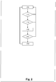
- FIG. 2 shows a schematic representation of the sequence of the embodiment of the method according to the invention.
- step 100 The embodiment of the method according to the invention starts in step 100. Subsequently, step 110 is performed.
- step 110 a check is made by means of a localization method, such as a GPS signal, as to whether the vehicle (10) is approaching a passable stop (24), that is, whether the vehicle (10) is in the vicinity of a passable stop (24). In an advantageous embodiment, it is additionally checked whether the vehicle (10) at a predetermined stop position, which is associated with the passable stop (24) will hold. For this purpose, a stop request of a passenger of the vehicle (10) or a schedule information is evaluated. If the vehicle (10) is located at a passable stop (24), step 120 is performed following step 110. If the vehicle (10) is not at a passable stop, step 100 is performed again following step 110.
- a localization method such as a GPS signal
- step 120 it is checked by means of the first collision warning (14) whether a follower vehicle (30) is located in the monitoring area (26).
- the first collision warning device (14) is located on a rear end wall of the vehicle (10) viewed in the direction of travel of the vehicle (10).
- the monitoring area (26) is located behind the vehicle (10) starting from the direction of travel of the vehicle (10). If a follower vehicle (30) is located in the monitoring area (26), step 130 is performed following step 120. If there is no follower vehicle in the monitoring area (26), step 100 is performed again following step 120.
- step 130 the delay of the follower vehicle (30) is determined.
- a relative speed between the vehicle (10) and the following vehicle (30) is determined by means of the collision warning.
- the intrinsic speed of the vehicle (10) is determined.
- the deceleration of the following vehicle (30) is determined from the relative speed between the vehicle (10) and the following vehicle (30) and the vehicle's own speed (10).
- the intrinsic speed of the vehicle (10) and the relative speed between the vehicle (10) and the following vehicle (30) may each be a function of time.
- step 140 is performed.
- step 140 it is checked whether the amount of the delay determined in step 130 is less than a predefinable threshold value.
- the predefinable threshold value can in turn be a function of a distance between vehicle (10) and follower vehicle (30). If the amount of deceleration of the follower vehicle (30) is less than the predefinable threshold value, step 150 is performed following step 140. Is the amount of the delay of the Following vehicle (30) greater than the predetermined threshold value, step 100 is performed again following step 140.
- the reaction measure may, for example, be a blockage of the doors (18).
- the blocking of the doors (18) can be carried out in particular when the doors (18) are still closed, for example because the vehicle (10) is not yet at a standstill. Thus it can be prevented that in the vehicle (10) passengers located on the in the passable stop (24) located portion of the road (22) go.
- the reaction measure may also include issuing a warning to a driver of the vehicle (10) by means of the output medium (17), which may be in particular a loudspeaker, so that the latter, in accordance with the warnings issued, the doors (18) of the Can drive vehicle (10).
- the reaction measure can also include, by means of the signaling unit (16), which is in particular a warning light, such. B. a yellow beacon, can act to emit an optical warning signal, which is perceived by a driver of the follower vehicle (30).
- the sending out of a warning by means of the signaling unit (16) or the blocking of the doors (18) furthermore has the advantage that passengers waiting inside the passable stop (24) at the edge of the road (22) are able to leave the following vehicle (30 ) can detect outgoing danger and accordingly have the opportunity to enter the section of the road (22) within the passable stop (24) yet.
- the presented embodiment of the method according to the invention therefore offers the possibility of increasing the safety at a stop of the vehicle (10) at a passable stop (24).
Landscapes
- Engineering & Computer Science (AREA)
- Mechanical Engineering (AREA)
- Physics & Mathematics (AREA)
- General Physics & Mathematics (AREA)
- Transportation (AREA)
- Human Computer Interaction (AREA)
- Traffic Control Systems (AREA)
- Emergency Alarm Devices (AREA)
Abstract
Description
- Es gibt immer noch Straßenbahnhaltestellen an mehrspurigen Straßen, bei denen die Bahn in der Mitte der Straße hält und die Fahrgäste eine Autofahrspur überqueren müssen, bevor sie den Bürgersteig erreichen. Hält eine Straßenbahn an einer solchen Haltestelle, setzt die Straßenbahn einen Blinker, der anzeigt, dass Autos nicht auf der rechten Seite an der stehenden Bahn vorbeifahren dürfen, d. h. Autos müssen hinter der Bahn warten, bis der Ein- bzw. Ausstiegsvorgang abgeschlossen ist. Hierbei besteht das Risiko, dass Autofahrer den Blinker übersehen oder die Bedeutung des Blinkers nicht einordnen können. Fahren die Autofahrer an der Bahn vorbei, während gleichzeitig Passagiere aussteigen, kann es zu Unfällen mit schweren Personenschäden kommen.
- Einige Haltestellen dieser Art sind daher mit Ampelanlagen ausgestattet, die eine rechts von der Straßenbahn befindliche Fahrspur mittels eines Rotlichtsignales für nachfolgende Autos sperren. Ist keine Ampelanlage vorhanden, kann ein Straßenbahnführer mittels eines Blicks in den Rückspiegel versuchen abzuschätzen, ob sich hinter der Straßenbahn befindliche Fahrzeuge so verhalten, dass von einer gefahrlosen Öffnung der Tür auszugehen ist. Die aus dem Stand der Technik bekannten Verfahren haben den Nachteil, dass entweder erhebliche Kosten für Infrastruktur aufzuwenden sind oder die Zuverlässigkeit des angewendeten Verfahrens von der persönlichen Erfahrung des Straßenbahnfahrers abhängt.
- Das erfindungsgemäße Verfahren zum Überwachen eines hinter einem Fahrzeug befindlichen Überwachungsbereichs hat den Vorteil, dass eine Verzögerung eines im Überwachungsbereich befindlichen Folgefahrzeugs ermittelt wird und eine Reaktionsmaßnahme eingeleitet wird, wenn ein Betrag der Verzögerung einen vorgebbaren Schwellwert unterschreitet. Die Ermittlung der Verzögerung des Folgefahrzeugs hat den Vorteil, dass es sich bei der Verzögerung des Folgefahrzeugs um einen objektiv messbaren Parameter handelt, der einen Aufschluss darauf zulässt, ob ein Fahrer des Folgefahrzeugs einen Anhaltevorgang des Fahrzeugs erkennt und entsprechend reagiert.
- Bei dem Fahrzeug kann es sich insbesondere um ein Schienenfahrzeug, insbesondere eine Straßenbahn, handeln. Bei dem Folgefahrzeug kann es sich insbesondere um ein Auto handeln.
- Vorteilhaft ist, dass die Verzögerung des Folgefahrzeugs nur dann bestimmt wird, wenn eine Lokalisierung des Fahrzeugs ergibt, dass sich das Fahrzeug in einem Bereich einer durchfahrbaren Haltestelle befindet. Eine durchfahrbare Haltestelle ist dabei eine Haltestelle, bei der sich neben einer vorgesehenen Halteposition des Fahrzeugs mindestens eine Fahrspur befindet, die während des Haltens des Fahrzeugs durch das Folgefahrzeug befahrbar ist. In Ländern mit Rechtsverkehr handelt es sich bei der neben der vorgesehenen Halteposition befindlichen Fahrspur also um eine Fahrspur, die rechts von der vorgesehenen Halteposition des Fahrzeugs angeordnet ist. Unter durchfahrbarer Haltestelle soll außerdem verstanden werden, dass sich zwischen einem Fahrweg des Fahrzeugs, das an der durchfahrbaren Haltestelle anhält, und der danebenliegenden Fahrspur keine bauliche Trennung befindet, die geeignet ist, ein Überqueren der Fahrspur durch Fahrgäste des haltenden Fahrzeugs zu verhindern.
- Bei einer durchfahrbaren Haltestelle kann es sich insbesondere um solch eine Haltestelle handeln, bei der ein Wartebereich, in dem sich wartende Personen aufhalten, die in ein an der Halteposition haltendes Fahrzeug einsteigen möchten, derart angeordnet ist, dass der Wartebereich von der Halteposition des Fahrzeugs durch die Fahrspur getrennt ist, so dass Personen, die in das haltende Fahrzeug einsteigen möchten, die Fahrspur überqueren müssen.
- Vorteilhaft ist, dass die Verzögerung des Folgefahrzeugs ausgehend von einer Relativgeschwindigkeit zwischen dem Fahrzeug und dem Folgefahrzeug ermittelt wird.
- Vorteilhaft ist, dass die Relativgeschwindigkeit unter Verwendung einer Eigengeschwindigkeit des Fahrzeugs ermittelt wird.
- Vorteilhaft ist, dass es sich bei dem vorgebbaren Schwellwert um eine Funktion eines Abstands zwischen dem Fahrzeug und dem Folgefahrzeug handelt. Somit kann zuverlässiger abgeschätzt werden, ob das Folgefahrzeug zum Stehen kommen wird, bevor es das Fahrzeug passiert.
- Vorteilhaft ist, dass die Reaktionsmaßnahme eine Blockierung einer geschlossenen Tür des Fahrzeugs, eine Ausgabe einer Warnung an einen Fahrer des Fahrzeugs und/oder eine Ausgabe einer Warnung an einen Fahrer des Folgefahrzeugs umfasst. Durch eine Blockierung der geschlossenen Tür des Fahrzeugs kann vorteilhafter Weise verhindert werden, dass Fahrgäste des Fahrzeugs aus dem Fahrzeug aussteigen und sich somit in Gefahr begeben.
- Vorteilhaft ist, dass es sich bei dem Fahrzeug um ein Schienenfahrzeug und bei dem Folgefahrzeug um ein Straßenfahrzeug handelt. Das Schienenfahrzeug befährt dabei vorteilhafter Weise einen Gleisabschnitt, das Straßenfahrzeug befährt vorteilhafter Weise eine Fahrspur einer Straße.
- Vorteilhafter Weise wird das erfindungsgemäße Verfahren unter Verwendung eines an dem Fahrzeug befindlichen Kollisionswarners durchgeführt. Vorteilhafter Weise handelt es sich bei dem Fahrzeug um ein Zwei-Richtungs-Fahrzeug, wobei jede Stirnseite des Fahrzeugs mit einem Kollisionswarner ausgestattet ist. Ein in Fahrtrichtung des Fahrzeugs gesehen an der hinteren Stirnwand angebrachter Kollisionswarner kann vorteilhafter Weise verwendet werden, um einen in Fahrtrichtung gesehen hinter dem Fahrzeug befindlichen Überwachungsbereich zu überwachen.
- Vorteilhafter Weise handelt es sich bei dem Kollisionswarner um einen Kollisionswarner, der einen Radarsensor, eine Kamera oder einen LiDAR-Sensor umfasst.
- Vorteilhafter Weise wird das erfindungsgemäße Verfahren dann durchgeführt, wenn sich das Fahrzeug, beispielsweise eine Straßenbahn, einer durchfahrbaren Haltestelle nähert und aufgrund einer Fahrplaninformation oder eines Haltewunsches eines Fahrgastes ermittelt wird, dass das Fahrzeug, beispielsweise eine Straßenbahn, an einer Halteposition der durchfahrbaren Haltestelle anhalten wird. Das erfindungsgemäße Verfahren bietet vorteilhafter Weise eine Möglichkeit, abzuschätzen, ob das Folgefahrzeug den Halt des Fahrzeugs, beispielsweise der Straßenbahn erkennt und entsprechend reagiert.
- Vorteilhaft ist eine Vorrichtung, die eingerichtet ist, jeden Schritt des erfindungsgemäßen Verfahrens auszuführen.
- Vorteilhaft ist ein Computerprogrammprodukt, das eingerichtet ist oder durch Kompilieren dazu eingerichtet wird, jeden Schritt des erfindungsgemäßen Verfahrens durchzuführen, insbesondere wenn es auf einer Steuereinrichtung abläuft.
- Vorteilhaft ist ein Speichermedium, auf dem das erfindungsgemäße Computerprogramm gespeichert ist.
- Vorteilhaft ist eine Steuereinheit, die das erfindungsgemäße Speichermedium umfasst.
- Im Folgenden wird ein Ausführungsbeispiel des erfindungsgemäßen Verfahrens näher beschrieben. Dabei zeigen:
- Figur 1
- eine schematische Darstellung eines zur Durchführung des Ausführungsbeispiels des erfindungsgemäßen Verfahrens eingerichteten Fahrzeugs;
- Figur 2
- eine schematische Darstellung eines Ablaufs des Ausführungsbeispiels des erfindungsgemäßen Verfahrens.
-
Figur 1 zeigt eine schematische Darstellung eines Fahrzeugs (10), bei dem es sich insbesondere um ein Schienenfahrzeug, insbesondere eine Straßenbahn, handeln kann. Das Fahrzeug (10) ist zur Durchführung eines Ausführungsbeispiels des erfindungsgemäßen Verfahrens eingerichtet. - Das Fahrzeug (10) umfasst eine Steuereinheit (12), die wiederum einen Speicher (13) umfasst. Das Fahrzeug (10) umfasst einen ersten Kollisionswarner (14), der sich an einer ersten Stirnseite des Fahrzeugs (10) befindet, sowie einen zweiten Kollisionswarner (15), der sich an einer zweiten Stirnseite des Fahrzeugs (10) befindet. Das Fahrzeug (10) umfasst außerdem mehrere Türen (18), durch die Fahrgäste das Fahrzeug (10) betreten oder verlassen können, eine nach außen gerichtete Signalisierungseinheit (16), bei der es sich insbesondere um ein Warnlicht handeln kann, sowie ein nach innen wirkendes Ausgabemedium (17), bei dem es sich insbesondere um einen Lautsprecher handeln kann.
- Bei dem ersten Kollisionswarner (14) und dem zweiten Kollisionswarner (15) kann es sich insbesondere um vom Markt her bekannte Kollisionswarner handeln, die beispielsweise einen Radarsensor, eine Kamera und/oder einen LiDAR-Sensor umfassen und eingerichtet sind, einen Überwachungsbereich (26) auf die Anwesenheit von Objekten wie beispielsweise einem Folgefahrzeug (30), bei dem es sich insbesondere um ein Straßenfahrzeug handelt, zu überwachen. Der erste und der zweite Kollisionswarner (14, 15) sind insbesondere dazu eingerichtet, eine Geschwindigkeit des Folgefahrzeugs (30) zu erfassen.
Der Überwachungsbereich (26) kann eine Teilmenge eines dem ersten bzw. zweiten Kollisionswarner (14, 15) zugeordneten Erfassungsbereiches darstellen, d. h. der erste bzw. der zweite Kollisionswarner (14, 15) kann derart eingerichtet sein, dass er ein Folgefahrzeug (30) nur als solches erkennt, wenn sich das Folgefahrzeug (30) auch im Überwachungsbereich (26) befindet, wobei der erste bzw. zweite Kollisionwarner (14, 15) bezüglich seines Sichtwinkels und seiner Reichweite in der Lage wäre, ein Folgefahrzeug (30) auch dann zu erkennen, wenn sich dieses außerhalb des Überwachungsbereichs (26) befindet. Mit anderen Worten wird der Überwachungsbereich (26) nicht durch die Reichweite oder den Sehwinkel des ersten bzw. zweiten Kollisionwarners (14, 15) definiert, sondern kann anhand anderer Kriterien wie beispielsweise der Lage einer Straße (22) und der Lage einer Haltestelle (24) definiert werden. - Im in
Figur 1 dargestellten Beispiel befindet sich das Fahrzeug (10) auf einem Gleis (20), neben dem sich wiederum die Straße (22) befindet. Ein Teil der Straße (22) bildet einen Teil einer Haltestelle (24), wobei es sich bei der Haltestelle (24) um eine sogenannte durchfahrbare Haltestelle handelt. Fahrgäste, die das Fahrzeug (10) besteigen wollen, sobald das Fahrzeug (10) an einer vorgebbaren Halteposition hält, warten innerhalb der Haltestelle (24) am Rand der Straße (22), bis das Fahrzeug (10) zum Stehen kommt. Daraufhin überqueren die Fahrgäste die Straße (22), um das Fahrzeug (10) durch die geöffneten Türen (18) zu betreten. - Der Überwachungsbereich (26) ist insbesondere derart definiert, dass er entgegen der Fahrtrichtung des Fahrzeugs (10) gesehen unmittelbar hinter der Haltestelle (24) liegt und die gesamte Breite der Straße (22) überdeckt. Die Ausdehnung des Überwachungsbereichs (26) in Richtung der Straße (22) kann beispielsweise 20 oder 50 Meter betragen.
- Das Fahrzeug (10) ist außerdem mittels einer entsprechenden Sensorik eingerichtet, eine Eigengeschwindigkeit, d. h. seine eigene Geschwindigkeit zu erfassen.
-
Figur 2 zeigt eine schematische Darstellung des Ablaufs des Ausführungsbeispiels des erfindungsgemäßen Verfahrens. - Das Ausführungsbeispiel des erfindungsgemäßen Verfahrens startet in Schritt 100. Anschließend wird Schritt 110 durchgeführt.
- In Schritt 110 wird mittels einer Lokalisierungsmethode wie beispielsweise einem GPS-Signal überprüft, ob sich das Fahrzeug (10) einer durchfahrbaren Haltestelle (24) nähert, also, ob sich das Fahrzeug (10) im Bereich einer durchfahrbaren Haltestelle (24) befindet. In vorteilhafter Ausgestaltung wird zusätzlich überprüft, ob das Fahrzeug (10) an einer vorgegebenen Halteposition, die der durchfahrbaren Haltestelle (24) zugeordnet ist, halten wird. Hierfür kein ein Haltewunsch eines Fahrgastes des Fahrzeugs (10) oder eine Fahrplaninformation ausgewertet werden. Befindet sich das Fahrzeug (10) an einer durchfahrbaren Haltestelle (24), wird im Anschluss an Schritt 110 Schritt 120 durchgeführt. Befindet sich das Fahrzeug (10) nicht an einer durchfahrbaren Haltestelle, wird im Anschluss an Schritt 110 erneut Schritt 100 durchgeführt.
- In Schritt 120 wird mittels des ersten Kollisionwarners (14) überprüft, ob sich ein Folgefahrzeug (30) im Überwachungsbereich (26) befindet. Der erste Kollisionswarner (14) befindet sich dabei an einer in Fahrtrichtung des Fahrzeugs (10) gesehen hinteren Stirnwand des Fahrzeugs (10). Der Überwachungsbereich (26) befindet sich ausgehend von der Fahrtrichtung des Fahrzeugs (10) hinter dem Fahrzeug (10). Befindet sich ein Folgefahrzeug (30) im Überwachungsbereich (26), wird im Anschluss an Schritt 120 Schritt 130 durchgeführt. Befindet sich kein Folgefahrzeug im Überwachungsbereich (26), wird im Anschluss an Schritt 120 erneut Schritt 100 durchgeführt.
- In Schritt 130 wird die Verzögerung des Folgefahrzeugs (30) bestimmt. Hierfür wird mittels des Kollisionswarners eine Relativgeschwindigkeit zwischen Fahrzeug (10) und Folgefahrzeug (30) bestimmt. Darüber hinaus wird die Eigengeschwindigkeit des Fahrzeugs (10) bestimmt. Aus der Relativgeschwindigkeit zwischen Fahrzeug (10) und Folgefahrzeug (30) sowie der Eigengeschwindigkeit des Fahrzeugs (10) wird die Verzögerung des Folgefahrzeugs (30) ermittelt. Bei der Eigengeschwindigkeit des Fahrzeugs (10) sowie der Relativgeschwindigkeit zwischen Fahrzeug (10) und Folgefahrzeug (30) kann es sich jeweils um eine Funktion der Zeit handeln. Im Anschluss an Schritt 130 wird Schritt 140 durchgeführt.
- In Schritt 140 wird überprüft, ob der Betrag der in Schritt 130 ermittelten Verzögerung kleiner als ein vorgebbarer Schwellwert ist. Der vorgebbare Schwellwert kann hierbei wiederum eine Funktion eines Abstandes zwischen Fahrzeug (10) und Folgefahrzeug (30) sein. Ist der Betrag der Verzögerung des Folgefahrzeugs (30) kleiner als der vorgebbare Schwellwert, wird im Anschluss an Schritt 140 Schritt 150 durchgeführt. Ist der Betrag der Verzögerung des Folgefahrzeugs (30) größer als der vorgebbare Schwellwert, wird im Anschluss an Schritt 140 erneut Schritt 100 durchgeführt.
- In Schritt 150 wird eine Reaktionsmaßnahme eingeleitet. Bei der Reaktionsmaßnahme kann es sich beispielsweise um ein Blockieren der Türen (18) handeln. Das Blockieren der Türen (18) kann insbesondere dann vorgenommen werden, wenn die Türen (18) noch verschlossen sind, beispielsweise da sich das Fahrzeug (10) noch nicht im Stillstand befindet. Somit kann verhindert werden, dass sich im Fahrzeug (10) befindliche Fahrgäste auf den in der durchfahrbaren Haltestelle (24) befindlichen Abschnitt der Straße (22) begeben. Die Reaktionsmaßnahme kann außerdem umfassen, mittels des Ausgabemediums (17), bei dem es sich insbesondere um einen Lautsprecher handeln kann, eine Warnung an einen Fahrer des Fahrzeugs (10) auszugeben, so dass dieser unter Beachtung der ausgegebenen Warnungen die Türen (18) des Fahrzeugs (10) ansteuern kann. Die Reaktionsmaßnahme kann außerdem umfassen, mittels der Signalisierungseinheit (16), bei der es sich insbesondere um ein Warnlicht, wie z. B. eine gelbe Rundumleuchte, handeln kann, ein optisches Warnsignal auszusenden, das von einem Fahrer des Folgefahrzeugs (30) wahrgenommen wird.
- Das Aussenden einer Warnung mittels der Signalisierungseinheit (16) oder das Blockieren der Türen (18) hat darüber hinaus den Vorteil, dass Fahrgäste, die innerhalb der durchfahrbaren Haltestelle (24) am Rand der Straße (22) warten, die von dem Folgefahrzeug (30) ausgehende Gefahr erkennen können und entsprechend die Möglichkeit haben, den Abschnitt der Straße (22) innerhalb der durchfahrbaren Haltestelle (24) noch nicht zu betreten.
- Das vorgestellte Ausführungsbeispiel des erfindungsgemäßen Verfahrens bietet daher die Möglichkeit, die Sicherheit bei einem Halt des Fahrzeugs (10) an einer durchfahrbaren Haltestelle (24) zu erhöhen.
Claims (11)
- Verfahren zum Überwachen eines hinter einem Fahrzeug (10) befindlichen Überwachungsbereichs (26), dadurch gekennzeichnet, dass eine Verzögerung eines im Überwachungsbereich (26) befindlichen Folgefahrzeugs (30) ermittelt wird und eine Reaktionsmaßnahme eingeleitet wird, wenn ein Betrag der Verzögerung einen vorgebbaren Schwellwert unterschreitet.
- Verfahren nach Anspruch 1, dadurch gekennzeichnet, dass die Verzögerung des Folgefahrzeugs (30) nur dann bestimmt wird, wenn eine Lokalisierung des Fahrzeugs (10) ergibt, dass sich das Fahrzeug (10) in einem Bereich einer durchfahrbaren Haltestelle (24) befindet.
- Verfahren nach Anspruch 1 oder 2, dadurch gekennzeichnet, dass die Verzögerung des Folgefahrzeugs (30) ausgehend von einer Relativgeschwindigkeit zwischen dem Fahrzeug (10) und dem Folgefahrzeug (30) ermittelt wird.
- Verfahren nach Anspruch 3, dadurch gekennzeichnet, dass die Relativgeschwindigkeit unter Verwendung einer Eigengeschwindigkeit des Fahrzeugs (10) ermittelt wird.
- Verfahren nach einem der vorangegangenen Ansprüche, dadurch gekennzeichnet, dass es sich bei dem vorgebbaren Schwellwert um eine Funktion eines Abstands zwischen dem Fahrzeug (10) und dem Folgefahrzeug (30) handelt.
- Verfahren nach einem der vorangegangenen Ansprüche, dadurch gekennzeichnet, dass die Reaktionsmaßnahme eine Blockierung einer geschlossenen Tür (18) des Fahrzeugs (10), eine Ausgabe einer Warnung an einen Fahrer des Fahrzeugs (10) und/oder eine Ausgabe einer Warnung an einen Fahrer des Folgefahrzeugs (30) umfasst.
- Verfahren nach einem der vorangegangenen Ansprüche, dadurch gekennzeichnet, dass es sich bei dem Fahrzeug (10) um ein Schienenfahrzeug und bei dem Folgefahrzeug (30) um ein Straßenfahrzeug handelt.
- Vorrichtung, eingerichtet jeden Schritt des Verfahrens nach einem der vorangegangenen Ansprüche auszuführen.
- Computerprogrammprodukt, das eingerichtet ist oder durch Kompilieren dazu eingerichtet wird, jeden Schritt des Verfahrens nach einem der vorangegangenen Ansprüche durchzuführen, wenn es auf einer Steuereinrichtung abläuft.
- Speichermedium, auf dem das Computerprogramm nach Anspruch 9 gespeichert ist.
- Steuereinheit, die das Speichermedium nach Anspruch 10 umfasst.
Applications Claiming Priority (1)
| Application Number | Priority Date | Filing Date | Title |
|---|---|---|---|
| DE102017210605.0A DE102017210605A1 (de) | 2017-06-23 | 2017-06-23 | Verfahren zum Überwachen eines hinter einem Fahrzeug befindlichen Überwachungsbereichs |
Publications (3)
| Publication Number | Publication Date |
|---|---|
| EP3419003A2 true EP3419003A2 (de) | 2018-12-26 |
| EP3419003A3 EP3419003A3 (de) | 2019-01-02 |
| EP3419003B1 EP3419003B1 (de) | 2024-03-20 |
Family
ID=62748725
Family Applications (1)
| Application Number | Title | Priority Date | Filing Date |
|---|---|---|---|
| EP18178204.6A Active EP3419003B1 (de) | 2017-06-23 | 2018-06-18 | Verfahren zum überwachen eines hinter einem fahrzeug befindlichen überwachungsbereichs |
Country Status (2)
| Country | Link |
|---|---|
| EP (1) | EP3419003B1 (de) |
| DE (1) | DE102017210605A1 (de) |
Family Cites Families (8)
| Publication number | Priority date | Publication date | Assignee | Title |
|---|---|---|---|---|
| DE10225921B4 (de) * | 2002-06-11 | 2007-05-31 | Hermann Eser | System zur Geschwindigkeitsmessung |
| DE102005013335B4 (de) * | 2005-03-23 | 2025-06-12 | Bayerische Motoren Werke Aktiengesellschaft | Auffahr-Warnsystem |
| DE102005062274A1 (de) * | 2005-12-24 | 2007-06-28 | Daimlerchrysler Ag | Verfahren zur Erkennung eines drohenden Heckaufpralls |
| GB2436916B (en) * | 2006-03-29 | 2008-09-24 | John Turnbull | Warning System |
| DE102007000449A1 (de) * | 2006-08-17 | 2008-03-27 | Vis-à-pix GmbH | Vorrichtung und Verfahren zur automatischen Zaehlung von Objekten auf beweglichem oder bewegtem Untergrund |
| DE102009031832A1 (de) * | 2009-07-03 | 2011-01-05 | Erwin Mertens | Lichtsignalanlage als Vorampel einer Straßenbahnhaltestelle |
| SE539046C2 (en) * | 2014-09-22 | 2017-03-28 | Scania Cv Ab | Method and system for warning for vulnerable road users in connection to a non-moving vehicle |
| DE202016004062U1 (de) * | 2016-06-24 | 2016-08-23 | Kastriot Merlaku | Lichtmarkierungs-System für Fahrzeuge |
-
2017
- 2017-06-23 DE DE102017210605.0A patent/DE102017210605A1/de active Pending
-
2018
- 2018-06-18 EP EP18178204.6A patent/EP3419003B1/de active Active
Non-Patent Citations (1)
| Title |
|---|
| None |
Also Published As
| Publication number | Publication date |
|---|---|
| EP3419003A3 (de) | 2019-01-02 |
| EP3419003B1 (de) | 2024-03-20 |
| DE102017210605A1 (de) | 2018-12-27 |
Similar Documents
| Publication | Publication Date | Title |
|---|---|---|
| DE102013214233B4 (de) | Intelligentes Vorwärtskollisionswarnsystem | |
| DE102011086241B4 (de) | Verfahren zum sicheren Abstellen eines Fahrzeuges | |
| DE60025130T2 (de) | System zum Verhindern von Zusammenstössen zwischen Fahrzeugen und Fussgängern | |
| DE102015209671B4 (de) | Fahrerassistenzsystem zur Überquerung eines Bahnübergangs | |
| DE102014009059B4 (de) | Seiten-Rückwärts-Alarmsystem für Fahrzeuge und Alarmsteuerverfahren für dieses | |
| DE102014201159A1 (de) | Verfahren und Vorrichtung zum Klassifizieren eines Verhaltens eines Fußgängers beim Überqueren einer Fahrbahn eines Fahrzeugs sowie Personenschutzsystem eines Fahrzeugs | |
| DE102016102143A1 (de) | Fahrzeugfahrunterstützungssystem | |
| DE102014208673A1 (de) | Verfahren und Verkehrsüberwachungseinrichtung zum Feststellen einer Falschfahrt eines Kraftfahrzeugs | |
| DE102014223744A1 (de) | Assistenzsystem zur Detektion von in der Umgebung eines Fahrzeuges auftretenden Fahrhindernissen | |
| DE102013210941A1 (de) | Verfahren und Vorrichtung zum Betreiben eines Fahrzeugs | |
| EP3373268A1 (de) | Verfahren zum betreiben eines fahrerassistenzsystems für ein fahrzeug auf einer strasse und fahrerassistenzsystem | |
| DE10244205A1 (de) | Verfahren und Einrichtung zur Verhinderung der Kollision von Fahrzeugen | |
| DE102013004271A1 (de) | Verfahren und Vorrichtung zur Unterstützung eines Fahrers beim Führen eines Fahrzeugs | |
| DE102006047634A1 (de) | Verfahren zum Erfassen eines Umfelds eines Fahrzeugs | |
| WO2020001698A1 (de) | Fahrerassistenzsystem mit einer nothaltefunktion für ein fahrzeug, fahrzeug mit demselben und verfahren zum nothalten eines fahrzeugs | |
| DE102013001017A1 (de) | Verfahren zum Betreiben eines Fahrzeugs und Fahrzeug | |
| DE102012212175A1 (de) | Verfahren und Vorrichtung zum Betreiben eines Fahrzeugs | |
| EP2425414B1 (de) | Verfahren und vorrichtung zur verkehrssteuerung an einem bahnübergang | |
| DE102014220685A1 (de) | Bereitstellen einer Mindestabstandsangabe in einem Kraftfahrzeug | |
| DE102014215273A1 (de) | Steuerung eines Kraftfahrzeugs | |
| WO2019007718A1 (de) | System und verfahren zum automatisierten manövrieren eines ego-fahrzeugs | |
| DE102014217877A1 (de) | Vorrichtung und Verfahren zum Erkennen von Verkehrszeichen | |
| EP4209406A1 (de) | Verfahren zur steuerung eines automatisierten parksystems und automatisiertes parksystem | |
| DE102019205017B3 (de) | Intentionsbestimmung eines Personenverkehrsmittels | |
| DE102014207054B4 (de) | Verfahren zum Betreiben eines Fahrerinformationssystem für Engstellen im Straßenverkehr und Fahrerinformationssystem |
Legal Events
| Date | Code | Title | Description |
|---|---|---|---|
| PUAI | Public reference made under article 153(3) epc to a published international application that has entered the european phase |
Free format text: ORIGINAL CODE: 0009012 |
|
| STAA | Information on the status of an ep patent application or granted ep patent |
Free format text: STATUS: THE APPLICATION HAS BEEN PUBLISHED |
|
| PUAL | Search report despatched |
Free format text: ORIGINAL CODE: 0009013 |
|
| AK | Designated contracting states |
Kind code of ref document: A2 Designated state(s): AL AT BE BG CH CY CZ DE DK EE ES FI FR GB GR HR HU IE IS IT LI LT LU LV MC MK MT NL NO PL PT RO RS SE SI SK SM TR |
|
| AX | Request for extension of the european patent |
Extension state: BA ME |
|
| AK | Designated contracting states |
Kind code of ref document: A3 Designated state(s): AL AT BE BG CH CY CZ DE DK EE ES FI FR GB GR HR HU IE IS IT LI LT LU LV MC MK MT NL NO PL PT RO RS SE SI SK SM TR |
|
| AX | Request for extension of the european patent |
Extension state: BA ME |
|
| RIC1 | Information provided on ipc code assigned before grant |
Ipc: G08G 1/16 20060101AFI20181128BHEP Ipc: B60Q 1/52 20060101ALI20181128BHEP |
|
| STAA | Information on the status of an ep patent application or granted ep patent |
Free format text: STATUS: REQUEST FOR EXAMINATION WAS MADE |
|
| 17P | Request for examination filed |
Effective date: 20190702 |
|
| RBV | Designated contracting states (corrected) |
Designated state(s): AL AT BE BG CH CY CZ DE DK EE ES FI FR GB GR HR HU IE IS IT LI LT LU LV MC MK MT NL NO PL PT RO RS SE SI SK SM TR |
|
| RAP1 | Party data changed (applicant data changed or rights of an application transferred) |
Owner name: ROBERT BOSCH GMBH |
|
| STAA | Information on the status of an ep patent application or granted ep patent |
Free format text: STATUS: EXAMINATION IS IN PROGRESS |
|
| 17Q | First examination report despatched |
Effective date: 20210531 |
|
| RIC1 | Information provided on ipc code assigned before grant |
Ipc: B61L 25/02 20060101ALN20230927BHEP Ipc: B61L 23/04 20060101ALI20230927BHEP Ipc: B61L 15/00 20060101ALI20230927BHEP Ipc: B61D 19/02 20060101ALI20230927BHEP Ipc: B61D 13/00 20060101ALI20230927BHEP Ipc: B60Q 9/00 20060101ALI20230927BHEP Ipc: B60Q 1/50 20060101ALI20230927BHEP Ipc: G08G 1/16 20060101AFI20230927BHEP |
|
| RIC1 | Information provided on ipc code assigned before grant |
Ipc: B61L 25/02 20060101ALN20231003BHEP Ipc: B61L 23/04 20060101ALI20231003BHEP Ipc: B61L 15/00 20060101ALI20231003BHEP Ipc: B61D 19/02 20060101ALI20231003BHEP Ipc: B61D 13/00 20060101ALI20231003BHEP Ipc: B60Q 9/00 20060101ALI20231003BHEP Ipc: B60Q 1/50 20060101ALI20231003BHEP Ipc: G08G 1/16 20060101AFI20231003BHEP |
|
| GRAP | Despatch of communication of intention to grant a patent |
Free format text: ORIGINAL CODE: EPIDOSNIGR1 |
|
| STAA | Information on the status of an ep patent application or granted ep patent |
Free format text: STATUS: GRANT OF PATENT IS INTENDED |
|
| RIC1 | Information provided on ipc code assigned before grant |
Ipc: B61L 25/02 20060101ALN20231018BHEP Ipc: B61L 23/04 20060101ALI20231018BHEP Ipc: B61L 15/00 20060101ALI20231018BHEP Ipc: B61D 19/02 20060101ALI20231018BHEP Ipc: B61D 13/00 20060101ALI20231018BHEP Ipc: B60Q 9/00 20060101ALI20231018BHEP Ipc: B60Q 1/50 20060101ALI20231018BHEP Ipc: G08G 1/16 20060101AFI20231018BHEP |
|
| INTG | Intention to grant announced |
Effective date: 20231121 |
|
| RIC1 | Information provided on ipc code assigned before grant |
Ipc: B61L 25/02 20060101ALN20231110BHEP Ipc: B61L 23/04 20060101ALI20231110BHEP Ipc: B61L 15/00 20060101ALI20231110BHEP Ipc: B61D 19/02 20060101ALI20231110BHEP Ipc: B61D 13/00 20060101ALI20231110BHEP Ipc: B60Q 9/00 20060101ALI20231110BHEP Ipc: B60Q 1/50 20060101ALI20231110BHEP Ipc: G08G 1/16 20060101AFI20231110BHEP |
|
| GRAS | Grant fee paid |
Free format text: ORIGINAL CODE: EPIDOSNIGR3 |
|
| GRAA | (expected) grant |
Free format text: ORIGINAL CODE: 0009210 |
|
| STAA | Information on the status of an ep patent application or granted ep patent |
Free format text: STATUS: THE PATENT HAS BEEN GRANTED |
|
| AK | Designated contracting states |
Kind code of ref document: B1 Designated state(s): AL AT BE BG CH CY CZ DE DK EE ES FI FR GB GR HR HU IE IS IT LI LT LU LV MC MK MT NL NO PL PT RO RS SE SI SK SM TR |
|
| REG | Reference to a national code |
Ref country code: GB Ref legal event code: FG4D Free format text: NOT ENGLISH |
|
| REG | Reference to a national code |
Ref country code: CH Ref legal event code: EP |
|
| REG | Reference to a national code |
Ref country code: DE Ref legal event code: R096 Ref document number: 502018014274 Country of ref document: DE |
|
| REG | Reference to a national code |
Ref country code: IE Ref legal event code: FG4D Free format text: LANGUAGE OF EP DOCUMENT: GERMAN |
|
| PG25 | Lapsed in a contracting state [announced via postgrant information from national office to epo] |
Ref country code: LT Free format text: LAPSE BECAUSE OF FAILURE TO SUBMIT A TRANSLATION OF THE DESCRIPTION OR TO PAY THE FEE WITHIN THE PRESCRIBED TIME-LIMIT Effective date: 20240320 |
|
| REG | Reference to a national code |
Ref country code: LT Ref legal event code: MG9D |
|
| PG25 | Lapsed in a contracting state [announced via postgrant information from national office to epo] |
Ref country code: GR Free format text: LAPSE BECAUSE OF FAILURE TO SUBMIT A TRANSLATION OF THE DESCRIPTION OR TO PAY THE FEE WITHIN THE PRESCRIBED TIME-LIMIT Effective date: 20240621 |
|
| PG25 | Lapsed in a contracting state [announced via postgrant information from national office to epo] |
Ref country code: RS Free format text: LAPSE BECAUSE OF FAILURE TO SUBMIT A TRANSLATION OF THE DESCRIPTION OR TO PAY THE FEE WITHIN THE PRESCRIBED TIME-LIMIT Effective date: 20240620 Ref country code: HR Free format text: LAPSE BECAUSE OF FAILURE TO SUBMIT A TRANSLATION OF THE DESCRIPTION OR TO PAY THE FEE WITHIN THE PRESCRIBED TIME-LIMIT Effective date: 20240320 |
|
| REG | Reference to a national code |
Ref country code: NL Ref legal event code: MP Effective date: 20240320 |
|
| PG25 | Lapsed in a contracting state [announced via postgrant information from national office to epo] |
Ref country code: RS Free format text: LAPSE BECAUSE OF FAILURE TO SUBMIT A TRANSLATION OF THE DESCRIPTION OR TO PAY THE FEE WITHIN THE PRESCRIBED TIME-LIMIT Effective date: 20240620 Ref country code: NO Free format text: LAPSE BECAUSE OF FAILURE TO SUBMIT A TRANSLATION OF THE DESCRIPTION OR TO PAY THE FEE WITHIN THE PRESCRIBED TIME-LIMIT Effective date: 20240620 Ref country code: LT Free format text: LAPSE BECAUSE OF FAILURE TO SUBMIT A TRANSLATION OF THE DESCRIPTION OR TO PAY THE FEE WITHIN THE PRESCRIBED TIME-LIMIT Effective date: 20240320 Ref country code: HR Free format text: LAPSE BECAUSE OF FAILURE TO SUBMIT A TRANSLATION OF THE DESCRIPTION OR TO PAY THE FEE WITHIN THE PRESCRIBED TIME-LIMIT Effective date: 20240320 Ref country code: GR Free format text: LAPSE BECAUSE OF FAILURE TO SUBMIT A TRANSLATION OF THE DESCRIPTION OR TO PAY THE FEE WITHIN THE PRESCRIBED TIME-LIMIT Effective date: 20240621 Ref country code: FI Free format text: LAPSE BECAUSE OF FAILURE TO SUBMIT A TRANSLATION OF THE DESCRIPTION OR TO PAY THE FEE WITHIN THE PRESCRIBED TIME-LIMIT Effective date: 20240320 Ref country code: BG Free format text: LAPSE BECAUSE OF FAILURE TO SUBMIT A TRANSLATION OF THE DESCRIPTION OR TO PAY THE FEE WITHIN THE PRESCRIBED TIME-LIMIT Effective date: 20240320 |
|
| PG25 | Lapsed in a contracting state [announced via postgrant information from national office to epo] |
Ref country code: SE Free format text: LAPSE BECAUSE OF FAILURE TO SUBMIT A TRANSLATION OF THE DESCRIPTION OR TO PAY THE FEE WITHIN THE PRESCRIBED TIME-LIMIT Effective date: 20240320 Ref country code: LV Free format text: LAPSE BECAUSE OF FAILURE TO SUBMIT A TRANSLATION OF THE DESCRIPTION OR TO PAY THE FEE WITHIN THE PRESCRIBED TIME-LIMIT Effective date: 20240320 |
|
| PG25 | Lapsed in a contracting state [announced via postgrant information from national office to epo] |
Ref country code: NL Free format text: LAPSE BECAUSE OF FAILURE TO SUBMIT A TRANSLATION OF THE DESCRIPTION OR TO PAY THE FEE WITHIN THE PRESCRIBED TIME-LIMIT Effective date: 20240320 |
|
| PG25 | Lapsed in a contracting state [announced via postgrant information from national office to epo] |
Ref country code: NL Free format text: LAPSE BECAUSE OF FAILURE TO SUBMIT A TRANSLATION OF THE DESCRIPTION OR TO PAY THE FEE WITHIN THE PRESCRIBED TIME-LIMIT Effective date: 20240320 |
|
| PG25 | Lapsed in a contracting state [announced via postgrant information from national office to epo] |
Ref country code: IS Free format text: LAPSE BECAUSE OF FAILURE TO SUBMIT A TRANSLATION OF THE DESCRIPTION OR TO PAY THE FEE WITHIN THE PRESCRIBED TIME-LIMIT Effective date: 20240720 |
|
| PG25 | Lapsed in a contracting state [announced via postgrant information from national office to epo] |
Ref country code: PT Free format text: LAPSE BECAUSE OF FAILURE TO SUBMIT A TRANSLATION OF THE DESCRIPTION OR TO PAY THE FEE WITHIN THE PRESCRIBED TIME-LIMIT Effective date: 20240722 Ref country code: SM Free format text: LAPSE BECAUSE OF FAILURE TO SUBMIT A TRANSLATION OF THE DESCRIPTION OR TO PAY THE FEE WITHIN THE PRESCRIBED TIME-LIMIT Effective date: 20240320 |
|
| PG25 | Lapsed in a contracting state [announced via postgrant information from national office to epo] |
Ref country code: ES Free format text: LAPSE BECAUSE OF FAILURE TO SUBMIT A TRANSLATION OF THE DESCRIPTION OR TO PAY THE FEE WITHIN THE PRESCRIBED TIME-LIMIT Effective date: 20240320 |
|
| PG25 | Lapsed in a contracting state [announced via postgrant information from national office to epo] |
Ref country code: CZ Free format text: LAPSE BECAUSE OF FAILURE TO SUBMIT A TRANSLATION OF THE DESCRIPTION OR TO PAY THE FEE WITHIN THE PRESCRIBED TIME-LIMIT Effective date: 20240320 Ref country code: EE Free format text: LAPSE BECAUSE OF FAILURE TO SUBMIT A TRANSLATION OF THE DESCRIPTION OR TO PAY THE FEE WITHIN THE PRESCRIBED TIME-LIMIT Effective date: 20240320 |
|
| PG25 | Lapsed in a contracting state [announced via postgrant information from national office to epo] |
Ref country code: PL Free format text: LAPSE BECAUSE OF FAILURE TO SUBMIT A TRANSLATION OF THE DESCRIPTION OR TO PAY THE FEE WITHIN THE PRESCRIBED TIME-LIMIT Effective date: 20240320 |
|
| PG25 | Lapsed in a contracting state [announced via postgrant information from national office to epo] |
Ref country code: SK Free format text: LAPSE BECAUSE OF FAILURE TO SUBMIT A TRANSLATION OF THE DESCRIPTION OR TO PAY THE FEE WITHIN THE PRESCRIBED TIME-LIMIT Effective date: 20240320 |
|
| PG25 | Lapsed in a contracting state [announced via postgrant information from national office to epo] |
Ref country code: SM Free format text: LAPSE BECAUSE OF FAILURE TO SUBMIT A TRANSLATION OF THE DESCRIPTION OR TO PAY THE FEE WITHIN THE PRESCRIBED TIME-LIMIT Effective date: 20240320 Ref country code: SK Free format text: LAPSE BECAUSE OF FAILURE TO SUBMIT A TRANSLATION OF THE DESCRIPTION OR TO PAY THE FEE WITHIN THE PRESCRIBED TIME-LIMIT Effective date: 20240320 Ref country code: RO Free format text: LAPSE BECAUSE OF FAILURE TO SUBMIT A TRANSLATION OF THE DESCRIPTION OR TO PAY THE FEE WITHIN THE PRESCRIBED TIME-LIMIT Effective date: 20240320 Ref country code: PT Free format text: LAPSE BECAUSE OF FAILURE TO SUBMIT A TRANSLATION OF THE DESCRIPTION OR TO PAY THE FEE WITHIN THE PRESCRIBED TIME-LIMIT Effective date: 20240722 Ref country code: PL Free format text: LAPSE BECAUSE OF FAILURE TO SUBMIT A TRANSLATION OF THE DESCRIPTION OR TO PAY THE FEE WITHIN THE PRESCRIBED TIME-LIMIT Effective date: 20240320 Ref country code: IS Free format text: LAPSE BECAUSE OF FAILURE TO SUBMIT A TRANSLATION OF THE DESCRIPTION OR TO PAY THE FEE WITHIN THE PRESCRIBED TIME-LIMIT Effective date: 20240720 Ref country code: ES Free format text: LAPSE BECAUSE OF FAILURE TO SUBMIT A TRANSLATION OF THE DESCRIPTION OR TO PAY THE FEE WITHIN THE PRESCRIBED TIME-LIMIT Effective date: 20240320 Ref country code: EE Free format text: LAPSE BECAUSE OF FAILURE TO SUBMIT A TRANSLATION OF THE DESCRIPTION OR TO PAY THE FEE WITHIN THE PRESCRIBED TIME-LIMIT Effective date: 20240320 Ref country code: CZ Free format text: LAPSE BECAUSE OF FAILURE TO SUBMIT A TRANSLATION OF THE DESCRIPTION OR TO PAY THE FEE WITHIN THE PRESCRIBED TIME-LIMIT Effective date: 20240320 |
|
| PG25 | Lapsed in a contracting state [announced via postgrant information from national office to epo] |
Ref country code: IT Free format text: LAPSE BECAUSE OF FAILURE TO SUBMIT A TRANSLATION OF THE DESCRIPTION OR TO PAY THE FEE WITHIN THE PRESCRIBED TIME-LIMIT Effective date: 20240320 |
|
| REG | Reference to a national code |
Ref country code: DE Ref legal event code: R097 Ref document number: 502018014274 Country of ref document: DE |
|
| PG25 | Lapsed in a contracting state [announced via postgrant information from national office to epo] |
Ref country code: IT Free format text: LAPSE BECAUSE OF FAILURE TO SUBMIT A TRANSLATION OF THE DESCRIPTION OR TO PAY THE FEE WITHIN THE PRESCRIBED TIME-LIMIT Effective date: 20240320 |
|
| PG25 | Lapsed in a contracting state [announced via postgrant information from national office to epo] |
Ref country code: DK Free format text: LAPSE BECAUSE OF FAILURE TO SUBMIT A TRANSLATION OF THE DESCRIPTION OR TO PAY THE FEE WITHIN THE PRESCRIBED TIME-LIMIT Effective date: 20240320 |
|
| PLBE | No opposition filed within time limit |
Free format text: ORIGINAL CODE: 0009261 |
|
| STAA | Information on the status of an ep patent application or granted ep patent |
Free format text: STATUS: NO OPPOSITION FILED WITHIN TIME LIMIT |
|
| PG25 | Lapsed in a contracting state [announced via postgrant information from national office to epo] |
Ref country code: DK Free format text: LAPSE BECAUSE OF FAILURE TO SUBMIT A TRANSLATION OF THE DESCRIPTION OR TO PAY THE FEE WITHIN THE PRESCRIBED TIME-LIMIT Effective date: 20240320 Ref country code: MC Free format text: LAPSE BECAUSE OF FAILURE TO SUBMIT A TRANSLATION OF THE DESCRIPTION OR TO PAY THE FEE WITHIN THE PRESCRIBED TIME-LIMIT Effective date: 20240320 |
|
| REG | Reference to a national code |
Ref country code: CH Ref legal event code: PL |
|
| PG25 | Lapsed in a contracting state [announced via postgrant information from national office to epo] |
Ref country code: LU Free format text: LAPSE BECAUSE OF NON-PAYMENT OF DUE FEES Effective date: 20240618 |
|
| 26N | No opposition filed |
Effective date: 20241223 |
|
| GBPC | Gb: european patent ceased through non-payment of renewal fee |
Effective date: 20240620 |
|
| PG25 | Lapsed in a contracting state [announced via postgrant information from national office to epo] |
Ref country code: IE Free format text: LAPSE BECAUSE OF NON-PAYMENT OF DUE FEES Effective date: 20240618 |
|
| PG25 | Lapsed in a contracting state [announced via postgrant information from national office to epo] |
Ref country code: SI Free format text: LAPSE BECAUSE OF FAILURE TO SUBMIT A TRANSLATION OF THE DESCRIPTION OR TO PAY THE FEE WITHIN THE PRESCRIBED TIME-LIMIT Effective date: 20240320 Ref country code: CH Free format text: LAPSE BECAUSE OF NON-PAYMENT OF DUE FEES Effective date: 20240630 Ref country code: BE Free format text: LAPSE BECAUSE OF NON-PAYMENT OF DUE FEES Effective date: 20240630 |
|
| PG25 | Lapsed in a contracting state [announced via postgrant information from national office to epo] |
Ref country code: FR Free format text: LAPSE BECAUSE OF NON-PAYMENT OF DUE FEES Effective date: 20240630 |
|
| PG25 | Lapsed in a contracting state [announced via postgrant information from national office to epo] |
Ref country code: GB Free format text: LAPSE BECAUSE OF NON-PAYMENT OF DUE FEES Effective date: 20240620 |
|
| REG | Reference to a national code |
Ref country code: BE Ref legal event code: MM Effective date: 20240630 |
|
| REG | Reference to a national code |
Ref country code: AT Ref legal event code: MM01 Ref document number: 1668544 Country of ref document: AT Kind code of ref document: T Effective date: 20240618 |
|
| PGFP | Annual fee paid to national office [announced via postgrant information from national office to epo] |
Ref country code: DE Payment date: 20250814 Year of fee payment: 8 |
|
| PG25 | Lapsed in a contracting state [announced via postgrant information from national office to epo] |
Ref country code: AT Free format text: LAPSE BECAUSE OF NON-PAYMENT OF DUE FEES Effective date: 20240618 |
|
| PG25 | Lapsed in a contracting state [announced via postgrant information from national office to epo] |
Ref country code: CY Free format text: LAPSE BECAUSE OF FAILURE TO SUBMIT A TRANSLATION OF THE DESCRIPTION OR TO PAY THE FEE WITHIN THE PRESCRIBED TIME-LIMIT; INVALID AB INITIO Effective date: 20180618 |
|
| PG25 | Lapsed in a contracting state [announced via postgrant information from national office to epo] |
Ref country code: HU Free format text: LAPSE BECAUSE OF FAILURE TO SUBMIT A TRANSLATION OF THE DESCRIPTION OR TO PAY THE FEE WITHIN THE PRESCRIBED TIME-LIMIT; INVALID AB INITIO Effective date: 20180618 |