EP3418786B1 - Glasfaserverbindung und glasfaserstecker - Google Patents
Glasfaserverbindung und glasfaserstecker Download PDFInfo
- Publication number
- EP3418786B1 EP3418786B1 EP18169537.0A EP18169537A EP3418786B1 EP 3418786 B1 EP3418786 B1 EP 3418786B1 EP 18169537 A EP18169537 A EP 18169537A EP 3418786 B1 EP3418786 B1 EP 3418786B1
- Authority
- EP
- European Patent Office
- Prior art keywords
- optical fiber
- sleeve element
- joint
- sleeve
- insertion core
- Prior art date
- Legal status (The legal status is an assumption and is not a legal conclusion. Google has not performed a legal analysis and makes no representation as to the accuracy of the status listed.)
- Active
Links
- 239000013307 optical fiber Substances 0.000 title claims description 177
- 238000003780 insertion Methods 0.000 claims description 45
- 230000037431 insertion Effects 0.000 claims description 45
- 230000003287 optical effect Effects 0.000 claims description 39
- 239000000835 fiber Substances 0.000 description 25
- 238000010586 diagram Methods 0.000 description 16
- 238000007789 sealing Methods 0.000 description 13
- 238000007526 fusion splicing Methods 0.000 description 5
- 239000000243 solution Substances 0.000 description 5
- 239000000919 ceramic Substances 0.000 description 4
- 238000000034 method Methods 0.000 description 4
- 230000013011 mating Effects 0.000 description 3
- 239000004760 aramid Substances 0.000 description 2
- 229920003235 aromatic polyamide Polymers 0.000 description 2
- 230000008878 coupling Effects 0.000 description 2
- 238000010168 coupling process Methods 0.000 description 2
- 238000005859 coupling reaction Methods 0.000 description 2
- 238000002347 injection Methods 0.000 description 2
- 239000007924 injection Substances 0.000 description 2
- 238000011109 contamination Methods 0.000 description 1
- 239000000428 dust Substances 0.000 description 1
- 230000002708 enhancing effect Effects 0.000 description 1
- 230000004927 fusion Effects 0.000 description 1
- 238000002604 ultrasonography Methods 0.000 description 1
Images


Classifications
-
- G—PHYSICS
- G02—OPTICS
- G02B—OPTICAL ELEMENTS, SYSTEMS OR APPARATUS
- G02B6/00—Light guides; Structural details of arrangements comprising light guides and other optical elements, e.g. couplings
- G02B6/24—Coupling light guides
- G02B6/36—Mechanical coupling means
- G02B6/38—Mechanical coupling means having fibre to fibre mating means
- G02B6/3807—Dismountable connectors, i.e. comprising plugs
- G02B6/3869—Mounting ferrules to connector body, i.e. plugs
-
- G—PHYSICS
- G02—OPTICS
- G02B—OPTICAL ELEMENTS, SYSTEMS OR APPARATUS
- G02B6/00—Light guides; Structural details of arrangements comprising light guides and other optical elements, e.g. couplings
- G02B6/24—Coupling light guides
- G02B6/36—Mechanical coupling means
- G02B6/38—Mechanical coupling means having fibre to fibre mating means
- G02B6/3807—Dismountable connectors, i.e. comprising plugs
- G02B6/3873—Connectors using guide surfaces for aligning ferrule ends, e.g. tubes, sleeves, V-grooves, rods, pins, balls
- G02B6/3874—Connectors using guide surfaces for aligning ferrule ends, e.g. tubes, sleeves, V-grooves, rods, pins, balls using tubes, sleeves to align ferrules
-
- G—PHYSICS
- G02—OPTICS
- G02B—OPTICAL ELEMENTS, SYSTEMS OR APPARATUS
- G02B6/00—Light guides; Structural details of arrangements comprising light guides and other optical elements, e.g. couplings
- G02B6/24—Coupling light guides
- G02B6/36—Mechanical coupling means
- G02B6/38—Mechanical coupling means having fibre to fibre mating means
- G02B6/3807—Dismountable connectors, i.e. comprising plugs
- G02B6/381—Dismountable connectors, i.e. comprising plugs of the ferrule type, e.g. fibre ends embedded in ferrules, connecting a pair of fibres
- G02B6/3825—Dismountable connectors, i.e. comprising plugs of the ferrule type, e.g. fibre ends embedded in ferrules, connecting a pair of fibres with an intermediate part, e.g. adapter, receptacle, linking two plugs
-
- G—PHYSICS
- G02—OPTICS
- G02B—OPTICAL ELEMENTS, SYSTEMS OR APPARATUS
- G02B6/00—Light guides; Structural details of arrangements comprising light guides and other optical elements, e.g. couplings
- G02B6/24—Coupling light guides
- G02B6/36—Mechanical coupling means
- G02B6/38—Mechanical coupling means having fibre to fibre mating means
- G02B6/3807—Dismountable connectors, i.e. comprising plugs
- G02B6/381—Dismountable connectors, i.e. comprising plugs of the ferrule type, e.g. fibre ends embedded in ferrules, connecting a pair of fibres
- G02B6/3826—Dismountable connectors, i.e. comprising plugs of the ferrule type, e.g. fibre ends embedded in ferrules, connecting a pair of fibres characterised by form or shape
- G02B6/3831—Dismountable connectors, i.e. comprising plugs of the ferrule type, e.g. fibre ends embedded in ferrules, connecting a pair of fibres characterised by form or shape comprising a keying element on the plug or adapter, e.g. to forbid wrong connection
-
- G—PHYSICS
- G02—OPTICS
- G02B—OPTICAL ELEMENTS, SYSTEMS OR APPARATUS
- G02B6/00—Light guides; Structural details of arrangements comprising light guides and other optical elements, e.g. couplings
- G02B6/24—Coupling light guides
- G02B6/36—Mechanical coupling means
- G02B6/38—Mechanical coupling means having fibre to fibre mating means
- G02B6/3807—Dismountable connectors, i.e. comprising plugs
- G02B6/389—Dismountable connectors, i.e. comprising plugs characterised by the method of fastening connecting plugs and sockets, e.g. screw- or nut-lock, snap-in, bayonet type
- G02B6/3891—Bayonet type
-
- G—PHYSICS
- G02—OPTICS
- G02B—OPTICAL ELEMENTS, SYSTEMS OR APPARATUS
- G02B6/00—Light guides; Structural details of arrangements comprising light guides and other optical elements, e.g. couplings
- G02B6/24—Coupling light guides
- G02B6/36—Mechanical coupling means
- G02B6/38—Mechanical coupling means having fibre to fibre mating means
- G02B6/3807—Dismountable connectors, i.e. comprising plugs
- G02B6/381—Dismountable connectors, i.e. comprising plugs of the ferrule type, e.g. fibre ends embedded in ferrules, connecting a pair of fibres
- G02B6/3816—Dismountable connectors, i.e. comprising plugs of the ferrule type, e.g. fibre ends embedded in ferrules, connecting a pair of fibres for use under water, high pressure connectors
-
- G—PHYSICS
- G02—OPTICS
- G02B—OPTICAL ELEMENTS, SYSTEMS OR APPARATUS
- G02B6/00—Light guides; Structural details of arrangements comprising light guides and other optical elements, e.g. couplings
- G02B6/24—Coupling light guides
- G02B6/36—Mechanical coupling means
- G02B6/38—Mechanical coupling means having fibre to fibre mating means
- G02B6/3807—Dismountable connectors, i.e. comprising plugs
- G02B6/3833—Details of mounting fibres in ferrules; Assembly methods; Manufacture
- G02B6/3847—Details of mounting fibres in ferrules; Assembly methods; Manufacture with means preventing fibre end damage, e.g. recessed fibre surfaces
- G02B6/3849—Details of mounting fibres in ferrules; Assembly methods; Manufacture with means preventing fibre end damage, e.g. recessed fibre surfaces using mechanical protective elements, e.g. caps, hoods, sealing membranes
Definitions
- the present invention relates to the field of data communications equipment, and in particular, to an optical fiber joint, and an optical fiber connector.
- an optical fiber connector is arranged for connection between optical cables, between an optical cable and an optic-to-electric component, and between optic-to-electric components.
- the optical fiber connector precisely interconnects end faces of two optical fibers that need to be connected, so that optical energy output by a transmit optical fiber can be maximally coupled to a receive optical fiber.
- a fusion splicing technique is generally used. That is, an optical fiber terminal is assigned in a fiber distribution box, the optical fiber terminal and a drop optical cable are spliced using an optical fiber fusion splicer in the fiber distribution box, and the drop optical cable is then laid to each home. At the other end of the drop optical cable, onsite fusion splicing is also required, so that the drop optical cable is connected to a user terminal box of each home.
- the foregoing fusion splicing technique requires dedicated optical fiber fusion splicing equipment, and imposes a high technical requirement on an operator. In addition, the operation process is tedious and inconvenient.
- Document JP 2008102290A discloses an optical connector and the optical connector is substantially equivalent to an FC optical connector, and has a ferrule, a spring, a frame, a bushing and a coupling nut.
- D1 has an opening of the sleeve.
- Document US 2006/193562 A1 describes a fiber optic receptacle and plug assembly includes a fiber optic receptacle adapted to be mounted within a connector port of a network connection terminal and a fiber optic plug mounted upon an end of a fiber optic cable, wherein the fiber optic receptacle and the fiber optic plug comprise complimentary alignment and keying features that allow the fiber optic receptacle to receive only a fiber optic plug of like ferrule configuration.
- connection device includes an adapter that covers a connection target that is connected to a connector, where the adapter is secured to a connection apparatus that is provided with the connection target.
- Document US 5 067 783 B1 describes a connector system for interconnection of optical fiber ferrule connectors in optical wiring panels includes an array of buildout blocks which are mounted in a panel.
- Document CN 102 870 023 B an optical fiber joint comprising a ferrule and an optical fiber, and the ferrule sleeve is sleeved on the fiber.
- a first connector includes a housing having an alignment projection on one side thereof.
- Document US 6609833 B1 describes a connector assembly includes a plug connector having a plug housing and a sheath movably mounted about the plug housing.
- Document JP 2008089879 A provides an optical coupler capable of highly accurately aligning a lens and an optical waveguide with a simple configuration.
- Document US 5129023 A describes an optical fiber connector which is assembled to a coupling housing by causing only relative linear motion between the connector and the housing and which also includes facilities for preventing optical disconnection from another connector having a portion disposed in the housing includes a cap having two diametrically opposed slots each having an enlarged portion.
- embodiments of the present invention provide an optical fiber joint, and an optical fiber connector, which are plug and play and resolve a problem in the prior art that onsite fusion splicing is tedious.
- the technical solutions defined in the appended claims are adopted.
- the invention is defined by the appended claims. The following aspects are useful for understanding the invention but are not the invention.
- a first aspect provides an optical fiber joint (100), including: an optical cable (110); an inner sleeve element (140) with a cavity inside, where an optical fiber extending out of the optical cable (110) is held in the cavity, one end of the inner sleeve element (140) is fixed at the optical cable (110), and a sleeve (180) is placed at the other end; an outer sleeve element (130), where the outer sleeve element (140) is sleeved onto an outer side of the inner sleeve element (140), and the outer sleeve element (140) is capable of axially rotating around the sleeve (180); where the sleeve (180) of the inner sleeve element (140) at least partially protrudes out of the outer sleeve element (130), and a tail end of the sleeve (180) protruding out of the outer sleeve element (130) has an opening, so that the tail end of
- the C-shaped tail end of the sleeve (180) is configured to connect to a C-shaped slot (2012) of an optical fiber adapter (200) that matches the optical fiber joint (100).
- the opening of the sleeve (180) is configured to connect to a locating key (2014) of the optical fiber adapter (200) that matches the optical fiber joint (100).
- the sleeve (180) is configured to connect to a slot (2012) of the optical fiber adapter (200) that matches the optical fiber joint (100), where the C-shaped section at the tail end of the sleeve (180) matches a C-shaped section of the slot (2012) of the optical fiber adapter (200).
- the opening of the sleeve (180) is horn-shaped.
- an opening angle of the horn-shaped opening of the sleeve (180) is equal to or larger than 10 degrees, and is smaller than or equal to 30 degrees.
- the opening angle of the horn-shaped opening of the sleeve (180) is 15 degrees or 22.5 degrees.
- an optical fiber adapter (200) is provided.
- a socket (201) is placed at one end of the optical fiber adapter (200), where a cavity (2011) configured to hold an optical fiber, and a slot (2012) are placed in the socket (201), where the cavity (2011) is located in a middle part of the socket (201); and the slot (2012) surrounds on a periphery of the cavity (2011), and a locating key (2014) is placed in the socket (201), so that the slot (2012) forms a C-shaped section.
- the slot (2012) having the C-shaped section is configured to hold a C-shaped tail end of a sleeve of an optical fiber joint (100) that matches the optical fiber adapter (200).
- the locating key (2014) is configured to connect to an opening of a sleeve of the optical fiber joint (100) that matches the optical fiber adapter (200).
- a width of the locating key (2014) is equivalent to a width of the opening of the optical fiber joint (100).
- an optical fiber connector (10) including: an optical fiber joint (100) and an optical fiber adapter (200).
- the optical fiber joint (100) includes: an optical cable (110); an inner sleeve element (140) with a cavity inside, where an optical fiber extending out of the optical cable (110) is held in the cavity, one end of the inner sleeve element (140) is fixed at the optical cable (110), and a sleeve (180) is placed at the other end; and an outer sleeve element (130), where the outer sleeve element (130) is sleeved onto an outer side of the inner sleeve element (140), and the outer sleeve element (140) is capable of axially rotating around the sleeve; where the sleeve of the inner sleeve element (140) at least partially protrudes out of the outer sleeve element (130), and a tail end of the sleeve protruding out
- a socket (201) is placed at one end of the optical fiber adapter (200), where a cavity (2011) configured to house an optical fiber, and a slot (2012) are placed in the socket (201), where the cavity (2011) is located in a middle part of the socket (201); and the slot (2012) surrounds on a periphery of the cavity (2011), and a locating key (2014) is placed in the socket (201), so that the slot (2012) forms a C-shaped section.
- an inner wall of the outer sleeve element (130) of the optical fiber joint (100) has at least one projection (1304).
- At least one sliding slot (2015) is placed on an outer surface of the socket (201) of the optical fiber adapter (200).
- the optical fiber joint (100) is inserted into the optical fiber adapter (200), and the projection (1304) is connected to the sliding slot (2015).
- the optical fiber connector provided by the embodiments of the present invention is seamlessly connected to the C-shaped slot of the optical fiber adapter by using the sleeve having the C-shaped opening of the optical fiber joint. In this way, blind insertion of the optical fiber joint is implemented, and the operation is simpler, thereby implementing plug and play of the optical fiber connector.
- FIG. 1 shows a part of an FTTx optical network, where FTTx may be FTTH (Fiber To The Home, fiber to the home), or FTTC (Fiber To The Curb, fiber to the curb), or FTTP (Fiber To The Premises, fiber to the premises), or FTTN (Fiber To The Node or Neighborhood, fiber to the node), or FTTO (Fiber To The Office, fiber to the office), or FTTSA (Fiber To The Service area, fiber to the service area).
- FTTH includes a feed link 1, a first 1:N splitter 2, a distribution link 3, a second 1:N splitter 4, and at least one branch link 5.
- an optical fiber connector applicable to outdoor environment is applicable to the branch link 5.
- the present invention uses a network structure of a type of FTTx as an example, other network structures may also be used.
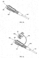
- FIG. 2a shows an optical fiber connector 10 in the present invention.
- the optical fiber connector includes an optical fiber joint 100, an optical fiber joint 300, and an optical fiber adapter 200.
- the optical fiber joint 100 is connected to the optical fiber joint 300 by using the optical fiber adapter 200, implementing interconnection of internal optical fibers.
- FIG. 2b is a schematic diagram of the optical fiber joint 100.
- the optical fiber joint 100 includes an optical fiber 110, an inner sleeve element 140, and an outer sleeve element 130.
- the inner sleeve element 140 has a cavity inside, where an optical fiber extending out of the optical cable 110 is held in the cavity, one end of the inner sleeve element 140 is fixed at the optical cable 110, and a sleeve 180 is placed at the other end.
- the outer sleeve element 130 is sleeved onto an outer side of the inner sleeve element 140, and the outer sleeve element 130 is capable of axially rotating around the sleeve 180.
- the sleeve 180 of the inner sleeve element 140 at least partially protrudes out of the outer sleeve element 130, and a tail end of the sleeve 180 protruding out of the outer sleeve element 130 has an opening, so that the tail end of the sleeve 180 forms a C-shaped section.
- the sleeve with the C-shaped opening may be seamlessly connected to a C-shaped slot of the optical fiber adapter. In this way, blind insertion of the optical fiber joint is implemented, and the operation is simpler, thereby implementing plug and play of the optical fiber connector.
- the sleeve 180 may be a cylindrical sleeve, or an elliptical sleeve, or a sleeve in another shape.
- the embodiment of the present invention uses a cylindrical sleeve 180 as an example. From the perspective reverse to the axial direction of the sleeve 180, the C-shaped opening of the sleeve 180 is a circle or an ellipse with an opening.
- the C-shaped tail end of the sleeve 180 is configured to connect to a C-shaped slot 2012 of an optical fiber adapter 200 that matches the optical fiber joint 100.
- the opening of the sleeve 180 is configured to connect to a locating key 2014 of the optical fiber adapter 200 that matches the optical fiber joint 100.
- the sleeve is configured to connect to the slot 2012 of the optical fiber adapter 200 that matches the optical fiber joint 100, where the C-shaped section at the tail end of the sleeve matches a C-shaped section of the slot 2012 of the optical fiber adapter 200.
- the opening of the sleeve 180 is horn-shaped.
- An opening angle of the horn-shaped opening of the sleeve 180 is equal to or larger than 10 degrees, and is smaller than or equal to 30 degrees.
- the opening angle of the horn-shaped opening of the sleeve 180 is 15 degrees or 22.5 degrees.
- the outer sleeve element 130 is a step-shaped circular tube structure, an inner surface of which has two protruding locking points 1304 (not shown in FIG. 3a , reference may be made to 1304 in FIG. 4 and FIG. 5 ).
- the locking points 1304 are fastened to a second sliding slot 2015 (not shown in FIG. 3a , reference may be made to 2015 in FIG. 5a ) on an adapter component 210, thereby implementing locking connection.
- An external front end of the outer sleeve element 130 has an arrow alignment identifier for indicating connection and disconnection states of the connector; and a rear end of the outer sleeve element 130 has symmetric cut planes, and there are vertical shallow grooves in the planes to enhance operation feeling.
- the optical fiber joint 100 further includes a tail ferrule 120, an insertion core 150, and a rope 160, and a joint dust-proof cap 170.
- Symmetric second sliding slots 1704 are placed on an outer surface of the joint dust-proof cap 170, and the joint dust-proof cap 170 is equipped with an O-shaped sealing ring 172.
- the joint dust-proof cap 170 is tied to the body of the optical fiber joint 100 by using the rope 160.
- FIG. 3b is an exploded diagram of an optical fiber joint
- FIG. 3c is a sectional diagram of the optical fiber joint.
- the optical fiber joint 100 includes a ferrule 122, a snap ring 126, an O-shaped sealing ring 132, an O-shaped sealing ring 136, an O-shaped sealing ring 172, an elastic component 134, and a connecting piece 138.
- the insertion core 150, the connecting piece 138, the elastic component 134, and the outer sleeve element 130 are sequentially sleeved onto the optical cable 110.
- the insertion core 150 is sleeved onto the optical cable 110.
- the insertion core 150 is a circular cylinder having a plurality of steps.
- the optical cable 110 passes through the insertion core 150.
- the insertion core 150 includes two oppositely arranged ends 150a and 150b, and the optical cable 110 is exposed at the end 150b that is of the insertion core 150 and far from the connecting piece 138.
- the connecting piece 138 is sleeved onto the end 150a of the insertion core 150.
- Inner aramid yarn of the optical cable 110 is fastened to the connecting piece 138 by using the snap ring 126.
- the tail ferrule 120 may be prefabricated and finally sleeved onto the optical cable, or may be cast in an integral injection manner.
- the connecting piece 138 includes two oppositely arranged ends 138a and 138b.
- the end 138a of the connecting piece 138 is thread-connected to the end 150b of the insertion core 150.
- the other end 138b of the connecting piece 138 is fixed at outer aramid yarn of the optical cable 110 by using the snap ring 126.
- the end 138a of the connecting piece 138 is sleeved with O-shaped sealing rings 132 and 136 for purpose of sealing.
- the end 138a of the connecting piece 138 includes a shaft shoulder 138c.
- the shaft shoulder 138c is configured to abut against the elastic component 134.
- the elastic component 134 includes two oppositely arranged ends 134a and 134b.
- the end 134a of the elastic component 134 abuts against the end 138a that is of the connecting piece 138 and close to the insertion core 150.
- the elastic component 134 is a spring, and the elastic component 134 is sleeved onto the connecting piece 138.
- the end 134a of the elastic component 134 abuts against the shaft shoulder 138c of the connecting piece 138.
- the outer sleeve element 130 includes two oppositely arranged ends 130a and 130b.
- the outer sleeve element 130 is sleeved onto the connecting piece 138 and the insertion core 150.
- the end 130a of the outer sleeve element 130 is slidingly connected to the connecting piece 138, and abuts against the end 134b of the elastic component 134.
- the elastic component 134 is configured to provide elasticity against the insertion core 150 for the outer sleeve element 130, thereby preventing a loose connection.
- Symmetric locking points 1304 (referring to 1304 in FIG. 4a and FIG. 4b ) are placed in an inner wall of the end 130b of the outer sleeve element 130, and the locking points 1304 are cylindrical projections.
- the outer sleeve element 130 is a circular cylinder having steps.
- the end 130a of the outer sleeve element 130 inwardly forms a flange 130d configured to abut against the end 134b of the elastic component 134.
- the elastic component 134 is clamped between the flange 130d and the shaft shoulder 138c.
- Two opposite locking points 1304 are placed in an inner wall of the end 130b of the outer sleeve element 130, and the locking points 1304 are cylindrical projections.
- a plurality of locking points 1304 may be arranged along the circumference of the outer sleeve element 130.
- An outer surface of the other end 130b of the outer sleeve element 130 has an arrow alignment identifier for indicating connection and disconnection states of the optical fiber connector 10.
- An outer surface of the outer sleeve element 130 has symmetric cut planes, and there are vertical shallow grooves in the planes to enhance operation feeling.
- the inner sleeve element 140 extends along an axial direction of the insertion core 150, where the end 150b that is of the insertion core 150 and far from the connecting piece 138 is held in the inner sleeve element 140.
- one end of the inner sleeve element 140 is fixed at a snap ring, where the snap ring is sleeved onto the end 150b of the insertion core 150.
- the inner sleeve element 140 has a sleeve protruding forward, the sleeve is C-shaped, and protrudes out of a ceramic insertion core end face of the insertion core 150, so as to implement a protection function for the insertion core, prevent contamination to the insertion core end face due to contact with other components during inserting and removing operations of the optical fiber joint, or protect the insertion core from damage due to a drop.
- the sleeve has a horn-shaped opening, where the horn-shaped opening is configured to socket into the locating key 2014 (referring to FIG. 5a ) on the optical fiber adapter 200 when the optical fiber joint 100 is inserted into the optical fiber adapter 200, so that the optical fiber joint 100 is accurately aligned with the optical fiber adapter 200.
- an opening angle of the horn-shaped opening is equal to or larger than 10 degrees, and is smaller than or equal to 30 degrees.
- the opening angle is an angle formed between a direction along the axial direction of the sleeve and an edge direction of the horn-shaped opening, as shown in FIG. 6 , which may be specifically 10 degrees, 15 degrees, 22.5 degrees, or 30 degrees.
- the end 130b of the outer sleeve element 130 is fixed at and sealed with the optical cable 110 by using the ferrule 122.
- the tail ferrule 120 is sleeved onto the ferrule 122, and is fixed by using the snap ring 126, thereby enhancing tensile intensity and sealing performance of the optical fiber joint 100.
- the tail ferrule 120 may be prefabricated and finally sleeved onto the optical cable, or may be cast in an integral injection manner.
- the optical fiber joint 100 includes a joint dust-proof cap 170.
- the joint dust-proof dust 170 is tied on the optical fiber joint 100 by using the rope 160.
- a joint holding cavity is placed at one end of the joint dust-proof cap 170, where the joint holding cavity extends axially along the joint dust-proof cap 170, and the joint holding cavity holds the insertion core 150 and the inner sleeve element 140.
- the joint dust-proof cap 170 has the O-shaped sealing ring 172.
- At least one first sliding slot 1704 is arranged on the periphery of the joint dust-proof cap 170, where the number of sliding slots 1704 is equal to the number of locking points 1304 (referring to FIG. 4a and FIG 4b for the locking points 1304).
- the sliding slot 1704 cooperates with the locking point 1304 of the outer sleeve element 130, where the sliding slot 1704 is in a spiral shape, the sliding slot 1704 extends from one end of the joint dust-proof cap 170 to circumference of the joint dust-proof cap 170, and the extended tail end of the sliding slot 1704 is fastened to the locking point 1304.
- the extended tail end of the sliding slot 1704 is in an arc shape matching the shape of the locking point 1304.
- An outer surface of the joint dust-proof cap 170 has an arrow identifier and identifiers "0" and "1".
- the arrow identifier on the outer sleeve element 130 aligns with the arrow identifier on the joint dust-proof cap 170.
- the joint dust-proof cap 170 is turned towards the direction of "0"
- the optical fiber joint 100 enters a locking state
- the joint dust-proof cap 170 is turned towards the direction of "1”
- the optical fiber joint 100 enters a release state.
- a double locking manner is used, thereby ensuring long and reliable optical performance of the optical fiber connector.
- the joint dust-proof cap 170 When the joint dust-proof cap 170 is fastened to the optical fiber joint 100, the insertion core 150 and the inner sleeve element 140 are inserted into the holding cavity.
- the locking point 1304 of the optical fiber joint 100 slides into the sliding slot 1704 of the joint dust-proof cap 170, and the joint dust-proof cap 170 is turned from the direction of "1" to the direction of "0", so that the locking point 1304 slides to the tail end of the sliding slot 1704, thereby implementing locking.
- the joint dust-proof cap 170 is fastened to the optical fiber joint 100.
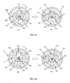
- FIG. 4a and FIG. 4b are front projection diagrams of the optical fiber joint 100, where an internal fastener unlocking structure of the optical fiber joint 100 is illustrated.
- FIG 4a illustrates an internal unlocking structure when the insertion core 150 does not have a snap-lock wing.
- the left part (a) in FIG. 4a illustrates an initial state of the inner fastener of the optical fiber joint 100
- the right part (b) in FIG. 4a illustrates a locked state of the inner fastener of the optical fiber joint 100
- FIG 4b illustrates an internal unlocking structure when the insertion core 150 has a snap-lock wing.
- the left part (a) in FIG. 4b illustrates an initial state of the inner fastener of the optical fiber joint 100
- the right part (b) in FIG 4b illustrates a locked state of the inner fastener of the optical fiber joint 100.
- an inner surface of the outer sleeve element 130 has a sloped boss 1302.
- the sloped boss 1302 bypasses the snap-lock wing 1502 on the insertion core 150, and in this case, the snap-lock wing 1502 is fastened to a snap on the socket 201 (referring to FIG 5a ), thereby implementing connection and locking.
- the insertion core 150 that does not have a snap-lock wing may also be adopted, and in this case, the inner surface of the outer sleeve element 130 does not have a corresponding sloped boss.
- the two symmetric locking points 1304 on the inner surface of the outer sleeve element 130 are fastened to the two symmetric second sliding slots 2015 on the outer surface of the socket 201 (referring to FIG. 5a ), thereby implementing double locking and connection.
- the outer sleeve element 130 is turned to change from the state illustrated in the left part (a) in FIG. 4b to the state illustrated in the right part (b) in FIG. 4b .
- the snap-lock wing 1502 on the insertion core 150 is pressed down by the sloped boss 1302 of the outer sleeve element 130, thereby implementing fastening unlocking.
- the two symmetric locking points 1304 on the inner surface of the outer sleeve element 130 are also turned and released from the two symmetric second sliding slots 2015 on the outer surface of the socket 201, and in this case, the optical fiber joint 100 may be removed from the optical fiber adapter 200.
- the outer sleeve element 130 may be turned by 45 degrees to implement a process of locking and unlocking of the connector.
- a limiting column 1504 is arranged on the insertion core 150, and left and right limiting stages 1306 are designed on the outer sleeve element 130.
- the limiting column 1504 is limited by the left limiting stage 1306 and cannot be turned further; and when the connector is in the released state as illustrated in the right part (b) in FIG. 4b , the limiting column 1504 is limited by the right limiting stage 1306 and cannot be turned further.
- FIG. 5a is a schematic structural diagram of the optical fiber adapter 200.
- FIG 5b is an exploded diagram of the optical fiber adapter 200. As shown in FIG. 5a and FIG. 5b , the socket 201 is placed at one end of the optical fiber adapter 200.
- a socket 202 may be further placed at the other end of the optical fiber adapter 200.
- the two sockets 201 and 202, and the ceramic ferrule 212 that is arranged at the center of the adapter may be welded together using ultrasound.
- the socket 201 has the cavity 2011 and the slot 2012, where the cavity 2011 is located at the middle part of the socket 201, and the cavity 2011 and the slot 2012 axially extends along the socket 201.
- the slot 2012 surrounds the periphery of the cavity 2011.
- the cavity 2011 cooperates with the insertion core 150
- the slot 2012 cooperates with the inner sleeve element 140
- a locating key 2014 is placed in the slot 2012.
- the locating key 2014 is a strip-like projection extending axially along the socket 201, so that the slot 2012 forms a C-shaped section and seamlessly connects to the sleeve that has a C-shaped opening in the optical fiber joint. In this way, blind insertion of the optical fiber joint may be implemented, and the operation is simpler, thereby implementing plug and play of the optical fiber connector.
- the C-shaped slot 2012 is a circle or an ellipse with an opening.
- the C-shaped inner sleeve element cooperates with the locating key 2014, and is inserted into the slot 2012.
- the sockets 201 and 202 are cylindrical.
- the cavity 210 is a square cavity or a circular cavity.
- the slot 2012 is a C-shaped slot.
- the slot 2012 that has a C-shaped section is configured to hold a C-shaped tail end of the sleeve 180 of the optical fiber joint 100 that matches the optical fiber adapter 200.
- the locating key 2014 is configured to connect to the opening of the sleeve of the optical fiber joint 100 that matches the optical fiber adapter 200.
- the width of the locating key 2014 is equivalent to the width of the opening of the sleeve 180 of the optical fiber joint 100.
- the second sliding slot 2015 is placed on the periphery of the socket 201, where the second sliding slot 2015 is in a spiral shape, and the second sliding slot 2015 circumferentially extends along the socket from one end of the socket 201, and the tail end to which the second sliding slot 2015 extends is fastened to the locking point 1304.
- the second sliding slot 2015 is in the same shape as the sliding slot 1704 (referring to FIG. 3a ) of the joint dust-proof cap 170.
- the optical fiber adapter 200 includes an O-shaped sealing ring 222, a locking nut 220, an O-shaped sealing ring 240, a socket body 210, and a ceramic ferrule 212.
- the O-shaped sealing ring 240, the locking nut 220, and the O-shaped sealing ring 240 are sequentially sleeved onto the socket body 210, and the ceramic ferrule 212 is inserted into the other end of the socket body 210, and is fixed by using the O-shaped sealing ring 222.
- the optical fiber adapter 200 includes an adapter dust-proof cap 230, where one end of the adapter dust-proof cap 230 has an adapter holding cavity for holding the optical fiber adapter 200.
- the holding cavity is configured to hold the socket 201 when the optical fiber adapter 200 is inserted into the dust-proof cap 230.
- the horn-shaped opening of the sleeve of the inner sleeve element 140 is targeted at and inserted into the locating key 2014 in the sliding slot
- the inner sleeve element 140 is inserted into the sliding slot 2012 so that the insertion core 150 is inserted into the cavity 2011,
- the locking point 1304 of the optical fiber joint slides into the second sliding slot 2015 of the optical fiber adapter, and the optical fiber socket 201 is turned so that the locking point 1304 slides to the tail end of the second sliding slot 2015, thereby implementing locking.
- the optical fiber connector provided by this embodiment of the present invention is seamlessly connected to the C-shaped slot of the optical fiber adapter by using the sleeve having the C-shaped opening of the optical fiber joint. In this way, blind insertion of the optical fiber joint may be implemented, and the operation is simpler, thereby implementing plug and play of the optical fiber connector.
- the optical fiber connector provided by the embodiment of the present invention further achieves the highest water-proof grade.
Landscapes
- Physics & Mathematics (AREA)
- General Physics & Mathematics (AREA)
- Optics & Photonics (AREA)
- Mechanical Coupling Of Light Guides (AREA)
Claims (10)
- Optikfaserverbindung (100), die Folgendes umfasst:ein optisches Kabel (110);einen Einführungskern (150), der auf das optische Kabel (110) aufgeschoben ist;ein Verbindungsstück (138), das auf den Einführungskern (150) aufgeschoben ist, wobei das optische Kabel (110) durch den Einführungskern (150) hindurchläuft, der Einführungskern ein gegenüberliegend angeordnetes erstes und zweites Ende (150a, 150b) beinhaltet und das optische Kabel (110) an dem ersten Ende (150b) des Einführungskerns (150) weit entfernt von dem Verbindungsstück (138) freigelegt ist, das Verbindungsstück (138) auf das zweite Ende (150a) des Einführungskerns (150) aufgeschoben ist;ein Innenhüllenelement (140) mit einem Hohlraum darin, wobei eine optische Faser, die sich aus dem optischen Kabel (110) heraus erstreckt, in dem Hohlraum gehalten wird, ein Ende des Innenhüllenelements (140) an dem optischen Kabel (110) befestigt ist und eine Hülle (180) an dem anderen Ende des Innenhüllenelements (140) platziert ist, wobei sich das Innenhüllenelement (140) entlang einer Axialrichtung des Einführungskerns (150) erstreckt, wobei das erste Ende (150b) des Einführungskerns (150) weit entfernt von dem Verbindungsstück (138) in dem Innenhüllenelement (140) gehalten wird; undein Außenhüllenelement (130), das auf das Verbindungsstück (138) und den Einführungskern (150) aufgeschoben ist, wobei das Außenhüllenelement (130) auf eine Außenseite des Innenhüllenelements (140) aufgeschoben ist und das Außenhüllenelement (130) zum axialen Rotieren um die Hülle (180) fähig ist;wobei die Hülle (180) des Innenhüllenelements (140) wenigstens teilweise aus dem Außenhüllenelement (130) herausragt und ein hinteres Ende der Hülle (180), das aus dem Außenhüllenelement (130) herausragt, eine Öffnung aufweist, so dass das hintere Ende der Hülle (180) einen C-förmigen Abschnitt bildet,wobei ein Ende des Verbindungsstücks (138) eine Schaftschulter (138c), eine elastische Komponente (134), die auf das Verbindungsstück (138) aufgeschoben ist, aufweist,wobei die Schaftschulter (138c) dazu konfiguriert ist, gegen ein Ende (134a) der elastischen Komponente (134) zu stoßen;wobei ein Ende (130a) des Außenhüllenelements (130) gleitend mit dem Verbindungsstück (138) verbunden ist und nach innen einen Flansch (130d) bildet, der gegen das andere Ende (134b) der elastischen Komponente (134) stößt, wobei die elastische Komponente (134) zwischen den Flansch (130d) und die Schaftschulter (138c) geklemmt ist und dazu konfiguriert ist, eine Elastizität entgegen des Einführungskerns (150) für das Außenhüllenelement (130) bereitzustellen, um eine lockere Verbindung zu verhindern,wobei die Öffnung des C-förmigen hinteren Endes der Hülle (180) hornförmig ist;wobei ein externes Ende des Außenhüllenelements (130) eine Pfeilausrichtungskennzeichnung zum Anzeigen von einem Verbindungs- und einem Trennungszustand aufweist.
- Optikfaserverbindung (100) nach Anspruch 1, wobei das C-förmige hintere Ende der Hülle (180) dazu konfiguriert ist, mit einem C-förmigen Schlitz (2012) des Optikfaseradapters (200) verbunden zu werden, der mit der Optikfaserverbindung (100) zusammenpasst.
- Optikfaserverbindung (100) nach Anspruch 1 oder 2, wobei die Öffnung der Hülle (180) dazu konfiguriert ist, mit einem Lokalisierungsschlüssel (2014) des Optikfaseradapters (200) verbunden zu werden, der mit der Optikfaserverbindung (100) zusammenpasst.
- Optikfaserverbindung (100) nach einem der Ansprüche 1 bis 3, wobei die Hülle (180) dazu konfiguriert ist, mit einem Schlitz (2012) des Optikfaseradapters (200) verbunden zu werden, der mit der Optikfaserverbindung (100) zusammenpasst, wobei der C-förmige Abschnitt an dem hinteren Ende der Hülle (180) mit einem C-förmigen Abschnitt des Schlitzes (2012) des Optikfaseradapters (200) zusammenpasst.
- Optikfaserverbindung (100) nach einem der Ansprüche 1 bis 3, wobei ein Öffnungswinkel der hornförmigen Öffnung der Hülle (180) gleich oder größer als 10 Grad ist und kleiner als oder gleich 30 Grad ist.
- Optikfaserverbindung (100) nach Anspruch 5, wobei der Öffnungswinkel der hornförmigen Öffnung der Hülle (180) 15 Grad oder 22,5 Grad beträgt.
- Optikfaserverbinder (10), der die Optikfaserverbindung (100) nach einem der Ansprüche 1-6 und einen Optikfaseradapter (200) umfasst, wobei
die Hülle (180), die eine C-förmige Öffnung aufweist, mit einem C-förmigen Schlitz (2012) des Optikfaseradapters (200) verbunden ist; und
der Optikfaseradapter (200) Folgendes umfasst:
einen Sockel (201), der an einem Ende des Optikfaseradapters (200) platziert ist, wobei ein Hohlraum (2011), der zum Empfangen einer optischen Faser konfiguriert ist, und ein Schlitz (2012) in dem Sockel (201) platziert sind, wobei sich der Hohlraum (2011) in einem mittleren Teil des Sockels (201) befindet und dazu konfiguriert ist, mit dem Einführungskern (150) zusammenzuwirken, der Schlitz (2012) eine Peripherie des Hohlraums (2011) umgibt und ein Lokalisierungsschlüssel (2014) in dem Sockel (201) platziert ist, so dass der Schlitz (2012) einen C-förmigen Abschnitt bildet. - Optikfaserverbinder (10) nach Anspruch 7, wobei eine Innenwand des Außenhüllenelements (130) der Optikfaserverbindung (100) wenigstens eine Ausbuchtung (1304) aufweist.
- Optikfaserverbinder (10) nach Anspruch 7, wobei wenigstens ein Gleitschlitz (2015) auf einer Außenoberfläche des Sockels (201) des Optikfaseradapters (200) platziert ist.
- Optikfaserverbinder (10) nach Anspruch 8 oder 9, wobei die Optikfaserverbindung (100) in den Optikfaseradapter (200) eingeführt ist und die Ausbuchtung (1304) mit dem Gleitschlitz (2015) verbunden ist.
Priority Applications (3)
| Application Number | Priority Date | Filing Date | Title |
|---|---|---|---|
| PL18169537T PL3418786T3 (pl) | 2013-11-12 | 2013-11-12 | Złącze światłowodowe i łącznik światłowodowy |
| ES18169537T ES2801330T3 (es) | 2013-11-12 | 2013-11-12 | Unión de fibra óptica y conector de fibra óptica |
| EP18169537.0A EP3418786B1 (de) | 2013-11-12 | 2013-11-12 | Glasfaserverbindung und glasfaserstecker |
Applications Claiming Priority (3)
| Application Number | Priority Date | Filing Date | Title |
|---|---|---|---|
| EP13823910.8A EP2894501B1 (de) | 2013-11-12 | 2013-11-12 | Faseroptischer verbinder und faseroptische verbindung |
| EP18169537.0A EP3418786B1 (de) | 2013-11-12 | 2013-11-12 | Glasfaserverbindung und glasfaserstecker |
| PCT/CN2013/086983 WO2015070382A1 (zh) | 2013-11-12 | 2013-11-12 | 光纤连接头、光纤适配器及光纤连接器 |
Related Parent Applications (1)
| Application Number | Title | Priority Date | Filing Date |
|---|---|---|---|
| EP13823910.8A Division EP2894501B1 (de) | 2013-11-12 | 2013-11-12 | Faseroptischer verbinder und faseroptische verbindung |
Publications (2)
| Publication Number | Publication Date |
|---|---|
| EP3418786A1 EP3418786A1 (de) | 2018-12-26 |
| EP3418786B1 true EP3418786B1 (de) | 2020-04-29 |
Family
ID=53056605
Family Applications (2)
| Application Number | Title | Priority Date | Filing Date |
|---|---|---|---|
| EP18169537.0A Active EP3418786B1 (de) | 2013-11-12 | 2013-11-12 | Glasfaserverbindung und glasfaserstecker |
| EP13823910.8A Active EP2894501B1 (de) | 2013-11-12 | 2013-11-12 | Faseroptischer verbinder und faseroptische verbindung |
Family Applications After (1)
| Application Number | Title | Priority Date | Filing Date |
|---|---|---|---|
| EP13823910.8A Active EP2894501B1 (de) | 2013-11-12 | 2013-11-12 | Faseroptischer verbinder und faseroptische verbindung |
Country Status (14)
| Country | Link |
|---|---|
| US (1) | US9557493B2 (de) |
| EP (2) | EP3418786B1 (de) |
| JP (1) | JP5977459B2 (de) |
| KR (2) | KR102067453B1 (de) |
| CN (2) | CN105339822B (de) |
| AU (1) | AU2013304616B2 (de) |
| BR (1) | BR112016010663B1 (de) |
| CA (1) | CA2885821C (de) |
| ES (1) | ES2801330T3 (de) |
| MX (1) | MX342434B (de) |
| PL (1) | PL3418786T3 (de) |
| RU (1) | RU2644027C2 (de) |
| TW (1) | TWI554798B (de) |
| WO (1) | WO2015070382A1 (de) |
Families Citing this family (23)
| Publication number | Priority date | Publication date | Assignee | Title |
|---|---|---|---|---|
| BR112017012958B1 (pt) | 2014-12-25 | 2019-04-30 | Huawei Technologies Co., Ltd. | Peça de conexão e conector de fibra óptica |
| AU2016424753B2 (en) * | 2016-09-30 | 2020-05-07 | Huawei Technologies Co., Ltd. | Optical fiber plug, optical fiber adapter, and optical fiber connector assembly |
| JP7229329B2 (ja) * | 2016-09-30 | 2023-02-27 | 華為技術有限公司 | 光ファイバプラグ、光ファイバアダプタおよび光ファイバコネクタアセンブリ |
| CN106873085B (zh) * | 2017-01-22 | 2019-06-07 | 中航光电科技股份有限公司 | 光纤适配器 |
| LU100281B1 (de) * | 2017-06-09 | 2018-12-18 | Highyag Lasertechnologie Gmbh | Aufnahme für Lichtleiterstecker |
| CN207965231U (zh) * | 2017-11-14 | 2018-10-12 | 烽火通信科技股份有限公司 | 一种光纤连接头、光纤连接器插座和光纤连接组件 |
| CN109975928A (zh) * | 2017-12-27 | 2019-07-05 | 华为技术有限公司 | 光纤连接头、光纤适配器及光纤连接器 |
| WO2019157660A1 (zh) * | 2018-02-13 | 2019-08-22 | 华为技术有限公司 | 光纤连接头、光纤适配器和光纤连接装置 |
| CN108459378B (zh) * | 2018-02-22 | 2024-02-13 | 宁波市金泽通信设备有限公司 | 一种光纤连接器 |
| MX2020005467A (es) * | 2018-03-30 | 2020-09-07 | Fiberhome Telecommunication Tech Co Ltd | Conector de fibra optica y montaje de conexion optico. |
| CN109188611B (zh) * | 2018-09-03 | 2020-08-07 | 华为技术有限公司 | 一种光纤连接头及光纤连接器 |
| US11131812B2 (en) | 2018-10-29 | 2021-09-28 | Boxfish Research Limited | Fibre connector and method of assembly |
| WO2020092480A1 (en) * | 2018-10-30 | 2020-05-07 | Commscope Technologies Llc | Adapter for cable gland and cable gland unit |
| US11921329B2 (en) | 2019-02-12 | 2024-03-05 | Commscope Technologies Llc | Fiber optic connectors and fiber optic connection systems |
| CN110203768B (zh) * | 2019-06-14 | 2020-11-17 | 国网新疆电力有限公司博尔塔拉供电公司 | 电力光缆接续固定装置 |
| TWM585910U (zh) * | 2019-06-25 | 2019-11-01 | 大陸商安費諾光纖技術(深圳)有限公司 | 光纖連接器 |
| CN110542952B (zh) * | 2019-07-26 | 2021-05-18 | 华为技术有限公司 | 一种光纤连接头以及光纤连接器 |
| EP4042216A4 (de) * | 2019-10-09 | 2023-10-25 | CommScope Technologies LLC | Lanzetten für telekommunikationsgerät mit anschlüssen und gegensteckverbindern |
| CN111308615B (zh) * | 2020-02-19 | 2021-10-01 | 华为技术有限公司 | 光纤连接器插头、光纤适配器和光纤连接器 |
| BR112022013473A2 (pt) * | 2020-02-21 | 2022-09-13 | Senko Advanced Components Inc | Conector óptico de fibra |
| CN113009643B (zh) * | 2021-05-26 | 2021-08-20 | 中天宽带技术有限公司 | 预制连接器、耦合器及预制连接器组件 |
| CN115201984B (zh) * | 2022-08-16 | 2023-12-29 | 浙江大学 | 一种模块化可用于监测和通信的海缆分支器 |
| CN116908967B (zh) * | 2023-09-11 | 2023-11-24 | 无限光通讯(深圳)有限公司 | 一种防水光纤连接器 |
Family Cites Families (29)
| Publication number | Priority date | Publication date | Assignee | Title |
|---|---|---|---|---|
| GB2154333B (en) * | 1984-01-25 | 1987-11-25 | Int Standard Electric Corp | Connector coupling for optical waveguides |
| JPS60128305U (ja) * | 1984-02-06 | 1985-08-28 | エスエムケイ株式会社 | 光フアイバコネクタ |
| US4595251A (en) * | 1985-02-01 | 1986-06-17 | Hughes Aircraft Company | Coupling mechanism for connectors |
| US4812009A (en) * | 1987-06-30 | 1989-03-14 | American Telephone And Telegraph Company, At&T Bell Laboratories | Optical fiber connector |
| US5067783A (en) * | 1990-10-16 | 1991-11-26 | At&T Bell Laboratories | Optical fiber connector buildout system |
| US5129023A (en) * | 1991-05-14 | 1992-07-07 | At&T Bell Laboratories | Optical fiber connector having enhanced provisions for interconnection and for prevention of optical and mechanical disconnection |
| US5297227A (en) * | 1993-03-18 | 1994-03-22 | The United States Of America As Represented By The Secretary Of The Navy | Disengagable adapter for an optical fiber connection |
| CN1241045C (zh) * | 1998-01-30 | 2006-02-08 | 西蒙公司 | 用来连接光纤的适配器 |
| JP3654063B2 (ja) * | 1999-07-12 | 2005-06-02 | ソニー株式会社 | 光コネクタ |
| US6371657B1 (en) * | 1999-12-07 | 2002-04-16 | Molex Incorporated | Alignment system for mating connectors |
| US6648520B2 (en) | 2001-09-28 | 2003-11-18 | Corning Cable Systems Llc | Fiber optic plug |
| US7467896B2 (en) | 2000-05-26 | 2008-12-23 | Corning Cable Systems Llc | Fiber optic drop cables and preconnectorized assemblies |
| CA2454438A1 (en) * | 2003-02-07 | 2004-08-07 | Hypertronics Corporation | Connecting device |
| US20050254757A1 (en) * | 2004-02-23 | 2005-11-17 | Ferretti Vincent E Iii | Connector port for network interface device |
| US20060045428A1 (en) * | 2004-08-24 | 2006-03-02 | Thomas Theuerkorn | Fiber optic receptacle and plug assemblies |
| US7234877B2 (en) * | 2004-10-27 | 2007-06-26 | Panduit Corp. | Fiber optic industrial connector |
| US7244066B2 (en) * | 2005-02-25 | 2007-07-17 | Corning Cable Systems Llc | Fiber optic receptacle and plug assembly including alignment sleeve insert |
| US7264402B2 (en) * | 2005-03-10 | 2007-09-04 | Corning Cable Systems Llc | Multi-fiber optic receptacle and plug assembly |
| JP4730274B2 (ja) * | 2006-09-29 | 2011-07-20 | ソニー株式会社 | 光結合器、光コネクタ及びレセプタクル型光伝送モジュール |
| JP2008102290A (ja) * | 2006-10-18 | 2008-05-01 | Fujikura Ltd | 光コネクタ、及び光コネクタ組立用のフレーム固定治具 |
| US7591595B2 (en) * | 2007-01-24 | 2009-09-22 | Adc Telelcommunications, Inc. | Hardened fiber optic adapter |
| US7708469B2 (en) | 2008-04-11 | 2010-05-04 | Corning Cable Systems Llc | Fiber optic connector assembly and method for venting gas inside a fiber optic connector sub-assembly |
| JP4577793B2 (ja) * | 2008-06-04 | 2010-11-10 | ヒロセ電機株式会社 | 防水コネクタ、及び、この防水コネクタを用いた防水装置 |
| JP5080600B2 (ja) * | 2010-02-26 | 2012-11-21 | 日本航空電子工業株式会社 | 光コネクタ内蔵プラグ |
| CN201788298U (zh) * | 2010-05-31 | 2011-04-06 | 深圳市华为安捷信电气有限公司 | 一种接头座、接头及连接机构 |
| CN102401941A (zh) * | 2010-09-10 | 2012-04-04 | 东侑光电股份有限公司 | 具有防尘功能的光纤连接器与光纤适配器 |
| JP5707808B2 (ja) * | 2010-09-21 | 2015-04-30 | 富士通株式会社 | 結合デバイス |
| KR101203509B1 (ko) * | 2011-11-21 | 2012-11-21 | 박찬설 | 광섬유 커넥터 |
| CN102870023B (zh) | 2012-06-26 | 2014-07-30 | 华为技术有限公司 | 光纤连接头、光纤适配器及光纤连接器 |
-
2013
- 2013-11-12 ES ES18169537T patent/ES2801330T3/es active Active
- 2013-11-12 KR KR1020187030430A patent/KR102067453B1/ko active IP Right Grant
- 2013-11-12 MX MX2015005893A patent/MX342434B/es active IP Right Grant
- 2013-11-12 BR BR112016010663-6A patent/BR112016010663B1/pt active IP Right Grant
- 2013-11-12 RU RU2016122887A patent/RU2644027C2/ru active
- 2013-11-12 WO PCT/CN2013/086983 patent/WO2015070382A1/zh active Application Filing
- 2013-11-12 CN CN201380002934.2A patent/CN105339822B/zh active Active
- 2013-11-12 KR KR1020167014631A patent/KR101912411B1/ko active IP Right Grant
- 2013-11-12 JP JP2015546824A patent/JP5977459B2/ja active Active
- 2013-11-12 PL PL18169537T patent/PL3418786T3/pl unknown
- 2013-11-12 EP EP18169537.0A patent/EP3418786B1/de active Active
- 2013-11-12 CN CN201710843141.3A patent/CN107656339B/zh active Active
- 2013-11-12 AU AU2013304616A patent/AU2013304616B2/en active Active
- 2013-11-12 CA CA2885821A patent/CA2885821C/en active Active
- 2013-11-12 EP EP13823910.8A patent/EP2894501B1/de active Active
-
2014
- 2014-02-26 US US14/191,174 patent/US9557493B2/en active Active
- 2014-04-17 TW TW103114092A patent/TWI554798B/zh active
Non-Patent Citations (1)
| Title |
|---|
| None * |
Also Published As
| Publication number | Publication date |
|---|---|
| TWI554798B (zh) | 2016-10-21 |
| JP5977459B2 (ja) | 2016-08-24 |
| KR20180117735A (ko) | 2018-10-29 |
| CN105339822A (zh) | 2016-02-17 |
| KR101912411B1 (ko) | 2018-10-26 |
| CA2885821A1 (en) | 2015-05-12 |
| AU2013304616A1 (en) | 2015-05-28 |
| PL3418786T3 (pl) | 2020-11-02 |
| EP3418786A1 (de) | 2018-12-26 |
| RU2644027C2 (ru) | 2018-02-07 |
| CN107656339A (zh) | 2018-02-02 |
| US9557493B2 (en) | 2017-01-31 |
| MX2015005893A (es) | 2015-09-10 |
| WO2015070382A1 (zh) | 2015-05-21 |
| CN105339822B (zh) | 2017-10-27 |
| ES2801330T3 (es) | 2021-01-11 |
| KR20160083044A (ko) | 2016-07-11 |
| EP2894501B1 (de) | 2018-05-02 |
| KR102067453B1 (ko) | 2020-01-17 |
| MX342434B (es) | 2016-09-29 |
| CA2885821C (en) | 2020-01-07 |
| CN107656339B (zh) | 2019-08-13 |
| RU2016122887A (ru) | 2017-12-18 |
| EP2894501A1 (de) | 2015-07-15 |
| US20150260926A1 (en) | 2015-09-17 |
| EP2894501A4 (de) | 2015-11-25 |
| BR112016010663B1 (pt) | 2019-03-26 |
| TW201518799A (zh) | 2015-05-16 |
| AU2013304616B2 (en) | 2015-09-03 |
| JP2015537255A (ja) | 2015-12-24 |
Similar Documents
| Publication | Publication Date | Title |
|---|---|---|
| EP3418786B1 (de) | Glasfaserverbindung und glasfaserstecker | |
| US10948660B2 (en) | Connecting piece and optical fiber connector | |
| US20190227244A1 (en) | Optical Fiber Plug, Optical Fiber Adapter, And Optical Fiber Connector Assembly | |
| CN110542952A (zh) | 一种光纤连接头以及光纤连接器 | |
| JP6337048B2 (ja) | 光ファイバージョイント、光ファイバーアダプタ、および光ファイバーコネクタ | |
| JP7229329B2 (ja) | 光ファイバプラグ、光ファイバアダプタおよび光ファイバコネクタアセンブリ |
Legal Events
| Date | Code | Title | Description |
|---|---|---|---|
| PUAI | Public reference made under article 153(3) epc to a published international application that has entered the european phase |
Free format text: ORIGINAL CODE: 0009012 |
|
| STAA | Information on the status of an ep patent application or granted ep patent |
Free format text: STATUS: THE APPLICATION HAS BEEN PUBLISHED |
|
| AC | Divisional application: reference to earlier application |
Ref document number: 2894501 Country of ref document: EP Kind code of ref document: P |
|
| AK | Designated contracting states |
Kind code of ref document: A1 Designated state(s): AL AT BE BG CH CY CZ DE DK EE ES FI FR GB GR HR HU IE IS IT LI LT LU LV MC MK MT NL NO PL PT RO RS SE SI SK SM TR |
|
| STAA | Information on the status of an ep patent application or granted ep patent |
Free format text: STATUS: REQUEST FOR EXAMINATION WAS MADE |
|
| 17P | Request for examination filed |
Effective date: 20190626 |
|
| RBV | Designated contracting states (corrected) |
Designated state(s): AL AT BE BG CH CY CZ DE DK EE ES FI FR GB GR HR HU IE IS IT LI LT LU LV MC MK MT NL NO PL PT RO RS SE SI SK SM TR |
|
| GRAP | Despatch of communication of intention to grant a patent |
Free format text: ORIGINAL CODE: EPIDOSNIGR1 |
|
| STAA | Information on the status of an ep patent application or granted ep patent |
Free format text: STATUS: GRANT OF PATENT IS INTENDED |
|
| RIC1 | Information provided on ipc code assigned before grant |
Ipc: G02B 6/38 20060101AFI20191119BHEP |
|
| INTG | Intention to grant announced |
Effective date: 20191209 |
|
| GRAS | Grant fee paid |
Free format text: ORIGINAL CODE: EPIDOSNIGR3 |
|
| GRAA | (expected) grant |
Free format text: ORIGINAL CODE: 0009210 |
|
| STAA | Information on the status of an ep patent application or granted ep patent |
Free format text: STATUS: THE PATENT HAS BEEN GRANTED |
|
| AC | Divisional application: reference to earlier application |
Ref document number: 2894501 Country of ref document: EP Kind code of ref document: P |
|
| AK | Designated contracting states |
Kind code of ref document: B1 Designated state(s): AL AT BE BG CH CY CZ DE DK EE ES FI FR GB GR HR HU IE IS IT LI LT LU LV MC MK MT NL NO PL PT RO RS SE SI SK SM TR |
|
| REG | Reference to a national code |
Ref country code: GB Ref legal event code: FG4D |
|
| REG | Reference to a national code |
Ref country code: CH Ref legal event code: EP |
|
| REG | Reference to a national code |
Ref country code: DE Ref legal event code: R096 Ref document number: 602013068610 Country of ref document: DE |
|
| REG | Reference to a national code |
Ref country code: AT Ref legal event code: REF Ref document number: 1264171 Country of ref document: AT Kind code of ref document: T Effective date: 20200515 |
|
| REG | Reference to a national code |
Ref country code: IE Ref legal event code: FG4D |
|
| REG | Reference to a national code |
Ref country code: NL Ref legal event code: MP Effective date: 20200429 |
|
| REG | Reference to a national code |
Ref country code: LT Ref legal event code: MG4D |
|
| PG25 | Lapsed in a contracting state [announced via postgrant information from national office to epo] |
Ref country code: GR Free format text: LAPSE BECAUSE OF FAILURE TO SUBMIT A TRANSLATION OF THE DESCRIPTION OR TO PAY THE FEE WITHIN THE PRESCRIBED TIME-LIMIT Effective date: 20200730 Ref country code: IS Free format text: LAPSE BECAUSE OF FAILURE TO SUBMIT A TRANSLATION OF THE DESCRIPTION OR TO PAY THE FEE WITHIN THE PRESCRIBED TIME-LIMIT Effective date: 20200829 Ref country code: SE Free format text: LAPSE BECAUSE OF FAILURE TO SUBMIT A TRANSLATION OF THE DESCRIPTION OR TO PAY THE FEE WITHIN THE PRESCRIBED TIME-LIMIT Effective date: 20200429 Ref country code: NO Free format text: LAPSE BECAUSE OF FAILURE TO SUBMIT A TRANSLATION OF THE DESCRIPTION OR TO PAY THE FEE WITHIN THE PRESCRIBED TIME-LIMIT Effective date: 20200729 Ref country code: PT Free format text: LAPSE BECAUSE OF FAILURE TO SUBMIT A TRANSLATION OF THE DESCRIPTION OR TO PAY THE FEE WITHIN THE PRESCRIBED TIME-LIMIT Effective date: 20200831 Ref country code: LT Free format text: LAPSE BECAUSE OF FAILURE TO SUBMIT A TRANSLATION OF THE DESCRIPTION OR TO PAY THE FEE WITHIN THE PRESCRIBED TIME-LIMIT Effective date: 20200429 Ref country code: FI Free format text: LAPSE BECAUSE OF FAILURE TO SUBMIT A TRANSLATION OF THE DESCRIPTION OR TO PAY THE FEE WITHIN THE PRESCRIBED TIME-LIMIT Effective date: 20200429 |
|
| REG | Reference to a national code |
Ref country code: AT Ref legal event code: MK05 Ref document number: 1264171 Country of ref document: AT Kind code of ref document: T Effective date: 20200429 |
|
| PG25 | Lapsed in a contracting state [announced via postgrant information from national office to epo] |
Ref country code: LV Free format text: LAPSE BECAUSE OF FAILURE TO SUBMIT A TRANSLATION OF THE DESCRIPTION OR TO PAY THE FEE WITHIN THE PRESCRIBED TIME-LIMIT Effective date: 20200429 Ref country code: HR Free format text: LAPSE BECAUSE OF FAILURE TO SUBMIT A TRANSLATION OF THE DESCRIPTION OR TO PAY THE FEE WITHIN THE PRESCRIBED TIME-LIMIT Effective date: 20200429 Ref country code: RS Free format text: LAPSE BECAUSE OF FAILURE TO SUBMIT A TRANSLATION OF THE DESCRIPTION OR TO PAY THE FEE WITHIN THE PRESCRIBED TIME-LIMIT Effective date: 20200429 Ref country code: BG Free format text: LAPSE BECAUSE OF FAILURE TO SUBMIT A TRANSLATION OF THE DESCRIPTION OR TO PAY THE FEE WITHIN THE PRESCRIBED TIME-LIMIT Effective date: 20200729 |
|
| PG25 | Lapsed in a contracting state [announced via postgrant information from national office to epo] |
Ref country code: AL Free format text: LAPSE BECAUSE OF FAILURE TO SUBMIT A TRANSLATION OF THE DESCRIPTION OR TO PAY THE FEE WITHIN THE PRESCRIBED TIME-LIMIT Effective date: 20200429 Ref country code: NL Free format text: LAPSE BECAUSE OF FAILURE TO SUBMIT A TRANSLATION OF THE DESCRIPTION OR TO PAY THE FEE WITHIN THE PRESCRIBED TIME-LIMIT Effective date: 20200429 |
|
| REG | Reference to a national code |
Ref country code: ES Ref legal event code: FG2A Ref document number: 2801330 Country of ref document: ES Kind code of ref document: T3 Effective date: 20210111 |
|
| PG25 | Lapsed in a contracting state [announced via postgrant information from national office to epo] |
Ref country code: EE Free format text: LAPSE BECAUSE OF FAILURE TO SUBMIT A TRANSLATION OF THE DESCRIPTION OR TO PAY THE FEE WITHIN THE PRESCRIBED TIME-LIMIT Effective date: 20200429 Ref country code: SM Free format text: LAPSE BECAUSE OF FAILURE TO SUBMIT A TRANSLATION OF THE DESCRIPTION OR TO PAY THE FEE WITHIN THE PRESCRIBED TIME-LIMIT Effective date: 20200429 Ref country code: DK Free format text: LAPSE BECAUSE OF FAILURE TO SUBMIT A TRANSLATION OF THE DESCRIPTION OR TO PAY THE FEE WITHIN THE PRESCRIBED TIME-LIMIT Effective date: 20200429 Ref country code: RO Free format text: LAPSE BECAUSE OF FAILURE TO SUBMIT A TRANSLATION OF THE DESCRIPTION OR TO PAY THE FEE WITHIN THE PRESCRIBED TIME-LIMIT Effective date: 20200429 Ref country code: AT Free format text: LAPSE BECAUSE OF FAILURE TO SUBMIT A TRANSLATION OF THE DESCRIPTION OR TO PAY THE FEE WITHIN THE PRESCRIBED TIME-LIMIT Effective date: 20200429 Ref country code: CZ Free format text: LAPSE BECAUSE OF FAILURE TO SUBMIT A TRANSLATION OF THE DESCRIPTION OR TO PAY THE FEE WITHIN THE PRESCRIBED TIME-LIMIT Effective date: 20200429 |
|
| REG | Reference to a national code |
Ref country code: DE Ref legal event code: R097 Ref document number: 602013068610 Country of ref document: DE |
|
| PG25 | Lapsed in a contracting state [announced via postgrant information from national office to epo] |
Ref country code: SK Free format text: LAPSE BECAUSE OF FAILURE TO SUBMIT A TRANSLATION OF THE DESCRIPTION OR TO PAY THE FEE WITHIN THE PRESCRIBED TIME-LIMIT Effective date: 20200429 |
|
| PLBE | No opposition filed within time limit |
Free format text: ORIGINAL CODE: 0009261 |
|
| STAA | Information on the status of an ep patent application or granted ep patent |
Free format text: STATUS: NO OPPOSITION FILED WITHIN TIME LIMIT |
|
| 26N | No opposition filed |
Effective date: 20210201 |
|
| PG25 | Lapsed in a contracting state [announced via postgrant information from national office to epo] |
Ref country code: SI Free format text: LAPSE BECAUSE OF FAILURE TO SUBMIT A TRANSLATION OF THE DESCRIPTION OR TO PAY THE FEE WITHIN THE PRESCRIBED TIME-LIMIT Effective date: 20200429 |
|
| PG25 | Lapsed in a contracting state [announced via postgrant information from national office to epo] |
Ref country code: MC Free format text: LAPSE BECAUSE OF FAILURE TO SUBMIT A TRANSLATION OF THE DESCRIPTION OR TO PAY THE FEE WITHIN THE PRESCRIBED TIME-LIMIT Effective date: 20200429 |
|
| REG | Reference to a national code |
Ref country code: CH Ref legal event code: PL |
|
| PG25 | Lapsed in a contracting state [announced via postgrant information from national office to epo] |
Ref country code: LU Free format text: LAPSE BECAUSE OF NON-PAYMENT OF DUE FEES Effective date: 20201112 |
|
| REG | Reference to a national code |
Ref country code: BE Ref legal event code: MM Effective date: 20201130 |
|
| PG25 | Lapsed in a contracting state [announced via postgrant information from national office to epo] |
Ref country code: CH Free format text: LAPSE BECAUSE OF NON-PAYMENT OF DUE FEES Effective date: 20201130 Ref country code: LI Free format text: LAPSE BECAUSE OF NON-PAYMENT OF DUE FEES Effective date: 20201130 |
|
| PG25 | Lapsed in a contracting state [announced via postgrant information from national office to epo] |
Ref country code: IE Free format text: LAPSE BECAUSE OF NON-PAYMENT OF DUE FEES Effective date: 20201112 |
|
| PG25 | Lapsed in a contracting state [announced via postgrant information from national office to epo] |
Ref country code: MT Free format text: LAPSE BECAUSE OF FAILURE TO SUBMIT A TRANSLATION OF THE DESCRIPTION OR TO PAY THE FEE WITHIN THE PRESCRIBED TIME-LIMIT Effective date: 20200429 Ref country code: CY Free format text: LAPSE BECAUSE OF FAILURE TO SUBMIT A TRANSLATION OF THE DESCRIPTION OR TO PAY THE FEE WITHIN THE PRESCRIBED TIME-LIMIT Effective date: 20200429 |
|
| PG25 | Lapsed in a contracting state [announced via postgrant information from national office to epo] |
Ref country code: MK Free format text: LAPSE BECAUSE OF FAILURE TO SUBMIT A TRANSLATION OF THE DESCRIPTION OR TO PAY THE FEE WITHIN THE PRESCRIBED TIME-LIMIT Effective date: 20200429 |
|
| PG25 | Lapsed in a contracting state [announced via postgrant information from national office to epo] |
Ref country code: BE Free format text: LAPSE BECAUSE OF NON-PAYMENT OF DUE FEES Effective date: 20201130 |
|
| P01 | Opt-out of the competence of the unified patent court (upc) registered |
Effective date: 20230524 |
|
| PGFP | Annual fee paid to national office [announced via postgrant information from national office to epo] |
Ref country code: FR Payment date: 20230929 Year of fee payment: 11 |
|
| PGFP | Annual fee paid to national office [announced via postgrant information from national office to epo] |
Ref country code: GB Payment date: 20231006 Year of fee payment: 11 |
|
| PGFP | Annual fee paid to national office [announced via postgrant information from national office to epo] |
Ref country code: ES Payment date: 20231212 Year of fee payment: 11 |
|
| PGFP | Annual fee paid to national office [announced via postgrant information from national office to epo] |
Ref country code: TR Payment date: 20231110 Year of fee payment: 11 Ref country code: IT Payment date: 20231010 Year of fee payment: 11 Ref country code: DE Payment date: 20230929 Year of fee payment: 11 |
|
| PGFP | Annual fee paid to national office [announced via postgrant information from national office to epo] |
Ref country code: PL Payment date: 20231016 Year of fee payment: 11 |