EP3418421A1 - Cermet powder, protective film-coated member and method for producing same, and electroplating-bath roll and method for producing same - Google Patents
Cermet powder, protective film-coated member and method for producing same, and electroplating-bath roll and method for producing same Download PDFInfo
- Publication number
- EP3418421A1 EP3418421A1 EP17753182.9A EP17753182A EP3418421A1 EP 3418421 A1 EP3418421 A1 EP 3418421A1 EP 17753182 A EP17753182 A EP 17753182A EP 3418421 A1 EP3418421 A1 EP 3418421A1
- Authority
- EP
- European Patent Office
- Prior art keywords
- coating
- roll
- cermet
- mass
- carbide particles
- Prior art date
- Legal status (The legal status is an assumption and is not a legal conclusion. Google has not performed a legal analysis and makes no representation as to the accuracy of the status listed.)
- Granted
Links
Images

Classifications
-
- C—CHEMISTRY; METALLURGY
- C23—COATING METALLIC MATERIAL; COATING MATERIAL WITH METALLIC MATERIAL; CHEMICAL SURFACE TREATMENT; DIFFUSION TREATMENT OF METALLIC MATERIAL; COATING BY VACUUM EVAPORATION, BY SPUTTERING, BY ION IMPLANTATION OR BY CHEMICAL VAPOUR DEPOSITION, IN GENERAL; INHIBITING CORROSION OF METALLIC MATERIAL OR INCRUSTATION IN GENERAL
- C23C—COATING METALLIC MATERIAL; COATING MATERIAL WITH METALLIC MATERIAL; SURFACE TREATMENT OF METALLIC MATERIAL BY DIFFUSION INTO THE SURFACE, BY CHEMICAL CONVERSION OR SUBSTITUTION; COATING BY VACUUM EVAPORATION, BY SPUTTERING, BY ION IMPLANTATION OR BY CHEMICAL VAPOUR DEPOSITION, IN GENERAL
- C23C4/00—Coating by spraying the coating material in the molten state, e.g. by flame, plasma or electric discharge
- C23C4/04—Coating by spraying the coating material in the molten state, e.g. by flame, plasma or electric discharge characterised by the coating material
- C23C4/06—Metallic material
-
- C—CHEMISTRY; METALLURGY
- C25—ELECTROLYTIC OR ELECTROPHORETIC PROCESSES; APPARATUS THEREFOR
- C25D—PROCESSES FOR THE ELECTROLYTIC OR ELECTROPHORETIC PRODUCTION OF COATINGS; ELECTROFORMING; APPARATUS THEREFOR
- C25D17/00—Constructional parts, or assemblies thereof, of cells for electrolytic coating
- C25D17/10—Electrodes, e.g. composition, counter electrode
-
- C—CHEMISTRY; METALLURGY
- C22—METALLURGY; FERROUS OR NON-FERROUS ALLOYS; TREATMENT OF ALLOYS OR NON-FERROUS METALS
- C22C—ALLOYS
- C22C29/00—Alloys based on carbides, oxides, nitrides, borides, or silicides, e.g. cermets, or other metal compounds, e.g. oxynitrides, sulfides
- C22C29/02—Alloys based on carbides, oxides, nitrides, borides, or silicides, e.g. cermets, or other metal compounds, e.g. oxynitrides, sulfides based on carbides or carbonitrides
- C22C29/06—Alloys based on carbides, oxides, nitrides, borides, or silicides, e.g. cermets, or other metal compounds, e.g. oxynitrides, sulfides based on carbides or carbonitrides based on carbides, but not containing other metal compounds
- C22C29/067—Alloys based on carbides, oxides, nitrides, borides, or silicides, e.g. cermets, or other metal compounds, e.g. oxynitrides, sulfides based on carbides or carbonitrides based on carbides, but not containing other metal compounds comprising a particular metallic binder
-
- C—CHEMISTRY; METALLURGY
- C22—METALLURGY; FERROUS OR NON-FERROUS ALLOYS; TREATMENT OF ALLOYS OR NON-FERROUS METALS
- C22C—ALLOYS
- C22C29/00—Alloys based on carbides, oxides, nitrides, borides, or silicides, e.g. cermets, or other metal compounds, e.g. oxynitrides, sulfides
- C22C29/02—Alloys based on carbides, oxides, nitrides, borides, or silicides, e.g. cermets, or other metal compounds, e.g. oxynitrides, sulfides based on carbides or carbonitrides
- C22C29/06—Alloys based on carbides, oxides, nitrides, borides, or silicides, e.g. cermets, or other metal compounds, e.g. oxynitrides, sulfides based on carbides or carbonitrides based on carbides, but not containing other metal compounds
- C22C29/08—Alloys based on carbides, oxides, nitrides, borides, or silicides, e.g. cermets, or other metal compounds, e.g. oxynitrides, sulfides based on carbides or carbonitrides based on carbides, but not containing other metal compounds based on tungsten carbide
-
- C—CHEMISTRY; METALLURGY
- C23—COATING METALLIC MATERIAL; COATING MATERIAL WITH METALLIC MATERIAL; CHEMICAL SURFACE TREATMENT; DIFFUSION TREATMENT OF METALLIC MATERIAL; COATING BY VACUUM EVAPORATION, BY SPUTTERING, BY ION IMPLANTATION OR BY CHEMICAL VAPOUR DEPOSITION, IN GENERAL; INHIBITING CORROSION OF METALLIC MATERIAL OR INCRUSTATION IN GENERAL
- C23C—COATING METALLIC MATERIAL; COATING MATERIAL WITH METALLIC MATERIAL; SURFACE TREATMENT OF METALLIC MATERIAL BY DIFFUSION INTO THE SURFACE, BY CHEMICAL CONVERSION OR SUBSTITUTION; COATING BY VACUUM EVAPORATION, BY SPUTTERING, BY ION IMPLANTATION OR BY CHEMICAL VAPOUR DEPOSITION, IN GENERAL
- C23C4/00—Coating by spraying the coating material in the molten state, e.g. by flame, plasma or electric discharge
- C23C4/04—Coating by spraying the coating material in the molten state, e.g. by flame, plasma or electric discharge characterised by the coating material
- C23C4/06—Metallic material
- C23C4/067—Metallic material containing free particles of non-metal elements, e.g. carbon, silicon, boron, phosphorus or arsenic
-
- C—CHEMISTRY; METALLURGY
- C23—COATING METALLIC MATERIAL; COATING MATERIAL WITH METALLIC MATERIAL; CHEMICAL SURFACE TREATMENT; DIFFUSION TREATMENT OF METALLIC MATERIAL; COATING BY VACUUM EVAPORATION, BY SPUTTERING, BY ION IMPLANTATION OR BY CHEMICAL VAPOUR DEPOSITION, IN GENERAL; INHIBITING CORROSION OF METALLIC MATERIAL OR INCRUSTATION IN GENERAL
- C23C—COATING METALLIC MATERIAL; COATING MATERIAL WITH METALLIC MATERIAL; SURFACE TREATMENT OF METALLIC MATERIAL BY DIFFUSION INTO THE SURFACE, BY CHEMICAL CONVERSION OR SUBSTITUTION; COATING BY VACUUM EVAPORATION, BY SPUTTERING, BY ION IMPLANTATION OR BY CHEMICAL VAPOUR DEPOSITION, IN GENERAL
- C23C4/00—Coating by spraying the coating material in the molten state, e.g. by flame, plasma or electric discharge
- C23C4/04—Coating by spraying the coating material in the molten state, e.g. by flame, plasma or electric discharge characterised by the coating material
- C23C4/06—Metallic material
- C23C4/073—Metallic material containing MCrAl or MCrAlY alloys, where M is nickel, cobalt or iron, with or without non-metal elements
-
- C—CHEMISTRY; METALLURGY
- C23—COATING METALLIC MATERIAL; COATING MATERIAL WITH METALLIC MATERIAL; CHEMICAL SURFACE TREATMENT; DIFFUSION TREATMENT OF METALLIC MATERIAL; COATING BY VACUUM EVAPORATION, BY SPUTTERING, BY ION IMPLANTATION OR BY CHEMICAL VAPOUR DEPOSITION, IN GENERAL; INHIBITING CORROSION OF METALLIC MATERIAL OR INCRUSTATION IN GENERAL
- C23C—COATING METALLIC MATERIAL; COATING MATERIAL WITH METALLIC MATERIAL; SURFACE TREATMENT OF METALLIC MATERIAL BY DIFFUSION INTO THE SURFACE, BY CHEMICAL CONVERSION OR SUBSTITUTION; COATING BY VACUUM EVAPORATION, BY SPUTTERING, BY ION IMPLANTATION OR BY CHEMICAL VAPOUR DEPOSITION, IN GENERAL
- C23C4/00—Coating by spraying the coating material in the molten state, e.g. by flame, plasma or electric discharge
- C23C4/04—Coating by spraying the coating material in the molten state, e.g. by flame, plasma or electric discharge characterised by the coating material
- C23C4/10—Oxides, borides, carbides, nitrides or silicides; Mixtures thereof
-
- C—CHEMISTRY; METALLURGY
- C23—COATING METALLIC MATERIAL; COATING MATERIAL WITH METALLIC MATERIAL; CHEMICAL SURFACE TREATMENT; DIFFUSION TREATMENT OF METALLIC MATERIAL; COATING BY VACUUM EVAPORATION, BY SPUTTERING, BY ION IMPLANTATION OR BY CHEMICAL VAPOUR DEPOSITION, IN GENERAL; INHIBITING CORROSION OF METALLIC MATERIAL OR INCRUSTATION IN GENERAL
- C23C—COATING METALLIC MATERIAL; COATING MATERIAL WITH METALLIC MATERIAL; SURFACE TREATMENT OF METALLIC MATERIAL BY DIFFUSION INTO THE SURFACE, BY CHEMICAL CONVERSION OR SUBSTITUTION; COATING BY VACUUM EVAPORATION, BY SPUTTERING, BY ION IMPLANTATION OR BY CHEMICAL VAPOUR DEPOSITION, IN GENERAL
- C23C4/00—Coating by spraying the coating material in the molten state, e.g. by flame, plasma or electric discharge
- C23C4/12—Coating by spraying the coating material in the molten state, e.g. by flame, plasma or electric discharge characterised by the method of spraying
- C23C4/123—Spraying molten metal
-
- C—CHEMISTRY; METALLURGY
- C23—COATING METALLIC MATERIAL; COATING MATERIAL WITH METALLIC MATERIAL; CHEMICAL SURFACE TREATMENT; DIFFUSION TREATMENT OF METALLIC MATERIAL; COATING BY VACUUM EVAPORATION, BY SPUTTERING, BY ION IMPLANTATION OR BY CHEMICAL VAPOUR DEPOSITION, IN GENERAL; INHIBITING CORROSION OF METALLIC MATERIAL OR INCRUSTATION IN GENERAL
- C23C—COATING METALLIC MATERIAL; COATING MATERIAL WITH METALLIC MATERIAL; SURFACE TREATMENT OF METALLIC MATERIAL BY DIFFUSION INTO THE SURFACE, BY CHEMICAL CONVERSION OR SUBSTITUTION; COATING BY VACUUM EVAPORATION, BY SPUTTERING, BY ION IMPLANTATION OR BY CHEMICAL VAPOUR DEPOSITION, IN GENERAL
- C23C4/00—Coating by spraying the coating material in the molten state, e.g. by flame, plasma or electric discharge
- C23C4/12—Coating by spraying the coating material in the molten state, e.g. by flame, plasma or electric discharge characterised by the method of spraying
- C23C4/129—Flame spraying
-
- C—CHEMISTRY; METALLURGY
- C23—COATING METALLIC MATERIAL; COATING MATERIAL WITH METALLIC MATERIAL; CHEMICAL SURFACE TREATMENT; DIFFUSION TREATMENT OF METALLIC MATERIAL; COATING BY VACUUM EVAPORATION, BY SPUTTERING, BY ION IMPLANTATION OR BY CHEMICAL VAPOUR DEPOSITION, IN GENERAL; INHIBITING CORROSION OF METALLIC MATERIAL OR INCRUSTATION IN GENERAL
- C23C—COATING METALLIC MATERIAL; COATING MATERIAL WITH METALLIC MATERIAL; SURFACE TREATMENT OF METALLIC MATERIAL BY DIFFUSION INTO THE SURFACE, BY CHEMICAL CONVERSION OR SUBSTITUTION; COATING BY VACUUM EVAPORATION, BY SPUTTERING, BY ION IMPLANTATION OR BY CHEMICAL VAPOUR DEPOSITION, IN GENERAL
- C23C4/00—Coating by spraying the coating material in the molten state, e.g. by flame, plasma or electric discharge
- C23C4/12—Coating by spraying the coating material in the molten state, e.g. by flame, plasma or electric discharge characterised by the method of spraying
- C23C4/134—Plasma spraying
-
- C—CHEMISTRY; METALLURGY
- C25—ELECTROLYTIC OR ELECTROPHORETIC PROCESSES; APPARATUS THEREFOR
- C25D—PROCESSES FOR THE ELECTROLYTIC OR ELECTROPHORETIC PRODUCTION OF COATINGS; ELECTROFORMING; APPARATUS THEREFOR
- C25D5/00—Electroplating characterised by the process; Pretreatment or after-treatment of workpieces
- C25D5/04—Electroplating with moving electrodes
-
- C—CHEMISTRY; METALLURGY
- C25—ELECTROLYTIC OR ELECTROPHORETIC PROCESSES; APPARATUS THEREFOR
- C25D—PROCESSES FOR THE ELECTROLYTIC OR ELECTROPHORETIC PRODUCTION OF COATINGS; ELECTROFORMING; APPARATUS THEREFOR
- C25D7/00—Electroplating characterised by the article coated
- C25D7/06—Wires; Strips; Foils
-
- C—CHEMISTRY; METALLURGY
- C25—ELECTROLYTIC OR ELECTROPHORETIC PROCESSES; APPARATUS THEREFOR
- C25D—PROCESSES FOR THE ELECTROLYTIC OR ELECTROPHORETIC PRODUCTION OF COATINGS; ELECTROFORMING; APPARATUS THEREFOR
- C25D7/00—Electroplating characterised by the article coated
- C25D7/06—Wires; Strips; Foils
- C25D7/0614—Strips or foils
- C25D7/0657—Conducting rolls
-
- B—PERFORMING OPERATIONS; TRANSPORTING
- B22—CASTING; POWDER METALLURGY
- B22F—WORKING METALLIC POWDER; MANUFACTURE OF ARTICLES FROM METALLIC POWDER; MAKING METALLIC POWDER; APPARATUS OR DEVICES SPECIALLY ADAPTED FOR METALLIC POWDER
- B22F7/00—Manufacture of composite layers, workpieces, or articles, comprising metallic powder, by sintering the powder, with or without compacting wherein at least one part is obtained by sintering or compression
- B22F7/06—Manufacture of composite layers, workpieces, or articles, comprising metallic powder, by sintering the powder, with or without compacting wherein at least one part is obtained by sintering or compression of composite workpieces or articles from parts, e.g. to form tipped tools
- B22F7/08—Manufacture of composite layers, workpieces, or articles, comprising metallic powder, by sintering the powder, with or without compacting wherein at least one part is obtained by sintering or compression of composite workpieces or articles from parts, e.g. to form tipped tools with one or more parts not made from powder
-
- Y—GENERAL TAGGING OF NEW TECHNOLOGICAL DEVELOPMENTS; GENERAL TAGGING OF CROSS-SECTIONAL TECHNOLOGIES SPANNING OVER SEVERAL SECTIONS OF THE IPC; TECHNICAL SUBJECTS COVERED BY FORMER USPC CROSS-REFERENCE ART COLLECTIONS [XRACs] AND DIGESTS
- Y10—TECHNICAL SUBJECTS COVERED BY FORMER USPC
- Y10T—TECHNICAL SUBJECTS COVERED BY FORMER US CLASSIFICATION
- Y10T428/00—Stock material or miscellaneous articles
- Y10T428/12—All metal or with adjacent metals
- Y10T428/12014—All metal or with adjacent metals having metal particles
-
- Y—GENERAL TAGGING OF NEW TECHNOLOGICAL DEVELOPMENTS; GENERAL TAGGING OF CROSS-SECTIONAL TECHNOLOGIES SPANNING OVER SEVERAL SECTIONS OF THE IPC; TECHNICAL SUBJECTS COVERED BY FORMER USPC CROSS-REFERENCE ART COLLECTIONS [XRACs] AND DIGESTS
- Y10—TECHNICAL SUBJECTS COVERED BY FORMER USPC
- Y10T—TECHNICAL SUBJECTS COVERED BY FORMER US CLASSIFICATION
- Y10T428/00—Stock material or miscellaneous articles
- Y10T428/12—All metal or with adjacent metals
- Y10T428/12014—All metal or with adjacent metals having metal particles
- Y10T428/12028—Composite; i.e., plural, adjacent, spatially distinct metal components [e.g., layers, etc.]
-
- Y—GENERAL TAGGING OF NEW TECHNOLOGICAL DEVELOPMENTS; GENERAL TAGGING OF CROSS-SECTIONAL TECHNOLOGIES SPANNING OVER SEVERAL SECTIONS OF THE IPC; TECHNICAL SUBJECTS COVERED BY FORMER USPC CROSS-REFERENCE ART COLLECTIONS [XRACs] AND DIGESTS
- Y10—TECHNICAL SUBJECTS COVERED BY FORMER USPC
- Y10T—TECHNICAL SUBJECTS COVERED BY FORMER US CLASSIFICATION
- Y10T428/00—Stock material or miscellaneous articles
- Y10T428/12—All metal or with adjacent metals
- Y10T428/12014—All metal or with adjacent metals having metal particles
- Y10T428/12028—Composite; i.e., plural, adjacent, spatially distinct metal components [e.g., layers, etc.]
- Y10T428/12146—Nonmetal particles in a component
Definitions
- the present disclosure relates to a cermet powder, a protective-coating-coated member and a method of producing the same, and an electroplating-bath-immersed roll and a method of producing the same.
- JPH1198460A (PTL 1) describes a method in which plasma arc spraying is performed on a surface of a carbon steel roll using as a thermal spraying material an alloy containing Co or Ni as a main component and an additive of Cr, C, Fe, Mo, or the like under a low-pressure oxygen-free atmosphere, and the coating is then subjected to a hot melt treatment by plasma arc heating under the same atmosphere to form a nonporous thermal sprayed coating.
- JPH5295592A (PTL 2) describes a method in which a thermal-spray coated layer is formed by thermal spraying a mixed powder composed of a carbide cermet powder and a C-containing nickel chromium alloy powder on the surface of a carbon-steel roll body portion, then causing redeposition of carbide by heating the thermal spray coating layer to form a redeposited-carbide-dispersed thermal sprayed coating, and subsequently shrink-fitting the roll body portion to the outside of the roll base member.
- JP200288461A (PTL 3) describes a method of producing a conductor roll having enhanced corrosion resistance, in which a mixed powder composed of WC-Ni cermet and the balance consisting of a Ni-base self-fluxing alloy is thermal sprayed on the surface of a SS-400 roll, and thereafter a remelting treatment is carried out to form a coating layer.
- JP2006183107A (PTL 4) describes a method of producing a conductor roll, in which a self-fluxing alloy thermal sprayed layer containing WC cermet is formed on the surface of a SS-400 roll and a WC cermet coating is further formed thereon.
- a plating solution of a strong acid having a pH of less than 1 has the problem that the plating solution infiltrates from the surface of the coating after continuous use, causing the adhesion between the roll substrate and the thermal sprayed coating to decrease and the coating to peel off from the surface of the substrate.
- the technique of PTL 1 is not implemented under severe circumstances such as a pH below 1, in which the implementation conditions are only demonstrated in the current density range as low as 5 A/dm 2 to 20 A/dm 2 , and the operation period is as short as 1,000 hours. This means that the technique of PTL 1 fails to address a long-term operation, such as one month continuous operation.
- the thermal melting treatment of the coating is performed after thermal spraying, there is a problem of increased manufacturing cost.
- a plating solution of a strong acid having a pH of less than 1 has the problem that the plating solution infiltrates from the surface of the coating after continuous use, causing the adhesion between the roll substrate and the thermal sprayed coating to decrease and the coating to peel off from the surface of the substrate.
- the edge of the roll is acid corroded by the plating solution, leading to the problem of fragments lowering the product yield. It is also necessary to carry out remelting treatment on the roll after thermal spraying, causing a problem that the time and cost associated with roll regeneration including shrink-fitting are increased.
- a plating solution of a strong acid having a pH of less than 1 has the problem that the plating solution infiltrates from the surface of the coating after continuous use, causing the adhesion between the roll substrate and the thermal sprayed coating to decrease and the coating to peel off from the surface of the substrate. It is also necessary to carry out remelting treatment on the roll after thermal spraying, causing a problem that the time and cost associated with roll regeneration are increased. In addition, when applying this coating to a stainless steel roll, the remelting treatment causes cracking at the crystal grain boundary due to heating of the stainless steel, and the roll is damaged. For this reason, carbon steel having low corrosion resistance has to be used, leading to the problem of fragments of acid-corroded carbon steel lowering the product yield.
- a plating solution of a strong acid having a pH of less than 1 has the problem that the plating solution infiltrates from the surface of the coating after continuous use, causing the adhesion between the roll substrate and the thermal sprayed coating to decrease and the coating to peel off from the surface of the substrate.
- the pH is 3.0, and no test was conducted under severe environments such as a pH below 1. It is also necessary to carry out remelting treatment on the roll after thermal spraying, causing a problem that the time and cost associated with roll regeneration are increased.
- the conventional conductor rolls are primarily characterized in that carbon steel is used as the roll material, and for the purpose of preventing reaction of the carbon steel with the plating solution, a coated layer of a NiCr-based alloy is formed on the roll surface.
- This coated layer is characterized by containing a carbide (or cermet) mainly composed of WC for the purpose of preventing wear due to rubbing against a steel sheet. This may greatly reduce reaction and wear in an acidic plating bath of pH ⁇ 1, secure the roll life, and reduce the defective rate.
- cermet powder that enables preparation of a cermet coating having both high wear resistance and high corrosion resistance against a strong acid having a pH of less than 1. It would also be helpful to provide a protective-coating-coated member and an electroplating-bath-immersed roll that are compatible with high wear resistance and high corrosion resistance against a strong acid having a pH of less than 1, as well as their production methods.
- the protective-coating-coated member and the electroplating-bath-immersed roll of the present disclosure can achieve both high wear resistance and high corrosion resistance against a strong acid having a pH of less than 1.
- a cermet powder according to one of the embodiments of the present disclosure contains: tungsten carbide particles in an amount of 40 mass% or more; molybdenum carbide particles in an amount of 10 mass% to 40 mass%; Ni or a Ni alloy as a matrix metal; and chromium either as a carbide or a metal or alloy element in the matrix, in an amount of 8 mass% or more.
- the tungsten carbide particles serve to impart high wear resistance and relatively high corrosion resistance to the cermet coating.
- the tungsten carbide particles include for example WC particles.
- the content of the tungsten carbide particles needs to be 40 mass% or more. The reason is that if it is less than 40 mass%, the cermet coating cannot provide sufficient wear resistance.
- the content of the tungsten carbide particles is preferably 70 mass% or less. The reason is that if it exceeds 70 mass%, the content of the other components becomes so small that the cermet coating cannot provide high corrosion resistance against a strong acid having a pH of less than 1.
- the tungsten carbide particles preferably have a particle size distribution within a range of 0.1 ⁇ m to 6 ⁇ m.
- the molybdenum carbide particles are important components in the present disclosure, which plays a role of imparting to the cermet coating not only high wear resistance but also high corrosion resistance to a strong acid having a pH of less than 1.
- the molybdenum carbide particles include for example Mo 2 C particles.
- the content of the molybdenum carbide particles needs to be 10 mass% to 40 mass%. The reason is that if the content is less than 10 mass%, the cermet coating cannot provide high corrosion resistance against a strong acid having a pH of less than 1, and if it exceeds 40 mass%, the content of the other components, in particular, tungsten carbide particles, must be reduced, resulting in insufficient wear resistance of the cermet coating.
- the molybdenum carbide particles preferably have a particle size distribution within a range of of 0.1 ⁇ m to 6 ⁇ m.
- the cermet powder of the present disclosure contains Ni or a Ni alloy as a matrix metal.
- the Ni alloy include a NiCr-based alloy, a NiCrMo-based alloy, and a NiCoCrAlY-based alloy, containing Ni as a main component.
- Ni as a matrix metal plays a role of imparting to the cermet coating high corrosion resistance to a strong acid having a pH of less than 1. From this viewpoint, the Ni content in the cermet powder is preferably 5 mass% or more. Further, in view of the preferable content of the other components, the Ni content in the cermet powder is preferably 20 mass% or less.
- the cermet powder of the present disclosure contains chromium, either as a carbide or a metal or alloy element contained in the matrix metal, in an amount of 8 mass% or more.
- This chromium plays a role of imparting to the cermet coating high corrosion resistance to a strong acid having a pH of less than 1, and from that viewpoint its content needs to be 8 mass% or more.
- the content of chromium in the cermet powder is preferably 20 mass% or less.
- the particle size distribution thereof is preferably within a range of 0.1 ⁇ m to 6 ⁇ m.
- the cermet powder of the present disclosure preferably consists of the above components and inevitable impurities.
- the molybdenum content is preferably not less than the chromium content from the viewpoint of imparting to the cermet coating high corrosion resistance to a strong acid having a pH of less than 1.
- the cermet powder of the present disclosure its production method is not particularly limited, and it can be produced by a known or arbitrary method such as a melt pulverization method, a sintering pulverization method, or a granulation sintering method.
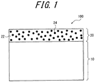
- a protective-coating-coated member 100 comprises: a stainless steel base member 10; and a cermet coating 20 formed on the stainless steel base member.
- the cermet coating 20 is formed by thermal spraying the cermet powder of the present disclosure as the thermal spray material onto the stainless steel base member 10. Consequently, in the cermet coating 20, carbide particles 24 containing tungsten carbide particles and molybdenum carbide particles, and optionally chromium carbide, are dispersed in a matrix 22 made of Ni or a Ni alloy.
- an electroplating-bath-immersed roll according to an embodiment of the present disclosure comprises the protective-coating-coated member 100.
- the protective-coating-coated member and the electroplating-bath-immersed roll thus formed according to the present disclosure can achieve both high wear resistance and high corrosion resistance against a strong acid having a pH of less than 1.
- a roll member comprising a roll shaft portion 30 and a roll body portion 32, both made of stainless steel, is prepared, and a cermet coating 34 is formed only onto the roll body portion by thermal spraying the cermet powder disclosed herein to thereby produce a electroplating-bath-immersed roll 300.
- the protective-coating-coated member of the present disclosure and the method of producing the same, and the electroplating-bath-immersed roll and the method of producing the same were completed based on our discoveries as described below.
- the reactions of formulas (1) and (2) are electrochemically equivalent, and the total amount of electrons (e - ) generated in the anode reaction is equal to the total amount of electrons consumed in the cathode reaction.
- the dissolution reaction proceeds at a portion where the potential increases locally (i.e., anode), while the electrodeposition reaction proceeds at a portion where the potential lowers locally (i.e., cathode).
- the sites where these reactions take place can be regarded as being uniformly distributed in microscopic scales, and the corrosion uniformly proceeds over the entire surface. Consequently, the surface morphology can maintain an initial good state.
- the plating solution is a strong acid with pH ⁇ 1 or the current density of plating is set excessively high, the reaction may proceed as a result of a cathode or anode reaction taking place in a locally fixed site. In such a case, the surface morphology changes greatly as described below, which may damage the plated product.
- the reaction tends to concentrate at the site where deposition is initially generated, causing a metal to grow. Then, the grown metal deposit grows to a certain size, then falls off due to a load of, for example, rubbing against the steel sheet, and the site where the cathode reaction concentrates shifts to another place.
- deposition of a plating metal such as Sn progresses non-uniformly on the surface, and at the same time fragments of the plating metal that fall off may damage the surface of the steel sheet as a product.
- the reaction concentrates as a result of the anode reaction being fixed at a certain site, a particular element (such as Fe in the roll) constituting the site is selectively dissolved at the grain boundary or the like, which may cause the roll surface or the coated layer to partially fall off as fragments. These fragments that have fallen off from the surface may damage the surface of the steel sheet as a product.
- a particular element such as Fe in the roll
- the corrosion potential relatively decreases in a strong acid plating bath with pH ⁇ 1 or when the current density is excessively high, and the microscopic uniformity of the distribution of the anode and the cathode is reduced, adhesion/detachment of the plating metal and partial damage in the roll surface become conspicuous as a result of localized immobilization, and this may be the cause of decrease in the product yield.
- reaction layer on the surface could be easily removed by washing with water and chemical washing, and deposition of metallic Sn on the removed surface was not observed.
- the corrosion potentials at the time when 20 days passed after immersion were compared. As a result, it was found that stainless steel had a potential higher than that of carbon steel by 0.1 V or more, and maintained a potentially noble state.
- carbide cermets are promising as such a material, it is known that good properties cannot be obtained with the ones described in PTLs 1 to 4. However, we determined that these carbide cermets may be able to improve the electrochemical characteristics in a strong acid plating bath by adjusting the components, and engaged in further studies.
- samples were prepared by coating the surface of stainless steel as a base member with more than ten kinds of carbide cermet powders for thermal spraying including commercially available ones by HVOF thermal spraying, and immersion experiments were conducted using a strong acid plating solution with pH ⁇ 1.0.
- the experimental results revealed that Ni or a NiCr-based alloy is superior for the matrix of the cermet, and when the carbide contains Mo carbide rather than WC particles alone, good corrosion resistance can be obtained.
- carbide particles containing tungsten carbide particles and molybdenum carbide particles are dispersed in a matrix made of Ni or a Ni alloy, wherein the cermet coating contains the tungsten carbide particles in an amount of 40 mass% or more, the molybdenum carbide particles in an amount of 10 mass% to 40 mass%, and chromium either as a carbide or a metal or alloy element contained in the matrix, in an amount of 8 mass% or more.
- a matrix containing Ni as a main component good results were obtained with a NiCr-based alloy, a NiCrMo-based alloy, and a NiCoCrAlY-based alloy.
- Specimens were prepared with a carbide cermet coating satisfying the above conditions being formed on stainless steel by HVOF thermal spraying to form a protective coating, and were subjected to constant-current anode/cathode polarization dissolution experiments.
- the experimental results demonstrated that the formation of a reaction layer was not significant and the surface morphology was still better than the stainless steel.
- a potential higher by about 0.1 V than that of the stainless steel was obtained.
- the above results indicate that the uniformity of the distribution of the anode and the cathode formed on the surface of the above-described carbide cermet coating formed by HVOF thermal spraying is achieved at a finer level than that of stainless steel. It was thus found that there is almost no possibility of the steel sheet being damaged by the reaction product. In this way, we discovered that a protective layer having good corrosion resistance can be formed even in a strong acid plating bath, while having excellent wear resistance.
- a high-velocity flame spraying method such as HVOF or HVAF was found to be desirable.
- HVOF or HVAF a high-velocity flame spraying method
- the porosity greatly differs, and in the case of a layer obtained by a thermal spraying method other than the high-velocity flame spraying method such as HVOF or HVAF, it was difficult to maintain a satisfactory surface condition; for example, the solution infiltrated into the layer.
- the carbide when heat treatment is performed on the resulting layer at a high temperature for the purpose of lowering the porosity, the carbide is decarburized into lower carbide or a reaction phase forms with the matrix components, causing a remarkable degradation in wear resistance and corrosion resistance.
- a high-velocity flame spraying method such as HVOF or HVAF is preferable as the method of forming a carbide cermet coating.
- the surface roughness Ra of the carbide cermet coating is preferably 0.5 ⁇ m to 10 ⁇ m.
- Samples were prepared in conformity with conventional roll specifications and roll specifications according to the present disclosure, and subjected to immersion tests for 20 days in a strong-acid plating solution (methanesulfonic acid 50g/L, tin ion concentration 25 g/L) adjusted to pH ⁇ 1.
- a strong-acid plating solution methanesulfonic acid 50g/L, tin ion concentration 25 g/L
- Five samples listed in Table 1 were prepared. Specifically, in Sample No. 1, the base member was a conventional carbon steel and the protective layer was also a conventional sample. On the other hand, in Sample Nos. 2 to 5, the base member was made of stainless steel. Regarding the protective layers, Sample No. 2 adopted a conventional layer as in Sample No. 1, and Sample Nos. 3 to 5 used HVOF layers of various carbide cermets using Ni or a Ni base alloy as the matrix; among these, Sample No.
- the Mo content was 9.4 mass%
- the Cr content was 8.7 mass%
- the WC particle size was 0.1 ⁇ m minimum and 6 ⁇ m maximum
- the particle size of Mo 2 C particles was 0.1 ⁇ m minimum and 6 ⁇ m maximum
- the surface roughness Ra was 3.0 ⁇ m.
- Table 1 lists the results of observation of the surface conditions of the protective layer with the electron microscope after immersion for 20 days, as well as the measurements of the corrosion potential. Table 1 also lists the results of Suga wear tests (#120-SiC paper, load 3.25 kgf, 400 reciprocations) separately performed on the protective layers. The layer observation results were evaluated according to the following criteria:
- Examples 4 to 11 of the present disclosure provided both high wear resistance and high corrosion resistance against a strong acid having a pH of less than 1.
- FIGS. 2A and 2B illustrate a comparison between the structure of a conventional roll and the structure of a roll according to the present disclosure.
- a shaft portion was formed by shrink-fitting a carbon steel tube to a copper shaft core
- a body portion was formed by shrink-fitting a carbon steel sleeve with a protective layer formed thereon by thermal spraying to a roll body portion formed of a carbon steel tube, and these were combined to form a whole roll body.
- FIG. 2B it is only necessary to form a thermal sprayed coating on the roll body made of stainless steel, and it will be readily appreciated that the roll body can be extremely easily fabricated.
- Sample No. 6 in Example 2 was adopted as the layer specification according to the present disclosure.
- Heat generation by energization of each roll was measured with a thermoviewer, and both were determined to be within the range of 0.14 °C/min to 0.16 °C/min, in which operability is not impaired.
- the composition of the plating bath was the same as in Example 1.
- the roll pressing pressure on the steel sheet was 0.2 MPa and the sheet passing speed was in the range of 150 m/min to 490 m/min.
- Each roll was used for 230 days. After completion of use, each roll was pulled up from the bath, and the surface roughness of the sheet passing portion and the amount of Sn adhesion were investigated. The results are presented in Table 3.
- Table 3 Conventional product Our product Ra before use 3.0 ⁇ m 3.0 ⁇ m Ra after use 0.81 ⁇ m 1.08 ⁇ m Tin adhesion to roll surface 5.2 mass% 4.7 mass% Failure rate 2.37 % 0.43 %
- the failure rate of the product was successfully lowered to 0.43 %, which is 1/5 or less, in the case of using rolls of the present disclosure, while it was as high as 2.37 % in the case of using conventional rolls.
- the reason is considered to be that due to the improvement of corrosion resistance, the damage in the layer which would be the cause of defect and the occurrence rate of coarsen fragments of the electrodeposited Sn were greatly reduced.
- the use limit of rolls was up to Ra of 0.5 ⁇ m in surface roughness, and that the frequency at which the product suffers scratches increased with a roll having an initial surface roughness Ra exceeding 10 ⁇ m. Therefore, the surface roughness Ra of the cermet coating according to the present disclosure is preferably from 0.5 ⁇ m to 10 ⁇ m.
- the cermet powder of the present disclosure can be suitably used as the material of a protective layer (cermet coating) in a protective-coating-coated member such as an electroplating-bath-immersed roll.
- a protective-coating-coated member such as an electroplating-bath-immersed roll.
- the electroplating-bath-immersed roll of the present disclosure can be suitably used, for example, as a conductor roll or the like even in an electroplating bath of a strong acid having a pH of less than 1.
Landscapes
- Chemical & Material Sciences (AREA)
- Engineering & Computer Science (AREA)
- Organic Chemistry (AREA)
- Materials Engineering (AREA)
- Metallurgy (AREA)
- Chemical Kinetics & Catalysis (AREA)
- Mechanical Engineering (AREA)
- Physics & Mathematics (AREA)
- Plasma & Fusion (AREA)
- Electrochemistry (AREA)
- Electroplating Methods And Accessories (AREA)
- Coating By Spraying Or Casting (AREA)
- Powder Metallurgy (AREA)
Abstract
Description
- The present disclosure relates to a cermet powder, a protective-coating-coated member and a method of producing the same, and an electroplating-bath-immersed roll and a method of producing the same.
- Conventionally, as a method of producing a conductor roll used in an electroplating bath, the following have been proposed. JPH1198460A (PTL 1) describes a method in which plasma arc spraying is performed on a surface of a carbon steel roll using as a thermal spraying material an alloy containing Co or Ni as a main component and an additive of Cr, C, Fe, Mo, or the like under a low-pressure oxygen-free atmosphere, and the coating is then subjected to a hot melt treatment by plasma arc heating under the same atmosphere to form a nonporous thermal sprayed coating.
- JPH5295592A (PTL 2) describes a method in which a thermal-spray coated layer is formed by thermal spraying a mixed powder composed of a carbide cermet powder and a C-containing nickel chromium alloy powder on the surface of a carbon-steel roll body portion, then causing redeposition of carbide by heating the thermal spray coating layer to form a redeposited-carbide-dispersed thermal sprayed coating, and subsequently shrink-fitting the roll body portion to the outside of the roll base member.
-
JP200288461A -
JP2006183107A -
- PTL 1: JPH1198460A
- PTL 2: JPH5295592A
- PTL 3:
JP200288461A - PTL 4:
JP2006183107A - In PTL 1, a plating solution of a strong acid having a pH of less than 1 has the problem that the plating solution infiltrates from the surface of the coating after continuous use, causing the adhesion between the roll substrate and the thermal sprayed coating to decrease and the coating to peel off from the surface of the substrate. In fact, the technique of PTL 1 is not implemented under severe circumstances such as a pH below 1, in which the implementation conditions are only demonstrated in the current density range as low as 5 A/dm2 to 20 A/dm2, and the operation period is as short as 1,000 hours. This means that the technique of PTL 1 fails to address a long-term operation, such as one month continuous operation. In addition, since the thermal melting treatment of the coating is performed after thermal spraying, there is a problem of increased manufacturing cost.
- Again, in PTL 2, a plating solution of a strong acid having a pH of less than 1 has the problem that the plating solution infiltrates from the surface of the coating after continuous use, causing the adhesion between the roll substrate and the thermal sprayed coating to decrease and the coating to peel off from the surface of the substrate. In addition, the edge of the roll is acid corroded by the plating solution, leading to the problem of fragments lowering the product yield. It is also necessary to carry out remelting treatment on the roll after thermal spraying, causing a problem that the time and cost associated with roll regeneration including shrink-fitting are increased.
- Also in PTL 3, a plating solution of a strong acid having a pH of less than 1 has the problem that the plating solution infiltrates from the surface of the coating after continuous use, causing the adhesion between the roll substrate and the thermal sprayed coating to decrease and the coating to peel off from the surface of the substrate. It is also necessary to carry out remelting treatment on the roll after thermal spraying, causing a problem that the time and cost associated with roll regeneration are increased. In addition, when applying this coating to a stainless steel roll, the remelting treatment causes cracking at the crystal grain boundary due to heating of the stainless steel, and the roll is damaged. For this reason, carbon steel having low corrosion resistance has to be used, leading to the problem of fragments of acid-corroded carbon steel lowering the product yield.
- Also in PTL 4, a plating solution of a strong acid having a pH of less than 1 has the problem that the plating solution infiltrates from the surface of the coating after continuous use, causing the adhesion between the roll substrate and the thermal sprayed coating to decrease and the coating to peel off from the surface of the substrate. Actually, in the test of acid corrosiveness by immersion in a plating solution in PTL 4, the pH is 3.0, and no test was conducted under severe environments such as a pH below 1. It is also necessary to carry out remelting treatment on the roll after thermal spraying, causing a problem that the time and cost associated with roll regeneration are increased. In addition, when applying this coating to a stainless steel roll, the remelting treatment causes cracking at the crystal grain boundary due to heating of the stainless steel, and the roll is damaged. For this reason, carbon steel having low corrosion resistance has to be used, leading to the problem of fragments of acid-corroded carbon steel lowering the product yield.
- As described above, the conventional conductor rolls are primarily characterized in that carbon steel is used as the roll material, and for the purpose of preventing reaction of the carbon steel with the plating solution, a coated layer of a NiCr-based alloy is formed on the roll surface. This coated layer is characterized by containing a carbide (or cermet) mainly composed of WC for the purpose of preventing wear due to rubbing against a steel sheet. This may greatly reduce reaction and wear in an acidic plating bath of pH ≥ 1, secure the roll life, and reduce the defective rate.
- However, in such a conventional conductor roll, in the strong acid plating bath with pH < 1, the acid corrosion amount of the carbon steel itself greatly increases, and in addition, the corrosion resistance of the coated layer itself containing carbide becomes insufficient, raising the problem of the effect obtained being small for the cost involved in the production of the roll. That is, it is difficult to achieve both high wear resistance and high corrosion resistance against a strong acid having a pH of less than 1 in those rolls obtained by the conventional technique and conventional surface treatment.
- Further, it was found that in a conventional product having a thermal sprayed coating on the carbon steel roll base member, the thermal sprayed coating and the carbon steel roll base member are damaged due to acid corrosion, and some fragments jump into the plating product, resulting in defects such as pressing flaw and thus lower product yield. In addition, in a general tin electroplating process, it is known that tin ions in the plating solution change to metallic tin, which may cause an electrodeposition on the roll surface. This electrodeposited metallic tin also causes defective products such as pressing flaw, and such tendency becomes remarkable when the above-described conventional roll is used.
- It would thus be helpful to provide a cermet powder that enables preparation of a cermet coating having both high wear resistance and high corrosion resistance against a strong acid having a pH of less than 1. It would also be helpful to provide a protective-coating-coated member and an electroplating-bath-immersed roll that are compatible with high wear resistance and high corrosion resistance against a strong acid having a pH of less than 1, as well as their production methods.
- We thus provide:
- (1) A cermet powder containing: tungsten carbide particles in an amount of 40 mass% or more; molybdenum carbide particles in an amount of 10 mass% to 40 mass%; and Ni or a Ni alloy as a matrix metal, wherein the cermet powder further contains chromium, either as a carbide or a metal or alloy element contained in the matrix metal, in an amount of 8 mass% or more.
- (2) The cermet powder according to (1) above, wherein the tungsten carbide particles have a content of 70 mass% or less.
- (3) The cermet powder according to (1) or (2) above, wherein the tungsten carbide particles have a particle size distribution within a range of 0.1 µm to 6 µm.
- (4) The cermet powder according to any one of (1) to (3) above, wherein the molybdenum carbide particles have a particle size distribution within a range of 0.1 µm to 6 µm.
- (5) A protective-coating-coated member comprising: a stainless steel base member; and a cermet coating formed on the stainless steel base member, wherein the cermet coating comprises a matrix made of Ni or a Ni alloy, in which tungsten carbide particles and molybdenum carbide particles are dispersed, and, the cermet coating contains the tungsten carbide particles in an amount of 40 mass% or more, the molybdenum carbide particles in an amount of 10 mass% to 40 mass%, and chromium, either as a carbide or a metal or alloy element contained in the matrix, in an amount of 8 mass% or more.
- (6) The protective-coating-coated member according to (5) above, wherein the tungsten carbide particles have a content of 70 mass% or less.
- (7) The protective-coating-coated member according to (5) or (6) above, wherein the tungsten carbide particles in the cermet coating have a particle size distribution within a range of 0.1 µm to 6 µm.
- (8) The protective-coating-coated member according to any one of (5) to (7) above, wherein the molybdenum carbide particles in the cermet coating have a particle size distribution within a range of 0.1 µm to 6 µm.
- (9) The protective-coating-coated member according to any one of (5) to (8) above, wherein the cermet coating has a surface roughness Ra of 0.5 µm to 10 µm.
- (10) A method of producing a protective-coating-coated member, comprising thermal spraying the cermet powder as recited in any one of (1) to (4) above onto a stainless steel base member.
- (11) The method of producing a protective-coating-coated member according to (10) above, wherein the thermal spraying is HVOF thermal spraying.
- (12) An electroplating-bath-immersed roll comprising the protective-coating-coated member as recited in any one of (5) to (9) above.
- (13) An electroplating-bath-immersed roll comprising a roll shaft portion and a roll body portion, both made of stainless steel, wherein only the roll body portion comprises the protective-coating-coated member as recited in any one of (5) to (9) above.
- (14) A method of producing an electroplating-bath-immersed roll, the method comprising: preparing a roll member comprising a roll shaft portion and a roll body portion, both made of stainless steel; and forming a cermet coating only onto the roll body portion by thermal spraying the cermet powder as recited in any one of (1) to (4) above.
- (15) The method of producing an electroplating-bath-immersed roll according to (14) above, wherein the thermal spraying is HVOF thermal spraying.
- With the cermet powder of the present disclosure, it is possible to prepare a cermet coating that offers both high wear resistance and high corrosion resistance against a strong acid having a pH of less than 1.
Further, the protective-coating-coated member and the electroplating-bath-immersed roll of the present disclosure can achieve both high wear resistance and high corrosion resistance against a strong acid having a pH of less than 1. - In the accompanying drawings:
-
FIG. 1 is a schematic cross-sectional view of a protective-coating-coatedmember 100 according to one of the embodiments of the present disclosure; and -
FIG. 2A is a schematic cross-sectional view of a conventional electroplating-bath-immersed roll 200, whileFIG. 2B is a schematic cross-sectional view of an electroplating-bath-immersedroll 300 according to one of the embodiments of the present disclosure. - A cermet powder according to one of the embodiments of the present disclosure contains: tungsten carbide particles in an amount of 40 mass% or more; molybdenum carbide particles in an amount of 10 mass% to 40 mass%; Ni or a Ni alloy as a matrix metal; and chromium either as a carbide or a metal or alloy element in the matrix, in an amount of 8 mass% or more. With this cermet powder, it is possible to produce a cermet coating that offers both high wear resistance and high corrosion resistance against a strong acid having a pH of less than 1. Each component of the cermet powder of the present disclosure will be described below.
- The tungsten carbide particles serve to impart high wear resistance and relatively high corrosion resistance to the cermet coating. The tungsten carbide particles include for example WC particles. The content of the tungsten carbide particles needs to be 40 mass% or more. The reason is that if it is less than 40 mass%, the cermet coating cannot provide sufficient wear resistance. Also, the content of the tungsten carbide particles is preferably 70 mass% or less. The reason is that if it exceeds 70 mass%, the content of the other components becomes so small that the cermet coating cannot provide high corrosion resistance against a strong acid having a pH of less than 1. From the viewpoint of reliably achieving the effect of the present disclosure, the tungsten carbide particles preferably have a particle size distribution within a range of 0.1 µm to 6 µm.
- The molybdenum carbide particles are important components in the present disclosure, which plays a role of imparting to the cermet coating not only high wear resistance but also high corrosion resistance to a strong acid having a pH of less than 1. The molybdenum carbide particles include for example Mo2C particles. The content of the molybdenum carbide particles needs to be 10 mass% to 40 mass%. The reason is that if the content is less than 10 mass%, the cermet coating cannot provide high corrosion resistance against a strong acid having a pH of less than 1, and if it exceeds 40 mass%, the content of the other components, in particular, tungsten carbide particles, must be reduced, resulting in insufficient wear resistance of the cermet coating. From the viewpoint of reliably achieving the effect of the present disclosure, the molybdenum carbide particles preferably have a particle size distribution within a range of of 0.1 µm to 6 µm.
- The cermet powder of the present disclosure contains Ni or a Ni alloy as a matrix metal. Examples of the Ni alloy include a NiCr-based alloy, a NiCrMo-based alloy, and a NiCoCrAlY-based alloy, containing Ni as a main component. Ni as a matrix metal plays a role of imparting to the cermet coating high corrosion resistance to a strong acid having a pH of less than 1. From this viewpoint, the Ni content in the cermet powder is preferably 5 mass% or more. Further, in view of the preferable content of the other components, the Ni content in the cermet powder is preferably 20 mass% or less.
- The cermet powder of the present disclosure contains chromium, either as a carbide or a metal or alloy element contained in the matrix metal, in an amount of 8 mass% or more. This chromium plays a role of imparting to the cermet coating high corrosion resistance to a strong acid having a pH of less than 1, and from that viewpoint its content needs to be 8 mass% or more. In view of the preferable content of the other components, the content of chromium in the cermet powder is preferably 20 mass% or less. In the case where the cermet powder of the present disclosure contains chromium carbide particles (Cr3C2 particles), from the viewpoint of ensuring the effect of the present disclosure, the particle size distribution thereof is preferably within a range of 0.1 µm to 6 µm.
- The cermet powder of the present disclosure preferably consists of the above components and inevitable impurities.
- In the cermet powder of the present disclosure, the molybdenum content is preferably not less than the chromium content from the viewpoint of imparting to the cermet coating high corrosion resistance to a strong acid having a pH of less than 1.
- Regarding the cermet powder of the present disclosure, its production method is not particularly limited, and it can be produced by a known or arbitrary method such as a melt pulverization method, a sintering pulverization method, or a granulation sintering method.
- (Protective-coating-coated Member and Method of Producing the Same, and Electroplating-bath-immersed Roll and Method of Producing the Same)
Referring toFIG. 1 , a protective-coating-coatedmember 100 according to one of the embodiments of the present disclosure comprises: a stainlesssteel base member 10; and acermet coating 20 formed on the stainless steel base member. Thecermet coating 20 is formed by thermal spraying the cermet powder of the present disclosure as the thermal spray material onto the stainlesssteel base member 10. Consequently, in thecermet coating 20,carbide particles 24 containing tungsten carbide particles and molybdenum carbide particles, and optionally chromium carbide, are dispersed in amatrix 22 made of Ni or a Ni alloy. The content and particle size distribution of the tungsten carbide particles, the content and particle size distribution of the molybdenum carbide particles, the Ni content, the chromium content, and the particle size distribution of the chromium carbide particles in thecermet coating 20 are the same as those described above in conjunction with thecermet powder 20. In addition, an electroplating-bath-immersed roll according to an embodiment of the present disclosure comprises the protective-coating-coatedmember 100. The protective-coating-coated member and the electroplating-bath-immersed roll thus formed according to the present disclosure can achieve both high wear resistance and high corrosion resistance against a strong acid having a pH of less than 1. - In particular, in the present embodiment, referring to
FIG. 2B , it is preferable that a roll member comprising aroll shaft portion 30 and a roll body portion 32, both made of stainless steel, is prepared, and acermet coating 34 is formed only onto the roll body portion by thermal spraying the cermet powder disclosed herein to thereby produce a electroplating-bath-immersedroll 300. - According to the present disclosure, the protective-coating-coated member of the present disclosure and the method of producing the same, and the electroplating-bath-immersed roll and the method of producing the same were completed based on our discoveries as described below.
- As mentioned above, using conventional rolls, the life of the rolls and the product yield are greatly reduced in a strong-acid plating bath such as a methanesulfonic acid solution with pH < 1. In order to elucidate this phenomenon and examine countermeasures, our attention was focused on the electrochemical reaction occurring in a roll in the plating solution. First, it was considered that in a conductor roll in a plating bath, unlike ordinary corrosion reaction, a substitution reaction is in progress that is composed of two main reactions, one being a corrosion reaction (anode reaction) in which Fe (or, for example, Ni in the coated layer) becomes ions in the surface and dissolves in the solution, and the other in which Sn ions in the solution undergo electrodeposition (cathode reaction). For example, when the roll component is Fe and the plating component is Sn, these reactions can be expressed as:
- cathode reaction:
Sn2+ + 2e- → Sn (1)
- anode reaction:
Fe → Fe2+ + 2e- (2).
- The reactions of formulas (1) and (2) are electrochemically equivalent, and the total amount of electrons (e-) generated in the anode reaction is equal to the total amount of electrons consumed in the cathode reaction. On the surface of the conductor roll under such an electrochemical reaction environment, the dissolution reaction proceeds at a portion where the potential increases locally (i.e., anode), while the electrodeposition reaction proceeds at a portion where the potential lowers locally (i.e., cathode).
- In the case where the corrosion potential when the roll is immersed in the solution is relatively high, the sites where these reactions take place can be regarded as being uniformly distributed in microscopic scales, and the corrosion uniformly proceeds over the entire surface. Consequently, the surface morphology can maintain an initial good state. However, under such conditions that the plating solution is a strong acid with pH < 1 or the current density of plating is set excessively high, the reaction may proceed as a result of a cathode or anode reaction taking place in a locally fixed site. In such a case, the surface morphology changes greatly as described below, which may damage the plated product.
- First, with respect to the deposition of plating components such as Sn resulting from the cathode reaction, the reaction tends to concentrate at the site where deposition is initially generated, causing a metal to grow. Then, the grown metal deposit grows to a certain size, then falls off due to a load of, for example, rubbing against the steel sheet, and the site where the cathode reaction concentrates shifts to another place. By repeating such a reaction, deposition of a plating metal such as Sn progresses non-uniformly on the surface, and at the same time fragments of the plating metal that fall off may damage the surface of the steel sheet as a product.
- Further, when the reaction concentrates as a result of the anode reaction being fixed at a certain site, a particular element (such as Fe in the roll) constituting the site is selectively dissolved at the grain boundary or the like, which may cause the roll surface or the coated layer to partially fall off as fragments. These fragments that have fallen off from the surface may damage the surface of the steel sheet as a product.
- In other words, in a conventional roll as described above, the corrosion potential relatively decreases in a strong acid plating bath with pH < 1 or when the current density is excessively high, and the microscopic uniformity of the distribution of the anode and the cathode is reduced, adhesion/detachment of the plating metal and partial damage in the roll surface become conspicuous as a result of localized immobilization, and this may be the cause of decrease in the product yield.
- Therefore, in order to secure the roll life and to maintain a high product yield even in a strong acid plating bath with pH < 1 or even when the current density is set high for the purpose of increasing the line speed, it is necessary to find out a material that can prevent as much as possible the phenomenon in which the reaction would concentrate as a result of a cathode or anode reaction taking place in a locally-fixed site as described above, rather than focusing simply on the amount of reaction. Conversely, providing such a material can prevent the progress of local corrosion as described above, guaranteeing the life of the roll and the product yield.
- In view of the above, static immersion tests were conducted on roll materials in a tin plating solution using methanesulfonic acid with pH < 1, where the change of corrosion potential with time was measured and the degree of substitution reaction was evaluated. The test results revealed that when carbon steel was used as the roll material, the amount of reaction was extremely high, metallic Sn was deposited at every part of the surface, and the deposited lump of metallic Sn repeatedly grew and dropped. On the other hand, when stainless steel such as SUS 316L was used as the roll material, the amount of reaction was considerably low and metal Sn deposition was not found clearly, although a thin reaction layer was observed on the surface. In addition, the reaction layer on the surface could be easily removed by washing with water and chemical washing, and deposition of metallic Sn on the removed surface was not observed. The corrosion potentials at the time when 20 days passed after immersion were compared. As a result, it was found that stainless steel had a potential higher than that of carbon steel by 0.1 V or more, and maintained a potentially noble state.
- From these results, we judged that the amount of reaction is small and immobilization of the anode and the cathode on the surface is not likely to occur even in a strong acid solution with pH < 1 as long as the stainless steel has a corrosion potential of about 0.1 V higher than that of carbon steel. However, since the hardness of stainless steel is at most about
HV 200, there is concern that the wear resistance to rubbing against the steel sheet is low. Accordingly, we made further investigations on the material of the coated layer for protecting stainless steel. It is necessary for the material for protecting stainless steel to have high hardness, excellent wear resistance, and good corrosion resistance in a strong acid plating bath. Although carbide cermets are promising as such a material, it is known that good properties cannot be obtained with the ones described in PTLs 1 to 4. However, we determined that these carbide cermets may be able to improve the electrochemical characteristics in a strong acid plating bath by adjusting the components, and engaged in further studies. - Specifically, samples were prepared by coating the surface of stainless steel as a base member with more than ten kinds of carbide cermet powders for thermal spraying including commercially available ones by HVOF thermal spraying, and immersion experiments were conducted using a strong acid plating solution with pH < 1.0. The experimental results revealed that Ni or a NiCr-based alloy is superior for the matrix of the cermet, and when the carbide contains Mo carbide rather than WC particles alone, good corrosion resistance can be obtained. Therefore, as a result of our further investigations, we discovered that in order to obtain high corrosion resistance in a strong acid solution, it is desirable that Cr be contained as carbide or an alloy element in the matrix in an amount of 8 mass% or more and the content of Mo contained as carbide be at least equal to or more than the content of Cr. It was also found that Mo2C is preferable as the Mo carbide, and that if the content of Mo contained in the cermet is larger than the content of Cr, corrosion resistance will not be impaired, but conversely if the content of Mo is not more than half of the content of Cr, it is difficult to obtain a desired corrosion resistance.
- That is, in a carbide cermet coating for protecting stainless steel from the substitution reaction as described above in a strong acid solution with pH < 1 and for ensuring sufficient wear resistance against sliding operation with a steel sheet, it is desirable that carbide particles containing tungsten carbide particles and molybdenum carbide particles are dispersed in a matrix made of Ni or a Ni alloy, wherein the cermet coating contains the tungsten carbide particles in an amount of 40 mass% or more, the molybdenum carbide particles in an amount of 10 mass% to 40 mass%, and chromium either as a carbide or a metal or alloy element contained in the matrix, in an amount of 8 mass% or more. As a matrix containing Ni as a main component, good results were obtained with a NiCr-based alloy, a NiCrMo-based alloy, and a NiCoCrAlY-based alloy.
- Specimens were prepared with a carbide cermet coating satisfying the above conditions being formed on stainless steel by HVOF thermal spraying to form a protective coating, and were subjected to constant-current anode/cathode polarization dissolution experiments. The experimental results demonstrated that the formation of a reaction layer was not significant and the surface morphology was still better than the stainless steel. In addition, as a result of measuring the corrosion potential, a potential higher by about 0.1 V than that of the stainless steel was obtained. The above results indicate that the uniformity of the distribution of the anode and the cathode formed on the surface of the above-described carbide cermet coating formed by HVOF thermal spraying is achieved at a finer level than that of stainless steel. It was thus found that there is almost no possibility of the steel sheet being damaged by the reaction product. In this way, we discovered that a protective layer having good corrosion resistance can be formed even in a strong acid plating bath, while having excellent wear resistance.
- Here, it was determined that it is important to adjust the particle size of the tungsten carbide particles and the molybdenum carbide particles, which are the main components of the cermet, for achieving both wear resistance and corrosion resistance in a trade-off relationship. Specifically, it was found that when carbides, which are the main component of the cermet, having particle sizes of less than 0.1 µm are used, the wear resistance is remarkably deteriorated, and when particles having a particle size of 6 µm or more are used, the uniformity of the distribution of the anode and the cathode in the solution cannot be maintained sufficiently in microscopic scales. It was determined that when the particle size of the tungsten carbide particles and the molybdenum carbide particles is in the range of 0.1 µm to 6 µm, both wear resistance and corrosion resistance can be compatible.
- As a method of forming a protective layer, a high-velocity flame spraying method such as HVOF or HVAF was found to be desirable. For example, when comparing the cermet coating obtained by a high-velocity flame spraying method such as HVOF or HVAF with the cermet coating by plasma spraying or other thermal spraying method, the porosity greatly differs, and in the case of a layer obtained by a thermal spraying method other than the high-velocity flame spraying method such as HVOF or HVAF, it was difficult to maintain a satisfactory surface condition; for example, the solution infiltrated into the layer. Also, when heat treatment is performed on the resulting layer at a high temperature for the purpose of lowering the porosity, the carbide is decarburized into lower carbide or a reaction phase forms with the matrix components, causing a remarkable degradation in wear resistance and corrosion resistance. Such a tendency was also seen in the layers formed by weld overlaying and cladding method. That is, a high-velocity flame spraying method such as HVOF or HVAF is preferable as the method of forming a carbide cermet coating.
- It was found that even with a protective layer formed by a high-velocity flame spraying method such as HVOF or HVAF, the probability of scratching the steel sheet with protrusions of carbide increases when the surface roughness Ra exceeds 10 µm, and when Ra is less than 0.5 µm, the frictional force is not sufficient and the roll idly rotates on the steel sheet, resulting in impairment of the surface condition of the steel sheet. Therefore, the surface roughness Ra of the carbide cermet coating is preferably 0.5 µm to 10 µm.
- Samples were prepared in conformity with conventional roll specifications and roll specifications according to the present disclosure, and subjected to immersion tests for 20 days in a strong-acid plating solution (methanesulfonic acid 50g/L, tin ion concentration 25 g/L) adjusted to pH < 1. Five samples listed in Table 1 were prepared. Specifically, in Sample No. 1, the base member was a conventional carbon steel and the protective layer was also a conventional sample. On the other hand, in Sample Nos. 2 to 5, the base member was made of stainless steel. Regarding the protective layers, Sample No. 2 adopted a conventional layer as in Sample No. 1, and Sample Nos. 3 to 5 used HVOF layers of various carbide cermets using Ni or a Ni base alloy as the matrix; among these, Sample No. 5 corresponds to the cermet specification of our example of the present disclosure. In the layer of Sample No. 5, the Mo content was 9.4 mass%, the Cr content was 8.7 mass%, the WC particle size was 0.1 µm minimum and 6 µm maximum, the particle size of Mo2C particles was 0.1 µm minimum and 6 µm maximum, and the surface roughness Ra was 3.0 µm. Each sample was prepared such that the exposed portion of the base member and the protective layer portion had substantially the same surface area and devised such that the properties of the boundary portion between the layer and the base member could be evaluated.
- To evaluate the corrosion resistance of the protective layer, the change in mass (weight loss due to corrosion) before and after immersion was measured for each sample, and the results are presented in Table 1. In addition to the change in mass, Table 1 lists the results of observation of the surface conditions of the protective layer with the electron microscope after immersion for 20 days, as well as the measurements of the corrosion potential. Table 1 also lists the results of Suga wear tests (#120-SiC paper, load 3.25 kgf, 400 reciprocations) separately performed on the protective layers. The layer observation results were evaluated according to the following criteria:
- Excellent:
- almost no change
- Good:
- slightly changed
- Fair:
- changed
- Poor:
- significantly changed
- As is clear from the results in Table 1, in the plating solution with pH < 1, the change in mass was significant in Sample Nos. 1 to 4 in accordance with the conventional specifications, particularly in Sample No. 1 using carbon steel as the base member, leading to deterioration in the surface morphology. Furthermore, in the specimens in accordance with the conventional specification using carbon steel as the base member, the boundary between the layer and the base member was markedly broken by corrosion. In contrast, it can be seen that not only the change in mass was small but also the surface morphology was difficult to deteriorate in those samples in which stainless steel was protected with a cermet coating. In particular, in Sample No. 5 which is an example of the present disclosure, the surface morphology was much better than the other samples. This also corresponds to the measurement result of the corrosion potential (the highest in the measurement sample), demonstrating that the uniformity of the distribution of the anode and the cathode on the surface of the coating was excellent. In addition, it can be seen that our examples were excellent also from the viewpoint of wear resistance.
- Focusing on the mix proportion of the protective layer of Sample No. 5 in Example 1, various cermet powders containing Ni or a Ni-20Cr alloy as a matrix, as well as WC particles, Cr3C2 particles, and Mo2C particles with the adjusted particle size distribution within a range of 0.1 µm to 6 µm, were prepared. Each obtained cermet powder was HVOF thermal sprayed onto a stainless steel to form a protective layer. The composition of the layer in each sample is presented in Table 2. Immersion tests were conducted in the same way as in Example 1, and Suga wear tests were carried out. The evaluation results are presented in Table 2.
Table 2 Sample No. Chemical composition of coating (mass%) Evaluation results Category Immersion test Wear test WC Cr3C2 Mo2C Ni Ni-20Cr Mo content Cr content Coating observation results Change in mass (g) Amount of wear (mg) 1 73 20 0 7 0 0 17.3 Fair 0.33 0.5 Comparative Example 2 75 10 0 15 0 0 8.7 Fair 0.35 0.7 Comparative Example 3 75 10 0 0 15 0 11.7 Fair 0.34 0.7 Comparative Example 4 70 10 10 10 0 9.4 8.7 Good 0.26 0.5 Example 5 70 10 10 0 10 9.4 10.7 Good 0.26 0.5 Example 6 60 10 20 10 0 18.8 8.7 Good 0.25 0.7 Example 7 60 10 20 0 10 18.8 10.7 Good 0.25 0.7 Example 8 50 10 30 10 0 28.2 8.7 Excellent 0.24 0.9 Example 9 50 10 30 0 10 28.2 10.7 Excellent 0.24 0.9 Example 10 50 20 20 10 0 18.8 17.3 Excellent 0.25 1.0 Example 11 40 10 40 10 0 37.6 8.7 Excellent 0.24 1.0 Example 12 30 20 30 20 0 28.2 17.3 Excellent 0.24 1.2 Comparative Example 13 30 20 30 0 20 28.2 21.3 Excellent 0.24 1.2 Comparative Example 14 20 20 50 0 10 47.1 19.3 Excellent 0.23 1.3 Comparative Example 15 10 10 70 10 0 65.9 8.7 Excellent 0.23 1.3 Comparative Example - As is apparent from the results in Table 2, it is effective to incorporate more Mo2C particles if it is intended to improve the corrosion resistance to the plating solution, and it is effective to incorporate more WC particles for improving the wear resistance. It is found that Examples 4 to 11 of the present disclosure provided both high wear resistance and high corrosion resistance against a strong acid having a pH of less than 1.
- In each sample in which the cermet powder described in Example 2 was formed into a protective layer by atmospheric plasma spraying method, the porosity was high and the adverse effect such as the deterioration of the carbide was large, and as regards the corrosion resistance and the wear resistance, it was not as good as the layer produced by HVOF thermal spraying.
- A comparison is made between a conventional product and a product according to the present disclosure when applied to a conductor roll in an electroplating line.
FIGS. 2A and 2B illustrate a comparison between the structure of a conventional roll and the structure of a roll according to the present disclosure. In the conventional roll inFIG. 2A , a shaft portion was formed by shrink-fitting a carbon steel tube to a copper shaft core, and a body portion was formed by shrink-fitting a carbon steel sleeve with a protective layer formed thereon by thermal spraying to a roll body portion formed of a carbon steel tube, and these were combined to form a whole roll body. In contrast, in the present disclosure, as illustrated inFIG. 2B , it is only necessary to form a thermal sprayed coating on the roll body made of stainless steel, and it will be readily appreciated that the roll body can be extremely easily fabricated. Sample No. 6 in Example 2 was adopted as the layer specification according to the present disclosure. - Heat generation by energization of each roll was measured with a thermoviewer, and both were determined to be within the range of 0.14 °C/min to 0.16 °C/min, in which operability is not impaired. The composition of the plating bath was the same as in Example 1. The roll pressing pressure on the steel sheet was 0.2 MPa and the sheet passing speed was in the range of 150 m/min to 490 m/min. Each roll was used for 230 days. After completion of use, each roll was pulled up from the bath, and the surface roughness of the sheet passing portion and the amount of Sn adhesion were investigated. The results are presented in Table 3.
Table 3 Conventional product Our product Ra before use 3.0 µm 3.0 µm Ra after use 0.81 µm 1.08 µm Tin adhesion to roll surface 5.2 mass% 4.7 mass% Failure rate 2.37 % 0.43 % - The results in Table 3 demonstrated that the surface roughness of the sheet passing portion of each conventional roll decreased from Ra of 3.0 µm before use to Ra of 0.81 µm, which is nearly 1/4, whereas in each roll to which the present disclosure was applied Ra of 1.0 µm or more was maintained after use, and improvement of the layer life of 30 % or more was achieved compared to the conventional ones. It can also be seen that the amount of Sn adhesion was reduced by about 10 % in each roll of the present disclosure as compared with the conventional ones. Both of these results indicate that the corrosion resistance to the plating solution and the wear resistance against the steel sheet can be improved in accordance with the specifications of the present disclosure. In fact, the failure rate of the product was successfully lowered to 0.43 %, which is 1/5 or less, in the case of using rolls of the present disclosure, while it was as high as 2.37 % in the case of using conventional rolls. The reason is considered to be that due to the improvement of corrosion resistance, the damage in the layer which would be the cause of defect and the occurrence rate of coarsen fragments of the electrodeposited Sn were greatly reduced.
- From the results of the same actual operation, it is also found that the use limit of rolls was up to Ra of 0.5 µm in surface roughness, and that the frequency at which the product suffers scratches increased with a roll having an initial surface roughness Ra exceeding 10 µm. Therefore, the surface roughness Ra of the cermet coating according to the present disclosure is preferably from 0.5 µm to 10 µm.
- The cermet powder of the present disclosure can be suitably used as the material of a protective layer (cermet coating) in a protective-coating-coated member such as an electroplating-bath-immersed roll. The electroplating-bath-immersed roll of the present disclosure can be suitably used, for example, as a conductor roll or the like even in an electroplating bath of a strong acid having a pH of less than 1.
-
- 100
- protective-coating-coated member
- 10
- base member (stainless steel)
- 20
- cermet coating
- 22
- matrix
- 24
- carbide particles (WC particles, Mo2C particles, and optionally Cr3C2 particles)
- 300
- electroplating-bath-immersed roll
- 30
- roll shaft portion
- 32
- roll body portion
- 34
- cermet coating (thermal sprayed coating)
| Sample No. | Base Member | Coating components | Coating observation results | Corrosion potential (V vs. Ag/AgCl) | Change in mass (g) | Amount of wear (mg) | Category |
| No.1 | SS400 | 46Ni - 11Cr - 2.5B - 2.5Si - 2.5Fe - 35WC | Poor | -0.7 | >0.46 | 2 | Comparative Example |
| No.2 | SUS316L | 46Ni - 11Cr - 2.5B - 2.5Si - 2.5Fe - 35WC | Poor | -0.6 | 0.35 | 2 | Comparative Example |
| No.3 | SUS316L | WC - 20Cr3C2 - 7Ni | Fair | -0.6 | 0.33 | 0.5 | Comparative Example |
| No.4 | SUS316L | Cr3C2 - 60CoNiCrAlY | Fair | -0.5 | 0.34 | 1.5 | Comparative Example |
| No.5 | SUS316L | WC - 10Mo2C - 10Cr3C2 - 10Ni | Excellent | -0.4 | 0.26 | 0.5 | Example |
Claims (15)
- A cermet powder containing:tungsten carbide particles in an amount of 40 mass% or more;molybdenum carbide particles in an amount of 10 mass% to 40 mass%; andNi or a Ni alloy as a matrix metal, whereinthe cermet powder further contains chromium, either as a carbide or a metal or alloy element contained in the matrix metal, in an amount of 8 mass% or more.
- The cermet powder according to claim 1, wherein the tungsten carbide particles have a content of 70 mass% or less.
- The cermet powder according to claim 1 or 2, wherein the tungsten carbide particles have a particle size distribution within a range of 0.1 µm to 6 µm.
- The cermet powder according to any one of claims 1 to 3, wherein the molybdenum carbide particles have a particle size distribution within a range of 0.1 µm to 6 µm.
- A protective-coating-coated member comprising:a stainless steel base member; anda cermet coating formed on the stainless steel base member, whereinthe cermet coating comprises a matrix made of Ni or a Ni alloy, in which tungsten carbide particles and molybdenum carbide particles are dispersed, andthe cermet coating contains the tungsten carbide particles in an amount of 40 mass% or more, the molybdenum carbide particles in an amount of 10 mass% to 40 mass%, and chromium, either as a carbide or a metal or alloy element contained in the matrix, in an amount of 8 mass% or more.
- The protective-coating-coated member according to claim 5, wherein the tungsten carbide particles have a content of 70 mass% or less.
- The protective-coating-coated member according to claim 5 or 6, wherein the tungsten carbide particles in the cermet coating have a particle size distribution within a range of 0.1 µm to 6 µm.
- The protective-coating-coated member according to any one of claims 5 to 7, wherein the molybdenum carbide particles in the cermet coating have a particle size distribution within a range of 0.1 µm to 6 µm.
- The protective-coating-coated member according to any one of claims 5 to 8, wherein the cermet coating has a surface roughness Ra of 0.5 µm to 10 µm.
- A method of producing a protective-coating-coated member, comprising thermal spraying the cermet powder as recited in any one of claims 1 to 4 onto a stainless steel base member.
- The method of producing a protective-coating-coated member according to claim 10, wherein the thermal spraying is HVOF thermal spraying.
- An electroplating-bath-immersed roll comprising the protective-coating-coated member as recited in any one of claims 5 to 9.
- An electroplating-bath-immersed roll comprising a roll shaft portion and a roll body portion, both made of stainless steel, wherein
only the roll body portion comprises the protective-coating-coated member as recited in any one of claims 5 to 9. - A method of producing an electroplating-bath-immersed roll, the method comprising:preparing a roll member comprising a roll shaft portion and a roll body portion, both made of stainless steel; andforming a cermet coating only onto the roll body portion by thermal spraying the cermet powder as recited in any one of claims 1 to 4.
- The method of producing an electroplating-bath-immersed roll according to claim 14, wherein the thermal spraying is HVOF thermal spraying.
Applications Claiming Priority (2)
| Application Number | Priority Date | Filing Date | Title |
|---|---|---|---|
| JP2016030368 | 2016-02-19 | ||
| PCT/JP2017/005385 WO2017141925A1 (en) | 2016-02-19 | 2017-02-14 | Cermet powder, protective film-coated member and method for producing same, and electroplating-bath roll and method for producing same |
Publications (3)
| Publication Number | Publication Date |
|---|---|
| EP3418421A4 EP3418421A4 (en) | 2018-12-26 |
| EP3418421A1 true EP3418421A1 (en) | 2018-12-26 |
| EP3418421B1 EP3418421B1 (en) | 2021-05-26 |
Family
ID=59625070
Family Applications (1)
| Application Number | Title | Priority Date | Filing Date |
|---|---|---|---|
| EP17753182.9A Active EP3418421B1 (en) | 2016-02-19 | 2017-02-14 | Cermet powder, protective film-coated member and method for producing same |
Country Status (9)
| Country | Link |
|---|---|
| US (1) | US20190032239A1 (en) |
| EP (1) | EP3418421B1 (en) |
| JP (1) | JP6232524B1 (en) |
| KR (1) | KR102177464B1 (en) |
| CN (1) | CN108699667B (en) |
| CO (1) | CO2018009602A2 (en) |
| MY (1) | MY186906A (en) |
| TW (1) | TWI623624B (en) |
| WO (1) | WO2017141925A1 (en) |
Families Citing this family (6)
| Publication number | Priority date | Publication date | Assignee | Title |
|---|---|---|---|---|
| EP3748025A4 (en) * | 2018-01-31 | 2021-10-27 | Hitachi Metals, Ltd. | CEMENTED CARBIDE AND CEMENTED CARBIDE COMPOSITE ROLLER FOR LAMINATION |
| CN109536871A (en) * | 2018-11-27 | 2019-03-29 | 广东省新材料研究所 | The manufacturing method of delivery roll in lithium battery pole slice production |
| CN110724983B (en) * | 2019-10-12 | 2022-02-08 | 天津大学 | Method for preparing nano-copper-coated tungsten carbide core-shell structure powder by pulse electrodeposition |
| WO2021087133A1 (en) * | 2019-11-01 | 2021-05-06 | Exxonmobil Chemical Patents Inc. | Bimetallic materials comprising cermets with improved metal dusting corrosion and abrasion/erosion resistance |
| CN113476863B (en) * | 2021-07-30 | 2024-12-17 | 诸暨市共创游乐设施工程有限公司 | Recreation tubular slideway vehicle conveying system |
| CN117105673B (en) * | 2023-10-24 | 2023-12-29 | 内蒙古工业大学 | Aluminum nitride composite phase ceramic and preparation method thereof |
Family Cites Families (18)
| Publication number | Priority date | Publication date | Assignee | Title |
|---|---|---|---|---|
| US4519840A (en) * | 1983-10-28 | 1985-05-28 | Union Carbide Corporation | High strength, wear and corrosion resistant coatings |
| JP2728254B2 (en) | 1988-02-03 | 1998-03-18 | トーカロ株式会社 | Method of manufacturing conductor roll |
| JP2661837B2 (en) | 1992-04-22 | 1997-10-08 | 川崎製鉄株式会社 | Conductor roll for electroplating and method for manufacturing the same |
| JP3430498B2 (en) * | 1995-05-12 | 2003-07-28 | 住友金属鉱山株式会社 | Corrosion- and wear-resistant self-fluxing alloy material for thermal spraying |
| JPH11131172A (en) * | 1997-08-26 | 1999-05-18 | Topy Ind Ltd | Wear resistant alloy |
| JP2002088461A (en) * | 2000-09-14 | 2002-03-27 | Kawasaki Steel Corp | Corrosion resistant roll |
| KR100762027B1 (en) | 2001-05-17 | 2007-09-28 | 비오이 하이디스 테크놀로지 주식회사 | Etching method of electrode having molybdenum / aluminum / molybdenum 3-layer film structure |
| US7556668B2 (en) * | 2001-12-05 | 2009-07-07 | Baker Hughes Incorporated | Consolidated hard materials, methods of manufacture, and applications |
| JP4561359B2 (en) * | 2004-12-28 | 2010-10-13 | Jfeスチール株式会社 | Conductor roll |
| US8524375B2 (en) * | 2006-05-12 | 2013-09-03 | Praxair S.T. Technology, Inc. | Thermal spray coated work rolls for use in metal and metal alloy sheet manufacture |
| CN101443472A (en) * | 2006-05-12 | 2009-05-27 | 普莱克斯S.T.技术有限公司 | Thermally sprayed work rolls |
| KR101398270B1 (en) * | 2007-11-06 | 2014-05-22 | 아사히 가라스 가부시키가이샤 | Roller for conveying float plate glass, process for producing the same, and process for producing float plate glass with the same |
| WO2011118576A1 (en) * | 2010-03-23 | 2011-09-29 | 旭硝子株式会社 | Sprayed coating of jig for producing glass sheet, and jig for producing glass sheet |
| DE102011112435B3 (en) * | 2011-09-06 | 2012-10-25 | H.C. Starck Gmbh | Cermet powder, process for producing a cermet powder, use of the cermet powder, process for producing a coated part, coated part |
| JP5948216B2 (en) * | 2011-10-25 | 2016-07-06 | 株式会社Ihi | Piston ring manufacturing method |
| CN102586713A (en) * | 2012-03-11 | 2012-07-18 | 赣州章源钨业新材料有限公司 | Novel WC-Cr3C2-Ni thermal spraying powder and preparation process thereof |
| US9624417B2 (en) * | 2012-10-09 | 2017-04-18 | Sandvik Intellectual Property Ab | Low binder, wear resistant hard metal |
| DE102013201103A1 (en) * | 2013-01-24 | 2014-07-24 | H.C. Starck Gmbh | Thermal spray powder for heavily used sliding systems |
-
2017
- 2017-02-14 JP JP2017529403A patent/JP6232524B1/en active Active
- 2017-02-14 CN CN201780011768.0A patent/CN108699667B/en active Active
- 2017-02-14 EP EP17753182.9A patent/EP3418421B1/en active Active
- 2017-02-14 US US16/077,169 patent/US20190032239A1/en not_active Abandoned
- 2017-02-14 WO PCT/JP2017/005385 patent/WO2017141925A1/en not_active Ceased
- 2017-02-14 KR KR1020187026279A patent/KR102177464B1/en active Active
- 2017-02-14 MY MYPI2018702770A patent/MY186906A/en unknown
- 2017-02-17 TW TW106105245A patent/TWI623624B/en active
-
2018
- 2018-09-13 CO CONC2018/0009602A patent/CO2018009602A2/en unknown
Also Published As
| Publication number | Publication date |
|---|---|
| US20190032239A1 (en) | 2019-01-31 |
| KR20180110110A (en) | 2018-10-08 |
| JPWO2017141925A1 (en) | 2018-02-22 |
| EP3418421A4 (en) | 2018-12-26 |
| JP6232524B1 (en) | 2017-11-15 |
| CN108699667B (en) | 2021-06-15 |
| KR102177464B1 (en) | 2020-11-11 |
| TWI623624B (en) | 2018-05-11 |
| TW201734223A (en) | 2017-10-01 |
| CO2018009602A2 (en) | 2018-09-28 |
| EP3418421B1 (en) | 2021-05-26 |
| WO2017141925A1 (en) | 2017-08-24 |
| CN108699667A (en) | 2018-10-23 |
| MY186906A (en) | 2021-08-26 |
Similar Documents
| Publication | Publication Date | Title |
|---|---|---|
| EP3418421B1 (en) | Cermet powder, protective film-coated member and method for producing same | |
| US8168056B2 (en) | Electrocomposite coatings for hard chrome replacement | |
| CN101688285A (en) | Material for covering surface of hot dip galvanizing bath member, process for producing the material, and hot dip galvanizing bath member | |
| Ghasemi et al. | Electrodeposition of rhenium-base layer as a diffusion barrier between the NiCoCrAlY coating and a Ni-based superalloy | |
| US5116431A (en) | Immersion member for hot dip galvanizing bath and method for preparing the same | |
| JP2002146588A (en) | Metal plating method | |
| JP5353613B2 (en) | Coated cemented carbide member | |
| JP5217712B2 (en) | Coated cemented carbide member | |
| JPH10110252A (en) | Conductor roll for electroplating and its production | |
| JP2003096553A (en) | Coating member for carbide cermet thermal spraying film having excellent corrosion resistance, and carbide based cermet thermal spray material | |
| JP2661837B2 (en) | Conductor roll for electroplating and method for manufacturing the same | |
| Chen et al. | Enhanced corrosion and wear resistance of HVOF sprayed WC-10Co-4Cr coatings via magnetron sputtered Ni core-shell modification | |
| JP4286427B2 (en) | High strength alloy and metal coated with the high strength alloy | |
| Tuaweri et al. | Electrodeposition of Zinc-Nickel Alloy Coatings: Effect of Deposition Parameters on its Surface Morphology | |
| CN1636073A (en) | Heat treatment method for a cold-rolled strip with an Ni and/or Co surface coating, sheet metal producible by said method and battery can producible by said method | |
| JPH08269787A (en) | Conductor roll for Ni plating with excellent corrosion resistance and wear resistance | |
| Hashimoto et al. | Sn-P alloys for rapid and stable production of tin solution for tin plating | |
| JP3341858B2 (en) | Roll material for electroplating | |
| JP2018040023A (en) | Member for in-bath apparatus | |
| CN119980378A (en) | Acid electroplating method for preparing a platinum coating on the surface of a nickel-based high-temperature alloy | |
| WO2025169804A1 (en) | Member for apparatus to be used in bath | |
| Aole et al. | Synthesis And Characterization Of Nickel-Alumina Dispersion Strengthened Composite By Electrodeposition Method | |
| JPH09278458A (en) | Mold for molding glass and manufacturing method thereof | |
| JP2004107731A (en) | Surface treated doctor blade |
Legal Events
| Date | Code | Title | Description |
|---|---|---|---|
| STAA | Information on the status of an ep patent application or granted ep patent |
Free format text: STATUS: THE INTERNATIONAL PUBLICATION HAS BEEN MADE |
|
| PUAI | Public reference made under article 153(3) epc to a published international application that has entered the european phase |
Free format text: ORIGINAL CODE: 0009012 |
|
| STAA | Information on the status of an ep patent application or granted ep patent |
Free format text: STATUS: REQUEST FOR EXAMINATION WAS MADE |
|
| 17P | Request for examination filed |
Effective date: 20180912 |
|
| A4 | Supplementary search report drawn up and despatched |
Effective date: 20181018 |
|
| AK | Designated contracting states |
Kind code of ref document: A1 Designated state(s): AL AT BE BG CH CY CZ DE DK EE ES FI FR GB GR HR HU IE IS IT LI LT LU LV MC MK MT NL NO PL PT RO RS SE SI SK SM TR |
|
| AX | Request for extension of the european patent |
Extension state: BA ME |
|
| DAV | Request for validation of the european patent (deleted) | ||
| DAX | Request for extension of the european patent (deleted) | ||
| STAA | Information on the status of an ep patent application or granted ep patent |
Free format text: STATUS: EXAMINATION IS IN PROGRESS |
|
| 17Q | First examination report despatched |
Effective date: 20200130 |
|
| GRAP | Despatch of communication of intention to grant a patent |
Free format text: ORIGINAL CODE: EPIDOSNIGR1 |
|
| STAA | Information on the status of an ep patent application or granted ep patent |
Free format text: STATUS: GRANT OF PATENT IS INTENDED |
|
| RIC1 | Information provided on ipc code assigned before grant |
Ipc: C23C 4/06 20160101ALI20200529BHEP Ipc: C23C 4/10 20160101ALI20200529BHEP Ipc: C22C 29/08 20060101ALI20200529BHEP Ipc: C23C 4/067 20160101AFI20200529BHEP Ipc: C25D 7/06 20060101ALI20200529BHEP Ipc: C23C 4/123 20160101ALI20200529BHEP |
|
| INTG | Intention to grant announced |
Effective date: 20200623 |
|
| GRAJ | Information related to disapproval of communication of intention to grant by the applicant or resumption of examination proceedings by the epo deleted |
Free format text: ORIGINAL CODE: EPIDOSDIGR1 |
|
| STAA | Information on the status of an ep patent application or granted ep patent |
Free format text: STATUS: EXAMINATION IS IN PROGRESS |
|
| GRAP | Despatch of communication of intention to grant a patent |
Free format text: ORIGINAL CODE: EPIDOSNIGR1 |
|
| STAA | Information on the status of an ep patent application or granted ep patent |
Free format text: STATUS: GRANT OF PATENT IS INTENDED |
|
| INTC | Intention to grant announced (deleted) | ||
| RIC1 | Information provided on ipc code assigned before grant |
Ipc: C23C 4/06 20160101ALI20200921BHEP Ipc: C22C 29/06 20060101AFI20200921BHEP Ipc: C22C 29/08 20060101ALI20200921BHEP Ipc: B22F 7/08 20060101ALI20200921BHEP Ipc: C23C 4/10 20160101ALI20200921BHEP Ipc: C25D 7/06 20060101ALI20200921BHEP Ipc: C23C 4/123 20160101ALI20200921BHEP Ipc: C23C 4/067 20160101ALI20200921BHEP |
|
| RIC1 | Information provided on ipc code assigned before grant |
Ipc: C23C 4/10 20160101ALI20200928BHEP Ipc: C25D 7/06 20060101ALI20200928BHEP Ipc: B22F 7/08 20060101ALN20200928BHEP Ipc: C22C 29/08 20060101ALI20200928BHEP Ipc: C22C 29/06 20060101AFI20200928BHEP Ipc: C23C 4/06 20160101ALI20200928BHEP Ipc: C23C 4/067 20160101ALI20200928BHEP Ipc: C23C 4/123 20160101ALI20200928BHEP |
|
| INTG | Intention to grant announced |
Effective date: 20201016 |
|
| GRAJ | Information related to disapproval of communication of intention to grant by the applicant or resumption of examination proceedings by the epo deleted |
Free format text: ORIGINAL CODE: EPIDOSDIGR1 |
|
| STAA | Information on the status of an ep patent application or granted ep patent |
Free format text: STATUS: EXAMINATION IS IN PROGRESS |
|
| REG | Reference to a national code |
Ref country code: DE Ref legal event code: R079 Ref document number: 602017039284 Country of ref document: DE Free format text: PREVIOUS MAIN CLASS: C23C0004060000 Ipc: C22C0029060000 |
|
| GRAP | Despatch of communication of intention to grant a patent |
Free format text: ORIGINAL CODE: EPIDOSNIGR1 |
|
| STAA | Information on the status of an ep patent application or granted ep patent |
Free format text: STATUS: GRANT OF PATENT IS INTENDED |
|
| INTC | Intention to grant announced (deleted) | ||
| RIC1 | Information provided on ipc code assigned before grant |
Ipc: C23C 4/067 20160101ALI20201222BHEP Ipc: C25D 7/06 20060101ALI20201222BHEP Ipc: B22F 7/08 20060101ALN20201222BHEP Ipc: C23C 4/10 20160101ALI20201222BHEP Ipc: C23C 4/123 20160101ALI20201222BHEP Ipc: C23C 4/06 20160101ALI20201222BHEP Ipc: C22C 29/06 20060101AFI20201222BHEP Ipc: C22C 29/08 20060101ALI20201222BHEP |
|
| INTG | Intention to grant announced |
Effective date: 20210119 |
|
| GRAS | Grant fee paid |
Free format text: ORIGINAL CODE: EPIDOSNIGR3 |
|
| GRAA | (expected) grant |
Free format text: ORIGINAL CODE: 0009210 |
|
| STAA | Information on the status of an ep patent application or granted ep patent |
Free format text: STATUS: THE PATENT HAS BEEN GRANTED |
|
| AK | Designated contracting states |
Kind code of ref document: B1 Designated state(s): AL AT BE BG CH CY CZ DE DK EE ES FI FR GB GR HR HU IE IS IT LI LT LU LV MC MK MT NL NO PL PT RO RS SE SI SK SM TR |
|
| REG | Reference to a national code |
Ref country code: GB Ref legal event code: FG4D |
|
| REG | Reference to a national code |
Ref country code: CH Ref legal event code: EP |
|
| REG | Reference to a national code |
Ref country code: DE Ref legal event code: R096 Ref document number: 602017039284 Country of ref document: DE |
|
| REG | Reference to a national code |
Ref country code: AT Ref legal event code: REF Ref document number: 1396289 Country of ref document: AT Kind code of ref document: T Effective date: 20210615 |
|
| REG | Reference to a national code |
Ref country code: IE Ref legal event code: FG4D |
|
| REG | Reference to a national code |
Ref country code: LT Ref legal event code: MG9D |
|
| REG | Reference to a national code |
Ref country code: AT Ref legal event code: MK05 Ref document number: 1396289 Country of ref document: AT Kind code of ref document: T Effective date: 20210526 |
|
| PG25 | Lapsed in a contracting state [announced via postgrant information from national office to epo] |
Ref country code: FI Free format text: LAPSE BECAUSE OF FAILURE TO SUBMIT A TRANSLATION OF THE DESCRIPTION OR TO PAY THE FEE WITHIN THE PRESCRIBED TIME-LIMIT Effective date: 20210526 Ref country code: LT Free format text: LAPSE BECAUSE OF FAILURE TO SUBMIT A TRANSLATION OF THE DESCRIPTION OR TO PAY THE FEE WITHIN THE PRESCRIBED TIME-LIMIT Effective date: 20210526 Ref country code: HR Free format text: LAPSE BECAUSE OF FAILURE TO SUBMIT A TRANSLATION OF THE DESCRIPTION OR TO PAY THE FEE WITHIN THE PRESCRIBED TIME-LIMIT Effective date: 20210526 Ref country code: AT Free format text: LAPSE BECAUSE OF FAILURE TO SUBMIT A TRANSLATION OF THE DESCRIPTION OR TO PAY THE FEE WITHIN THE PRESCRIBED TIME-LIMIT Effective date: 20210526 Ref country code: BG Free format text: LAPSE BECAUSE OF FAILURE TO SUBMIT A TRANSLATION OF THE DESCRIPTION OR TO PAY THE FEE WITHIN THE PRESCRIBED TIME-LIMIT Effective date: 20210826 |
|
| REG | Reference to a national code |
Ref country code: NL Ref legal event code: MP Effective date: 20210526 |
|
| PG25 | Lapsed in a contracting state [announced via postgrant information from national office to epo] |
Ref country code: IS Free format text: LAPSE BECAUSE OF FAILURE TO SUBMIT A TRANSLATION OF THE DESCRIPTION OR TO PAY THE FEE WITHIN THE PRESCRIBED TIME-LIMIT Effective date: 20210926 Ref country code: GR Free format text: LAPSE BECAUSE OF FAILURE TO SUBMIT A TRANSLATION OF THE DESCRIPTION OR TO PAY THE FEE WITHIN THE PRESCRIBED TIME-LIMIT Effective date: 20210827 Ref country code: LV Free format text: LAPSE BECAUSE OF FAILURE TO SUBMIT A TRANSLATION OF THE DESCRIPTION OR TO PAY THE FEE WITHIN THE PRESCRIBED TIME-LIMIT Effective date: 20210526 Ref country code: NO Free format text: LAPSE BECAUSE OF FAILURE TO SUBMIT A TRANSLATION OF THE DESCRIPTION OR TO PAY THE FEE WITHIN THE PRESCRIBED TIME-LIMIT Effective date: 20210826 Ref country code: PT Free format text: LAPSE BECAUSE OF FAILURE TO SUBMIT A TRANSLATION OF THE DESCRIPTION OR TO PAY THE FEE WITHIN THE PRESCRIBED TIME-LIMIT Effective date: 20210927 Ref country code: PL Free format text: LAPSE BECAUSE OF FAILURE TO SUBMIT A TRANSLATION OF THE DESCRIPTION OR TO PAY THE FEE WITHIN THE PRESCRIBED TIME-LIMIT Effective date: 20210526 Ref country code: SE Free format text: LAPSE BECAUSE OF FAILURE TO SUBMIT A TRANSLATION OF THE DESCRIPTION OR TO PAY THE FEE WITHIN THE PRESCRIBED TIME-LIMIT Effective date: 20210526 Ref country code: RS Free format text: LAPSE BECAUSE OF FAILURE TO SUBMIT A TRANSLATION OF THE DESCRIPTION OR TO PAY THE FEE WITHIN THE PRESCRIBED TIME-LIMIT Effective date: 20210526 |
|
| PG25 | Lapsed in a contracting state [announced via postgrant information from national office to epo] |
Ref country code: NL Free format text: LAPSE BECAUSE OF FAILURE TO SUBMIT A TRANSLATION OF THE DESCRIPTION OR TO PAY THE FEE WITHIN THE PRESCRIBED TIME-LIMIT Effective date: 20210526 |
|
| PG25 | Lapsed in a contracting state [announced via postgrant information from national office to epo] |
Ref country code: RO Free format text: LAPSE BECAUSE OF FAILURE TO SUBMIT A TRANSLATION OF THE DESCRIPTION OR TO PAY THE FEE WITHIN THE PRESCRIBED TIME-LIMIT Effective date: 20210526 Ref country code: ES Free format text: LAPSE BECAUSE OF FAILURE TO SUBMIT A TRANSLATION OF THE DESCRIPTION OR TO PAY THE FEE WITHIN THE PRESCRIBED TIME-LIMIT Effective date: 20210526 Ref country code: EE Free format text: LAPSE BECAUSE OF FAILURE TO SUBMIT A TRANSLATION OF THE DESCRIPTION OR TO PAY THE FEE WITHIN THE PRESCRIBED TIME-LIMIT Effective date: 20210526 Ref country code: DK Free format text: LAPSE BECAUSE OF FAILURE TO SUBMIT A TRANSLATION OF THE DESCRIPTION OR TO PAY THE FEE WITHIN THE PRESCRIBED TIME-LIMIT Effective date: 20210526 Ref country code: CZ Free format text: LAPSE BECAUSE OF FAILURE TO SUBMIT A TRANSLATION OF THE DESCRIPTION OR TO PAY THE FEE WITHIN THE PRESCRIBED TIME-LIMIT Effective date: 20210526 Ref country code: SK Free format text: LAPSE BECAUSE OF FAILURE TO SUBMIT A TRANSLATION OF THE DESCRIPTION OR TO PAY THE FEE WITHIN THE PRESCRIBED TIME-LIMIT Effective date: 20210526 Ref country code: SM Free format text: LAPSE BECAUSE OF FAILURE TO SUBMIT A TRANSLATION OF THE DESCRIPTION OR TO PAY THE FEE WITHIN THE PRESCRIBED TIME-LIMIT Effective date: 20210526 |
|
| REG | Reference to a national code |
Ref country code: DE Ref legal event code: R097 Ref document number: 602017039284 Country of ref document: DE |
|
| PLBE | No opposition filed within time limit |
Free format text: ORIGINAL CODE: 0009261 |
|
| STAA | Information on the status of an ep patent application or granted ep patent |
Free format text: STATUS: NO OPPOSITION FILED WITHIN TIME LIMIT |
|
| 26N | No opposition filed |
Effective date: 20220301 |
|
| PG25 | Lapsed in a contracting state [announced via postgrant information from national office to epo] |
Ref country code: IS Free format text: LAPSE BECAUSE OF FAILURE TO SUBMIT A TRANSLATION OF THE DESCRIPTION OR TO PAY THE FEE WITHIN THE PRESCRIBED TIME-LIMIT Effective date: 20210926 Ref country code: AL Free format text: LAPSE BECAUSE OF FAILURE TO SUBMIT A TRANSLATION OF THE DESCRIPTION OR TO PAY THE FEE WITHIN THE PRESCRIBED TIME-LIMIT Effective date: 20210526 |
|
| PG25 | Lapsed in a contracting state [announced via postgrant information from national office to epo] |
Ref country code: IT Free format text: LAPSE BECAUSE OF FAILURE TO SUBMIT A TRANSLATION OF THE DESCRIPTION OR TO PAY THE FEE WITHIN THE PRESCRIBED TIME-LIMIT Effective date: 20210526 |
|
| PG25 | Lapsed in a contracting state [announced via postgrant information from national office to epo] |
Ref country code: MC Free format text: LAPSE BECAUSE OF FAILURE TO SUBMIT A TRANSLATION OF THE DESCRIPTION OR TO PAY THE FEE WITHIN THE PRESCRIBED TIME-LIMIT Effective date: 20210526 |
|
| REG | Reference to a national code |
Ref country code: CH Ref legal event code: PL |
|
| REG | Reference to a national code |
Ref country code: BE Ref legal event code: MM Effective date: 20220228 |
|
| GBPC | Gb: european patent ceased through non-payment of renewal fee |
Effective date: 20220214 |
|
| PG25 | Lapsed in a contracting state [announced via postgrant information from national office to epo] |
Ref country code: LU Free format text: LAPSE BECAUSE OF NON-PAYMENT OF DUE FEES Effective date: 20220214 |
|
| PG25 | Lapsed in a contracting state [announced via postgrant information from national office to epo] |
Ref country code: FR Free format text: LAPSE BECAUSE OF NON-PAYMENT OF DUE FEES Effective date: 20220228 |
|
| PG25 | Lapsed in a contracting state [announced via postgrant information from national office to epo] |
Ref country code: LI Free format text: LAPSE BECAUSE OF NON-PAYMENT OF DUE FEES Effective date: 20220228 Ref country code: IE Free format text: LAPSE BECAUSE OF NON-PAYMENT OF DUE FEES Effective date: 20220214 Ref country code: GB Free format text: LAPSE BECAUSE OF NON-PAYMENT OF DUE FEES Effective date: 20220214 Ref country code: CH Free format text: LAPSE BECAUSE OF NON-PAYMENT OF DUE FEES Effective date: 20220228 |
|
| PG25 | Lapsed in a contracting state [announced via postgrant information from national office to epo] |
Ref country code: BE Free format text: LAPSE BECAUSE OF NON-PAYMENT OF DUE FEES Effective date: 20220228 |
|
| PG25 | Lapsed in a contracting state [announced via postgrant information from national office to epo] |
Ref country code: HU Free format text: LAPSE BECAUSE OF FAILURE TO SUBMIT A TRANSLATION OF THE DESCRIPTION OR TO PAY THE FEE WITHIN THE PRESCRIBED TIME-LIMIT; INVALID AB INITIO Effective date: 20170214 |
|
| PG25 | Lapsed in a contracting state [announced via postgrant information from national office to epo] |
Ref country code: MK Free format text: LAPSE BECAUSE OF FAILURE TO SUBMIT A TRANSLATION OF THE DESCRIPTION OR TO PAY THE FEE WITHIN THE PRESCRIBED TIME-LIMIT Effective date: 20210526 Ref country code: CY Free format text: LAPSE BECAUSE OF FAILURE TO SUBMIT A TRANSLATION OF THE DESCRIPTION OR TO PAY THE FEE WITHIN THE PRESCRIBED TIME-LIMIT Effective date: 20210526 |
|
| PG25 | Lapsed in a contracting state [announced via postgrant information from national office to epo] |
Ref country code: MT Free format text: LAPSE BECAUSE OF FAILURE TO SUBMIT A TRANSLATION OF THE DESCRIPTION OR TO PAY THE FEE WITHIN THE PRESCRIBED TIME-LIMIT Effective date: 20210526 |
|
| PG25 | Lapsed in a contracting state [announced via postgrant information from national office to epo] |
Ref country code: TR Free format text: LAPSE BECAUSE OF FAILURE TO SUBMIT A TRANSLATION OF THE DESCRIPTION OR TO PAY THE FEE WITHIN THE PRESCRIBED TIME-LIMIT Effective date: 20210526 |
|
| PGFP | Annual fee paid to national office [announced via postgrant information from national office to epo] |
Ref country code: DE Payment date: 20251230 Year of fee payment: 10 |