EP3418097A1 - Befüllkopf für einen flüssigkeitstank - Google Patents
Befüllkopf für einen flüssigkeitstank Download PDFInfo
- Publication number
- EP3418097A1 EP3418097A1 EP18176932.4A EP18176932A EP3418097A1 EP 3418097 A1 EP3418097 A1 EP 3418097A1 EP 18176932 A EP18176932 A EP 18176932A EP 3418097 A1 EP3418097 A1 EP 3418097A1
- Authority
- EP
- European Patent Office
- Prior art keywords
- housing part
- connecting piece
- housing
- filling head
- opening
- Prior art date
- Legal status (The legal status is an assumption and is not a legal conclusion. Google has not performed a legal analysis and makes no representation as to the accuracy of the status listed.)
- Granted
Links
Images


Classifications
-
- B—PERFORMING OPERATIONS; TRANSPORTING
- B60—VEHICLES IN GENERAL
- B60K—ARRANGEMENT OR MOUNTING OF PROPULSION UNITS OR OF TRANSMISSIONS IN VEHICLES; ARRANGEMENT OR MOUNTING OF PLURAL DIVERSE PRIME-MOVERS IN VEHICLES; AUXILIARY DRIVES FOR VEHICLES; INSTRUMENTATION OR DASHBOARDS FOR VEHICLES; ARRANGEMENTS IN CONNECTION WITH COOLING, AIR INTAKE, GAS EXHAUST OR FUEL SUPPLY OF PROPULSION UNITS IN VEHICLES
- B60K15/00—Arrangement in connection with fuel supply of combustion engines or other fuel consuming energy converters, e.g. fuel cells; Mounting or construction of fuel tanks
- B60K15/03—Fuel tanks
- B60K15/04—Tank inlets
-
- B—PERFORMING OPERATIONS; TRANSPORTING
- B60—VEHICLES IN GENERAL
- B60K—ARRANGEMENT OR MOUNTING OF PROPULSION UNITS OR OF TRANSMISSIONS IN VEHICLES; ARRANGEMENT OR MOUNTING OF PLURAL DIVERSE PRIME-MOVERS IN VEHICLES; AUXILIARY DRIVES FOR VEHICLES; INSTRUMENTATION OR DASHBOARDS FOR VEHICLES; ARRANGEMENTS IN CONNECTION WITH COOLING, AIR INTAKE, GAS EXHAUST OR FUEL SUPPLY OF PROPULSION UNITS IN VEHICLES
- B60K13/00—Arrangement in connection with combustion air intake or gas exhaust of propulsion units
- B60K13/04—Arrangement in connection with combustion air intake or gas exhaust of propulsion units concerning exhaust
-
- B—PERFORMING OPERATIONS; TRANSPORTING
- B60—VEHICLES IN GENERAL
- B60K—ARRANGEMENT OR MOUNTING OF PROPULSION UNITS OR OF TRANSMISSIONS IN VEHICLES; ARRANGEMENT OR MOUNTING OF PLURAL DIVERSE PRIME-MOVERS IN VEHICLES; AUXILIARY DRIVES FOR VEHICLES; INSTRUMENTATION OR DASHBOARDS FOR VEHICLES; ARRANGEMENTS IN CONNECTION WITH COOLING, AIR INTAKE, GAS EXHAUST OR FUEL SUPPLY OF PROPULSION UNITS IN VEHICLES
- B60K15/00—Arrangement in connection with fuel supply of combustion engines or other fuel consuming energy converters, e.g. fuel cells; Mounting or construction of fuel tanks
- B60K15/03—Fuel tanks
- B60K15/035—Fuel tanks characterised by venting means
- B60K2015/03523—Arrangements of the venting tube
- B60K2015/03538—Arrangements of the venting tube the venting tube being connected with the filler tube
-
- B—PERFORMING OPERATIONS; TRANSPORTING
- B60—VEHICLES IN GENERAL
- B60K—ARRANGEMENT OR MOUNTING OF PROPULSION UNITS OR OF TRANSMISSIONS IN VEHICLES; ARRANGEMENT OR MOUNTING OF PLURAL DIVERSE PRIME-MOVERS IN VEHICLES; AUXILIARY DRIVES FOR VEHICLES; INSTRUMENTATION OR DASHBOARDS FOR VEHICLES; ARRANGEMENTS IN CONNECTION WITH COOLING, AIR INTAKE, GAS EXHAUST OR FUEL SUPPLY OF PROPULSION UNITS IN VEHICLES
- B60K15/00—Arrangement in connection with fuel supply of combustion engines or other fuel consuming energy converters, e.g. fuel cells; Mounting or construction of fuel tanks
- B60K15/03—Fuel tanks
- B60K15/035—Fuel tanks characterised by venting means
- B60K2015/03561—Venting means working at specific times
- B60K2015/03576—Venting during filling the reservoir
-
- B—PERFORMING OPERATIONS; TRANSPORTING
- B60—VEHICLES IN GENERAL
- B60K—ARRANGEMENT OR MOUNTING OF PROPULSION UNITS OR OF TRANSMISSIONS IN VEHICLES; ARRANGEMENT OR MOUNTING OF PLURAL DIVERSE PRIME-MOVERS IN VEHICLES; AUXILIARY DRIVES FOR VEHICLES; INSTRUMENTATION OR DASHBOARDS FOR VEHICLES; ARRANGEMENTS IN CONNECTION WITH COOLING, AIR INTAKE, GAS EXHAUST OR FUEL SUPPLY OF PROPULSION UNITS IN VEHICLES
- B60K15/00—Arrangement in connection with fuel supply of combustion engines or other fuel consuming energy converters, e.g. fuel cells; Mounting or construction of fuel tanks
- B60K15/03—Fuel tanks
- B60K15/04—Tank inlets
- B60K2015/0458—Details of the tank inlet
- B60K2015/047—Manufacturing of the fuel inlet or connecting elements to fuel inlet, e.g. pipes or venting tubes
-
- B—PERFORMING OPERATIONS; TRANSPORTING
- B60—VEHICLES IN GENERAL
- B60K—ARRANGEMENT OR MOUNTING OF PROPULSION UNITS OR OF TRANSMISSIONS IN VEHICLES; ARRANGEMENT OR MOUNTING OF PLURAL DIVERSE PRIME-MOVERS IN VEHICLES; AUXILIARY DRIVES FOR VEHICLES; INSTRUMENTATION OR DASHBOARDS FOR VEHICLES; ARRANGEMENTS IN CONNECTION WITH COOLING, AIR INTAKE, GAS EXHAUST OR FUEL SUPPLY OF PROPULSION UNITS IN VEHICLES
- B60K15/00—Arrangement in connection with fuel supply of combustion engines or other fuel consuming energy converters, e.g. fuel cells; Mounting or construction of fuel tanks
- B60K15/03—Fuel tanks
- B60K15/04—Tank inlets
- B60K2015/0458—Details of the tank inlet
- B60K2015/048—Arrangements for sealing the fuel inlet during filling
-
- B—PERFORMING OPERATIONS; TRANSPORTING
- B60—VEHICLES IN GENERAL
- B60Y—INDEXING SCHEME RELATING TO ASPECTS CROSS-CUTTING VEHICLE TECHNOLOGY
- B60Y2410/00—Constructional features of vehicle sub-units
- B60Y2410/13—Materials or fluids with special properties
- B60Y2410/132—Magnetic, e.g. permanent magnets
-
- F—MECHANICAL ENGINEERING; LIGHTING; HEATING; WEAPONS; BLASTING
- F01—MACHINES OR ENGINES IN GENERAL; ENGINE PLANTS IN GENERAL; STEAM ENGINES
- F01N—GAS-FLOW SILENCERS OR EXHAUST APPARATUS FOR MACHINES OR ENGINES IN GENERAL; GAS-FLOW SILENCERS OR EXHAUST APPARATUS FOR INTERNAL-COMBUSTION ENGINES
- F01N2610/00—Adding substances to exhaust gases
- F01N2610/02—Adding substances to exhaust gases the substance being ammonia or urea
-
- F—MECHANICAL ENGINEERING; LIGHTING; HEATING; WEAPONS; BLASTING
- F01—MACHINES OR ENGINES IN GENERAL; ENGINE PLANTS IN GENERAL; STEAM ENGINES
- F01N—GAS-FLOW SILENCERS OR EXHAUST APPARATUS FOR MACHINES OR ENGINES IN GENERAL; GAS-FLOW SILENCERS OR EXHAUST APPARATUS FOR INTERNAL-COMBUSTION ENGINES
- F01N2610/00—Adding substances to exhaust gases
- F01N2610/14—Arrangements for the supply of substances, e.g. conduits
- F01N2610/1406—Storage means for substances, e.g. tanks or reservoirs
-
- F—MECHANICAL ENGINEERING; LIGHTING; HEATING; WEAPONS; BLASTING
- F01—MACHINES OR ENGINES IN GENERAL; ENGINE PLANTS IN GENERAL; STEAM ENGINES
- F01N—GAS-FLOW SILENCERS OR EXHAUST APPARATUS FOR MACHINES OR ENGINES IN GENERAL; GAS-FLOW SILENCERS OR EXHAUST APPARATUS FOR INTERNAL-COMBUSTION ENGINES
- F01N2610/00—Adding substances to exhaust gases
- F01N2610/14—Arrangements for the supply of substances, e.g. conduits
- F01N2610/1406—Storage means for substances, e.g. tanks or reservoirs
- F01N2610/1413—Inlet and filling arrangements therefore
-
- F—MECHANICAL ENGINEERING; LIGHTING; HEATING; WEAPONS; BLASTING
- F01—MACHINES OR ENGINES IN GENERAL; ENGINE PLANTS IN GENERAL; STEAM ENGINES
- F01N—GAS-FLOW SILENCERS OR EXHAUST APPARATUS FOR MACHINES OR ENGINES IN GENERAL; GAS-FLOW SILENCERS OR EXHAUST APPARATUS FOR INTERNAL-COMBUSTION ENGINES
- F01N3/00—Exhaust or silencing apparatus having means for purifying, rendering innocuous, or otherwise treating exhaust
- F01N3/08—Exhaust or silencing apparatus having means for purifying, rendering innocuous, or otherwise treating exhaust for rendering innocuous
- F01N3/10—Exhaust or silencing apparatus having means for purifying, rendering innocuous, or otherwise treating exhaust for rendering innocuous by thermal or catalytic conversion of noxious components of exhaust
- F01N3/18—Exhaust or silencing apparatus having means for purifying, rendering innocuous, or otherwise treating exhaust for rendering innocuous by thermal or catalytic conversion of noxious components of exhaust characterised by methods of operation; Control
- F01N3/20—Exhaust or silencing apparatus having means for purifying, rendering innocuous, or otherwise treating exhaust for rendering innocuous by thermal or catalytic conversion of noxious components of exhaust characterised by methods of operation; Control specially adapted for catalytic conversion
- F01N3/206—Adding periodically or continuously substances to exhaust gases for promoting purification, e.g. catalytic material in liquid form, NOx reducing agents
- F01N3/2066—Selective catalytic reduction [SCR]
-
- Y—GENERAL TAGGING OF NEW TECHNOLOGICAL DEVELOPMENTS; GENERAL TAGGING OF CROSS-SECTIONAL TECHNOLOGIES SPANNING OVER SEVERAL SECTIONS OF THE IPC; TECHNICAL SUBJECTS COVERED BY FORMER USPC CROSS-REFERENCE ART COLLECTIONS [XRACs] AND DIGESTS
- Y02—TECHNOLOGIES OR APPLICATIONS FOR MITIGATION OR ADAPTATION AGAINST CLIMATE CHANGE
- Y02A—TECHNOLOGIES FOR ADAPTATION TO CLIMATE CHANGE
- Y02A50/00—TECHNOLOGIES FOR ADAPTATION TO CLIMATE CHANGE in human health protection, e.g. against extreme weather
- Y02A50/20—Air quality improvement or preservation, e.g. vehicle emission control or emission reduction by using catalytic converters
Definitions
- the present invention relates to a filling head for a liquid tank in a vehicle.
- discharged exhaust gases are often purified by selective catalytic reduction (SCR) as part of an exhaust gas purification process, in which case aqueous urea solution is supplied to the exhaust gas line.
- SCR selective catalytic reduction
- Conventional vehicles have liquid tanks, in particular urea tanks, in order to absorb the urea solution required for this purpose.
- the liquid is often supplied at a filling rate of up to 40 l / min. In this case, it is to be avoided that liquid emerges from a filling head during the refueling process and contaminates the exterior of the vehicle or the environment.
- the publication DE 10 2011 009 745 A1 describes in this context a filler neck for a secondary fluid tank for a vehicle.
- a filling head for a liquid tank in a vehicle having a housing which has a first housing part, a second housing part and a third housing part, wherein the third housing part with the first housing part and with the second housing part wherein a receiving opening is formed in the first housing part, wherein in the receiving opening a nozzle for introducing liquid is insertable, wherein in the second housing part a vent pipe for introducing air into the interior of the housing is formed, wherein in the third housing part a connecting piece is formed for conducting liquid, wherein the connecting piece is arranged in the housing between the third housing part and the second housing part, and wherein the connecting piece comprises at least one pressure equalization opening for pressure equalization in the connecting piece.
- the filling head allows high filling speeds of up to 40 l / min, without there being any leakage of liquid from the receiving opening of the first housing part.
- the air displaced from the liquid tank by the liquid introduced must be discharged from the filling head.
- the second housing part in particular a fluidically connected to the liquid tank outlet nozzle for discharging the supplied liquid in the liquid tank, wherein in particular the displaced from the liquid tank during the introduction of liquid flow through the air outlet outlet against the flow direction of the liquid from the liquid tank into the filling can.
- connection piece By the pressure equalization opening in the connection piece, an effective pressure equalization between the interior of the connecting piece and a housing interior of the housing of the filling head can be ensured in order to reduce a splashing of liquid in the connection piece. As a result, the high filling speeds of up to 40 l / min can be maintained and, moreover, spraying of the supplied liquid and any possible escape of the liquid from the filling head can be prevented.
- the at least one pressure compensation opening of the connecting piece is designed as a circular, V-shaped and / or U-shaped pressure equalization opening, wherein the pressure compensation opening is in particular formed as a tapered pressure equalization opening, which faces from one of the receiving opening End of the pressure compensation opening tapers to a vent of the nozzle facing the end of the pressure compensation opening.
- the technical advantage is achieved, for example, that a particularly effective air flow during air exchange is made possible by the at least one cross-sectionally circular, V-shaped and / or U-shaped pressure equalization opening.
- the pressure compensation opening is designed, in particular, as a tapering pressure compensation opening, which tapers from an end of the pressure compensation opening facing the receiving opening to an end of the pressure compensation opening facing the vent connection, thereby ensuring advantageous air guidance.
- the advantage is achieved that at one of the vent pipe facing the end of the pressure compensation opening due to the tapered shape, the amount of possibly passing through the pressure equalizing opening liquid can be reduced.
- the third housing part has a third housing wall
- the second housing part has a second housing wall
- the connecting piece of the third housing wall in extends the housing interior
- the pressure equalization opening of the connecting piece is arranged in particular in the region of the third housing wall.
- the technical advantage is achieved that the limited by the second and third housing part housing interior allows effective discharge of absorbed air.
- Characterized in that the pressure equalization opening is arranged on the connection piece in the region of the third housing wall which faces the receiving opening can be prevented in a particularly effective manner, the liquid which has possibly collected in the lower region of the housing interior, escapes through the pressure equalization opening.
- the second housing part or the third housing part has an insertion section, which can be inserted into a receiving section of the third housing part or of the second housing part in order to connect the second housing part and the third housing part.
- the technical advantage is achieved that a particularly effective connection between the second housing part and the third housing part is ensured.
- the filling head of the connecting piece is formed as a hollow cylinder or as a hollow cone.
- the technical advantage is achieved, for example, that a good guiding effect and a laminar or turbulence-free flow flow in the connecting piece can be ensured when supplying the liquid.
- the hollow cylinder may in particular have a Entformschräge.
- At least one spacer element is formed on an outer side of the connecting piece, wherein the spacer element is shaped to form a ventilation channel in the region of the pressure compensation opening.
- the technical advantage is achieved that the venting channel between the connection piece and the housing of the filling ensures effective ventilation of air from the filling.
- the spacer element is formed by a longitudinal rib which extends at least in sections along a longitudinal axis of the connecting piece.
- the technical advantage is achieved that the longitudinal rib ensures effective spacing and also improves the stability of the connecting piece.
- the vent pipe extends parallel to the connecting piece.
- the technical advantage is achieved that the filling head is designed to save space, since it is prevented that the filling head has a plurality of terminals which extend from the filling head in different directions.
- the filling head comprises a ring magnet, which is designed to release a dispensing valve automatic of the dispensing valve, and wherein the ring magnet is formed in particular of a magnetic plastic material.
- the dispensing valve has a dispensing valve automatic, which is released by the ring magnet, so that it can be prevented, for example, that can be discharged through the dispensing nozzle urea solution without magnetic interaction with the ring magnet.
- the ring magnet in this case consists of a magnetic plastic, in particular a plastic ring produced by injection molding, which magnetic particles, such as iron particles and / or rare earth particles such as neodymium particles, to provide the magnetic properties of the ring magnet.
- the filling head of the ring magnet between the first housing part and the third housing part is arranged, wherein the ring magnet has a magnet opening, wherein the nozzle is inserted through the magnet opening in a receptacle of the connecting piece, and wherein the ring magnet in particular as a in the direction of first housing part is formed conically tapered ring magnet.
- the technical advantage is achieved that the nozzle can be effectively inserted through the receiving opening of the first housing part and through the magnet opening of the ring magnet in the connecting piece.
- the ring magnet encloses the dispensing valve advantageously and can thereby effectively trigger the dispensing valve automatic of the dispensing valve.
- a particularly effective recording of the ring magnet can be ensured in a corresponding receptacle of the filling in the first housing part.
- the filling head has a sealing ring, wherein the sealing ring between the ring magnet and the first housing part is arranged, wherein the sealing ring has a sealing opening, and wherein the nozzle is inserted through the seal opening in a receptacle of the connecting piece.
- the sealing ring enables a fluidic sealing of the area between the ring magnet and the housing, whereby it can be prevented that liquid can penetrate uncontrollably into the filling head.
- the sealing ring has an annular edge and a circumferential sealing rib, wherein the circumferential sealing rib extends circumferentially from the ring edge into the sealing opening.
- the technical advantage is achieved that the sealing rib rests particularly advantageous on the introduced through the seal opening of the sealing ring dispensing valve and thus ensures a particularly effective fluidic sealing.
- the filling head of the connecting piece comprises a surge element, in particular an annular surge element, which is connectable to the connecting piece.
- the technical advantage is achieved that the surge element, a swelling back, or back splash, can prevent liquid from the liquid tank in the Beglallkopf.
- a recess is formed on an outer side of the connecting piece, wherein the surge element has a projection, wherein the projection is insertable into the recess to connect the surge element with the connecting piece, and wherein the baffle element in particular by a bayonet Connection with the connection piece is connectable.
- the technical advantage is achieved that a particularly effective fixation of the flow element is ensured at the connection piece by inserting the projection of the flow element in the recess of the connecting piece.
- At least one longitudinal rib is formed on an outer side of the connecting piece, which extends at least partially along a longitudinal axis of the connecting piece, wherein the longitudinal rib in particular has a stop for the baffle connected to the connecting piece.
- the technical advantage is achieved, for example, that improves the support of the surge element by the longitudinal rib and occurring forces on the surge element can be better transferred to the connecting piece. Due to the stop formed by the longitudinal rib for the swelling element slipping of the flow element can be prevented at the connection piece.
- a deflector wall is formed on an inner side of the third housing part, the deflector wall extending at least in sections along a longitudinal axis of the connecting piece and at least partially enclosing at least one pressure compensation opening in order to prevent liquid from penetrating into the pressure equalization opening, and the deflector wall is formed in particular as a curved deflector wall, which at least partially surrounds the inside of the third housing part.
- the deflector wall is arranged in a housing interior of the filling head on an opposite side of the vent pipe, in order to discharge turbulent liquid from the venting path.
- the technical advantage is achieved, for example, that the Deflektorwand ensures that flowing through the outlet port into a housing interior of the housing of the Be Schollkopfes liquid can not penetrate uncontrollably in the pressure compensation opening, but can be stopped and diverted by the deflector.
- Fig. 1 shows an external perspective view of a filling head 100 in an exploded view.
- the filling head 100 has a housing 103, which is composed of a first housing part 103-1, a second housing part 103-2 and a third housing part 103-3.
- the third housing part 103-3 is arranged between the first housing part 103-1 and the second housing part 103-2.
- the third housing part 103-3 is connected to the first housing part 103-1 and is connected to the second housing part 103-2.
- the first housing part 103-1 has a first housing wall 105-1.
- the second housing part 103-2 has a second housing wall 105-2.
- the third housing part 103-3 has a third housing wall 105-3.
- the second housing wall 105-2 has an insertion section 107 which can be inserted into a receiving section 109 of the third housing wall 105-3 in order to connect the second housing part 103-2 to the third housing part 103-3, in particular in a form-fitting manner.
- the second housing wall 105-2 of the second housing part 103-2 and the third housing wall 105-3 of the third housing part 103-3 define an in Fig. 1 only schematically illustrated housing interior 111.
- the first housing wall 105-1 of the first housing part 103-1 closes off the housing interior 111.
- the ring magnet 113 comprises in particular a magnetic plastic material, in particular a plastic material, in which magnetic fillers, such as iron particles and / or rare earth particles such as neodymium particles, are accommodated.
- the ring magnet 113 has an in Fig. 1 Magnetic opening, not shown, through which a in Fig. 1 not shown dispensing valve for filling a liquid tank in the filling 100 can be introduced.
- the ring magnet 113 is designed to release a dispensing valve automatic of the dispensing valve, so that liquid can be passed from the dispensing valve through the filling head 100 into the liquid tank.
- the ring magnet 113 is designed, in particular, as a ring magnet 113 that tapers conically in the direction of the first housing part 103-1 and has a correspondingly tapered shape for mounting the ring magnet 113 in the desired polarization direction.
- a sealing ring 115 is arranged between the ring magnet 113 and the first housing part 103-1.
- the sealing ring 115 has an in Fig. 1 not shown sealing opening through which the nozzle can be performed.
- the sealing ring 115 ensures an effective liquid-tight seal of the housing interior 111 and ensures that no liquid from the Be Shellkopf 100 can escape uncontrollably.
- an in Fig. 1 not shown dispensing valve inserted into a receiving opening 117 of the first housing part 103-1 of the filling 100, introduced through a receptacle 116 of a connecting piece 123 of the third housing part 103-3 and then operated. Liquid pumped by the nozzle then flows from the nozzle to the nozzle Filling head 100 and through the connecting piece 123 in the in Fig. 1 not shown liquid tank.
- an outlet port 119 is formed through which the liquid flows in the direction of the liquid tank during refueling.
- a in Fig. 1 not shown hose or a fluid line attached which is connected to the liquid tank.
- the liquid tank is designed in particular as a urea tank for receiving an aqueous urea solution, wherein the urea solution received therein is used in an exhaust gas purification method by means of selective catalytic reduction (SCR).
- SCR selective catalytic reduction
- a vent pipe 121 is formed in the second housing part 103-2, which extends in particular parallel to the connecting piece 123 and / or to the outlet port 119.
- the vent pipe 121 Through the vent pipe 121, the air volume is introduced into the filling head 100, which is displaced from the liquid tank when liquid is supplied to the liquid tank so that it can then be discharged via the receiving opening 117 of the filling head 100.
- an in Fig. 1 not shown vent hose connected to the vent pipe 121 wherein the vent hose is fluidly connected to the liquid tank.
- the receiving opening 117 is formed such that when a nozzle is received in the receiving opening 117, a venting channel is formed around the dispensing valve.
- the venting channel in the interior of the filling head 100 is designed such that even with a filling rate of the liquid of 40 l / min, air with a venting speed of 40 l / min can escape through the filling head 100.
- the vent pipe 121 extends in the same direction as the outlet port 119, so that a space-saving installation of the Be Schollkopfes 100 is made possible within the vehicle. Connecting lines for the vent pipe 121 and the outlet port 119 can then be plugged in from the same direction.
- a connecting piece 123 is formed, which receives the nozzle, positioned and can effectively direct the jet of liquid filled.
- the connecting piece 123 is designed in particular as a hollow cylinder and extends from the third housing wall 105-3 of the third housing part 103-3 into the housing interior 111, and in this case extends in particular into the area of the second housing part 103-2.
- the connecting piece 123 is an integral part of the third housing part 103-3.
- the displaced air flows via the vent pipe 121 into the housing interior 111 and causes a slight overpressure in the housing interior 111.
- This overpressure acts as an air cushion and pushes liquid possibly located in the filling head 100 in the direction of the outlet nozzle 119.
- connection piece 123 In order to ensure a pressure equalization in the connecting piece 123, at least one in the connection piece 123 is in Fig. 1 only schematically shown pressure equalization port 125 for partially discharging the air introduced through the vent pipe 121 into the interior of the housing 103.
- the pressure compensation opening 125 is in the in Fig. 1 shown view shown only schematically.
- the size and shape of the pressure compensation opening 125 is selected such that no backflow of air, or no negative pressure in the connection piece 123 is formed, and that due to penetrating into the housing interior 111 liquid does not come to an early shutdown of the dispensing valve, so that no liquid the filling head 100 can escape.
- the position of the pressure compensation opening 125 is selected such that on the one hand air can escape as long as possible and on the other hand leakage of liquid can be prevented. Accordingly, position, height, width of the pressure compensation opening 125 are matched to one another.
- the at least one pressure compensation opening 125 is formed, for example, by a circular, V-shaped and / or U-shaped pressure compensation opening 125 in the connection piece 123, the pressure compensation opening 125 being arranged in the connection piece 123, in particular in the area of the third housing wall 105-3.
- the pressure compensation opening 125 is designed in particular as a tapered pressure compensation opening 125, which tapers from an end 124 of the pressure compensation opening 125 facing the receiving opening 117 to an end 126 of the pressure compensation opening 125 facing the vent connection 121.
- a spacer element 129 for generating a ventilation channel in the region of the pressure compensation opening 125 is arranged on an outer side 127 of the connecting piece 123.
- the spacer element 129 in particular comprises longitudinal ribs which improve the stability of the connecting piece 123.
- the spacer element 129 serves to space the pressure equalization opening 125 from the third housing wall 105-3, so that an advantageous ventilation channel is formed between the connection stub 123 and the third housing wall 105-3 in the region of the pressure equalization opening 125.
- the housing parts 103-1, 103-2 and 103-3 are, for example, plastic or injection molded parts made of polyamide (PA), polyoxymethylene (POM), polyolefin or thermoplastic elastomers based on olefins.
- PA polyamide
- POM polyoxymethylene
- polyolefin polyolefin
- thermoplastic elastomers based on olefins.
- a surge element 131 is arranged, which decelerates a back-flowing liquid and prevents the housing interior 111 of the Be Schollkopfes 100 is completely flooded.
- the surge element 131 is attached as a separate part to the connection piece 123 in the filling head 100.
- a recess 133 is formed, in which a in Fig. 1 not shown projection of the surge element 131 is used.
- the recess 133 is formed at the lower end of the connecting piece 123 and allows pushing the baffle 131 along a longitudinal direction of the connecting piece 123.
- the recess 133 is formed such that the Baffle element 131 can be fixed after sliding into the recess 133 by a rotation on the connecting piece 123.
- the recess 133 may be designed such that an attachment of the surge element 131 is achieved on the connecting piece 123, in particular by means of a bayonet closure.
- a locking system may be provided which prevents loosening of the surge element 131 and prevents the mounting position of the modular surge element 131.
- a stop is formed, on which the surge element 131 abuts.
- the surge element 131 is additionally stabilized and supported in its position, so that slippage of the surge element 131 in the interior of the filling head 100 can be prevented.
- Fig. 2 shows a cross-sectional view of a Be Shellkopfes 100th
- the housing 103 of the filling head 100 comprises a first housing part 103-1, a second housing part 103-2 and a third housing part 103-3.
- the third housing part 103-3 is disposed between the first housing part 103-1 and the second housing part 103-2, and the third housing part 103-3 is connected to the first housing part 103-1 and the second housing part 103-2.
- the first housing part 103-1 has a first housing wall 105-1.
- the second housing part 103-2 has a second housing wall 105-2.
- the third housing part 103-3 has a third housing wall 105-3.
- the second housing wall 105-2 has an insertion portion 107, which is insertable into a receiving portion 109 of the third housing wall 105-3.
- the second housing wall 105-2 and the third housing wall 105-3 define an in Fig. 1 only schematically illustrated housing interior 111.
- the first housing wall 105-1 of the first housing part 103-1 closes off the housing interior 111.
- a ring magnet 113 is arranged for releasing a dispensing valve automatic of a dispensing valve.
- a sealing ring 115 is arranged between the ring magnet 113 and the first housing part 103-1.
- the sealing ring 115 has in particular a peripheral sealing rib 137, which extends from an annular edge 139 of the sealing ring 115 into a sealing opening 141 of the sealing ring 115.
- An in Fig. 2 not shown dispensing valve is through a receiving opening 117 of the first housing part 103-1, through the seal opening 141 in the sealing ring 115, through a magnetic opening 143 in the ring magnet 113 and a receptacle 116 of the connecting piece 123 in the connecting piece 123 of the third housing part 103-3 introduced to pass the liquid discharged from the dispensing valve through the connecting piece 123.
- the second housing part 103-2 has an outlet port 119 for discharging the supplied liquid from the filling head 100 and has the second housing part 103-2 one in the in Fig. 2 not visible vent pipe 121 for venting the Be Schollkopfes 100 on.
- At least one pressure compensation opening 125 in particular a circular cross-section, a V-shaped and / or U-shaped pressure equalization opening 125 in the connection piece 123, is formed on an outer side 127 of the connection piece 123.
- the pressure compensation opening 125 is arranged on a first housing part 103-1 facing the end of the connecting piece 123.
- a spacer element 129 for generating a ventilation channel in the region of the pressure compensation opening 125 is arranged.
- a surge element 131 is arranged, which decelerates a liquid flowing back and prevents the housing interior 111 of the Be Schollkopfes 100 is completely flooded.
- the spill member 131 has a projection which is inserted into a recess 133 of the connecting piece 123 in order to connect the spill member 131 with the connecting piece 123.
- Fig. 3 shows an enlarged cross-sectional view of the in Fig. 2 Filling head 100 shown.
- first housing part 103-1 of the housing 103 is shown only in sections.
- the second housing wall 105-2 of the second housing part 103-2 has an insertion portion 107, which in a receiving portion 109 of the third housing wall 105-3 of the third housing part 103-3 is introduced.
- the second housing wall 105-2 and the third housing wall 105-3 define an in Fig. 1 only schematically illustrated housing interior 111.
- a ring magnet 113 is arranged for releasing a dispensing valve automatic of a dispensing valve.
- a sealing ring 115 is arranged between the ring magnet 113 and the first housing part 103-1.
- the sealing ring 115 has in particular a circumferential sealing rib 137, which extends from an annular edge 139 of the sealing ring 115 into the sealing opening 141 of the sealing ring 115.
- An in Fig. 3 not shown dispensing valve is characterized by an in Fig. 3 not shown receiving opening 117 of the first housing part 103-1, through a seal opening 141 in the sealing ring 115, through a magnetic opening 143 in the ring magnet 113, and inserted through a receptacle 116 of the connecting piece 123 in the connecting piece 123 of the third housing part 103-3 To guide liquid through the connecting piece 123 in the direction of the liquid tank
- the housing 103 still has a in Fig. 3 Outlets 119, not shown, for discharging the supplied liquid from the filling head 100 and one in the in Fig. 3 not visible vent pipe 121 for venting the Be Glallkopfes 100 on.
- At least one pressure compensation opening 125 for example formed as a circular, V-shaped and / or U-shaped pressure compensation opening 125, which in particular extends from an end 124 facing the receiving opening 117 to an end 126 facing the vent connection 121, is formed on an outer side 127 of the connection piece 123 rejuvenated.
- liquid can rise in the interior of the housing 111, while the air discharged through the vent connection 121 can escape through the pressure equalization opening 125 as long as possible.
- a spacer element 129 for generating a ventilation channel in the region of the pressure compensation opening 125 is arranged.
- a sound element 131 is in Fig. 3 not shown.
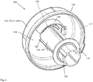
- Fig. 4 shows a bottom view of a third housing part of the in Fig. 1 shown filling head according to another embodiment.
- Fig. 4 shows a bottom view of a third housing part of the in Fig. 1 shown filling head according to another embodiment.
- Fig. 4 shows a bottom view of a third housing part of the in Fig. 1 shown filling head according to another embodiment.
- For the detailed design of the filling is on the comments in the Fig. 1 directed.
- connection piece 123 On an inner side 144 of the third housing part 103-3 of the housing 103 of the filling head 100 of the connecting piece 123 is formed. In order to ensure a pressure equalization in the connection piece 123, at least one pressure equalization opening 125 is arranged in the connection piece 123. On an outer side 127 of the connecting piece 123, a spacer element 129 for generating a ventilation channel in the region of the pressure compensation opening 125 is arranged. Since the pressure compensation opening 125 in the in Fig. 4 view is not visible, the pressure compensation opening 125 in the Fig. 4 only indicated schematically.
- a surge element 131 is arranged, which brakes back flowing liquid.
- a recess 133 is formed, in which a projection of the surge element 131 is inserted.
- the recess 133 is formed at the lower end of the connecting piece 123 and allows pushing the surge element 131 along a longitudinal direction of the connecting piece 123.
- a deflector wall 145 is formed, wherein the deflector wall 145 extends at least in sections along the longitudinal axis of the connecting piece 123 and at least partially surrounds at least one pressure compensation opening 125 in order to prevent liquid from penetrating into the pressure equalization opening 125 prevent.
- the deflector wall 145 is in this case designed, in particular, as a curved deflector wall 145, which rotates the inner side 144 of the third housing part 103-3 at least in sections.
- Deflektorwand 145 can be ensured that 100 penetrating through the outlet port 119 into a housing interior 111 of the housing 103 of the Beglallkopfes 100 liquid can not penetrate uncontrollably in the pressure compensation opening 125, but can be stopped and deflected by the deflector 145.
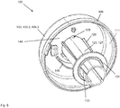
- Fig. 5 shows another view of the in Fig. 4 shown filling head.
- the pressure compensation opening 125 is visible and marked.
- the further characteristics becomes on the remarks in relation to the Fig. 4 directed.
Landscapes
- Engineering & Computer Science (AREA)
- Life Sciences & Earth Sciences (AREA)
- Sustainable Development (AREA)
- Sustainable Energy (AREA)
- Chemical & Material Sciences (AREA)
- Combustion & Propulsion (AREA)
- Transportation (AREA)
- Mechanical Engineering (AREA)
- Filling Or Discharging Of Gas Storage Vessels (AREA)
- Exhaust Gas After Treatment (AREA)
- Cooling, Air Intake And Gas Exhaust, And Fuel Tank Arrangements In Propulsion Units (AREA)
Abstract
Description
- Die vorliegende Erfindung betrifft einen Befüllkopf für einen Flüssigkeitstank in einem Fahrzeug.
- In herkömmlichen Fahrzeugen werden oftmals abgegebene Abgase im Rahmen eines Abgasreinigungsverfahrens mittels selektiver katalytischer Reduktion (SCR) gereinigt, wobei hierbei wässrige Harnstofflösung dem Abgasstrang zugeführt wird. Um die dafür benötige Harnstofflösung aufzunehmen weisen herkömmliche Fahrzeuge Flüssigkeitstanks, insbesondere Harnstofftanks, auf. Bei der Betankung eines Flüssigkeitstanks mit einer wässrigen Harnstofflösung wird die Flüssigkeit oftmals mit einer Befüllgeschwindigkeit von bis zu 40 l/min zugeführt. Hierbei soll vermieden werden, dass während des Betankungsvorgangs Flüssigkeit aus einem Befüllkopf austritt und das Äußere des Fahrzeugs oder die Umwelt verschmutzt.
- Die Druckschrift
DE 10 2011 009 745 A1 beschreibt in diesem Zusammenhang einen Einfüllstutzen für einen Nebenflüssigkeitsbehälter für ein Fahrzeug. - Es ist die der Erfindung zugrundeliegende Aufgabe, einen verbesserten Befüllkopf anzugeben, mit welchem ein Austreten von Flüssigkeit beim Betanken wirksam verhindern werden kann.
- Diese Aufgabe wird durch den Gegenstand mit den Merkmalen nach dem unabhängigen Anspruch gelöst. Vorteilhafte Ausführungsformen der Erfindung sind Gegenstand der Figuren, der Beschreibung und der abhängigen Ansprüche.
- Gemäß einem Aspekt der Erfindung wird die Aufgabe durch einen Befüllkopf für einen Flüssigkeitstank in einem Fahrzeug gelöst, mit einem Gehäuse, das ein erstes Gehäuseteil, ein zweites Gehäuseteil und ein drittes Gehäuseteil aufweist, wobei das dritte Gehäuseteil mit dem ersten Gehäuseteil und mit dem zweiten Gehäuseteil verbunden ist, wobei in dem ersten Gehäuseteil eine Aufnahmeöffnung gebildet ist, wobei in die Aufnahmeöffnung ein Zapfventil zum Einlassen von Flüssigkeit einführbar ist, wobei in dem zweiten Gehäuseteil ein Entlüftungsstutzen zum Einleiten von Luft in das Innere des Gehäuses gebildet ist, wobei in dem dritten Gehäuseteil ein Verbindungsstutzen zum Leiten von Flüssigkeit gebildet ist, wobei der Verbindungsstutzen in dem Gehäuse zwischen dem dritten Gehäuseteil und dem zweiten Gehäuseteil angeordnet ist, und wobei der Verbindungsstutzen zumindest eine Druckausgleichsöffnung zum Druckausgleich in dem Verbindungsstutzen umfasst.
- Durch den Befüllkopf können hohe Befüllgeschwindigkeiten von bis zu 40 l/min ermöglicht werden, ohne dass es zu einem Austritt von Flüssigkeit aus der Aufnahmeöffnung des ersten Gehäuseteils kommt. Bei hohen Befüllgeschwindigkeit von bis zu 40 l/min muss die durch die eingeleitete Flüssigkeit aus dem Flüssigkeitstank verdrängte Luft aus dem Befüllkopf ausgeleitet werden. Hierbei weist das zweite Gehäuseteil insbesondere einen mit dem Flüssigkeitstank fluidtechnisch verbindbaren Auslassstutzen zum Auslassen der zugeführten Flüssigkeit in den Flüssigkeitstank auf, wobei insbesondere die aus dem Flüssigkeitstank beim Einleiten von Flüssigkeit verdrängte Luft durch den Auslassstutzen entgegen der Strömungsrichtung der Flüssigkeit aus dem Flüssigkeitstank in den Befüllkopf strömen kann.
- Durch die Druckausgleichsöffnung in dem Verbindungsstutzen kann ein wirksamer Druckausgleich zwischen dem Innenraum des Verbindungsstutzens und einem Gehäuseinnenraum des Gehäuses des Befüllkopfes sichergestellt werden, um ein Aufspritzen von Flüssigkeit in dem Verbindungsstutzen zu reduzieren. Dadurch können die hohen Befüllgeschwindigkeiten von bis zu 40 l/min aufrechterhalten werden und zudem kann ein Aufspritzen der zugeführten Flüssigkeit und ein möglicherweise auftretendes Austreten der Flüssigkeit aus dem Befüllkopf verhindert werden.
- In einer vorteilhaften Ausführungsform des Befüllkopfes ist die zumindest eine Druckausgleichsöffnung des Verbindungsstutzens als eine im Querschnitt kreisförmige, V-förmige und/oder U-förmige Druckausgleichsöffnung ausgebildet, wobei die Druckausgleichsöffnung insbesondere als eine sich verjüngende Druckausgleichsöffnung ausgebildet ist, welche sich von einem der Aufnahmeöffnung zugewandten Ende der Druckausgleichsöffnung zu einem dem Entlüftungsstutzen zugewandten Ende der Druckausgleichsöffnung verjüngt.
- Dadurch wird beispielsweise der technische Vorteil erreicht, dass durch die zumindest eine im Querschnitt kreisförmige, V-förmige und/oder U-förmige Druckausgleichsöffnung eine besonders wirksame Luftströmung beim Luftaustausch ermöglicht wird. Hierbei ist die Druckausgleichsöffnung insbesondere als eine sich verjüngende Druckausgleichsöffnung ausgebildet, welche sich von einem der Aufnahmeöffnung zugewandten Ende der Druckausgleichsöffnung zu einem dem Entlüftungsstutzen zugewandten Ende der Druckausgleichsöffnung verjüngt, wodurch eine vorteilhafte Luftführung gewährleistet wird. Dadurch wird der Vorteil erreicht, dass an einem dem Entlüftungsstutzen zugewandten Ende der Druckausgleichsöffnung aufgrund der sich verjüngenden Form die Menge der möglicherweise durch die Druckausgleichsöffnung tretenden Flüssigkeit reduziert werden kann.
- In einer vorteilhaften Ausführungsform des Befüllkopfes weist das dritte Gehäuseteil eine dritte Gehäusewand auf, weist das zweite Gehäuseteil eine zweite Gehäusewand auf, und sind die dritte Gehäusewand und die zweite Gehäusewand miteinander verbunden und begrenzen einen Gehäuseinnenraum, wobei sich der Verbindungsstutzen von der dritten Gehäusewand aus in den Gehäuseinnenraum erstreckt, und wobei die Druckausgleichsöffnung des Verbindungsstutzens insbesondere im Bereich der dritten Gehäusewand angeordnet ist.
- Dadurch wird beispielsweise der technische Vorteil erreicht, dass der durch das zweite und dritte Gehäuseteil begrenzte Gehäuseinnenraum ein wirksames Ausleiten von aufgenommener Luft ermöglicht. Dadurch, dass die Druckausgleichsöffnung an dem Verbindungsstutzen im Bereich der dritten Gehäusewand angeordnet ist, welche der Aufnahmeöffnung zugewandt ist, kann besonders wirksam verhindert werden, das Flüssigkeit, die sich möglicherweise im unteren Bereich des Gehäuseinnenraums gesammelt hat, durch die Druckausgleichsöffnung entweicht.
- In einer vorteilhaften Ausführungsform des Befüllkopfes weist das zweite Gehäuseteil oder das dritte Gehäuseteil einen Einführabschnitt auf, welcher in einen Aufnahmeabschnitt des dritten Gehäuseteils oder des zweiten Gehäuseteils einführbar ist, um das zweite Gehäuseteil und das dritte Gehäuseteil miteinander zu verbinden.
- Dadurch wird beispielsweise der technische Vorteil erreicht, dass eine besonders wirksame Verbindung zwischen dem zweiten Gehäuseteil und dem dritten Gehäuseteil sichergestellt wird.
- In einer vorteilhaften Ausführungsform des Befüllkopfes ist der Verbindungsstutzen als ein Hohlzylinder oder als ein Hohlkonus gebildet.
- Dadurch wird beispielsweise der technische Vorteil erreicht, dass beim Zuführen der Flüssigkeit eine gute Führungswirkung und ein laminarer oder turbulenzfreier Strömungsfluss in dem Verbindungsstutzen sichergestellt werden kann. Bei der Herstellung des Hohlzylinders im Rahmen eines Spritzgussverfahrens kann der Hohlzylinder insbesondere eine Entformschräge aufweisen.
- In einer vorteilhaften Ausführungsform des Befüllkopfes ist an einer Außenseite des Verbindungsstutzens zumindest ein Abstandselement gebildet, wobei das Abstandselement geformt ist, einen Entlüftungskanal im Bereich der Druckausgleichsöffnung zu bilden.
- Dadurch wird beispielsweise der technische Vorteil erreicht, dass der Entlüftungskanal zwischen dem Verbindungsstutzen und dem Gehäuse des Befüllkopfes eine wirksame Entlüftung von Luft aus dem Befüllkopf sicherstellt.
- In einer vorteilhaften Ausführungsform des Befüllkopfes wird das Abstandselement durch eine Längsrippe gebildet, die sich zumindest abschnittsweise entlang einer Längsachse des Verbindungsstutzens erstreckt.
- Dadurch wird beispielsweise der technische Vorteil erreicht, dass die Längsrippe eine wirksame Beabstandung sicherstellt und zudem die Stabilität des Verbindungsstutzens verbessert.
- In einer vorteilhaften Ausführungsform des Befüllkopfes erstreckt sich der Entlüftungsstutzen parallel zum Verbindungsstutzen.
- Dadurch wird beispielsweise der technische Vorteil erreicht, dass der Befüllkopf besonders raumsparend gestaltet ist, da verhindert wird, dass der Befüllkopf eine Vielzahl von Anschlüssen aufweist, welche sich von dem Befüllkopf in unterschiedliche Richtungen erstrecken.
- In einer vorteilhaften Ausführungsform des Befüllkopfes umfasst der Befüllkopf einen Ringmagneten, welcher ausgebildet ist, eine Zapfventilautomatik des Zapfventils freizugeben, und wobei der Ringmagnet insbesondere aus einem magnetischen Kunststoffmaterial gebildet ist.
- Dadurch wird beispielsweise der technische Vorteil erreicht, dass eine Fehlbetankung des Flüssigkeitstanks verhindert werden kann. Das Zapfventil weist eine Zapfventilautomatik auf, welche durch den Ringmagneten freigegeben wird, so dass verhindert werden kann, dass beispielsweise durch das Zapfventil abgegebene Harnstofflösung ohne magnetische Wechselwirkung mit dem Ringmagnet abgegeben werden kann. Somit kann sichergestellt werden, dass z.B. bei Dieselfahrzeugen, keine Harnstofflösung in einen Dieseltank eingefüllt werden kann. Der Ringmagnet besteht hierbei aus einem magnetischen Kunststoff, insbesondere einem durch einen Spritzguss hergestellten Kunststoffring, welcher magnetische Partikel, z.B. Eisen-Partikel und/oder Seltene Erd-Partikel wie Neodym-Partikel, aufweist, um die magnetischen Eigenschaften des Ringmagnets bereitzustellen.
- In einer vorteilhaften Ausführungsform des Befüllkopfes ist der Ringmagnet zwischen dem ersten Gehäuseteil und dem dritten Gehäuseteil angeordnet, wobei der Ringmagnet eine Magnetöffnung aufweist, wobei das Zapfventil durch die Magnetöffnung in eine Aufnahme des Verbindungsstutzens einführbar ist, und wobei der Ringmagnet insbesondere als ein in Richtung des ersten Gehäuseteils konisch zulaufender Ringmagnet ausgebildet ist.
- Dadurch wird beispielsweise der technische Vorteil erreicht, dass das Zapfventil durch die Aufnahmeöffnung des ersten Gehäuseteils und durch die Magnetöffnung des Ringmagnets wirksam in den Verbindungsstutzen eingeführt werden kann. Hierbei umschließt der Ringmagnet das Zapfventil vorteilhaft und kann dadurch die Zapfventilautomatik des Zapfventils wirksam auslösen. Insbesondere durch die in Richtung des ersten Gehäuseteils konisch zulaufende Form des Ringmagnets kann eine besonders wirksame Aufnahme des Ringmagnets in einer entsprechenden Aufnahme des Befüllkopfes in dem ersten Gehäuseteil sichergestellt werden.
- In einer vorteilhaften Ausführungsform des Befüllkopfes weist der Befüllkopf einen Dichtungsring auf, wobei der Dichtungsring zwischen dem Ringmagneten und dem ersten Gehäuseteil angeordnet ist, wobei der Dichtungsring eine Dichtungsöffnung aufweist, und wobei das Zapfventil durch die Dichtungsöffnung in eine Aufnahme des Verbindungsstutzens einführbar ist.
- Dadurch wird beispielsweise der technische Vorteil erreicht, dass der Dichtungsring eine fluidtechnische Abdichtung des Bereichs zwischen dem Ringmagneten und dem Gehäuse ermöglicht, wodurch verhindert werden kann, dass Flüssigkeit unkontrolliert in den Befüllkopf eindringen kann.
- In einer vorteilhaften Ausführungsform des Befüllkopfes weist der Dichtungsring einen Ringrand und eine umlaufende Dichtungsrippe auf, wobei sich die umlaufende Dichtungsrippe von dem Ringrand aus umlaufend in die Dichtungsöffnung erstreckt.
- Dadurch wird beispielsweise der technische Vorteil erreicht, dass die Dichtungsrippe besonders vorteilhaft an dem durch die Dichtungsöffnung des Dichtungsrings eingeführten Zapfventils anliegt und damit eine besonders wirksame fluidtechnische Abdichtung sicherstellt.
- In einer vorteilhaften Ausführungsform des Befüllkopfes umfasst der Verbindungsstutzen ein Schwallelement, insbesondere ein ringförmiges Schwallelement, das mit dem Verbindungsstutzen verbindbar ist.
- Dadurch wird beispielsweise der technische Vorteil erreicht, dass das Schwallelement, ein Zurückschwallen, bzw. Zurückspritzen, von Flüssigkeit aus dem Flüssigkeitstank in den Befüllkopf verhindern kann.
- In einer vorteilhaften Ausführungsform des Befüllkopfes ist an einer Außenseite des Verbindungsstutzens eine Aussparung gebildet, wobei das Schwallelement einen Vorsprung aufweist, wobei der Vorsprung in die Aussparung einführbar ist, um das Schwallelement mit dem Verbindungsstutzen zu verbinden, und wobei das Schwallelement insbesondere durch eine Bajonett-Verbindung mit dem Verbindungsstutzen verbindbar ist.
- Dadurch wird beispielsweise der technische Vorteil erreicht, dass durch das Einführen des Vorsprungs des Schwallelements in die Aussparung des Verbindungsstutzens eine besonders wirksame Fixierung des Schwallelements an dem Verbindungsstutzen sichergestellt wird.
- In einer vorteilhaften Ausführungsform des Befüllkopfes ist an einer Außenseite des Verbindungsstutzens zumindest eine Längsrippe gebildet, welche sich zumindest abschnittsweise entlang einer Längsachse des Verbindungsstutzens erstreckt, wobei die Längsrippe insbesondere einen Anschlag für das mit dem Verbindungsstutzen verbundene Schwallelement aufweist.
- Dadurch wird beispielsweise der technische Vorteil erreicht, dass sich durch die Längsrippe die Halterung des Schwallelementes verbessert und an dem Schwallelement auftretende Kräfte besser auf den Verbindungsstutzen übertragen werden können. Durch den durch die Längsrippe gebildeten Anschlag für das Schwellelement kann ein Verrutschen des Schwallelements an dem Verbindungsstutzen verhindert werden.
- In einer vorteilhaften Ausführungsform des Befüllkopfes ist an einer Innenseite des dritten Gehäuseteils eine Deflektorwand geformt, wobei sich die Deflektorwand zumindest abschnittsweise entlang einer Längsachse des Verbindungsstutzens erstreckt und die zumindest eine Druckausgleichsöffnung zumindest teilweise umschließt, um ein Eindringen von Flüssigkeit in die Druckausgleichsöffnung zu verhindern, und wobei die Deflektorwand insbesondere als eine gebogene Deflektorwand ausgebildet ist, welche die Innenseite des dritten Gehäuseteils zumindest abschnittsweise umläuft.
- Insbesondere ist die Deflektorwand in einem Gehäuseinnenraum des Befüllkopfes auf einer gegenüberliegenden Seite des Entlüftungsstutzens angeordnet, um aufwallende Flüssigkeit vom Entlüftungspfad abzuleiten.
- Dadurch wird beispielsweise der technische Vorteil erreicht, dass die Deflektorwand sicherstellt, dass durch den Auslassstutzen in einen Gehäuseinnenraum des Gehäuses des Befüllkopfes einströmende Flüssigkeit nicht unkontrolliert in die Druckausgleichsöffnung eindringen kann, sondern durch die Deflektorwand aufgehalten und abgeleitet werden kann.
- Ausführungsbeispiele der Erfindung sind in den Zeichnungen dargestellt und werden im Folgenden näher beschrieben.
- Es zeigen:
-
Fig. 1 eine perspektivische Außenansicht eines Befüllkopfes; -
Fig. 2 eine Querschnittsansicht eines Befüllkopfes; -
Fig. 3 eine vergrößerte Querschnittsansicht des inFig. 2 dargestellten Befüllkopfes; -
Fig. 4 zeigt eine Unteransicht eines dritten Gehäuseteils des inFig. 1 dargestellten Befüllkopfes gemäß einer weiteren Ausführungsform; und -
Fig. 5 zeigt eine weitere Ansicht des inFig. 4 dargestellten Befüllkopfes. -
Fig. 1 zeigt eine perspektivische Außenansicht eines Befüllkopfes 100 in einer Explosionsdarstellung. - Der Befüllkopf 100 weist ein Gehäuse 103 auf, das aus einem ersten Gehäuseteil 103-1, einem zweiten Gehäuseteil 103-2 und einem dritten Gehäuseteil 103-3 zusammengesetzt ist. Hierbei ist das dritte Gehäuseteil 103-3 zwischen dem ersten Gehäuseteil 103-1 und dem zweiten Gehäuseteil 103-2 angeordnet. Das dritte Gehäuseteil 103-3 ist mit dem ersten Gehäuseteil 103-1 und ist mit dem zweiten Gehäuseteil 103-2 verbunden.
- Das erste Gehäuseteil 103-1 weist eine erste Gehäusewand 105-1 auf. Das zweite Gehäuseteil 103-2 weist eine zweite Gehäusewand 105-2 auf. Das dritte Gehäuseteil 103-3 weist eine dritte Gehäusewand 105-3 auf. Die zweite Gehäusewand 105-2 weist einen Einführabschnitt 107 auf, welcher in einen Aufnahmeabschnitt 109 der dritten Gehäusewand 105-3 einführbar ist, um das zweite Gehäuseteil 103-2 mit dem dritten Gehäuseteil 103-3, insbesondere formschlüssig, zu verbinden. Somit begrenzen die zweite Gehäusewand 105-2 des zweiten Gehäuseteils 103-2 und die dritte Gehäusewand 105-3 des dritten Gehäuseteils 103-3 einen in
Fig. 1 nur schematisch dargestellten Gehäuseinnenraum 111. - An einer dem ersten Gehäuseteil 103-1 zugewandten Seite der zweiten Gehäusewand 105-2 schließt die erste Gehäusewand 105-1 des ersten Gehäuseteils 103-1 den Gehäuseinnenraum 111 ab.
- Zwischen dem zweiten Gehäuseteil 103-2 und dem ersten Gehäuseteil 103-1 ist ein Ringmagnet 113 angeordnet. Der Ringmagnet 113 umfasst insbesondere ein magnetisches Kunststoffmaterial, insbesondere ein Kunststoffmaterial, in dem magnetische Füllstoffe, wie z.B. Eisen-Partikel und/oder Seltene Erd-Partikel wie Neodym-Partikel, aufgenommen sind. Der Ringmagnet 113 weist eine in
Fig. 1 nicht gezeigte Magnetöffnung auf, durch welche eine inFig. 1 nicht dargestelltes Zapfventil zum Befüllen eines Flüssigkeitstanks in den Befüllkopf 100 eingeführt werden kann. Der Ringmagnet 113 ist ausgebildet, eine Zapfventilautomatik des Zapfventils freizugeben, damit Flüssigkeit aus dem Zapfventil durch den Befüllkopf 100 in den Flüssigkeitstank geleitet werden kann. Der Ringmagnet 113 ist hierbei insbesondere als ein in Richtung des ersten Gehäuseteils 103-1 konisch zulaufender Ringmagnet 113 ausgebildet und weist eine sich entsprechend verjüngende Form auf, zum Verbau des Ringmagneten 113 in der gewünschten Polarisationsrichtung. - Zwischen dem Ringmagnet 113 und dem ersten Gehäuseteil 103-1 ist ein Dichtungsring 115 angeordnet. Der Dichtungsring 115 weist eine in
Fig. 1 nicht dargestellte Dichtungsöffnung auf, durch welche das Zapfventil geführt werden kann. Der Dichtungsring 115 stellt eine wirksame flüssigkeitsdichte Abdichtung des Gehäuseinnenraums 111 sicher und gewährleistet, dass keine Flüssigkeit aus dem Befüllkopf 100 unkontrolliert entweichen kann. - Zum Betanken eines Flüssigkeitstanks, insbesondere Harnstofftanks, in einem Fahrzeug wird ein in
Fig. 1 nicht dargestelltes Zapfventil in eine Aufnahmeöffnung 117 des ersten Gehäuseteils 103-1 des Befüllkopfes 100 eingeführt, durch eine Aufnahme 116 eines Verbindungsstutzens 123 des dritten Gehäuseteils 103-3 eingeführt und anschließend betätigt. Durch das Zapfventil geförderte Flüssigkeit fließt dann aus dem Zapfventil in den Befüllkopf 100 und durch den Verbindungsstutzen 123 in den inFig. 1 nicht gezeigten Flüssigkeitstank. - In dem zweiten Gehäuseteil 103-2 ist ein Auslassstutzen 119 gebildet, durch den beim Betanken die Flüssigkeit in Richtung des Flüssigkeitstanks fließt. Zu diesem Zweck ist an dem Auslassstutzen 119 beispielsweise ein in
Fig. 1 nicht gezeigter Schlauch oder eine Flüssigkeitsleitung aufgesteckt, welche mit dem Flüssigkeitstanks verbunden ist. - Hierbei ist der Flüssigkeitstank insbesondere als ein Harnstofftank zur Aufnahme einer wässrigen Harnstofflösung ausgebildet, wobei die darin aufgenommene Harnstofflösung in einem Abgasreinigungsverfahren mittels selektiver katalytischer Reduktion (SCR) eingesetzt wird.
- Durch den Befüllkopf 100 wird die sachgerechte Entlüftung beim Betanken auch bei hohen Befüllgeschwindigkeiten von bis zu 40 l/min sichergestellt und das Austreten der Flüssigkeit aus der Aufnahmeöffnung 117 wird verhindert. Aus dem Flüssigkeitstank hierbei verdrängte Luft wird in den Befüllkopf 100 eingeleitet. Die eingeleitete Luft wird in dem Befüllkopf 100 von der Flüssigkeit separiert, damit diese keine Flüssigkeit mitreißt und somit verhindert wird, dass Flüssigkeit durch die Aufnahmeöffnung 117 aus dem Befüllkopf 100 in Richtung eines Bedieners des Zapfventils austreten oder entweichen kann.
- Hierzu ist in dem zweiten Gehäuseteil 103-2 ein Entlüftungsstutzen 121 gebildet, welcher sich insbesondere parallel zudem Verbindungsstutzen 123 und/oder zu dem Auslassstutzen 119 erstreckt. Durch den Entlüftungsstutzen 121 wird in den Befüllkopf 100 das Luftvolumen eingeleitet, das beim Zuführen von Flüssigkeit in den Flüssigkeitstank aus dem Flüssigkeitstank verdrängt wird, damit dieses dann über die Aufnahmeöffnung 117 des Befüllkopfes 100 ausgeleitet werden kann. Zu diesem Zweck ist beispielsweise ein in
Fig. 1 nicht gezeigter Entlüftungsschlauch an dem Entlüftungsstutzen 121 angeschlossen, wobei der Entlüftungsschlauch fluidtechnisch mit dem Flüssigkeitstank verbunden ist. Die Aufnahmeöffnung 117 ist derart ausgebildet, dass bei einem in die Aufnahmeöffnung 117 aufgenommenen Zapfventil ein Entlüftungskanal um das Zapfventil herum entsteht. Dies wird beispielsweise durch ein Nutprofil erreicht, welches ein Inneres der Aufnahmeöffnung 117 umläuft. Der Entlüftungskanal im Inneren des Befüllkopfes 100 ist derart gestaltet, dass selbst bei einer Befüllgeschwindigkeit der Flüssigkeit von 40 l/min ebenfalls Luft mit einer Entlüftungsgeschwindigkeit von 40 l/min durch den Befüllkopf 100 entweichen kann. - Der Entlüftungsstutzen 121 erstreckt sich in der gleichen Richtung wie der Auslassstutzen 119, so dass ein raumsparender Einbau des Befüllkopfes 100 innerhalb des Fahrzeuges ermöglicht wird. Anschlussleitungen für den Entlüftungsstutzen 121 und den Auslassstutzen 119 können dann von der gleichen Richtung her aufgesteckt werden.
- Im dritten Gehäuseteil 103-3 ist ein Verbindungsstutzen 123 gebildet, der das Zapfventil aufnimmt, positioniert und den Strahl der eingefüllten Flüssigkeit wirksam leiten kann. Der Verbindungsstutzen 123 ist insbesondere als ein Hohlzylinder ausgebildet und erstreckt sich von der dritten Gehäusewand 105-3 des dritten Gehäuseteils 103-3 aus in den Gehäuseinnenraum 111, und erstreckt sich hierbei insbesondere in den Bereich des zweiten Gehäuseteils 103-2. Der Verbindungsstutzen 123 ist jedoch ein integraler Bestandteil des dritten Gehäuseteils 103-3.
- Beim Betanken strömt die verdrängte Luft über den Entlüftungsstutzen 121 in den Gehäuseinnenraum 111 ein und verursacht im Gehäuseinnenraum 111 einen leichten Überdruck. Dieser Überdruck wirkt als Luftpolster und drückt Flüssigkeit, die sich möglicherweise im Befüllkopf 100 befindet, in Richtung des Auslassstutzens 119.
- Um einen Druckausgleich in dem Verbindungsstutzen 123 sicherzustellen, ist in dem Verbindungsstutzen 123 zumindest eine in
Fig. 1 nur schematisch dargestellte Druckausgleichsöffnung 125 zum teilweise Ausleiten der durch den Entlüftungsstutzen 121 eingeleiteten Luft in das Innere des Gehäuses 103 angeordnet. Die Druckausgleichsöffnung 125 ist in der inFig. 1 dargestellten Ansicht nur schematisch gezeigt. Die Größe und Form der Druckausgleichsöffnung 125 ist derart gewählt, dass kein Rückstau an Luft, bzw. kein Unterdruck im Verbindungsstutzen 123 entsteht, und dass aufgrund von in den Gehäuseinnenraum 111 eindringender Flüssigkeit es nicht zu einer Frühabschaltung des Zapfventils kommt, so dass keine Flüssigkeit aus dem Befüllkopf 100 austreten kann. Die Position der Druckausgleichsöffnung 125 ist derart gewählt, dass zum einen Luft solange wie möglich entweichen kann und zum anderen ein Austritt von Flüssigkeit verhindert werden kann. Dementsprechend sind Position, Höhe, Breite der Druckausgleichsöffnung 125 aufeinander abgestimmt. - Die zumindest eine Druckausgleichsöffnung 125 ist beispielsweise durch eine kreisförmige, V-förmige und/oder U-förmige Druckausgleichsöffnung 125 in dem Verbindungsstutzen 123 gebildet, wobei die Druckausgleichsöffnung 125 insbesondere im Bereich der dritten Gehäusewand 105-3 in dem Verbindungsstutzen 123 angeordnet ist. Dadurch kann Flüssigkeit in dem Gehäuseinnenraum 111 aufsteigen, während die durch den Entlüftungsstutzen 121 ausgeleitete Luft möglichst lange aus dem Befüllkopf 100 entweichen kann.
- Hierbei ist die Druckausgleichsöffnung 125 insbesondere als eine sich verjüngende Druckausgleichsöffnung 125 ausgebildet ist, welche sich von einem der Aufnahmeöffnung 117 zugewandten Ende 124 der Druckausgleichsöffnung 125 zu einer dem Entlüftungsstutzen 121 zugewandten Ende 126 der Druckausgleichsöffnung 125 verjüngt. Dadurch kann eine vorteilhafte Luftausleitung aus der Druckausgleichsöffnung 125 sichergestellt werden, und es kann gleichzeitig wirksam verhindert werden, dass Flüssigkeit durch die Druckausgleichsöffnung 125 austritt.
- An einer Außenseite 127 des Verbindungsstutzens 123 ist ein Abstandselement 129 zum Erzeugen eines Entlüftungskanales im Bereich der Druckausgleichsöffnung 125 angeordnet. Das Abstandselement 129 umfasst insbesondere Längsrippen, welche die Stabilität des Verbindungsstutzens 123 verbessern. Das Abstandselement 129 dient der Beabstandung der Druckausgleichsöffnung 125 von der dritten Gehäusewand 105-3, so dass sich zwischen dem Verbindungsstutzen 123 und der dritten Gehäusewand 105-3 im Bereich der Druckausgleichsöffnung 125 ein vorteilhafter Entlüftungskanal gebildet wird.
- Die Gehäuseteile 103-1, 103-2 und 103-3 sind beispielsweise Kunststoff- oder Spritzgussformteile aus Polyamid (PA), Polyoxymethylen (POM), Polyolefin oder thermoplastischen Elastomeren auf Olefinbasis. Die Fertigung der Gehäuseteile 103-1, 103-2 und 103-3 aus diesen Materialien ist besonders vorteilhaft, da hierdurch eine hohe Festigkeit und Stabilität des Befüllkopfes 100 erreicht wird.
- An einem unteren, dem Auslassstutzen 119 zugewandten, Ende des Verbindungsstutzens 123 ist ein Schwallelement 131 angeordnet, das eine zurückströmende Flüssigkeit abbremst und verhindert, dass der Gehäuseinnenraum 111 des Befüllkopfes 100 vollständig geflutet wird. Das Schwallelement 131 ist als separates Teil an dem Verbindungsstutzen 123 im Befüllkopf 100 befestigt. Somit ist es möglich die Abstimmung auf verschiedene Tanksysteme vorzunehmen und ein Baukastensystem zu erstellen.
- An der Außenseite 127 des Verbindungsstutzens 123 ist eine Aussparung 133 gebildet, in die ein in
Fig. 1 nicht gezeigter Vorsprung des Schwallelementes 131 eingesetzt wird. Die Aussparung 133 ist an dem unteren Ende des Verbindungsstutzens 123 gebildet und ermöglicht ein Aufschieben des Schwallelementes 131 entlang einer Längsrichtung des Verbindungsstutzens 123. Zusätzlich ist die Aussparung 133 derart gebildet, dass das Schwallelement 131 nach dem Aufschieben in die Aussparung 133 durch eine Drehung an dem Verbindungsstutzen 123 fixiert werden kann. Die Aussparung 133 kann derart gestaltet sein, dass eine Befestigung des Schwallelementes 131 an dem Verbindungsstutzen 123 insbesondere mittels eines Bajonettverschlusses erreicht wird. Weiter kann in der Aussparung 133 ein Rastsystem vorgesehen sein, das ein Lösen des Schwallelementes 131 verhindert und die Montagestellung des modularen Schwallelementes 131 verhindert. - An dem insbesondere als Längsrippen ausgebildeten Abstandselement 129 ist ein Anschlag gebildet, an welchem das Schwallelement 131 anliegt. Dadurch wird das Schwallelement 131 zusätzlich in seiner Lage stabilisiert und unterstützt, so dass ein Verrutschen des Schwallelementes 131 im Inneren des Befüllkopfes 100 verhindert werden kann.
-
Fig. 2 zeigt eine Querschnittsansicht eines Befüllkopfes 100. - Das Gehäuse 103 des Befüllkopfes 100 umfasst ein erstes Gehäuseteil 103-1, ein zweites Gehäuseteil 103-2 und ein drittes Gehäuseteil 103-3. Hierbei ist das dritte Gehäuseteil 103-3 zwischen dem ersten Gehäuseteil 103-1 und dem zweiten Gehäuseteil 103-2 angeordnet, und ist das dritte Gehäuseteil 103-3 mit dem ersten Gehäuseteil 103-1 und dem zweiten Gehäuseteil 103-2 verbunden.
- Das erste Gehäuseteil 103-1 weist eine erste Gehäusewand 105-1 auf. Das zweite Gehäuseteil 103-2 weist eine zweite Gehäusewand 105-2 auf. Das dritte Gehäuseteil 103-3 weist eine dritte Gehäusewand 105-3 auf. Die zweite Gehäusewand 105-2 weist einen Einführabschnitt 107 auf, welcher in einen Aufnahmeabschnitt 109 der dritten Gehäusewand 105-3 einführbar ist. Somit begrenzen die zweite Gehäusewand 105-2 und die dritte Gehäusewand 105-3 einen in
Fig. 1 nur schematisch dargestellten Gehäuseinnenraum 111. - An einer dem ersten Gehäuseteil 103-1 zugewandten Seite der zweiten Gehäusewand 105-2 schließt die erste Gehäusewand 105-1 des ersten Gehäuseteils 103-1 den Gehäuseinnenraum 111 ab.
- Zwischen dem zweiten Gehäuseteil 103-2 und dem ersten Gehäuseteil 103-1 ist ein Ringmagnet 113 zum Freigeben einer Zapfventilautomatik eines Zapfventils angeordnet. Zwischen dem Ringmagnet 113 und dem ersten Gehäuseteil 103-1 ist ein Dichtungsring 115 angeordnet. Der Dichtungsring 115 weist insbesondere eine umlaufende Dichtungsrippe 137 auf, welche sich von einem Ringrand 139 des Dichtungsrings 115 in eine Dichtungsöffnung 141 des Dichtungsrings 115 erstreckt.
- Ein in
Fig. 2 nicht dargestelltes Zapfventil wird durch eine Aufnahmeöffnung 117 des ersten Gehäuseteils 103-1, durch die Dichtungsöffnung 141 in dem Dichtungsring 115, durch eine Magnetöffnung 143 in dem Ringmagnet 113 und durch eine Aufnahme 116 des Verbindungsstutzens 123 in den Verbindungsstutzen 123 des dritten Gehäuseteils 103-3 eingeführt, um die von dem Zapfventil abgegebene Flüssigkeit durch den Verbindungsstutzen 123 zu leiten. - Ferner weist das zweite Gehäuseteil 103-2 einen Auslassstutzen 119 zum Auslassen der zugeführten Flüssigkeit aus dem Befüllkopf 100 auf und weist das zweite Gehäuseteil 103-2 einen in der in
Fig. 2 nicht sichtbaren Entlüftungsstutzen 121 zum Entlüften des Befüllkopfes 100 auf. - An einer Außenseite 127 des Verbindungsstutzens 123 ist zumindest eine Druckausgleichsöffnung 125, insbesondere eine im Querschnitt kreisförmige, V-förmige und/oder U-förmige Druckausgleichsöffnung 125 in dem Verbindungsstutzen 123, gebildet. Die Druckausgleichsöffnung 125 ist an einem dem ersten Gehäuseteil 103-1 zugewandten Ende des Verbindungsstutzens 123 angeordnet. Dadurch kann Flüssigkeit in dem Gehäuseinnenraum 111 aufsteigen, während die durch den Entlüftungsstutzen 121 eingeführte Luft möglichst lange durch die Druckausgleichsöffnung 125 entweichen kann.
- An einer Außenseite 127 des Verbindungsstutzens 123 ist ein Abstandselement 129, insbesondere Längsrippen, zum Erzeugen eines Entlüftungskanales im Bereich der Druckausgleichsöffnung 125 angeordnet.
- Am unteren Ende des Verbindungsstutzens 123 ist ein Schwallelement 131 angeordnet, das eine zurückströmende Flüssigkeit abbremst und verhindert, dass der Gehäuseinnenraum 111 des Befüllkopfes 100 vollständig geflutet wird. Das Schwallelement 131 weist einen Vorsprung auf, welcher in eine Aussparung 133 des Verbindungsstutzens 123 eingeführt ist, um das Schwallelement 131 mit dem Verbindungsstutzen 123 zu verbinden.
-
Fig. 3 zeigt eine vergrößerte Querschnittsansicht des inFig. 2 dargestellten Befüllkopfes 100. - Das in
Fig. 3 dargestellte erste Gehäuseteil 103-1 des Gehäuses 103 ist nur abschnittsweise dargestellt. Die zweite Gehäusewand 105-2 des zweiten Gehäuseteils 103-2 weist einen Einführabschnitt 107 auf, welcher in einen Aufnahmeabschnitt 109 der dritten Gehäusewand 105-3 des dritten Gehäuseteils 103-3 eingeführt ist. Somit begrenzen die zweite Gehäusewand 105-2 und die dritte Gehäusewand 105-3 einen inFig. 1 nur schematisch dargestellten Gehäuseinnenraum 111. - Zwischen dem zweiten Gehäuseteil 103-2 und dem ersten Gehäuseteil 103-1 ist ein Ringmagnet 113 zum Freigeben einer Zapfventilautomatik eines Zapfventils angeordnet. Zwischen dem Ringmagnet 113 und dem ersten Gehäuseteil 103-1 ist ein Dichtungsring 115 angeordnet. Der Dichtungsring 115 weist insbesondere eine umlaufende Dichtungsrippe 137 auf, welche sich von einem Ringrand 139 des Dichtungsrings 115 in die Dichtungsöffnung 141 des Dichtungsrings 115 erstreckt.
- Ein in
Fig. 3 nicht dargestelltes Zapfventil wird durch eine inFig. 3 nicht dargestellte Aufnahmeöffnung 117 des ersten Gehäuseteils 103-1, durch eine Dichtungsöffnung 141 in dem Dichtungsring 115, durch eine Magnetöffnung 143 in dem Ringmagnet 113, und durch eine Aufnahme 116 des Verbindungsstutzens 123 in den Verbindungsstutzen 123 des dritten Gehäuseteils 103-3 eingeführt, um Flüssigkeit durch den Verbindungsstutzen 123 in Richtung des Flüssigkeitstanks zu leiten - Ferner weist das Gehäuse 103 noch einen in
Fig. 3 nicht dargestellten Auslassstutzen 119 zum Auslassen der zugeführten Flüssigkeit aus dem Befüllkopf 100 auf und einen in der inFig. 3 nicht sichtbaren Entlüftungsstutzen 121 zum Entlüften des Befüllkopfes 100 auf. - An einer Außenseite 127 des Verbindungsstutzens 123 ist zumindest eine Druckausgleichsöffnung 125, beispielsweise als eine kreisförmige, V-förmige und/oder U-förmige Druckausgleichsöffnung 125 gebildet, welche sich insbesondere von einem der Aufnahmeöffnung 117 zugewandten Ende 124 zu einem dem Entlüftungsstutzen 121 zugewandten Ende 126 verjüngt. Dadurch kann Flüssigkeit in dem Gehäuseinnenraum 111 aufsteigen, während die durch den Entlüftungsstutzen 121 ausgeleitete Luft möglichst lange durch die Druckausgleichsöffnung 125 entweichen kann.
- An einer Außenseite 127 des Verbindungsstutzens 123 ist ein Abstandselement 129, insbesondere Längsrippen, zum Erzeugen eines Entlüftungskanales im Bereich der Druckausgleichsöffnung 125 angeordnet. Ein Schallelement 131 ist in
Fig. 3 nicht dargestellt. -
Fig. 4 zeigt eine Unteransicht eines dritten Gehäuseteils des inFig. 1 dargestellten Befüllkopfes gemäß einer weiteren Ausführungsform. Für die detaillierte Ausgestaltung des Befüllkopfes wird auf die Ausführungen in derFig. 1 verwiesen. - An einer Innenseite 144 des dritten Gehäuseteils 103-3 des Gehäuses 103 des Befüllkopfes 100 ist der Verbindungsstutzen 123 geformt. Um einen Druckausgleich in dem Verbindungsstutzen 123 sicherzustellen, ist in dem Verbindungsstutzen 123 zumindest eine Druckausgleichsöffnung 125 angeordnet. An einer Außenseite 127 des Verbindungsstutzens 123 ist ein Abstandselement 129 zum Erzeugen eines Entlüftungskanales im Bereich der Druckausgleichsöffnung 125 angeordnet. Da die Druckausgleichsöffnung 125 in der in
Fig. 4 dargestellten Ansicht nicht einsehbar ist, ist die Druckausgleichsöffnung 125 in derFig. 4 nur schematisch angedeutet. - An einem unteren, dem Auslassstutzen 119 zugewandten, Ende des Verbindungsstutzens 123 ist ein Schwallelement 131 angeordnet, welche zurückströmende Flüssigkeit abbremst. An der Außenseite 127 des Verbindungsstutzens 123 ist eine Aussparung 133 gebildet, in die ein Vorsprung des Schwallelementes 131 eingesetzt wird. Die Aussparung 133 ist an dem unteren Ende des Verbindungsstutzens 123 gebildet und ermöglicht ein Aufschieben des Schwallelementes 131 entlang einer Längsrichtung des Verbindungsstutzens 123.
- An der Innenseite 144 des dritten Gehäuseteils 103-3 ist eine Deflektorwand 145 geformt, wobei sich die Deflektorwand 145 zumindest abschnittsweise entlang der Längsachse des Verbindungsstutzens 123 erstreckt und die zumindest eine Druckausgleichsöffnung 125 zumindest teilweise umschließt, um ein Eindringen von Flüssigkeit in die Druckausgleichsöffnung 125 zu verhindern. Die Deflektorwand 145 ist hierbei insbesondere als eine gebogene Deflektorwand 145 ausgebildet, welche die Innenseite 144 des dritten Gehäuseteils 103-3 zumindest abschnittsweise umläuft. Durch die Deflektorwand 145 kann sicherstellt werden, dass durch den Auslassstutzen 119 in einen Gehäuseinnenraum 111 des Gehäuses 103 des Befüllkopfes 100 eindringende Flüssigkeit nicht unkontrolliert in die Druckausgleichsöffnung 125 eindringen kann, sondern durch die Deflektorwand 145 aufgehalten und abgeleitet werden kann.
-
Fig. 5 zeigt eine weitere Ansicht des inFig. 4 dargestellten Befüllkopfes. In der inFig. 5 dargestellten weiteren Ansicht ist die Druckausgleichsöffnung 125 einsehbar und markiert. Für die weiteren Merkmale wird auf die Ausführungen in Bezug auf dieFig. 4 verwiesen. - Alle in Verbindung mit einzelnen Ausführungsformen der Erfindung erläuterten und gezeigten Merkmale können in unterschiedlicher Kombination in dem erfindungsgemäßen Gegenstand vorgesehen sein, um gleichzeitig deren vorteilhafte Wirkungen zu realisieren.
- Der Schutzbereich der vorliegenden Erfindung ist durch die Ansprüche gegeben und wird durch die in der Beschreibung erläuterten oder den Figuren gezeigten Merkmale nicht beschränkt.
-
- 100
- Befüllkopf
- 103
- Gehäuse
- 103-1
- Erstes Gehäuseteil
- 103-2
- Zweites Gehäuseteil
- 103-3
- Drittes Gehäuseteil
- 105-1
- Erste Gehäusewand
- 105-2
- Zweite Gehäusewand
- 105-3
- Dritte Gehäusewand
- 107
- Einführabschnitt
- 109
- Aufnahmeabschnitt
- 111
- Gehäuseinnenraum
- 113
- Ringmagnet
- 115
- Dichtungsring
- 116
- Aufnahme des Verbindungsstutzens
- 117
- Aufnahmeöffnung
- 119
- Auslassstutzen
- 121
- Entlüftungsstutzen
- 123
- Verbindungsstutzen
- 124
- Der Aufnahmeöffnung zugewandtes Ende der Druckausgleichsöffnung
- 125
- Druckausgleichsöffnung
- 126
- Dem Entlüftungsstutzen zugewandtes Ende der Druckausgleichsöffnung
- 127
- Außenseite des Verbindungsstutzens
- 129
- Abstandselement
- 131
- Schwallelement
- 133
- Aussparung
- 137
- Dichtungsrippe
- 139
- Ringrand
- 141
- Dichtungsöffnung
- 143
- Magnetöffnung
- 144
- Innenseite des dritten Gehäuseteils
- 145
- Deflektorwand
Claims (15)
- Befüllkopf (100) für einen Flüssigkeitstank in einem Fahrzeug, mit:einem Gehäuse (103), das ein erstes Gehäuseteil (103-1), ein zweites Gehäuseteil (103-2) und ein drittes Gehäuseteil (103-3) aufweist, wobei das dritte Gehäuseteil (103-3) mit dem ersten Gehäuseteil (103-1) und mit dem zweiten Gehäuseteil (103-2) verbunden ist,wobei in dem ersten Gehäuseteil (103-1) eine Aufnahmeöffnung (117) gebildet ist, wobei in die Aufnahmeöffnung (117) ein Zapfventil zum Einlassen von Flüssigkeit einführbar ist, wobei in dem zweiten Gehäuseteil (103-2) ein Entlüftungsstutzen (121) zum Einleiten von Luft in das Innere des Gehäuses (103) gebildet ist,wobei in dem dritten Gehäuseteil (103-3) ein Verbindungsstutzen (123) zum Leiten von Flüssigkeit gebildet ist, wobei der Verbindungsstutzen (123) in dem Gehäuse (103) zwischen dem dritten Gehäuseteil (103-3) und dem zweiten Gehäuseteil (103-2) angeordnet ist, und wobei der Verbindungsstutzen (123) zumindest eine Druckausgleichsöffnung (125) zum Druckausgleich in dem Verbindungsstutzen (123) umfasst.
- Befüllkopf (100) nach Anspruch 1, wobei die zumindest eine Druckausgleichsöffnung (125) des Verbindungsstutzens (123) als eine im Querschnitt kreisförmige, V-förmige und/oder U-förmige Druckausgleichsöffnung (125) ausgebildet ist, wobei die Druckausgleichsöffnung insbesondere als eine sich verjüngende Druckausgleichsöffnung (125) ausgebildet ist, welche sich von einem der Aufnahmeöffnung (117) zugewandten Ende (124) der Druckausgleichsöffnung (125) zu einem dem Entlüftungsstutzen (121) zugewandten Ende (126) der Druckausgleichsöffnung (125) verjüngt.
- Befüllkopf (100) nach Anspruch 1 oder 2, wobei das dritte Gehäuseteil (103-3) eine dritte Gehäusewand (105-3) aufweist, wobei das zweite Gehäuseteil (103-2) eine zweite Gehäusewand (105-2) aufweist, wobei die dritte Gehäusewand (105-3) und die zweite Gehäusewand (105-2) miteinander verbunden sind und einen Gehäuseinnenraum (111) begrenzen, wobei sich der Verbindungsstutzen (123) von der dritten Gehäusewand (105-3) aus in den Gehäuseinnenraum (111) erstreckt, und wobei die Druckausgleichsöffnung (125) des Verbindungsstutzens (123) insbesondere im Bereich der dritten Gehäusewand (105-3) angeordnet ist.
- Befüllkopf (100) nach einem der vorangehenden Ansprüche, wobei das zweite Gehäuseteil (103-2) oder das dritte Gehäuseteil (103-3) einen Einführabschnitt (107) aufweist, welcher in einen Aufnahmeabschnitt (109) des dritten Gehäuseteils (103-3) oder des zweiten Gehäuseteils (103-2) einführbar ist, um das zweite Gehäuseteil (103-2) und das dritte Gehäuseteil (103-3) miteinander zu verbinden.
- Befüllkopf (100) nach einem der vorangehenden Ansprüche, wobei der Verbindungsstutzen (123) als ein Hohlzylinder oder als ein Hohlkonus gebildet ist.
- Befüllkopf (100) nach einem der vorangehenden Ansprüche, wobei an einer Außenseite (127) des Verbindungsstutzens (123) zumindest ein Abstandselement (129) gebildet ist, wobei das Abstandselement (129) geformt ist, einen Entlüftungskanal im Bereich der Druckausgleichsöffnung (125) zu bilden.
- Befüllkopf (100) nach Anspruch 6, wobei das Abstandselement (129) durch eine Längsrippe (129) gebildet wird, die sich zumindest abschnittsweise entlang einer Längsachse des Verbindungsstutzens (123) erstreckt.
- Befüllkopf (100) nach einem der vorangehenden Ansprüche, wobei sich der Entlüftungsstutzen (121) parallel zum Verbindungsstutzen (123) erstreckt.
- Befüllkopf (100) nach einem der vorangehenden Ansprüche, wobei der Befüllkopf (100) einen Ringmagneten (113) umfasst, welcher ausgebildet ist, eine Zapfventilautomatik des Zapfventils freizugeben, und wobei der Ringmagnet (113) insbesondere aus einem magnetischen Kunststoffmaterial gebildet ist.
- Befüllkopf (100) nach Anspruch 9, wobei der Ringmagnet (113) zwischen dem ersten Gehäuseteil (103-1) und dem dritten Gehäuseteil (103-3) angeordnet ist, wobei der Ringmagnet (113) eine Magnetöffnung (143) aufweist, wobei das Zapfventil durch die Magnetöffnung (143) in eine Aufnahme (116) des Verbindungsstutzens (123) einführbar ist, und wobei der Ringmagnet (113) insbesondere als ein in Richtung des ersten Gehäuseteils (103-1) konisch zulaufender Ringmagnet (113) ausgebildet ist.
- Befüllkopf (100) nach Anspruch 9 oder 10, wobei der Befüllkopf (100) einen Dichtungsring (115) aufweist, wobei der Dichtungsring (115) zwischen dem Ringmagneten (113) und dem ersten Gehäuseteil (103-1) angeordnet ist, wobei der Dichtungsring (115) eine Dichtungsöffnung (141) aufweist, und wobei das Zapfventil durch die Dichtungsöffnung (141) in eine Aufnahme (116) des Verbindungsstutzens (123) einführbar ist.
- Befüllkopf (100) nach Anspruch 11, wobei der Dichtungsring (115) einen Ringrand (139) und eine umlaufende Dichtungsrippe (137) aufweist, wobei sich die umlaufende Dichtungsrippe (137) von dem Ringrand (139) aus umlaufend in die Dichtungsöffnung (141) erstreckt.
- Befüllkopf (100) nach einem der vorangehenden Ansprüche, wobei der Verbindungsstutzen (123) ein Schwallelement (131), insbesondere ein ringförmiges Schwallelement (131), umfasst, das mit dem Verbindungsstutzen (123) verbindbar ist.
- Befüllkopf (100) nach Anspruch 13, wobei an einer Außenseite (127) des Verbindungsstutzens (123) eine Aussparung (133) gebildet ist, wobei das Schwallelement (131) einen Vorsprung aufweist, wobei der Vorsprung in die Aussparung (133) einführbar ist, um das Schwallelement (131) mit dem Verbindungsstutzen (123) zu verbinden, und wobei das Schwallelement (131) insbesondere durch eine Bajonett-Verbindung mit dem Verbindungsstutzen (123) verbindbar ist.
- Befüllkopf (100) nach Anspruch 13 oder 14, wobei an einer Außenseite (127) des Verbindungsstutzens (123) zumindest eine Längsrippe (129) gebildet ist, welche sich zumindest abschnittsweise entlang einer Längsachse des Verbindungsstutzens (123) erstreckt, wobei die Längsrippe (129) insbesondere einen Anschlag für das mit dem Verbindungsstutzen (123) verbundene Schwallelement (131) aufweist.
Applications Claiming Priority (1)
| Application Number | Priority Date | Filing Date | Title |
|---|---|---|---|
| DE102017113821.8A DE102017113821A1 (de) | 2017-06-22 | 2017-06-22 | Befüllkopf für einen flüssigkeitstank |
Publications (2)
| Publication Number | Publication Date |
|---|---|
| EP3418097A1 true EP3418097A1 (de) | 2018-12-26 |
| EP3418097B1 EP3418097B1 (de) | 2022-03-02 |
Family
ID=62599453
Family Applications (1)
| Application Number | Title | Priority Date | Filing Date |
|---|---|---|---|
| EP18176932.4A Active EP3418097B1 (de) | 2017-06-22 | 2018-06-11 | Befüllkopf für einen flüssigkeitstank |
Country Status (3)
| Country | Link |
|---|---|
| EP (1) | EP3418097B1 (de) |
| DE (1) | DE102017113821A1 (de) |
| ES (1) | ES2910794T3 (de) |
Cited By (1)
| Publication number | Priority date | Publication date | Assignee | Title |
|---|---|---|---|---|
| CN119343259A (zh) * | 2022-07-29 | 2025-01-21 | 全耐塑料高级创新研究公司 | 可实现可靠充装而不会喷溅的充装头 |
Citations (4)
| Publication number | Priority date | Publication date | Assignee | Title |
|---|---|---|---|---|
| DE102011009745A1 (de) | 2011-01-28 | 2012-08-02 | Kautex Textron Gmbh & Co. Kg | Einfüllstutzen für einen Nebenflüssigkeitsbehälter |
| EP2752326A1 (de) * | 2013-01-07 | 2014-07-09 | Veritas Ag | Befüllkopf |
| EP2789490A1 (de) * | 2013-04-11 | 2014-10-15 | Veritas Ag | Befüllkopf für einen Flüssigkeitstank |
| DE102016014051A1 (de) * | 2016-11-24 | 2017-05-18 | Daimler Ag | SCR-Katalysatortank und Kraftfahrzeug mit einem SCR-Katalysatortank |
-
2017
- 2017-06-22 DE DE102017113821.8A patent/DE102017113821A1/de not_active Withdrawn
-
2018
- 2018-06-11 EP EP18176932.4A patent/EP3418097B1/de active Active
- 2018-06-11 ES ES18176932T patent/ES2910794T3/es active Active
Patent Citations (4)
| Publication number | Priority date | Publication date | Assignee | Title |
|---|---|---|---|---|
| DE102011009745A1 (de) | 2011-01-28 | 2012-08-02 | Kautex Textron Gmbh & Co. Kg | Einfüllstutzen für einen Nebenflüssigkeitsbehälter |
| EP2752326A1 (de) * | 2013-01-07 | 2014-07-09 | Veritas Ag | Befüllkopf |
| EP2789490A1 (de) * | 2013-04-11 | 2014-10-15 | Veritas Ag | Befüllkopf für einen Flüssigkeitstank |
| DE102016014051A1 (de) * | 2016-11-24 | 2017-05-18 | Daimler Ag | SCR-Katalysatortank und Kraftfahrzeug mit einem SCR-Katalysatortank |
Cited By (2)
| Publication number | Priority date | Publication date | Assignee | Title |
|---|---|---|---|---|
| CN119343259A (zh) * | 2022-07-29 | 2025-01-21 | 全耐塑料高级创新研究公司 | 可实现可靠充装而不会喷溅的充装头 |
| CN119343259B (zh) * | 2022-07-29 | 2026-04-03 | 欧博创行C能量比利时研究公司 | 可实现可靠充装而不会喷溅的充装头 |
Also Published As
| Publication number | Publication date |
|---|---|
| DE102017113821A1 (de) | 2018-12-27 |
| ES2910794T3 (es) | 2022-05-13 |
| EP3418097B1 (de) | 2022-03-02 |
Similar Documents
| Publication | Publication Date | Title |
|---|---|---|
| EP2752326B1 (de) | Befüllkopf | |
| DE69509728T2 (de) | Treibstoffversorgungs-Kontrollsystem | |
| EP2789490B1 (de) | Befüllkopf für einen Flüssigkeitstank | |
| DE102013013213B4 (de) | Betriebsflüssigkeitsbehälter mit integriertem Ent- und/oder Belüftungsventil | |
| DE102008061264A1 (de) | Kraftstoffbehälter | |
| EP2719567B1 (de) | Befüllkopf für einen Flüssigkeitstank | |
| DE4310761A1 (de) | Vorrichtung zum Erzeugen von Unterdruck | |
| EP2103473B1 (de) | Belüftung für einen Reduktionsmittelbehälter | |
| EP3067312A1 (de) | Vorrichtung zum entleeren eines harnstofflösungsbehältnisses | |
| WO2010017855A9 (de) | Strahlregler sowie sanitärer wasserauslauf | |
| DE102011120787A1 (de) | Fehlbetankungsschutzvorrichtung für einen Einfüllstutzen eines Kraftstoffbehälters | |
| DE102017114889A1 (de) | Entlüftungssystem für ein Getriebe | |
| WO2013034575A1 (de) | Einfüllstutzen für einen flüssigkeitsvorratsbehälter eines kraftfahrzeugs mit einem integrierten entlüftungskanal | |
| DE102010049644A1 (de) | Kraftstoffbehälter für Kfz | |
| DE102012221555A1 (de) | Filteroberschale, Filter und Verfahren zum Herstellen einer Filteroberschale | |
| WO2020020696A2 (de) | Einfüllstutzen für druckloses betankungsabschalten und nachtanken und betriebsflüssigkeitsbehälter mit einfüllstutzen | |
| EP3055156A1 (de) | Einfüllstutzen für einen kraftfahrzeug-betriebsflüssigkeitsbehälter | |
| EP2719566A1 (de) | Befüllkopf für einen Flüssigkeitstank | |
| EP3418097B1 (de) | Befüllkopf für einen flüssigkeitstank | |
| EP0974010B1 (de) | Saugstrahlpumpe | |
| EP3236033B1 (de) | Kombinationsventil zum befüllen und entlüften eines flüssigkeitstanks | |
| DE102007052644A1 (de) | Scheibenreinigungsanlage für Scheiben eines Kraftfahrzeuges | |
| EP3418096B1 (de) | Befüllkopf für einen flüssigkeitstank | |
| WO2017207343A1 (de) | Betankungsarmatur zur betankung eines kraftfahrzeugs mit einem gasförmigen kraftstoff | |
| DE102018105986A1 (de) | Befüllstutzen und Flüssigkeitsbehälter |
Legal Events
| Date | Code | Title | Description |
|---|---|---|---|
| PUAI | Public reference made under article 153(3) epc to a published international application that has entered the european phase |
Free format text: ORIGINAL CODE: 0009012 |
|
| STAA | Information on the status of an ep patent application or granted ep patent |
Free format text: STATUS: THE APPLICATION HAS BEEN PUBLISHED |
|
| AK | Designated contracting states |
Kind code of ref document: A1 Designated state(s): AL AT BE BG CH CY CZ DE DK EE ES FI FR GB GR HR HU IE IS IT LI LT LU LV MC MK MT NL NO PL PT RO RS SE SI SK SM TR |
|
| AX | Request for extension of the european patent |
Extension state: BA ME |
|
| STAA | Information on the status of an ep patent application or granted ep patent |
Free format text: STATUS: REQUEST FOR EXAMINATION WAS MADE |
|
| 17P | Request for examination filed |
Effective date: 20190604 |
|
| RBV | Designated contracting states (corrected) |
Designated state(s): AL AT BE BG CH CY CZ DE DK EE ES FI FR GB GR HR HU IE IS IT LI LT LU LV MC MK MT NL NO PL PT RO RS SE SI SK SM TR |
|
| STAA | Information on the status of an ep patent application or granted ep patent |
Free format text: STATUS: EXAMINATION IS IN PROGRESS |
|
| 17Q | First examination report despatched |
Effective date: 20200417 |
|
| RIC1 | Information provided on ipc code assigned before grant |
Ipc: B60K 13/04 20060101ALN20210908BHEP Ipc: B60K 15/035 20060101ALN20210908BHEP Ipc: B60K 15/04 20060101AFI20210908BHEP |
|
| GRAP | Despatch of communication of intention to grant a patent |
Free format text: ORIGINAL CODE: EPIDOSNIGR1 |
|
| STAA | Information on the status of an ep patent application or granted ep patent |
Free format text: STATUS: GRANT OF PATENT IS INTENDED |
|
| RIC1 | Information provided on ipc code assigned before grant |
Ipc: B60K 13/04 20060101ALN20211008BHEP Ipc: B60K 15/035 20060101ALN20211008BHEP Ipc: B60K 15/04 20060101AFI20211008BHEP |
|
| INTG | Intention to grant announced |
Effective date: 20211027 |
|
| GRAS | Grant fee paid |
Free format text: ORIGINAL CODE: EPIDOSNIGR3 |
|
| GRAA | (expected) grant |
Free format text: ORIGINAL CODE: 0009210 |
|
| STAA | Information on the status of an ep patent application or granted ep patent |
Free format text: STATUS: THE PATENT HAS BEEN GRANTED |
|
| AK | Designated contracting states |
Kind code of ref document: B1 Designated state(s): AL AT BE BG CH CY CZ DE DK EE ES FI FR GB GR HR HU IE IS IT LI LT LU LV MC MK MT NL NO PL PT RO RS SE SI SK SM TR |
|
| REG | Reference to a national code |
Ref country code: GB Ref legal event code: FG4D Free format text: NOT ENGLISH |
|
| REG | Reference to a national code |
Ref country code: CH Ref legal event code: EP Ref country code: AT Ref legal event code: REF Ref document number: 1471960 Country of ref document: AT Kind code of ref document: T Effective date: 20220315 |
|
| REG | Reference to a national code |
Ref country code: DE Ref legal event code: R096 Ref document number: 502018008904 Country of ref document: DE |
|
| REG | Reference to a national code |
Ref country code: IE Ref legal event code: FG4D Free format text: LANGUAGE OF EP DOCUMENT: GERMAN |
|
| REG | Reference to a national code |
Ref country code: ES Ref legal event code: FG2A Ref document number: 2910794 Country of ref document: ES Kind code of ref document: T3 Effective date: 20220513 |
|
| REG | Reference to a national code |
Ref country code: LT Ref legal event code: MG9D Ref country code: DE Ref legal event code: R082 Ref document number: 502018008904 Country of ref document: DE Ref country code: DE Ref legal event code: R082 Ref document number: 502018008904 Country of ref document: DE Representative=s name: PATENTSHIP PATENTANWALTSGESELLSCHAFT MBH, DE |
|
| REG | Reference to a national code |
Ref country code: NL Ref legal event code: MP Effective date: 20220302 |
|
| PG25 | Lapsed in a contracting state [announced via postgrant information from national office to epo] |
Ref country code: SE Free format text: LAPSE BECAUSE OF FAILURE TO SUBMIT A TRANSLATION OF THE DESCRIPTION OR TO PAY THE FEE WITHIN THE PRESCRIBED TIME-LIMIT Effective date: 20220302 Ref country code: RS Free format text: LAPSE BECAUSE OF FAILURE TO SUBMIT A TRANSLATION OF THE DESCRIPTION OR TO PAY THE FEE WITHIN THE PRESCRIBED TIME-LIMIT Effective date: 20220302 Ref country code: NO Free format text: LAPSE BECAUSE OF FAILURE TO SUBMIT A TRANSLATION OF THE DESCRIPTION OR TO PAY THE FEE WITHIN THE PRESCRIBED TIME-LIMIT Effective date: 20220602 Ref country code: LT Free format text: LAPSE BECAUSE OF FAILURE TO SUBMIT A TRANSLATION OF THE DESCRIPTION OR TO PAY THE FEE WITHIN THE PRESCRIBED TIME-LIMIT Effective date: 20220302 Ref country code: HR Free format text: LAPSE BECAUSE OF FAILURE TO SUBMIT A TRANSLATION OF THE DESCRIPTION OR TO PAY THE FEE WITHIN THE PRESCRIBED TIME-LIMIT Effective date: 20220302 Ref country code: BG Free format text: LAPSE BECAUSE OF FAILURE TO SUBMIT A TRANSLATION OF THE DESCRIPTION OR TO PAY THE FEE WITHIN THE PRESCRIBED TIME-LIMIT Effective date: 20220602 |
|
| PG25 | Lapsed in a contracting state [announced via postgrant information from national office to epo] |
Ref country code: PL Free format text: LAPSE BECAUSE OF FAILURE TO SUBMIT A TRANSLATION OF THE DESCRIPTION OR TO PAY THE FEE WITHIN THE PRESCRIBED TIME-LIMIT Effective date: 20220302 Ref country code: LV Free format text: LAPSE BECAUSE OF FAILURE TO SUBMIT A TRANSLATION OF THE DESCRIPTION OR TO PAY THE FEE WITHIN THE PRESCRIBED TIME-LIMIT Effective date: 20220302 Ref country code: GR Free format text: LAPSE BECAUSE OF FAILURE TO SUBMIT A TRANSLATION OF THE DESCRIPTION OR TO PAY THE FEE WITHIN THE PRESCRIBED TIME-LIMIT Effective date: 20220603 Ref country code: FI Free format text: LAPSE BECAUSE OF FAILURE TO SUBMIT A TRANSLATION OF THE DESCRIPTION OR TO PAY THE FEE WITHIN THE PRESCRIBED TIME-LIMIT Effective date: 20220302 |
|
| PG25 | Lapsed in a contracting state [announced via postgrant information from national office to epo] |
Ref country code: NL Free format text: LAPSE BECAUSE OF FAILURE TO SUBMIT A TRANSLATION OF THE DESCRIPTION OR TO PAY THE FEE WITHIN THE PRESCRIBED TIME-LIMIT Effective date: 20220302 |
|
| PG25 | Lapsed in a contracting state [announced via postgrant information from national office to epo] |
Ref country code: SM Free format text: LAPSE BECAUSE OF FAILURE TO SUBMIT A TRANSLATION OF THE DESCRIPTION OR TO PAY THE FEE WITHIN THE PRESCRIBED TIME-LIMIT Effective date: 20220302 Ref country code: SK Free format text: LAPSE BECAUSE OF FAILURE TO SUBMIT A TRANSLATION OF THE DESCRIPTION OR TO PAY THE FEE WITHIN THE PRESCRIBED TIME-LIMIT Effective date: 20220302 Ref country code: RO Free format text: LAPSE BECAUSE OF FAILURE TO SUBMIT A TRANSLATION OF THE DESCRIPTION OR TO PAY THE FEE WITHIN THE PRESCRIBED TIME-LIMIT Effective date: 20220302 Ref country code: PT Free format text: LAPSE BECAUSE OF FAILURE TO SUBMIT A TRANSLATION OF THE DESCRIPTION OR TO PAY THE FEE WITHIN THE PRESCRIBED TIME-LIMIT Effective date: 20220704 Ref country code: EE Free format text: LAPSE BECAUSE OF FAILURE TO SUBMIT A TRANSLATION OF THE DESCRIPTION OR TO PAY THE FEE WITHIN THE PRESCRIBED TIME-LIMIT Effective date: 20220302 Ref country code: CZ Free format text: LAPSE BECAUSE OF FAILURE TO SUBMIT A TRANSLATION OF THE DESCRIPTION OR TO PAY THE FEE WITHIN THE PRESCRIBED TIME-LIMIT Effective date: 20220302 |
|
| PG25 | Lapsed in a contracting state [announced via postgrant information from national office to epo] |
Ref country code: IS Free format text: LAPSE BECAUSE OF FAILURE TO SUBMIT A TRANSLATION OF THE DESCRIPTION OR TO PAY THE FEE WITHIN THE PRESCRIBED TIME-LIMIT Effective date: 20220702 Ref country code: AL Free format text: LAPSE BECAUSE OF FAILURE TO SUBMIT A TRANSLATION OF THE DESCRIPTION OR TO PAY THE FEE WITHIN THE PRESCRIBED TIME-LIMIT Effective date: 20220302 |
|
| REG | Reference to a national code |
Ref country code: DE Ref legal event code: R097 Ref document number: 502018008904 Country of ref document: DE |
|
| PLBE | No opposition filed within time limit |
Free format text: ORIGINAL CODE: 0009261 |
|
| STAA | Information on the status of an ep patent application or granted ep patent |
Free format text: STATUS: NO OPPOSITION FILED WITHIN TIME LIMIT |
|
| PG25 | Lapsed in a contracting state [announced via postgrant information from national office to epo] |
Ref country code: MC Free format text: LAPSE BECAUSE OF FAILURE TO SUBMIT A TRANSLATION OF THE DESCRIPTION OR TO PAY THE FEE WITHIN THE PRESCRIBED TIME-LIMIT Effective date: 20220302 Ref country code: DK Free format text: LAPSE BECAUSE OF FAILURE TO SUBMIT A TRANSLATION OF THE DESCRIPTION OR TO PAY THE FEE WITHIN THE PRESCRIBED TIME-LIMIT Effective date: 20220302 |
|
| REG | Reference to a national code |
Ref country code: CH Ref legal event code: PL |
|
| 26N | No opposition filed |
Effective date: 20221205 |
|
| REG | Reference to a national code |
Ref country code: BE Ref legal event code: MM Effective date: 20220630 |
|
| PG25 | Lapsed in a contracting state [announced via postgrant information from national office to epo] |
Ref country code: SI Free format text: LAPSE BECAUSE OF FAILURE TO SUBMIT A TRANSLATION OF THE DESCRIPTION OR TO PAY THE FEE WITHIN THE PRESCRIBED TIME-LIMIT Effective date: 20220302 |
|
| PG25 | Lapsed in a contracting state [announced via postgrant information from national office to epo] |
Ref country code: LU Free format text: LAPSE BECAUSE OF NON-PAYMENT OF DUE FEES Effective date: 20220611 Ref country code: LI Free format text: LAPSE BECAUSE OF NON-PAYMENT OF DUE FEES Effective date: 20220630 Ref country code: IE Free format text: LAPSE BECAUSE OF NON-PAYMENT OF DUE FEES Effective date: 20220611 Ref country code: CH Free format text: LAPSE BECAUSE OF NON-PAYMENT OF DUE FEES Effective date: 20220630 |
|
| PG25 | Lapsed in a contracting state [announced via postgrant information from national office to epo] |
Ref country code: BE Free format text: LAPSE BECAUSE OF NON-PAYMENT OF DUE FEES Effective date: 20220630 |
|
| P01 | Opt-out of the competence of the unified patent court (upc) registered |
Effective date: 20230515 |
|
| PG25 | Lapsed in a contracting state [announced via postgrant information from national office to epo] |
Ref country code: HU Free format text: LAPSE BECAUSE OF FAILURE TO SUBMIT A TRANSLATION OF THE DESCRIPTION OR TO PAY THE FEE WITHIN THE PRESCRIBED TIME-LIMIT; INVALID AB INITIO Effective date: 20180611 |
|
| PG25 | Lapsed in a contracting state [announced via postgrant information from national office to epo] |
Ref country code: MK Free format text: LAPSE BECAUSE OF FAILURE TO SUBMIT A TRANSLATION OF THE DESCRIPTION OR TO PAY THE FEE WITHIN THE PRESCRIBED TIME-LIMIT Effective date: 20220302 Ref country code: CY Free format text: LAPSE BECAUSE OF FAILURE TO SUBMIT A TRANSLATION OF THE DESCRIPTION OR TO PAY THE FEE WITHIN THE PRESCRIBED TIME-LIMIT Effective date: 20220302 |
|
| REG | Reference to a national code |
Ref country code: AT Ref legal event code: MM01 Ref document number: 1471960 Country of ref document: AT Kind code of ref document: T Effective date: 20230611 |
|
| PG25 | Lapsed in a contracting state [announced via postgrant information from national office to epo] |
Ref country code: MT Free format text: LAPSE BECAUSE OF FAILURE TO SUBMIT A TRANSLATION OF THE DESCRIPTION OR TO PAY THE FEE WITHIN THE PRESCRIBED TIME-LIMIT Effective date: 20220302 |
|
| PG25 | Lapsed in a contracting state [announced via postgrant information from national office to epo] |
Ref country code: AT Free format text: LAPSE BECAUSE OF NON-PAYMENT OF DUE FEES Effective date: 20230611 |
|
| PG25 | Lapsed in a contracting state [announced via postgrant information from national office to epo] |
Ref country code: AT Free format text: LAPSE BECAUSE OF NON-PAYMENT OF DUE FEES Effective date: 20230611 |
|
| REG | Reference to a national code |
Ref country code: DE Ref legal event code: R082 Ref document number: 502018008904 Country of ref document: DE Representative=s name: PATENTSHIP PATENTANWALTSGESELLSCHAFT MBH, DE Ref country code: DE Ref legal event code: R081 Ref document number: 502018008904 Country of ref document: DE Owner name: HDT VERITAS HESSEN GMBH, DE Free format text: FORMER OWNER: VERITAS AG, 63571 GELNHAUSEN, DE |
|
| PGFP | Annual fee paid to national office [announced via postgrant information from national office to epo] |
Ref country code: ES Payment date: 20250819 Year of fee payment: 8 |
|
| PGFP | Annual fee paid to national office [announced via postgrant information from national office to epo] |
Ref country code: DE Payment date: 20250819 Year of fee payment: 8 |
|
| PGFP | Annual fee paid to national office [announced via postgrant information from national office to epo] |
Ref country code: TR Payment date: 20250729 Year of fee payment: 8 Ref country code: IT Payment date: 20250729 Year of fee payment: 8 |
|
| PGFP | Annual fee paid to national office [announced via postgrant information from national office to epo] |
Ref country code: GB Payment date: 20250730 Year of fee payment: 8 |
|
| PGFP | Annual fee paid to national office [announced via postgrant information from national office to epo] |
Ref country code: FR Payment date: 20250729 Year of fee payment: 8 |
|
| REG | Reference to a national code |
Ref country code: GB Ref legal event code: 732E Free format text: REGISTERED BETWEEN 20260226 AND 20260304 |
|
| PGFP | Annual fee paid to national office [announced via postgrant information from national office to epo] |
Ref country code: AT Payment date: 20260410 Year of fee payment: 5 |