EP3417697B1 - Formmaschine, grasverwaltungssystem und verfahren zum betrieb - Google Patents
Formmaschine, grasverwaltungssystem und verfahren zum betrieb Download PDFInfo
- Publication number
- EP3417697B1 EP3417697B1 EP18178904.1A EP18178904A EP3417697B1 EP 3417697 B1 EP3417697 B1 EP 3417697B1 EP 18178904 A EP18178904 A EP 18178904A EP 3417697 B1 EP3417697 B1 EP 3417697B1
- Authority
- EP
- European Patent Office
- Prior art keywords
- discharge
- prohibited
- forming
- grass
- machine
- Prior art date
- Legal status (The legal status is an assumption and is not a legal conclusion. Google has not performed a legal analysis and makes no representation as to the accuracy of the status listed.)
- Active
Links
Images


Classifications
-
- A—HUMAN NECESSITIES
- A01—AGRICULTURE; FORESTRY; ANIMAL HUSBANDRY; HUNTING; TRAPPING; FISHING
- A01F—PROCESSING OF HARVESTED PRODUCE; HAY OR STRAW PRESSES; DEVICES FOR STORING AGRICULTURAL OR HORTICULTURAL PRODUCE
- A01F15/00—Baling presses for straw, hay or the like
- A01F15/08—Details
-
- A—HUMAN NECESSITIES
- A01—AGRICULTURE; FORESTRY; ANIMAL HUSBANDRY; HUNTING; TRAPPING; FISHING
- A01F—PROCESSING OF HARVESTED PRODUCE; HAY OR STRAW PRESSES; DEVICES FOR STORING AGRICULTURAL OR HORTICULTURAL PRODUCE
- A01F15/00—Baling presses for straw, hay or the like
- A01F15/08—Details
- A01F15/0875—Discharge devices
- A01F15/0883—Discharge devices for round balers
-
- A—HUMAN NECESSITIES
- A01—AGRICULTURE; FORESTRY; ANIMAL HUSBANDRY; HUNTING; TRAPPING; FISHING
- A01B—SOIL WORKING IN AGRICULTURE OR FORESTRY; PARTS, DETAILS, OR ACCESSORIES OF AGRICULTURAL MACHINES OR IMPLEMENTS, IN GENERAL
- A01B79/00—Methods for working soil
- A01B79/005—Precision agriculture
-
- A—HUMAN NECESSITIES
- A01—AGRICULTURE; FORESTRY; ANIMAL HUSBANDRY; HUNTING; TRAPPING; FISHING
- A01F—PROCESSING OF HARVESTED PRODUCE; HAY OR STRAW PRESSES; DEVICES FOR STORING AGRICULTURAL OR HORTICULTURAL PRODUCE
- A01F15/00—Baling presses for straw, hay or the like
- A01F15/07—Rotobalers, i.e. machines for forming cylindrical bales by winding and pressing
-
- A—HUMAN NECESSITIES
- A01—AGRICULTURE; FORESTRY; ANIMAL HUSBANDRY; HUNTING; TRAPPING; FISHING
- A01F—PROCESSING OF HARVESTED PRODUCE; HAY OR STRAW PRESSES; DEVICES FOR STORING AGRICULTURAL OR HORTICULTURAL PRODUCE
- A01F15/00—Baling presses for straw, hay or the like
- A01F15/08—Details
- A01F2015/0808—Balers incorporate an inclinometer
Definitions
- the present disclosure refers to a forming machine, a grass management system, and method for operating a forming machine.
- EP 2 974 594 sets a discharge line for a formed material to be discharged from a round baler and discharges the formed material when the round baler reaches the discharge line.
- the technique of EP 1 604 565 keeps a constant distance between a first formed material discharged from a round baler and a second discharge material to be discharged next to the first formed material.
- a bale forming apparatus forms a plurality of bales and deposits every bale at a location which is suitable for depositing a bale there.
- a ground property sensor measures a value indicative of a ground property.
- the bale forming apparatus receives loose material and processes the loose material in a processing chamber and subsequently in a further processing chamber. The bale formation is completed in the further processing chamber.
- the further processing chamber is positioned vertically or angularly above a bale carrier. The formed bale is deposited at a suitable location.
- Document EP 3 162 189 A2 discloses an agricultural material baling system.
- the baling system comprises a bale forming component configured to form a bale of agricultural material from a field.
- a control system is configured to determine that the bale is to be released from the baling system onto the field, determine that a current location of the baling system has a slope above a threshold, determine a different location, that is spaced apart from the current location, for releasing the bale onto the field, and provide an output indicative of the different location.
- a grass management system configured to control a forming machine for gathering in grass of a farm field and then forming and discharging the gathered grass into the farm field wherein work related to grass has been performed by a work machine before the forming work is performed by the forming machine.
- the grass management system includes: a prohibition setting module configured to set a prohibited position at which discharge of a formed material is prohibited, wherein the prohibition setting module sets the prohibited position based on information when the work machine travels; a prohibited position acquisition module configured to acquire a prohibited position at which discharge of a formed material is prohibited; and a control module configured to perform control based on a relationship between a discharge position at which the formed material is discharged and the prohibited position.
- a forming machine comprising: a gathering unit configured to gather in grass of a farm field; a forming unit configured to form the grass gathered by the gathering unit; a discharge unit configured to discharge the grass formed by the forming unit into the farm field; a prohibited position acquisition module configured to acquire a prohibited position at which discharge of a formed material is prohibited; and a control module configured to perform control based on a relationship between a discharge position at which the formed material is discharged from the discharge unit and the prohibited position.
- a method for operating a forming machine comprising: gather grass of a farm field in a gathering unit; forming the grass gathered by the gathering unit by a forming unit; discharging the grass formed by the forming unit into the farm field by a discharge unit; setting, by a prohibition setting module, a prohibited position at which discharge of a formed material is prohibited based on information when a work machine travels, wherein work related to grass is performed by the work machine before the forming work is performed by the forming machine; acquiring, by a prohibited position acquisition module, a prohibited position at which discharge of a formed material is prohibited; and performing, by a control module, control based on a relationship between a discharge position at which the formed material is discharged from the discharge unit and the prohibited position.
- the forming machine may be provided as an agricultural forming machine.
- control module may permit discharge of the formed material by the discharge unit, and when the discharge position agrees with the prohibited position, the control module does not permit discharge of the formed material by the discharge unit.
- the forming machine may further include a discharge operation unit configured to operate discharge of the formed material by the discharge unit.
- a discharge operation unit configured to operate discharge of the formed material by the discharge unit.
- the forming machine may further include a cancel operation unit configured to instruct cancel of the prohibited position.
- the control module permits cancel of the prohibited position by the cancel operation unit.
- the forming machine may further include: a position detection module configured to detect a position; a forming state detection module configured to detect a forming state of the grass by the forming unit; and a discharge prediction module configured to predict the discharge position before discharging the formed material based on the position detected by the position detection module and the forming state detected by the forming state detection module.
- the control module when the discharge position predicted may the discharge prediction module agrees with the prohibited position, the control module cause the discharge unit to perform discharge at a position that is different from the discharge position predicted by the discharge prediction module and does not agree with the prohibited position.
- the forming machine may further include a display device configured to display information related to work.
- the display device performs display indicating that the discharge position and the prohibited position agree with each other under control of the control module.
- the forming machine may further include: a display device configured to display information related to work; and a cancel operation unit configured to instruct cancel of the prohibited position.
- a display device configured to display information related to work
- a cancel operation unit configured to instruct cancel of the prohibited position.
- the display device performs display indicating that the prohibited position is cancelable by the cancel operation unit under control of the control module.
- the display device may perform pop-up display indicating that the discharge position and the prohibited position agree with each other, or that the prohibited position is cancelable by the cancel operation unit.
- the forming machine may further include: a traveling vehicle; and a forming device including the gathering unit, the forming unit, and the discharge unit, the forming device being connected to the traveling vehicle.
- the technology proposed allows control of the forming machine based on the prohibited positions of discharge of the formed material formed by the forming machine.
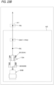
- Fig. 1 is an overall diagram illustrating a grass management system.
- the grass management system relates to a forming machine 10A that can form and discharge grass of a farm field and is a system that can make a setting for discharge of a formed material formed by the forming machine 10A.
- the forming machine 10A is a machine that harvests grass of a farm field and forms harvested farm products into a predetermined shape such as a roll shape and a rectangular shape (cube shape).
- the forming machine 10A is, for example, a round baler that forms grass into a roll shape, a whole crop, a hay baler that forms a rectangular shape, and the like.
- the forming machine 10A includes a traveling vehicle 20 and a forming device 30A.
- the traveling vehicle 20 is a tractor.
- the traveling vehicle 20 includes a vehicle body 21, a prime mover 22, and a transmission 23.
- the vehicle body 21 is provided with a traveling device 24.
- the traveling device 24 is a device having front wheels and rear wheels.
- the traveling device 24 may be a crawler device.
- the prime mover 22 is a diesel engine, an electric motor, or the like, and in this embodiment, the prime mover 22 includes a diesel engine.
- the transmission 23 can switch propulsive force of the traveling device 24 and can switch the traveling device 24 between forward and reverse movements.
- a connecting unit 25 including a three-point link mechanism or the like is provided in a rear portion of the vehicle body 21.
- the forming device 30A is detachable from the connecting unit 25. Connecting the forming device 30A to the connecting unit 25 allows the vehicle body 21 to pull the forming device 30A.
- the traveling vehicle 20 includes a power take-off (PTO) shaft driven by the power of the prime mover 22 or the like and can transmit the power of the PTO shaft to a work device.
- the traveling vehicle 20 includes a cabin 26 including a driver's seat therein.
- the traveling vehicle 20 includes an input output device 29 to which an external instrument 28, which is an electronic storage medium such as a USB memory and an SD card, is connected.
- the input output device 29 is connected to a control device 40 or the like and can write information (data) about the traveling vehicle 20 or the like into the external instrument 28 and acquire information about the external instrument 28.
- the forming device 30A includes a vehicle body 27 capable of moving (traveling) and a gathering unit 35 supported by the vehicle body 27 and configured to gather in grass.
- the gathering unit 35 is a device configured to gather in harvested grass on a farm field from a front side (traveling vehicle 20 side), and includes, for example, a casing 35a whose front side is open.
- the gathering unit 35 includes a rotating shaft 35b supported by the casing 35a or the like, and a guide tool 35c fixed to the rotating shaft 35b. Therefore, rotating the rotating shaft 35b allows the guide tool 35c to gather in grass on the farm field into the casing 35a.
- the gathering unit 35 of Fig. 2 is one example and is not limited to the above-described gathering unit 35.
- the forming device 30A includes an accommodation unit 36 and a discharge unit 37.
- the accommodation unit 36 is a case that accommodates the grass gathered in by the gathering unit 35.
- the discharge unit 37 is a part that discharges the grass to the farm field.
- the accommodation unit 36 includes a first case body 36a fixed to the vehicle body 27 and a second case body 36b that is vertically swingable with respect to the first case body 36a.
- the first case body 36a communicates with the gathering unit 35, and the grass gathered by the gathering unit 35 enters the first case body 36a.
- a state where the second case body 36b is close to the first case body 36a (state where the second case body 36b is swung downward) is a state where the grass is accommodated (accommodation state).
- a state where the second case body 36b is separated from the first case body 36a is a state where grass is discharged. That is, the discharge unit 37 is formed between the first case body 36a and the second case body 36b when the second case body 36b is swung upward with respect to the first case body 36a. Therefore, the accommodation unit 36 can accommodate the grass and the discharge unit 37 can discharge the grass.
- the accommodation unit 36 and the discharge unit 37 of Fig. 2 are one example and are not limited to the above-described accommodation unit 36 and the discharge unit 37.
- the state where the second case body 36b is swung downward with respect to the first case body 36a may be referred to as a closed state (gate closed state), whereas the state where the second case body 36b is swung upward with respect to the first case body 36a may be referred to as an open state (gate open state).
- the forming device 30A includes a forming unit 38.
- the forming unit 38 forms the grass gathered by the gathering unit 35. That is, the forming unit 38 is provided in the first case body 36a and the second case body 36b and forms the accommodated grass.
- the forming unit 38 is, for example, a device configured to form a roll-shaped formed material K1 with a plurality of rotating rollers.
- the forming unit 38 may be a chain device that forms grass into a roll with a chain, a belt device that forms grass into a roll with a belt, or a device of any other type. Therefore, the forming unit 38 can form the grass gathered by the accommodation unit 36 into a predetermined shape.
- the forming machine 10A includes a position detection module 90 (position detection module 90A).
- the position detection module 90A is installed on a top plate of the cabin 26 of the traveling vehicle 20. Note that although the position detection module 90A is installed on the top plate of the cabin 26, an installation place in the traveling vehicle 20 is not limited and may be another place. Alternatively, the position detection module 90A may be installed in the forming device 30A.
- the position detection module 90A is a position detection device that detects a position of the position detection module 90A (positioning information including latitude and longitude) with a satellite positioning system. That is, the position detection module 90A receives a signal transmitted from a positioning satellite (position of the positioning satellite, transmission time, correction information, and the like) and detects the position (for example, latitude and longitude) based on the received signal. Therefore, the position detection module 90A, which is provided in the forming machine 10, can detect the positions (machine positions at the time of forming work) at the time of work for the glass (at the time of traveling).
- the forming machine 10A includes the control device (control module) 40.
- the control device 40 is provided in the traveling vehicle 20.
- the control device 40 controls the traveling vehicle 20 based on operation signals in response to operation of operation tools (lever, switch, volume, and the like) installed around a driver's seat and detection signals and the like of various sensors (detection devices) mounted in the traveling vehicle 20.
- a sensor 41a that detects a crank position, a sensor 41b that detects a cam position, and a sensor 41c that detects a rotational speed (engine rotational speed) of the prime mover 22 are connected to the control device 40.
- the control device 41 controls the prime mover (engine) 22 by outputting a control signal obtained based on signals such as the crank position, the cam position, the engine rotational speed, and the like detected by the sensors 41a to 41c and the like to an injector, a common rail, a supply pump, and the like.
- control signals indicating fuel injection quantity, injection timing, and fuel injection rate are output to the injector.
- signals indicating fuel injection pressure and the like are output to the supply pump and the common rail.
- control of the prime mover (engine) 22 by the control device 40 is one example and is not restrictive.
- an elevating lever 42 configured to cause the connecting unit 25 to ascend and descend as an operation tool
- an electromagnetic control valve (not illustrated) configured to expand and contract an oil hydraulic cylinder that causes the connecting unit to operate are connected to the control device 40.
- the control device 40 outputs a control signal to the electromagnetic control valve to set an opening degree of the electromagnetic control valve and causes the connecting unit to ascend and descend by expanding and contracting the oil hydraulic cylinder.
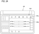
- the forming machine 10A includes a display device 48.
- the display device 48 is provided in the traveling vehicle 20.
- the display device 48 is provided near a driver's seat.
- the display device 48 is connected to the control device 40 and can exchange signals (data) with the control device 40.
- the display device 48 is provided with an input interface such as a touch panel and a switch and displays various information items regarding the forming machine 10A on a screen M2.
- the display device 48 displays on the screen M2 icons 48a indicating conditions of the traveling vehicle 20, and displays on the screen M2 a setting part 48b for setting the traveling vehicle 20 or the forming device 30A. Note that information displayed by the display device 48 is not limited to the example described above.
- the grass management system includes a prohibition setting module 50A configured to set prohibited positions at which discharge of the formed material K1 is prohibited.
- the prohibition setting module 50A is provided in a support device 55.
- the support device 55 is, for example, a device such as a personal computer owned by an administrator who manages grass. Note that the support device 55 may be a portable terminal such as a smartphone, a tablet, a personal digital assistant (PDA), or may be a server or the like.
- the support device 55 includes an arithmetic module 55a including a central processing unit (CPU) or the like, a display unit 55b, and a storage unit 55c including a nonvolatile memory or the like.
- the support device 55 includes a connection unit that can connect the external instrument 28.
- the display unit 55b is a device that performs various types of display and includes a liquid crystal panel or the like.
- the prohibition setting module 50A includes electric and electronic components provided in the support device 55, programs incorporated in the arithmetic module 55a (support device 55), and the like.
- the prohibition setting module 50A causes the display unit 55b of the support device 55 to display a setting screen M1.
- the setting screen M1 includes a setting part 101 for setting a farm field, and a farm field display part 103 that displays fields 102 indicating the farm field.
- identification information such as a farm field name corresponding to a farm field registered in advance by the administrator or the like in the support device 55, and a farm field code indicating the farm field.
- the farm field display part 103 the fields 102 corresponding to the identification information selected in the setting part 101 (farm field name, farm field code) are displayed.
- a position of the farm field (latitude, longitude) is associated with the fields 102.
- position information indicating the position of the farm field has been stored in advance in the storage unit 55c of the support device 55.
- the prohibition setting module 50A refers to the storage unit 55c and causes the position corresponding to the identification information indicated in the setting part 101 to be associated with the fields 102.
- the prohibition setting module 50A requests the administrator or the like to input information including latitude and longitude about an arbitrary point in the fields 102 (reference position). Based on the position (latitude, longitude) with respect to the reference position input by the administrator using an input interface (mouse, keyboard, or the like), the prohibition setting module 50A then assigns latitude and longitude to all points on the fields 102.
- the prohibited positions at which discharge of the formed material K1 is prohibited can be set in the fields 102.
- the prohibition setting module 50A sets the predetermined range A1 on the fields 102 as a prohibited area that prohibits discharge of the formed material K1.
- the prohibition setting module 50A sets, as the prohibited positions, all positions contained in the prohibited area A1 surrounding a diagonal line connecting the position P1 and the position P2.
- On the setting screen M1 as illustrated in Fig. 4B , by selecting a plurality of prohibited areas A1 and A2 on the fields 102 by using the input interface, all positions in the plurality of prohibited areas A1 and A2 can be set as the prohibited positions.
- the farm field display part 103 may display an image indicating the farm field in the fields 102 or a map of the farm field, or other information about the farm field may be superimposed and displayed.
- Fig. 5 is a diagram illustrating one example of the prohibited positions set by the prohibition setting module 50A, the positions of the farm field (positions of the fields 102), and the prohibited areas A1.
- the prohibited positions (prohibited positions illustrated in Fig. 5 ) set by the setting screen M1 (prohibition setting module 50A) are stored in the storage unit 55c as prohibition information.
- the prohibited positions and the identification information identifying the farm field may be stored in the storage unit 55c as the prohibition information.
- the forming machine 10A includes a prohibited position acquisition module.
- the prohibited position acquisition module is a device that acquires a prohibited position at which discharge of the formed material K1 is prohibited.
- the prohibited position acquisition module is the input output device 29 to which the external instrument 28 can be connected.
- the input output device 29 acquires the prohibition information including the prohibited positions stored in the external instrument 28.
- the acquired prohibition information is stored in the storage unit 40a provided in the control device 40.
- the control device (control module) 40 performs control based on a relationship between a discharge position (planned discharge position) to discharge the formed material K1 from the discharge unit 37, and the prohibited positions acquired by the prohibited position acquisition module (input output device 29).
- the forming machine 10A includes a discharge operation unit 43.
- the discharge operation unit 43 is an operation tool to operate discharge of the formed material K1 by the discharge unit 37, and is, for example, a switch that can be switched between ON and OFF.
- the discharge operation unit 43 is provided near the driver's seat and can be operated by the operator.
- a discharge instruction signal is input into the control device 40
- the discharge operation unit 43 is turned OFF, a discharge stop signal is input into the control device 40.
- the discharge operation unit 43 may be a switch that can be switched between ON and OFF displayed on the display device 48.
- the input output device 29 may be provided in the display device 48.
- the control device 40 sets a machine position P7 at which the discharge operation unit 43 is turned from OFF to ON as a discharge position DW1 for the formed material K1.
- the control device 40 may set a position several meters to several tens of meters from the machine position (machine position at the time of switching) P7 at the time when the discharge operation unit 43 is switched from OFF to ON as the discharge position DW1.
- a travel distance of the forming machine 10A from when the discharge operation unit 43 is switched from OFF to ON until the formed material K1 is discharged to the farm field may be set in advance, and a position obtained by adding the preset travel distance to the machine position at the time of switching may be set as the discharge position DW1.
- the setting of the discharge position DW1 described above is one example and is not limited thereto.
- the control device 40 refers to the prohibition information stored in the storage unit 40a and determines whether or not the discharge position DW1 set by the discharge operation unit 43 is set at the prohibited position. That is, the control device 40 determines whether or not the discharge position DW1 and the prohibited position agree with each other.
- the control device 40 permits discharge of the formed material K1, and for example, by outputting a control signal to a switching valve or the like that expands and contracts the oil hydraulic cylinder connected to the second case body 36b, the control device 40 expands the oil hydraulic cylinder and makes the forming device 30A in a gate open state.
- the control device 40 does not permit discharge of the formed material K1, maintains the oil hydraulic cylinder in a contracted state, and holds the forming device 30A in a gate closed state. That is, even if the operator switches the discharge operation unit 43 from the OFF state to the ON state, the control device 40 does not shift the forming device 30A to a gate open state.
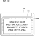
- the control device 40 outputs, to the display device 48, a control signal indicating that the discharge position agrees with the prohibited position.
- the display device 48 performs display indicating that the discharge position agrees with the prohibited position. For example, as illustrated in Fig. 3B , in a situation where information about the forming machine 10A is displayed on the screen M2, the display device 48 displays a pop-up screen M3 that pops up on the screen M2 displaying the information, and the display device 48 displays an indication that the discharge position and the prohibited position agree with each other on the pop screen M3.
- the discharge operation unit 43 may be a switch that can be switched between ON and OFF displayed on the display device 48.
- the input output device 29 may be provided in the display device 48.
- Fig. 7 is an overall diagram illustrating a grass management system in a second embodiment.
- the grass management system includes a prohibition setting module 50B configured to set prohibited positions.
- the prohibition setting module 50B sets the prohibited positions based on information when a work machine travels.
- the work machine is a machine that performs work related to grass.
- the work machine is, for example, a grass harvesting machine 10B, a dispersion machine 10C, a grass raking machine 10D, and the like.
- a grass harvesting machine 10B a dispersion machine 10C
- a grass raking machine 10D a grass raking machine 10D
- the grass harvesting machine 10B is a machine configured to harvest grass and includes a traveling vehicle 20 and a harvesting device 30B connected to the traveling vehicle 20.
- the harvesting device 30B includes a connecting frame 62 connected to a connecting unit 25 of the traveling vehicle 20, and a harvesting unit 63 connected to the connecting frame 62.
- the harvesting unit 63 includes a gathering unit 65 configured to gather in grass to harvest and a plurality of cutting units 66 configured to cut the grass gathered by the gathering unit 65.
- Fig. 8 illustrates one cutting unit 66 among the plurality of cutting units 66 included in the harvesting device 30B.
- the cutting unit 66 includes a plurality of rotating shafts 67 and a plurality of cutters 68 attached to the rotating shafts 67.
- the power of the PTO shaft is transmitted to the rotating shafts 67 via a driving shaft supported by the connecting frame 62, thereby rotating the rotating shafts 67.
- the cutters 68 are disk-shaped cutters, and the adjacently arranged cutters 68 rotate in response to the rotation of the rotating shafts 67, thereby cutting grass. That is, the rotating shafts 67 rotate the cutters 68, which harvest grass, and the harvested grass is discharged outside.
- the harvesting device 30B is not limited to the above-described configuration and is required at least to harvest grass.
- the harvesting device 30B may be a hammer knife type configured to harvest grass with knife-shaped cutters 68, or any other type.
- the dispersion machine 10C is a machine configured to disperse the harvested grass and includes the traveling vehicle 20 and a dispersion device 30C connected to the traveling vehicle 20.
- the dispersion device 30C includes a connecting frame 72 connected to the connecting unit 25 of a traveling device 20, and dispersion units 73 connected to the connecting frame 72. Note that Fig. 9 illustrates an example in which two dispersion units 73 are connected to the connecting frame 72.
- the dispersion units 73 each include a body 74 connected to the connecting frame 72, a rotating shaft 75 rotatably supported by the body 74, a plurality of arms (tine arms) 76 connected to the rotating shaft 75, and dispersion tools (tines) 77 connected to the plurality of arms 76.
- the tine 77 is, for example, a member with a distal end divided into two branches.
- the power of the PTO shaft is transmitted to the rotating shaft 75 via a driving shaft supported by the connecting frame 72, thereby rotating the rotating shaft 75.
- the arms 76 rotate, and the dispersion tools 77 disperse grass.
- the rotation of the rotating shaft 75 causes the dispersion tools 77 to rotate, and the dispersion tools 77 disperse grass.
- the dispersion device 30C is not limited to the above-described configuration and is required at least to disperse grass.
- one dispersion unit 73, or three or more dispersion units 73 may be provided.
- the dispersion unit 73 may be a rotary type in which a rotor with the dispersion tools 77 rotates around a longitudinal axis, may be a belt/chain type in which the plurality of dispersion tools 77 is attached to a rotating belt or chain, or may be any other type.
- the grass raking machine 10D is a machine configured to rake grass and includes the traveling vehicle 20 and a grass raking device 30D connected to the traveling vehicle 20.
- the grass raking device 30D includes a connecting frame 82 connected to the connecting unit 25 of the traveling vehicle 20, and grass raking units 83 connected to the connecting frame 82.
- Fig. 10 illustrates an example in which two grass raking units 83 are connected to the connecting frame 82.
- the grass raking units 83 each include a body 84 connected to the connecting frame 82, a rotating shaft 85 rotatably supported by the body 84, a plurality of arms (tine arms) 86 connected to the rotating shaft 85, and grass raking tools (tines) 87 connected to the plurality of arms 86.
- an interval of the grass raking tools 87 in the grass raking device 30D is shorter than in the dispersion tools 77 of the dispersion device 30C.
- the tine 87 is, for example, a member with a distal end divided into two branches.
- the power of the PTO shaft is transmitted to the rotating shaft 85 via a driving shaft supported by the connecting frame 82, thereby rotating the rotating shaft 85.
- the rotating shaft 85 rotates, the arms 86 rotate, and the grass raking tools 87 rake grass. That is, the rotation of the rotating shaft 85 causes the grass raking tools 87 to rotate, and the grass raking tools 87 rake grass.
- the grass raking device 30D is not limited to the above-described configuration and is required at least to rake grass.
- one grass raking unit 83, or three or more grass raking units 83 may be provided.
- the grass raking unit 83 may be a rotary type in which a rotor with the grass raking tools 87 rotates around a longitudinal axis, may be a belt/chain type in which the plurality of grass raking tools 87 is attached to a rotating belt or chain, or may be any other type.
- the traveling vehicle of the forming machine 10A may be referred to as “20A”
- the traveling vehicle of the grass harvesting machine 10B may be referred to as “traveling vehicle 20B”
- the traveling vehicle of the dispersion machine 10C may be referred to as “traveling vehicle 20C”
- the traveling vehicle of the grass raking machine 10D may be referred to as “traveling vehicle 20D.”
- the work machines (grass harvesting machine 10B, dispersion machine 10C, grass raking machine 10D) include position detection modules 90 (position detection module 90B, position detection module 90C, position detection module 90D).
- the position detection modules 90B, 90C, and 90D are installed on a top plate of a cabin 26 of the traveling vehicles 20 (traveling vehicles 20B, 20C, 20D). Note that although the position detection modules 90B, 90C, and 90D are installed on the top plate of the cabin 26, an installation place in the traveling vehicle 20 is not limited and may be any other place.
- the position detection modules 90B, 90C, and 90D are position detection devices configured to detect positions of the position detection modules 90B, 90C, and 90D (positioning information including latitude and longitude) with a satellite positioning system. That is, the position detection modules 90B, 90C, and 90D each receive a signal transmitted from a positioning satellite (position of the positioning satellite, transmission time, correction information, and the like) and detect the position (for example, latitude and longitude) based on the received signal.
- providing the position detection modules 90B, 90C, and 90D in the grass harvesting machine 10B, the dispersion machine 10C, and the grass raking machine 10D respectively allows individual detection of positions at the time of work (at the time of traveling) related to grass (machine positions at the time of harvesting work, machine positions at the time of dispersion work, machine positions at the time of grass raking work).
- the machine positions at the time of harvesting work are stored in the storage unit 40a provided in the traveling vehicle 20B.
- the machine positions at the time of dispersion work are stored in the storage unit 40a provided in the traveling vehicle 20C.
- the machine positions at the time of grass raking work are stored in the storage unit 40a provided in the traveling vehicle 20D.
- the work machines (forming machine 10A, grass harvesting machine 10B, dispersion machine 10C, grass raking machine 10D) include operation units 91 (operation unit 91A, operation unit 91B, operation unit 91C, operation unit 91D).
- the operation units 91A, 91B, 91C, and 91D are each a switch that instructs prohibition of discharge of a formed material K1.
- the operation units 91A, 91B, 91C, and 91D are each a switch that can be switched between ON and OFF, and connected to the control device 40.
- the operation units 91A, 91B, 91C, and 91D each output, to the control device 40, a prohibition signal instructing prohibition of discharge, and when the switch is OFF, the operation units 91A, 91B, 91C, and 91D each output, to the control device 40, a permission signal permitting discharge.
- the operation units 91A, 91B, 91C, and 91D are provided near driver's seats of the traveling vehicles 20A, 20B, 20C, and 20D, respectively and can be operated by an operator.
- the prohibited position can be set.
- the prohibition setting module 50B sets the prohibited positions based on information when the work machine travels (machine positions) and operations of the operation units 91A, 91B, 91C, and 91D.
- the prohibition setting module 50B includes electric and electronic components provided in the control device 40, programs incorporated in the control device 40, and the like.
- the prohibition setting module 50B sets, as a prohibited area, the machine positions while the operation unit 91B is ON at the time of harvesting work, that is, a range from the machine position PB3 to the machine position PB7 in Fig. 11 . Meanwhile, in a state where the operation unit 91B is maintained OFF (state where the control device 40 has acquired the permission signal), the prohibition setting module 50B does not set the machine positions at the time of harvesting work PBn as the prohibited positions.
- the prohibition setting module 50B sets, as the prohibited positions, the machine positions PCn while the operation unit 91C is ON at the time of dispersion work.
- the prohibition setting module 50B does not set, as the prohibited positions, the machine positions PCn while the operation unit 91C is OFF.
- the prohibition setting module 50B sets, as the prohibited positions, the machine positions PDn while the operation unit 91D is ON at the time of grass raking work.
- the prohibition setting module 50B does not set, as the prohibited positions, the machine positions PDn while the operation unit 91D is OFF.
- This embodiment allows setting the prohibited positions in all work in the harvesting work, the dispersion work, and the grass raking work, but of course is not limited thereto. It is required at least to set the prohibited positions in any of the harvesting work, the dispersion work, and the grass raking work.
- the harvesting work, the dispersion work, and the grass raking work have been exemplified as the work related to grass, but the work related to grass is not limited thereto and may be performed at the time of fertilization work or any other work.
- the prohibited positions can be set by providing a fertilizing machine with the position detection module 90, the operation unit 91, and the prohibition setting module 50B.
- prohibited positions may also be set at the time of forming work by the forming machine 10A.
- the prohibited positions can be set by turning ON the operation unit 91A.
- the prohibited positions are stored as prohibition information in the storage unit 40a of the control device 40 provided in each traveling vehicle 20.
- the prohibition information including the prohibited positions can be transferred from the storage unit 40a to the external instrument 28 by connecting the external instrument 28 to the input output device 29 provided in the traveling vehicle 20. Also, by connecting the external instrument 28 to the support device 55, the prohibition information stored in the external instrument 28 can be transferred to the storage unit 55c of the support device 55.
- the prohibition setting module 50B may be provided in the support device 55.
- the prohibition setting module 50B includes a program and the like incorporated in an arithmetic module 55a (support device 55) and the like.
- the control device 40 associates discharge setting information indicating ON/OFF of the operation unit 91 (prohibition signal, permission signal) with the machine positions detected by the position detection module 90, and stores the associated information in the storage unit 40a as the prohibition information. Also, when the external instrument 28 is connected to the input output device 29 of the traveling vehicle 20, the prohibition information (discharge setting information and machine positions) stored in the storage unit 40a is transferred to the external instrument 28. When the external instrument 28 is connected to the support device 55, the prohibition information (discharge setting information and machine positions) is transferred to the support device 55.
- the prohibition setting module 50B of the support device 55 sets the prohibited positions based on the discharge setting information and the machine positions.
- a method of setting the prohibited positions by the prohibition setting module 50B is similar to the above-described method.
- Fig. 12 is an overall diagram illustrating a grass management system in a third embodiment.
- the grass management system includes a prohibition setting module 50C configured to set prohibited positions.
- the prohibition setting module 50C sets the prohibited positions based on information when a work machine travels.
- the work machines (forming machine 10A, grass harvesting machine 10B, dispersion machine 10C, grass raking machine 10D) include inclination detection modules 92 (inclination detection module 92A, inclination detection module 92B, inclination detection module 92C, inclination detection module 92D).
- the inclination detection modules 92 are inertial devices that can detect an inclination when the work machines travel.
- the inclination detection modules 92 are sensors that can detect acceleration, angular velocity, and the like, and are acceleration sensors, gyro sensors, or the like.
- the inclination detection modules 92A, 92B, 92C, and 92D are provided in traveling vehicles 20A, 20B, 20C, and 20D, respectively, and are connected to control devices 40.
- the control devices 40 can acquire the acceleration, the angular velocity, and the like detected by the inclination detection modules 92A, 92B, 92C, and 92D, and can detect the inclinations of the traveling vehicles 20A, 20B, 20C, and 20D respectively from the acquired acceleration and the angular velocity.
- the inclination detection modules 92A, 92B, 92C, and 92D may be provided in a forming device 30A, a harvesting device 30B, a dispersion device 30C, and a grass raking device 30D, respectively.
- the control devices 40 may obtain the respective inclinations of the forming device 30A, the harvesting device 30B, the dispersion device 30C, and the grass raking device 30D.
- the prohibition setting module 50C sets the prohibited positions based on information when the work machine travels (machine positions, inclination).
- the prohibition setting module 50C includes electric and electronic components provided in the control device 40, programs incorporated in the control device 40, and the like.
- a position detection module 90B detects machine positions at the time of harvesting work PBn.
- the prohibition setting module 50C of the traveling vehicle 20B sequentially determines the inclination ⁇ of a running direction (traveling direction) of the traveling vehicle 20B (inclination ⁇ of the traveling vehicle with respect to a horizontal direction) by using acceleration, angular velocity, and the like detected by the inclination detection module 92B.
- the prohibition setting module 50C holds the machine position PBn when the inclination ⁇ of the traveling vehicle 20B becomes equal to or greater than the threshold. Furthermore, at the time of harvesting work, when the inclination ⁇ at the machine position PBn changes from equal to or greater than the threshold to less than the threshold, the prohibition setting module 50C holds the machine position PBn when the inclination ⁇ of the traveling vehicle 20B changes to less than the threshold. For example, as illustrated in Fig.
- the prohibition setting module 50C sets the machine positions from the machine position PB3 to the machine position PB12 as the prohibited positions. Meanwhile, when the inclination ⁇ of the traveling vehicle 20B is less than the threshold, the machine positions are not set as the prohibited positions.
- a position detection module 90C detects the machine positions at the time of dispersion work PCn.
- the prohibition setting module 50C of the traveling vehicle 20C sequentially determines the inclination ⁇ of a running direction of the traveling vehicle 20C by using acceleration, angular velocity, and the like detected by the inclination detection module 92C.
- the prohibition setting module 50C sets, as the prohibited positions, the machine positions PCn when the inclination ⁇ of the traveling vehicle 20C becomes equal to or greater than the threshold, and does not set the machine positions as the prohibited positions when the inclination ⁇ of the traveling vehicle 20C is less than the threshold.
- the position detection module 90C detects the machine positions at the time of dispersion work PDn.
- the prohibition setting module 50C of the traveling vehicle 20D sequentially determines the inclination ⁇ of a running direction of the traveling vehicle 20D by using acceleration, angular velocity, and the like detected by the inclination detection module 92D.
- the prohibition setting module 50C sets, as the prohibited positions, the machine positions PDn when the inclination ⁇ of the traveling vehicle 20D becomes equal to or greater than the threshold, and does not set the machine positions as the prohibited positions when the inclination ⁇ of the traveling vehicle 20D is less than the threshold.
- the threshold (inclination determination value) is set at an angle at which, when a formed material K1 is discharged, at least the roll-shaped formed material K1 does not roll and move. It is preferable to set the angle at which the formed material K1 does not roll and move by past actual results, simulation, or the like.
- the harvesting work, the dispersion work, and the grass raking work have been exemplified as the work related to grass, but the work related to grass is not limited thereto and may be performed at the time of fertilization work or any other work.
- the prohibited positions can be set by providing a fertilizing machine with the position detection module 90, the inclination detection module 92, and the prohibition setting module 50C.
- prohibited positions may also be set at the time of forming work by the forming machine 10A.
- the position detection module 90A detects the machine positions at the time of forming work PAn.
- the prohibition setting module 50C sequentially determines the inclination ⁇ of a running direction of the traveling vehicle 20A by using acceleration, angular velocity, and the like detected by the inclination detection module 92A.
- the prohibition setting module 50C sets, as the prohibited positions, the machine positions PAn when the inclination ⁇ of the traveling vehicle 20A becomes equal to or greater than the threshold, and does not set machine positions as the prohibited positions when the inclination ⁇ of the traveling vehicle 20A is less than the threshold.
- the prohibited positions are stored in the storage unit 40a of the control device 40 provided in each traveling vehicle 20.
- the prohibited positions stored in the storage unit 40a can be transferred to the support device 55 via an external instrument 28.
- the prohibition setting module 50C may be provided in the support device 55.
- the prohibition setting module 50C includes a program or the like incorporated in an arithmetic module 55a (support device 55) and the like.
- the control device 40 associates inclination information on the inclination of the traveling vehicle 20 [detection information detected by the inclination detection module 92 (acceleration, angular velocity), or inclination ⁇ of the traveling vehicle 20 determined from the acceleration, angular velocity, or the like] with the machine positions detected by the position detection module 90, and then the control device 40 stores the associated information in the storage unit 40a.
- the control device 40 transfers the inclination information and the machine positions stored in the storage unit 40a to the external instrument 28.
- the inclination information and the machine positions are transferred to the support device 55.
- the prohibition setting module 50C of the support device 55 sets the prohibited positions based on the inclination information and the machine positions.
- a method of setting the prohibited positions by the prohibition setting module 50C is similar to the above-described method.
- Fig. 14 is an overall diagram illustrating a grass management system in a fourth embodiment.
- the grass management system includes a prohibition setting module 50D configured to set prohibited positions.
- the grass management system includes a topographical information detection module.
- the topographical information detection module is a device configured to acquire topographical information of a farm field.
- the topographical information detection module acquires height information of the farm field detected at the time of forming work by a forming machine 10A as the topographical information.
- the topographical information detection module is a position detection module 90A provided in the forming machine 10A.
- the position detection module 90A detects not only positions (latitude, longitude) but also height (height information) in a vertical direction (height direction) on the basis of a signal transmitted from a positioning satellite at the time of forming work.
- the latitude and longitude detected by the position detection module 90A are two-dimensional information (X-axis direction and Y-axis direction), and the height information is three-dimensional information in the vertical direction (Z-axis direction) of the farm field, which is detected by the position detection module 90A and can be used as the topographical information of the farm field.
- ups and downs of a farm field that is, a topographical state of the farm field can be detected by a change in a height (change in the Z-axis direction) at the time of forming work.
- the topographical information detection module may be a device configured to acquire the height information of the farm field detected at the time of harvesting work by a harvesting machine 10B as the topographical information.
- the topographical information detection module is a position detection module 90B provided in the harvesting machine 10B.
- the topographical information detection module may be a device configured to acquire the height information of the farm field detected at the time of dispersion work by a dispersion machine 10C as the topographical information.
- the topographical information detection module is a position detection module 90C provided in the dispersion machine 10C.
- the topographical information detection module may be a device configured to acquire the height information of the farm field detected at the time of grass raking work by a grass raking machine 10D as the topographical information.
- the topographical information detection module is a position detection module 90D provided in the grass raking machine 10D.
- the topographical information detection module is required at least to be a device that acquires the topographical information of the farm field.
- the topographical information detection module is not limited to the position detection module 90A, the position detection module 90B, the position detection module 90C, or the position detection module 90D.
- an imaging device such as a camera (topographical information detection module) may be provided in a multicopter, and an image obtained by the imaging device may be used as the topographical information.
- the topographical information detection module including the position detection module 90 capable of detecting height may be provided in a fertilizing machine that fertilizes in the farm field, a spraying machine that sprays a medicine, or the like.
- the topographical information can be transferred to a support device 55 via an external instrument 28.
- the grass management system includes a prohibition setting module 55D and a map creation module 93.
- the prohibition setting module 55D and the map creation module 93 each include a program or the like incorporated in an arithmetic module 55a (support device 55) and the like.
- the map creation module 93 creates a three-dimensional inclination map (farm field map) 110 indicating ups and downs of the farm field based on the topographical information.
- the prohibition setting module 55D sets the positions of the farm field at which the inclination indicated in the inclination map 110 is equal to or greater than a threshold as the prohibited positions. For example, when the inclination angles in the mesh parts Q1 to Q110 are equal to or greater than the threshold, the prohibition setting module 55D sets the positions of the farm field corresponding to the mesh parts Q1 to Q110 as the prohibited positions. In other words, the prohibition setting module 55D sets all the positions included in a prohibited area A3 including the mesh parts Q1 to Q110 as the prohibited positions. Meanwhile, for example, when the inclination angles in the mesh parts Q111 to Q143 are less than the threshold, the prohibition setting module 55D does not set the positions of the farm field corresponding to the mesh parts Q111 to Q143 as the prohibited positions.
- the inclination map (farm field map) 110 created by the map creation module 93 may be displayed on a display unit 55b of the support device 55.
- the support device 55 can create the inclination map 110 of the farm field based on the topographical information, and the prohibition setting module 50D can set the prohibited positions when the inclination angles of the farm field indicated in the inclination map 110 are equal to or greater than the threshold.
- Fig. 16 is an overall diagram illustrating a grass management system in a fifth embodiment.
- the grass management system in the fifth embodiment is a system configured to display an inclination map of a farm field on a setting screen M1 for setting prohibited positions.
- the grass management system includes a prohibition setting module 50A, a topographical information detection module, and a map creation module 93.
- the topographical information detection module and the map creation module 93 are similar to those in the fourth embodiment.
- Fig. 17 is one example in which an inclination map 110 created by the map creation module 93 is displayed on the setting screen M1.
- the prohibition setting module 50A causes a display unit 55b of the support device 55 to display the setting screen M1 including a setting part 101 and a farm field display part 103.
- the three-dimensional inclination map 110 created by the map creation module 93 and three-dimensional fields 102 corresponding to the inclination map 110 are superimposed and displayed. That is, the fields 102 of the farm field set in the setting part 101 and the inclination map 110 set in the setting part 101 are superimposed and displayed on the farm field display part 103. Therefore, the administrator or the like can determine a degree to which the farm field is inclined with respect to the fields 102 from a relationship between the fields 102 and the inclination map 110.
- the administrator can set the prohibited positions by selecting a predetermined range of the fields 102 with an input interface while looking at the relationship between the fields 102 and the inclination map 110.
- Fig. 18 is an overall diagram illustrating a grass management system in a sixth embodiment.
- the grass management system in the sixth embodiment is a system configured to set prohibited positions based on a boundary of a farm field obtained from topographical information.
- the grass management system includes a prohibition setting module 50E and a topographical information detection module.
- the prohibition setting module 50E includes a program or the like incorporated in an arithmetic module 55a (support device 55) and the like.
- the topographical information detection module is similar to that in the fourth embodiment.
- the prohibition setting module 50E creates a farm field map 111 including a boundary line (contour line) E1 of the farm field.
- the prohibition setting module 50E displays the farm field map 111 on a display unit 55b of the support device 55.
- the prohibition setting module 50E sets, as the prohibited positions, at least one of prohibited areas A1n formed between the boundary lines E1n of the farm field and imaginary lines E2n obtained by shifting the boundary lines En inward of the farm field by a predetermined distance D1.
- the prohibition setting module 50E sets, as the prohibited positions, for example, positions corresponding to the prohibited area A11 formed between the boundary line E11 and the imaginary line E21 obtained by shifting the boundary line E11 inward of the farm field by the predetermined distance D1.
- the prohibition setting module 50E applies the boundary line E1n adjacent to the road or the boundary line E1n adjacent to the house as the boundary line E1n for setting the prohibited positions.
- the boundary line E1n for setting the prohibited positions may be selected by using an input interface, and the boundary lines E1n adjacent to the road or the house may be extracted from the topographical information of the farm field. In this way, when the farm field is adjacent to a road or a house, it is possible to easily set the prohibited positions from the topographical information of the farm field.
- Fig. 20 is a block diagram illustrating a forming machine in a seventh embodiment.
- the forming machine illustrated in the seventh embodiment is required at least to be a forming machine configured to acquire prohibited positions, and a method of setting the prohibited positions is not limited to the above-described method and may be any method. Note that methods of setting the prohibited positions described in the first to sixth embodiments described above may be applied to the forming machine of the seventh embodiment, or some configurations of the first to sixth embodiments described above may be applied.
- the forming machine 10A includes a prohibited position acquisition module, a discharge operation unit 43, and a traveling state detection module 44.
- the prohibited position acquisition module and the discharge operation unit 43 are similar to those in the first embodiment.
- the traveling state detection module 44 is a device configured to detect a traveling state of the forming machine 10A, and is, for example, a vehicle speed sensor that detects a traveling speed, a clutch detection sensor that detects a transmission gear of a transmission 23, a brake detection sensor that detects whether braking is applied or not.
- the traveling state detection module 44 is required at least to be a device capable of detecting the traveling state of the forming machine 10A, and is not limited to the vehicle speed sensor, the clutch sensor, the brake detection sensor, and the like.
- a control device 40 determines whether or not the forming machine 10A is at a standstill based on the traveling state detection module 44. Also, when the forming machine 10A is at a standstill, the control device 40 sets a discharge position DW1 of a formed material K1 at a current machine position detected by a position detection module 90A. The control device 40 refers to the discharge position (machine position) DW1 and prohibition information stored in a storage unit 40a and determines whether or not the discharge position DW1 set by the discharge operation unit 43 is set at the prohibited position.
- the control device 40 permits discharge of the formed material K1 and makes a forming device 30A in a gate open state.
- the control device 40 does not permit discharge of the formed material K1 and holds the forming device 30A in a gate closed state.
- the forming machine 10A may include a forming state detection module 45.
- the forming state detection module 45 is a device configured to detect a forming state of grass formed by a forming unit 38.
- the forming state detection module 45 is, for example, a sensor that detects a roll diameter of the formed material K1 formed by the forming unit 38.
- the control device 40 causes a display device 48 to display guidance indicating that the roll diameter is equal to or greater than the threshold, that is, an accommodation unit 36 is almost full of the formed material K1 (timing of discharging the formed material K1 is approaching).
- the operator decelerates and stops the forming machine 10A according to the guidance displayed on the display device 48, and then switches the discharge operation unit 43 from OFF to ON.
- the control device 40 determines whether or not the discharge position (machine position) DW1 is set at the prohibited position, when the discharge position DW1 does not agree with the prohibited position, the control device 40 discharges the formed material K1, and when the discharge position DW1 agrees with the prohibited position, the control device 40 does not discharge the formed material K1.
- the forming machine 10A may include a cancel operation unit 46.
- the cancel operation unit 46 is an operating tool for giving instructions to cancel the prohibited positions.
- the cancel operation unit 46 is, for example, a switch that can be switched between ON and OFF.
- the cancel operation unit 46 is provided near a driver's seat and can be operated by the operator. When the cancel operation unit 46 is turned ON, a cancel instruction signal is input into the control device 40, and when the cancel operation unit 46 is turned OFF, the cancel instruction signal is not input into the control device 40.
- the cancel operation unit 46 may be a switch that can be switched between ON and OFF displayed on the display device 48.
- the display device 48 performs a display indicating that the discharge position and the prohibited position agree with each other by the control of the control device 40.
- the display device 48 performs a display indicating that the prohibited positions can be canceled by the cancel operation unit 46.
- the control device 40 permits the cancel operation unit 46 to cancel the prohibited positions and makes the forming device 30A in a gate open state.
- the control device 40 does not permit discharge of the formed material K1 but holds the forming device 30A in a gate closed state.
- Fig. 21 is a control block diagram of a forming machine in an eighth embodiment.
- the forming machine illustrated in the eighth embodiment is required at least to be a forming machine configured to acquire prohibited positions, and a method of setting the prohibited positions is not limited to the above-described method and may be any method. Note that methods of setting prohibited positions described in the first to sixth embodiments described above may be applied to the forming machine of the eighth embodiment, or some configurations of the first to seventh embodiments described above may be applied.
- the forming machine 10A in the eighth embodiment is a forming machine that automatically discharges a formed material K1 without operation of a discharge operation unit 43.
- the forming machine 10A includes a prohibited position acquisition module and a forming state detection module 45.
- the prohibited position acquisition module and the forming state detection module 45 are similar to those in the seventh embodiment.
- a control device 40 automatically decelerates the forming machine 10A. Also, after the forming machine 10A decelerates, the control device 40 moves to a preparation stage of a discharge operation by an accommodation unit 36 (discharge unit 37), sets a machine position at the time of entering the preparation stage as a discharge position DW1, and determines whether or not the discharge position DW1 and the prohibited position agree with each other. When the discharge position DW1 and the prohibited position agree with each other, the control device 40 does not perform the discharge operation.
- the control device 40 performs the discharge operation.
- the machine position at the time of moving to the preparation stage of the discharge operation by the accommodation unit 36 (discharge unit 37) after deceleration of the forming machine 10A has been set as the discharge position DW1; however, instead of this, a position several meters to several tens of meters beyond the machine position in the preparation stage may be set as the discharge position DW1.
- a travel distance of the forming machine 10A from the preparation stage until the formed material K1 is discharged to a farm field may be set in advance, and a position obtained by adding the preset travel distance to the machine position in the preparation stage may be set as the discharge position DW1.
- the setting of the discharge position DW1 described above is one example and is not limited thereto.
- Fig. 22 is a control block diagram of a forming machine in a ninth embodiment.
- the forming machine illustrated in the ninth embodiment is required at least to be a forming machine configured to acquire prohibited positions, and a method of setting the prohibited positions is not limited to the above-described method and may be any method. Note that methods of setting prohibited positions described in the above first to sixth embodiments may be applied to the forming machine of the ninth embodiment, or some configurations of the first to eighth embodiments described above may be applied.
- the forming machine 10A includes a prohibited position acquisition module, a forming state detection module 45, and a discharge prediction module 47.
- the prohibited position acquisition module and the forming state detection module 45 are similar to those in the embodiments described above.
- the discharge prediction module 47 includes electric and electronic components provided in a control device 40, programs incorporated in the control device 40, and the like.
- the discharge prediction module 47 predicts a discharge position DW1 before discharging a formed material K1 based on a position detected by a position detection module 90A (machine position) and a forming state detected by the forming state detection module 45. After starting harvest (collection) of grass, the discharge prediction module 47 monitors a roll diameter detected by the forming state detection module 45 and estimates a position where the roll diameter reaches a threshold (discharge recommended diameter) from an increasing tendency of the roll diameter.
- the discharge prediction module 47 adds a travel distance from the point where reaching the discharge recommended diameter until when the forming machine 10A stops to the position estimated (estimated position), and then the discharge prediction module 47 sets the position obtained by the addition (estimated position + travel distance) as the discharge position DW1.
- the travel distance from the point where reaching the discharge recommended diameter until when the forming machine 10A stops may be stored in advance in the control device 40 or may be calculated by the discharge prediction module 47 from past actual results and the like.
- the discharge prediction module 47 After starting harvest (collection) of grass, the discharge prediction module 47 has monitored the roll diameter to determine the estimated position from the increasing tendency of the roll diameter; however, the discharge prediction module 47 may determine the estimated position by using the increasing tendency of the roll diameter in the past. Also, the method of estimating the discharge position DW1 by the discharge prediction module 47 is not limited to the method described above.
- the control device 40 causes the discharge unit 37 to perform discharge at a position that is different from the discharge position DW1 predicted by the discharge prediction module 47 and does not agree with the prohibited position.
- the discharge position DW1 obtained by the discharge prediction module 47 it is determined whether or not the discharge position DW1 obtained by the discharge prediction module 47 agrees with the prohibited position. As illustrated in Fig.
- the control device 40 controls the forming machine 10A (discharge unit 37) such that the forming machine 10A sets a position before a prohibited area A4 including the prohibited position PA1, for example, a position P4 as the discharge position, and discharges the formed material K1 at the discharge position P4.
- the control device 40 controls the forming machine 10A (discharge unit 37) such that the forming machine 10A sets a position beyond the prohibited area A5, for example, a position P6 as the discharge position, and discharges the formed material K1 at the discharge position P6.
- the forming machine 10A described above has a structure in which the formed material K1 in an accommodation room 36 is discharged directly to a farm field when an accommodation unit 36 is set in a gate open state; however, the forming machine 10A may be a forming machine including a holding mechanism (discharge unit) that temporarily holds the formed material K1 discharged to the outside from the accommodation room 36 and discharges the held formed material K1 under the farm field.
- a holding mechanism discharge unit
- an input output device (prohibited position acquisition module) 29 may be a communication device that can be connected to a support device 55 or the like by wireless communication or the like.
- the communication device is a device that performs wireless communication by short-distance wireless communication such as WiFi (trademark) and BLE, a cellular phone communication network, a data communication network, a cellular phone communication network, or the like. This allows information such as the prohibited position set on the work machine side to be transmitted to the support device 55 and allows the work machine to receive information such as the prohibited position set on the support device 55 side.
Landscapes
- Life Sciences & Earth Sciences (AREA)
- Environmental Sciences (AREA)
- Engineering & Computer Science (AREA)
- Mechanical Engineering (AREA)
- Soil Sciences (AREA)
- Harvester Elements (AREA)
Claims (13)
- Grasverwaltungssystem, das dazu ausgelegt ist, eine Formungsmaschine (10A) zum Einsammeln von Gras auf einem Anbaufeld und dann Formen und Auswerfen des gesammelten Grases in das Anbaufeld zu steuern, wobei Arbeit bezüglich Grases, die von einer Arbeitsmaschine (10B, 10C, 10D) vor der Formarbeit durchgeführt worden ist, von der Formmaschine (10A) durchgeführt wird, wobei das Grasverwaltungssystem Folgendes umfasst:- ein Verbotseinstellungsmodul (50A; 50B), das dazu ausgelegt ist, eine verbotene Position einzustellen, bei der Auswurf eines geformten Materials verboten ist, wobei das Verbotseinstellungsmodul (50A; 50B) dazu ausgelegt ist, die verbotene Position basierend auf Informationen einzustellen, wann sich die Arbeitsmaschine fortbewegt, wobei Arbeit bezüglich Grases von der Arbeitsmaschine (10B, 10C, 10D) durchgeführt wird, bevor die Formarbeit von der Formmaschine (10A) durchgeführt wird;- ein Verbotspositionsbeschaffungsmodul (29), das dazu ausgelegt ist, die eingestellte verbotene Position zu beschaffen; und- ein Steuerungsmodul (40), das dazu ausgelegt ist, die Formmaschine basierend auf einer Beziehung zwischen einer Auswurfposition, bei der geplant ist, das geformte Material auszuwerfen, und der verbotenen Position zu steuern.
- Formmaschine, die das Grasverwaltungssystem nach Anspruch 1 aufweist, wobei die Formmaschine (10A) Folgendes umfasst:- eine Sammeleinheit (35), die dazu ausgelegt ist, Gras auf einem Anbaufeld einzusammeln;- eine Formeinheit (38), die dazu ausgelegt ist, das von der Sammeleinheit (35) gesammelte Gras zu formen; und- eine Auswurfeinheit (37), die dazu ausgelegt ist, das von der Formeinheit (38) geformte Gras in das Anbaufeld auszuwerfen;wobei die Formmaschine (10A) weiter Folgendes umfasst:- das Verbotspositionsbeschaffungsmodul (29); und- das Steuerungsmodul (40).
- Formmaschine nach Anspruch 2, wobei, wenn die Auswurfposition nicht mit der verbotenen Position übereinstimmt, das Steuerungsmodul (40) Auswurf des geformten Materials von der Auswurfeinheit (37) gestattet, und wenn die Auswurfposition mit der verbotenen Position übereinstimmt, das Steuerungsmodul (40) Auswurf des geformten Materials von der Auswurfeinheit (37) nicht gestattet.
- Formmaschine nach Anspruch 2, die weiter eine Auswurfbetriebseinheit umfasst, die dazu ausgelegt ist, Auswurf des geformten Materials durch die Auswurfeinheit zu betreiben, wobei, wenn die Auswurfposition nicht mit der verbotenen Position übereinstimmt, das Steuerungsmodul (40) Auswurf des geformten Materials durch den Betrieb der Auswurfbetriebseinheit gestattet, und wenn die Auswurfposition mit der verbotenen Position übereinstimmt, das Steuerungsmodul (40) Auswurf des geformten Materials durch den Betrieb der Auswurfbetriebseinheit nicht gestattet.
- Formmaschine nach einem der Ansprüche 2 bis 4, die weiter eine Abbruchbetriebseinheit umfasst, die dazu ausgelegt ist, Abbruch der verbotenen Position anzuweisen, wobei, wenn die Auswurfposition mit der verbotenen Position übereinstimmt, das Steuerungsmodul (40) Abbruch der verbotenen Position durch die Abbruchbetriebseinheit gestattet.
- Formmaschine nach einem der Ansprüche 2 bis 5, die weiter umfasst:- ein Positionsdetektionsmodul (90), das dazu ausgelegt ist, eine Position zu detektieren;- ein Formzustandsdetektionsmodul (45), das dazu ausgelegt ist, einen Formzustand des Grases durch die Formeinheit zu detektieren; und- ein Auswurfsvorhersagemodul (47), das dazu ausgelegt ist, die Auswurfposition vor Auswerfen des geformten Materials basierend auf der Position, die von dem Positionsdetektionsmodul (90) detektiert wird, und dem Formzustand, der von dem Formzustandsdetektionsmodul (45) detektiert wird, vorherzusagen.
- Formmaschine nach Anspruch 6, wobei, wenn die Auswurfposition, die von dem Auswurfvorhersagemodul (47) vorhergesagt wird, mit der verbotenen Position übereinstimmt, das Steuerungsmodul (40) die Auswurfeinheit (37) veranlasst, Auswurf bei einer Position durchzuführen, die sich von der Auswurfposition unterscheidet, die von dem Auswurfvorhersagemodul (47) vorhergesagt wird und nicht mit der verbotenen Position übereinstimmt.
- Formmaschine nach einem der Ansprüche 2 bis 7, die weiter eine Anzeigevorrichtung (48) umfasst, die dazu ausgelegt ist, Informationen bezüglich Arbeit anzuzeigen, wobei, wenn die Auswurfposition mit der verbotenen Position übereinstimmt, die Anzeigevorrichtung (48) eine Anzeige, die angibt, dass die Auswurfposition und die verbotene Position miteinander übereinstimmen, unter Steuerung des Steuerungsmoduls (40) durchführt.
- Formmaschine nach einem der Ansprüche 2 bis 7, die weiter Folgendes umfasst:- eine Anzeigevorrichtung (48), die dazu ausgelegt ist, Informationen bezüglich Arbeit anzuzeigen; und- eine Abbruchbetriebseinheit (46), die dazu ausgelegt ist, Abbruch der verbotenen Position anzuweisen, wobei, wenn die Auswurfposition mit der verbotenen Position übereinstimmt, die Anzeigevorrichtung (48) eine Anzeige, die angibt, dass die verbotene Position von der Abbruchbetriebseinheit (46) abgebrochen werden kann, unter Steuerung des Steuerungsmoduls (40) durchführt.
- Formmaschine nach Anspruch 8 oder 9, wobei die Anzeigevorrichtung (48) Aufklappanzeige, die angibt, dass die Auswurfposition und die verbotene Position miteinander übereinstimmen, oder dass die verbotene Position von der Abbruchbetriebseinheit (46) abgebrochen werden kann, durchführt.
- Formmaschine nach einem der Ansprüche 2 bis 10, die weiter Folgendes umfasst:- ein sich fortbewegendes Fahrzeug (20); und- eine Formvorrichtung (30A), die die Sammeleinheit (35), die Formeinheit (38) und die Auswurfeinheit (37) aufweist, wobei die Formvorrichtung (30A) mit dem sich fortbewegenden Fahrzeug (20) verbunden ist.
- Formmaschine nach einem der Ansprüche 2 bis 11, wobei die Arbeitsmaschine eine Graserntemaschine (10B), eine Ausbreitungsmaschine (10C) oder eine Grasrechenmaschine (10C) ist.
- Verfahren zum Betreiben einer Formmaschine nach einem der Ansprüche 2 bis 12, wobei das Verfahren Folgendes umfasst:- Sammeln von Gras auf einem Anbaufeld in einer Sammeleinheit (35);- Formen des von der Sammeleinheit (35) gesammelten Grases durch eine Formeinheit (38);- Auswerfen des von der Formeinheit (38) geformten Grases in das Anbaufeld durch eine Auswurfeinheit (37);- Einstellen, durch ein Verbotseinstellungsmodul (50A; 50B), einer verbotenen Position, bei der Auswurf eines geformten Materials verboten ist, basierend auf Informationen, wann sich eine Arbeitsmaschine (10B, 10C, 10D) fortbewegt, wobei Arbeit bezüglich Gras von der Arbeitsmaschine (10B, 10C, 10D) durchgeführt wird, bevor die Formarbeit von der Formmaschine (10A) durchgeführt wird;- Beschaffen, durch ein Verbotspositionsbeschaffungsmodul (29), der eingestellten verbotenen Position; und- Durchführen, durch ein Steuerungsmodul (40), von Steuerung basierend auf einer Beziehung zwischen einer Auswurfposition, bei der das geformte Material von der Auswurfeinheit (37) ausgeworfen wird, und der verbotenen Position.
Applications Claiming Priority (1)
| Application Number | Priority Date | Filing Date | Title |
|---|---|---|---|
| JP2017121880A JP6968587B2 (ja) | 2017-06-22 | 2017-06-22 | 成形機及び牧草管理システム |
Publications (2)
| Publication Number | Publication Date |
|---|---|
| EP3417697A1 EP3417697A1 (de) | 2018-12-26 |
| EP3417697B1 true EP3417697B1 (de) | 2024-03-20 |
Family
ID=62715974
Family Applications (1)
| Application Number | Title | Priority Date | Filing Date |
|---|---|---|---|
| EP18178904.1A Active EP3417697B1 (de) | 2017-06-22 | 2018-06-20 | Formmaschine, grasverwaltungssystem und verfahren zum betrieb |
Country Status (3)
| Country | Link |
|---|---|
| US (1) | US10687471B2 (de) |
| EP (1) | EP3417697B1 (de) |
| JP (1) | JP6968587B2 (de) |
Families Citing this family (8)
| Publication number | Priority date | Publication date | Assignee | Title |
|---|---|---|---|---|
| JP7157713B2 (ja) * | 2019-07-30 | 2022-10-20 | 株式会社クボタ | 走行車両および作業車両 |
| JP7170615B2 (ja) * | 2019-09-20 | 2022-11-14 | 株式会社クボタ | 農業機械 |
| IT202000000928A1 (it) * | 2020-01-20 | 2021-07-20 | Kverneland Group Ravenna Srl | Rotopressa |
| US20220011119A1 (en) * | 2020-07-09 | 2022-01-13 | International Business Machines Corporation | Generating and improving upon agricultural maps |
| JP7642231B2 (ja) * | 2021-06-09 | 2025-03-10 | 松山株式会社 | 農作業機 |
| JP7772528B2 (ja) * | 2021-08-25 | 2025-11-18 | ヤンマーホールディングス株式会社 | 圃場管理方法、圃場管理システム、及び圃場管理プログラム |
| EP4197843B1 (de) * | 2021-12-12 | 2025-03-05 | AGCO International GmbH | Fahrzeugkonsole mit einem bildschirm zur anzeige überlappender grafischer benutzeroberflächen und verfahren zur sicheren interaktion mit überlappenden grafischen benutzeroberflächen |
| US12439908B2 (en) * | 2022-07-22 | 2025-10-14 | Cnh Industrial America Llc | Geofence system for limiting vehicle usage |
Family Cites Families (27)
| Publication number | Priority date | Publication date | Assignee | Title |
|---|---|---|---|---|
| JP3200548B2 (ja) * | 1995-09-13 | 2001-08-20 | 株式会社クボタ | コンバインの穀粒排出用オーガの制御装置 |
| GB2362127B (en) * | 2000-05-13 | 2002-05-22 | Ford New Holland Nv | Method and apparatus for controlling a tractor/baler combination |
| JP2003235333A (ja) * | 2002-02-18 | 2003-08-26 | Iseki & Co Ltd | コンバインの排藁処理制御装置 |
| DE102004027895A1 (de) | 2004-06-09 | 2006-01-05 | Claas Selbstfahrende Erntemaschinen Gmbh | Ballenablagesystem |
| DE102005008105A1 (de) | 2005-02-21 | 2006-08-31 | Amazonen-Werke H. Dreyer Gmbh & Co. Kg | Elektronisches Maschinen-Management-System |
| US7404355B2 (en) * | 2006-01-31 | 2008-07-29 | Deere & Company | Tractor and baler combination with automatic baling and tractor halt control |
| DE102006011134A1 (de) | 2006-03-10 | 2007-09-27 | Deere & Company, Moline | Steuereinrichtung |
| EP2090153B1 (de) * | 2008-02-13 | 2015-09-09 | Usines CLAAS France S.A.S. | Rundballenpresse |
| US8527156B2 (en) * | 2009-11-06 | 2013-09-03 | Deere & Company | Tractor-implement control system method |
| BR112014007316A2 (pt) * | 2011-09-28 | 2018-12-04 | Forage Innovations Bv | acessório de enfardador para mudar opcionalmente a orientação dos fardos que são liberados de um enfardador |
| US9340150B2 (en) * | 2011-12-28 | 2016-05-17 | Agco Corporation | Articulated machine proximity system |
| WO2014031355A1 (en) * | 2012-08-22 | 2014-02-27 | Agco Corporation | System for optimizing bale drop locations within a field |
| AU2013203666B2 (en) * | 2012-10-10 | 2015-05-28 | Waratah Nz Limited | Method, apparatus, and system for controlling a timber-working device |
| JP2014148929A (ja) * | 2013-01-31 | 2014-08-21 | Iseki & Co Ltd | 車両のエンジン制御システムおよびコンバインのエンジン制御システム |
| WO2014137533A2 (en) * | 2013-02-07 | 2014-09-12 | Brown Owen J Jr | Wireless monitor maintenance and control system |
| BR112016020073B1 (pt) * | 2014-04-01 | 2021-09-28 | The Climate Corporation | Método para monitorar o desempenho de operador durante a operação de um implemento agrícola |
| US9635814B2 (en) * | 2014-07-17 | 2017-05-02 | Deere & Company | Strategic crop placement using a virtual trip line for a harvester and crop accumulator combination |
| US11425863B2 (en) * | 2015-07-14 | 2022-08-30 | Clemson University Research Foundation | Round bale weighing method and system |
| NL2015525B1 (en) * | 2015-09-29 | 2017-04-20 | Forage Innovations Bv | Method and apparatus for forming round-cylindrical bales and depositing them on the ground at suitable locations. |
| US9930834B2 (en) | 2015-10-29 | 2018-04-03 | Deere & Company | Agricultural baler control system |
| US10111389B2 (en) * | 2016-05-04 | 2018-10-30 | Deere & Company | Non-stop baling system |
| WO2017201471A1 (en) * | 2016-05-19 | 2017-11-23 | Vermeer Manufacturing Company | Baling vehicle with automated round bale ejection |
| US10436913B2 (en) * | 2016-06-09 | 2019-10-08 | Deere & Company | Baler information system and method |
| US10289696B2 (en) * | 2016-10-31 | 2019-05-14 | Deere & Company | Yield mapping for an agricultural harvesting machine |
| US10127491B2 (en) * | 2017-03-08 | 2018-11-13 | Agco Corporation | Assigning product information to an aggregation of bales of agricultural crop material |
| JP6728107B2 (ja) * | 2017-06-22 | 2020-07-22 | 株式会社クボタ | 牧草管理システム |
| US20190047345A1 (en) * | 2017-08-11 | 2019-02-14 | Vermeer Manufacturing Company | Self-propelled vehicles with pitch control |
-
2017
- 2017-06-22 JP JP2017121880A patent/JP6968587B2/ja active Active
-
2018
- 2018-05-25 US US15/989,177 patent/US10687471B2/en active Active
- 2018-06-20 EP EP18178904.1A patent/EP3417697B1/de active Active
Also Published As
| Publication number | Publication date |
|---|---|
| JP2019004730A (ja) | 2019-01-17 |
| JP6968587B2 (ja) | 2021-11-17 |
| US20180368330A1 (en) | 2018-12-27 |
| US10687471B2 (en) | 2020-06-23 |
| EP3417697A1 (de) | 2018-12-26 |
Similar Documents
| Publication | Publication Date | Title |
|---|---|---|
| EP3417697B1 (de) | Formmaschine, grasverwaltungssystem und verfahren zum betrieb | |
| EP3417698B1 (de) | Grasmanagementsystem und verfahren zum betrieb einer formmaschine | |
| US11567498B2 (en) | Agriculture support device and agriculture support system | |
| JP7726747B2 (ja) | 作業車両用経路生成システム | |
| CN104737214B (zh) | 联合收割机、以及联合收割机管理系统 | |
| EP3769601B1 (de) | Grasverwaltungssystem | |
| US20200329632A1 (en) | Spraying support system for working machine | |
| JP7009229B2 (ja) | 農業支援システム | |
| JP5963700B2 (ja) | 対地作業機及びこの対地作業機と連携する携帯情報端末にインストールされる作業管理プログラム | |
| JP2014192740A (ja) | 作業車両操作システム及び作業車両操作プログラム | |
| JP7144145B2 (ja) | 農業支援システム | |
| JP2018190292A (ja) | 農業支援システム | |
| JP2018185594A (ja) | 牧草管理システム | |
| JP6037911B2 (ja) | 携帯通信端末と連携する対地作業車両及び携帯通信端末用プログラム | |
| JP2018185593A (ja) | 牧草管理システム | |
| JP2021009523A (ja) | 作業表示装置及び作業機 | |
| CN113301793A (zh) | 信息管理系统 | |
| EP4643625A1 (de) | Feldregistrierungsvorrichtung, feldregistrierungsverfahren und computerprogramm | |
| WO2025142095A1 (ja) | 情報表示システム、作業車両、制御方法およびコンピュータプログラム | |
| WO2025142081A1 (ja) | 情報表示システム、作業車両および表示制御方法 | |
| WO2025142076A1 (ja) | 制御システム、制御方法、コンピュータプログラムおよび作業車両 | |
| WO2025142079A1 (ja) | 作業車両、制御装置、およびローダを制御する方法 | |
| JP2021040598A (ja) | 飛行体の散布支援装置 |
Legal Events
| Date | Code | Title | Description |
|---|---|---|---|
| PUAI | Public reference made under article 153(3) epc to a published international application that has entered the european phase |
Free format text: ORIGINAL CODE: 0009012 |
|
| STAA | Information on the status of an ep patent application or granted ep patent |
Free format text: STATUS: THE APPLICATION HAS BEEN PUBLISHED |
|
| AK | Designated contracting states |
Kind code of ref document: A1 Designated state(s): AL AT BE BG CH CY CZ DE DK EE ES FI FR GB GR HR HU IE IS IT LI LT LU LV MC MK MT NL NO PL PT RO RS SE SI SK SM TR |
|
| AX | Request for extension of the european patent |
Extension state: BA ME |
|
| STAA | Information on the status of an ep patent application or granted ep patent |
Free format text: STATUS: REQUEST FOR EXAMINATION WAS MADE |
|
| 17P | Request for examination filed |
Effective date: 20190624 |
|
| RBV | Designated contracting states (corrected) |
Designated state(s): AL AT BE BG CH CY CZ DE DK EE ES FI FR GB GR HR HU IE IS IT LI LT LU LV MC MK MT NL NO PL PT RO RS SE SI SK SM TR |
|
| STAA | Information on the status of an ep patent application or granted ep patent |
Free format text: STATUS: EXAMINATION IS IN PROGRESS |
|
| 17Q | First examination report despatched |
Effective date: 20210521 |
|
| GRAP | Despatch of communication of intention to grant a patent |
Free format text: ORIGINAL CODE: EPIDOSNIGR1 |
|
| STAA | Information on the status of an ep patent application or granted ep patent |
Free format text: STATUS: GRANT OF PATENT IS INTENDED |
|
| INTG | Intention to grant announced |
Effective date: 20231222 |
|
| GRAS | Grant fee paid |
Free format text: ORIGINAL CODE: EPIDOSNIGR3 |
|
| GRAA | (expected) grant |
Free format text: ORIGINAL CODE: 0009210 |
|
| STAA | Information on the status of an ep patent application or granted ep patent |
Free format text: STATUS: THE PATENT HAS BEEN GRANTED |
|
| AK | Designated contracting states |
Kind code of ref document: B1 Designated state(s): AL AT BE BG CH CY CZ DE DK EE ES FI FR GB GR HR HU IE IS IT LI LT LU LV MC MK MT NL NO PL PT RO RS SE SI SK SM TR |
|
| REG | Reference to a national code |
Ref country code: GB Ref legal event code: FG4D |
|
| REG | Reference to a national code |
Ref country code: CH Ref legal event code: EP |
|
| REG | Reference to a national code |
Ref country code: IE Ref legal event code: FG4D |
|
| REG | Reference to a national code |
Ref country code: DE Ref legal event code: R096 Ref document number: 602018066786 Country of ref document: DE |
|
| PG25 | Lapsed in a contracting state [announced via postgrant information from national office to epo] |
Ref country code: LT Free format text: LAPSE BECAUSE OF FAILURE TO SUBMIT A TRANSLATION OF THE DESCRIPTION OR TO PAY THE FEE WITHIN THE PRESCRIBED TIME-LIMIT Effective date: 20240320 |
|
| REG | Reference to a national code |
Ref country code: LT Ref legal event code: MG9D |
|
| PG25 | Lapsed in a contracting state [announced via postgrant information from national office to epo] |
Ref country code: GR Free format text: LAPSE BECAUSE OF FAILURE TO SUBMIT A TRANSLATION OF THE DESCRIPTION OR TO PAY THE FEE WITHIN THE PRESCRIBED TIME-LIMIT Effective date: 20240621 |
|
| PG25 | Lapsed in a contracting state [announced via postgrant information from national office to epo] |
Ref country code: RS Free format text: LAPSE BECAUSE OF FAILURE TO SUBMIT A TRANSLATION OF THE DESCRIPTION OR TO PAY THE FEE WITHIN THE PRESCRIBED TIME-LIMIT Effective date: 20240620 Ref country code: HR Free format text: LAPSE BECAUSE OF FAILURE TO SUBMIT A TRANSLATION OF THE DESCRIPTION OR TO PAY THE FEE WITHIN THE PRESCRIBED TIME-LIMIT Effective date: 20240320 |
|
| REG | Reference to a national code |
Ref country code: NL Ref legal event code: MP Effective date: 20240320 |
|
| PG25 | Lapsed in a contracting state [announced via postgrant information from national office to epo] |
Ref country code: RS Free format text: LAPSE BECAUSE OF FAILURE TO SUBMIT A TRANSLATION OF THE DESCRIPTION OR TO PAY THE FEE WITHIN THE PRESCRIBED TIME-LIMIT Effective date: 20240620 Ref country code: NO Free format text: LAPSE BECAUSE OF FAILURE TO SUBMIT A TRANSLATION OF THE DESCRIPTION OR TO PAY THE FEE WITHIN THE PRESCRIBED TIME-LIMIT Effective date: 20240620 Ref country code: LT Free format text: LAPSE BECAUSE OF FAILURE TO SUBMIT A TRANSLATION OF THE DESCRIPTION OR TO PAY THE FEE WITHIN THE PRESCRIBED TIME-LIMIT Effective date: 20240320 Ref country code: HR Free format text: LAPSE BECAUSE OF FAILURE TO SUBMIT A TRANSLATION OF THE DESCRIPTION OR TO PAY THE FEE WITHIN THE PRESCRIBED TIME-LIMIT Effective date: 20240320 Ref country code: GR Free format text: LAPSE BECAUSE OF FAILURE TO SUBMIT A TRANSLATION OF THE DESCRIPTION OR TO PAY THE FEE WITHIN THE PRESCRIBED TIME-LIMIT Effective date: 20240621 Ref country code: FI Free format text: LAPSE BECAUSE OF FAILURE TO SUBMIT A TRANSLATION OF THE DESCRIPTION OR TO PAY THE FEE WITHIN THE PRESCRIBED TIME-LIMIT Effective date: 20240320 Ref country code: BG Free format text: LAPSE BECAUSE OF FAILURE TO SUBMIT A TRANSLATION OF THE DESCRIPTION OR TO PAY THE FEE WITHIN THE PRESCRIBED TIME-LIMIT Effective date: 20240320 |
|
| REG | Reference to a national code |
Ref country code: AT Ref legal event code: MK05 Ref document number: 1666962 Country of ref document: AT Kind code of ref document: T Effective date: 20240320 |
|
| PG25 | Lapsed in a contracting state [announced via postgrant information from national office to epo] |
Ref country code: SE Free format text: LAPSE BECAUSE OF FAILURE TO SUBMIT A TRANSLATION OF THE DESCRIPTION OR TO PAY THE FEE WITHIN THE PRESCRIBED TIME-LIMIT Effective date: 20240320 Ref country code: LV Free format text: LAPSE BECAUSE OF FAILURE TO SUBMIT A TRANSLATION OF THE DESCRIPTION OR TO PAY THE FEE WITHIN THE PRESCRIBED TIME-LIMIT Effective date: 20240320 |
|
| PG25 | Lapsed in a contracting state [announced via postgrant information from national office to epo] |
Ref country code: NL Free format text: LAPSE BECAUSE OF FAILURE TO SUBMIT A TRANSLATION OF THE DESCRIPTION OR TO PAY THE FEE WITHIN THE PRESCRIBED TIME-LIMIT Effective date: 20240320 |
|
| PG25 | Lapsed in a contracting state [announced via postgrant information from national office to epo] |
Ref country code: NL Free format text: LAPSE BECAUSE OF FAILURE TO SUBMIT A TRANSLATION OF THE DESCRIPTION OR TO PAY THE FEE WITHIN THE PRESCRIBED TIME-LIMIT Effective date: 20240320 |
|
| PG25 | Lapsed in a contracting state [announced via postgrant information from national office to epo] |
Ref country code: IS Free format text: LAPSE BECAUSE OF FAILURE TO SUBMIT A TRANSLATION OF THE DESCRIPTION OR TO PAY THE FEE WITHIN THE PRESCRIBED TIME-LIMIT Effective date: 20240720 |
|
| PG25 | Lapsed in a contracting state [announced via postgrant information from national office to epo] |
Ref country code: SM Free format text: LAPSE BECAUSE OF FAILURE TO SUBMIT A TRANSLATION OF THE DESCRIPTION OR TO PAY THE FEE WITHIN THE PRESCRIBED TIME-LIMIT Effective date: 20240320 Ref country code: PT Free format text: LAPSE BECAUSE OF FAILURE TO SUBMIT A TRANSLATION OF THE DESCRIPTION OR TO PAY THE FEE WITHIN THE PRESCRIBED TIME-LIMIT Effective date: 20240722 |
|
| PG25 | Lapsed in a contracting state [announced via postgrant information from national office to epo] |
Ref country code: ES Free format text: LAPSE BECAUSE OF FAILURE TO SUBMIT A TRANSLATION OF THE DESCRIPTION OR TO PAY THE FEE WITHIN THE PRESCRIBED TIME-LIMIT Effective date: 20240320 |
|
| PG25 | Lapsed in a contracting state [announced via postgrant information from national office to epo] |
Ref country code: CZ Free format text: LAPSE BECAUSE OF FAILURE TO SUBMIT A TRANSLATION OF THE DESCRIPTION OR TO PAY THE FEE WITHIN THE PRESCRIBED TIME-LIMIT Effective date: 20240320 Ref country code: EE Free format text: LAPSE BECAUSE OF FAILURE TO SUBMIT A TRANSLATION OF THE DESCRIPTION OR TO PAY THE FEE WITHIN THE PRESCRIBED TIME-LIMIT Effective date: 20240320 |
|
| PG25 | Lapsed in a contracting state [announced via postgrant information from national office to epo] |
Ref country code: AT Free format text: LAPSE BECAUSE OF FAILURE TO SUBMIT A TRANSLATION OF THE DESCRIPTION OR TO PAY THE FEE WITHIN THE PRESCRIBED TIME-LIMIT Effective date: 20240320 |
|
| PG25 | Lapsed in a contracting state [announced via postgrant information from national office to epo] |
Ref country code: PL Free format text: LAPSE BECAUSE OF FAILURE TO SUBMIT A TRANSLATION OF THE DESCRIPTION OR TO PAY THE FEE WITHIN THE PRESCRIBED TIME-LIMIT Effective date: 20240320 |
|
| PG25 | Lapsed in a contracting state [announced via postgrant information from national office to epo] |
Ref country code: SK Free format text: LAPSE BECAUSE OF FAILURE TO SUBMIT A TRANSLATION OF THE DESCRIPTION OR TO PAY THE FEE WITHIN THE PRESCRIBED TIME-LIMIT Effective date: 20240320 |
|
| PG25 | Lapsed in a contracting state [announced via postgrant information from national office to epo] |
Ref country code: SM Free format text: LAPSE BECAUSE OF FAILURE TO SUBMIT A TRANSLATION OF THE DESCRIPTION OR TO PAY THE FEE WITHIN THE PRESCRIBED TIME-LIMIT Effective date: 20240320 Ref country code: SK Free format text: LAPSE BECAUSE OF FAILURE TO SUBMIT A TRANSLATION OF THE DESCRIPTION OR TO PAY THE FEE WITHIN THE PRESCRIBED TIME-LIMIT Effective date: 20240320 Ref country code: RO Free format text: LAPSE BECAUSE OF FAILURE TO SUBMIT A TRANSLATION OF THE DESCRIPTION OR TO PAY THE FEE WITHIN THE PRESCRIBED TIME-LIMIT Effective date: 20240320 Ref country code: PT Free format text: LAPSE BECAUSE OF FAILURE TO SUBMIT A TRANSLATION OF THE DESCRIPTION OR TO PAY THE FEE WITHIN THE PRESCRIBED TIME-LIMIT Effective date: 20240722 Ref country code: PL Free format text: LAPSE BECAUSE OF FAILURE TO SUBMIT A TRANSLATION OF THE DESCRIPTION OR TO PAY THE FEE WITHIN THE PRESCRIBED TIME-LIMIT Effective date: 20240320 Ref country code: IS Free format text: LAPSE BECAUSE OF FAILURE TO SUBMIT A TRANSLATION OF THE DESCRIPTION OR TO PAY THE FEE WITHIN THE PRESCRIBED TIME-LIMIT Effective date: 20240720 Ref country code: ES Free format text: LAPSE BECAUSE OF FAILURE TO SUBMIT A TRANSLATION OF THE DESCRIPTION OR TO PAY THE FEE WITHIN THE PRESCRIBED TIME-LIMIT Effective date: 20240320 Ref country code: EE Free format text: LAPSE BECAUSE OF FAILURE TO SUBMIT A TRANSLATION OF THE DESCRIPTION OR TO PAY THE FEE WITHIN THE PRESCRIBED TIME-LIMIT Effective date: 20240320 Ref country code: CZ Free format text: LAPSE BECAUSE OF FAILURE TO SUBMIT A TRANSLATION OF THE DESCRIPTION OR TO PAY THE FEE WITHIN THE PRESCRIBED TIME-LIMIT Effective date: 20240320 Ref country code: AT Free format text: LAPSE BECAUSE OF FAILURE TO SUBMIT A TRANSLATION OF THE DESCRIPTION OR TO PAY THE FEE WITHIN THE PRESCRIBED TIME-LIMIT Effective date: 20240320 |
|
| PG25 | Lapsed in a contracting state [announced via postgrant information from national office to epo] |
Ref country code: IT Free format text: LAPSE BECAUSE OF FAILURE TO SUBMIT A TRANSLATION OF THE DESCRIPTION OR TO PAY THE FEE WITHIN THE PRESCRIBED TIME-LIMIT Effective date: 20240320 |
|
| REG | Reference to a national code |
Ref country code: DE Ref legal event code: R097 Ref document number: 602018066786 Country of ref document: DE |
|
| PG25 | Lapsed in a contracting state [announced via postgrant information from national office to epo] |
Ref country code: IT Free format text: LAPSE BECAUSE OF FAILURE TO SUBMIT A TRANSLATION OF THE DESCRIPTION OR TO PAY THE FEE WITHIN THE PRESCRIBED TIME-LIMIT Effective date: 20240320 |
|
| PG25 | Lapsed in a contracting state [announced via postgrant information from national office to epo] |
Ref country code: DK Free format text: LAPSE BECAUSE OF FAILURE TO SUBMIT A TRANSLATION OF THE DESCRIPTION OR TO PAY THE FEE WITHIN THE PRESCRIBED TIME-LIMIT Effective date: 20240320 |
|
| PLBE | No opposition filed within time limit |
Free format text: ORIGINAL CODE: 0009261 |
|
| STAA | Information on the status of an ep patent application or granted ep patent |
Free format text: STATUS: NO OPPOSITION FILED WITHIN TIME LIMIT |
|
| PG25 | Lapsed in a contracting state [announced via postgrant information from national office to epo] |
Ref country code: DK Free format text: LAPSE BECAUSE OF FAILURE TO SUBMIT A TRANSLATION OF THE DESCRIPTION OR TO PAY THE FEE WITHIN THE PRESCRIBED TIME-LIMIT Effective date: 20240320 Ref country code: MC Free format text: LAPSE BECAUSE OF FAILURE TO SUBMIT A TRANSLATION OF THE DESCRIPTION OR TO PAY THE FEE WITHIN THE PRESCRIBED TIME-LIMIT Effective date: 20240320 |
|
| REG | Reference to a national code |
Ref country code: CH Ref legal event code: PL |
|
| PG25 | Lapsed in a contracting state [announced via postgrant information from national office to epo] |
Ref country code: LU Free format text: LAPSE BECAUSE OF NON-PAYMENT OF DUE FEES Effective date: 20240620 |
|
| 26N | No opposition filed |
Effective date: 20241223 |
|
| GBPC | Gb: european patent ceased through non-payment of renewal fee |
Effective date: 20240620 |
|
| PG25 | Lapsed in a contracting state [announced via postgrant information from national office to epo] |
Ref country code: IE Free format text: LAPSE BECAUSE OF NON-PAYMENT OF DUE FEES Effective date: 20240620 |
|
| PG25 | Lapsed in a contracting state [announced via postgrant information from national office to epo] |
Ref country code: BE Free format text: LAPSE BECAUSE OF NON-PAYMENT OF DUE FEES Effective date: 20240630 Ref country code: SI Free format text: LAPSE BECAUSE OF FAILURE TO SUBMIT A TRANSLATION OF THE DESCRIPTION OR TO PAY THE FEE WITHIN THE PRESCRIBED TIME-LIMIT Effective date: 20240320 Ref country code: CH Free format text: LAPSE BECAUSE OF NON-PAYMENT OF DUE FEES Effective date: 20240630 |
|
| PG25 | Lapsed in a contracting state [announced via postgrant information from national office to epo] |
Ref country code: GB Free format text: LAPSE BECAUSE OF NON-PAYMENT OF DUE FEES Effective date: 20240620 |
|
| REG | Reference to a national code |
Ref country code: BE Ref legal event code: MM Effective date: 20240630 |
|
| PGFP | Annual fee paid to national office [announced via postgrant information from national office to epo] |
Ref country code: DE Payment date: 20250429 Year of fee payment: 8 |
|
| PGFP | Annual fee paid to national office [announced via postgrant information from national office to epo] |
Ref country code: FR Payment date: 20250508 Year of fee payment: 8 |
|
| PG25 | Lapsed in a contracting state [announced via postgrant information from national office to epo] |
Ref country code: CY Free format text: LAPSE BECAUSE OF FAILURE TO SUBMIT A TRANSLATION OF THE DESCRIPTION OR TO PAY THE FEE WITHIN THE PRESCRIBED TIME-LIMIT; INVALID AB INITIO Effective date: 20180620 |