EP3417541B1 - Vorrichtung zur steuerung eines wechselrichters, elektrische anlage mit solch einer vorrichtung, verfahren zur steuerung eines wechselrichters und entsprechendes computerprogramm - Google Patents
Vorrichtung zur steuerung eines wechselrichters, elektrische anlage mit solch einer vorrichtung, verfahren zur steuerung eines wechselrichters und entsprechendes computerprogramm Download PDFInfo
- Publication number
- EP3417541B1 EP3417541B1 EP17707488.7A EP17707488A EP3417541B1 EP 3417541 B1 EP3417541 B1 EP 3417541B1 EP 17707488 A EP17707488 A EP 17707488A EP 3417541 B1 EP3417541 B1 EP 3417541B1
- Authority
- EP
- European Patent Office
- Prior art keywords
- inverter
- states
- predetermined
- phase voltages
- vector
- Prior art date
- Legal status (The legal status is an assumption and is not a legal conclusion. Google has not performed a legal analysis and makes no representation as to the accuracy of the status listed.)
- Active
Links
Images

Classifications
-
- H—ELECTRICITY
- H02—GENERATION; CONVERSION OR DISTRIBUTION OF ELECTRIC POWER
- H02P—CONTROL OR REGULATION OF ELECTRIC MOTORS, ELECTRIC GENERATORS OR DYNAMO-ELECTRIC CONVERTERS; CONTROLLING TRANSFORMERS, REACTORS OR CHOKE COILS
- H02P27/00—Arrangements or methods for the control of AC motors characterised by the kind of supply voltage
- H02P27/04—Arrangements or methods for the control of AC motors characterised by the kind of supply voltage using variable-frequency supply voltage, e.g. inverter or converter supply voltage
- H02P27/06—Arrangements or methods for the control of AC motors characterised by the kind of supply voltage using variable-frequency supply voltage, e.g. inverter or converter supply voltage using DC to AC converters or inverters
-
- H—ELECTRICITY
- H02—GENERATION; CONVERSION OR DISTRIBUTION OF ELECTRIC POWER
- H02P—CONTROL OR REGULATION OF ELECTRIC MOTORS, ELECTRIC GENERATORS OR DYNAMO-ELECTRIC CONVERTERS; CONTROLLING TRANSFORMERS, REACTORS OR CHOKE COILS
- H02P27/00—Arrangements or methods for the control of AC motors characterised by the kind of supply voltage
- H02P27/04—Arrangements or methods for the control of AC motors characterised by the kind of supply voltage using variable-frequency supply voltage, e.g. inverter or converter supply voltage
- H02P27/06—Arrangements or methods for the control of AC motors characterised by the kind of supply voltage using variable-frequency supply voltage, e.g. inverter or converter supply voltage using DC to AC converters or inverters
- H02P27/08—Arrangements or methods for the control of AC motors characterised by the kind of supply voltage using variable-frequency supply voltage, e.g. inverter or converter supply voltage using DC to AC converters or inverters with pulse width modulation
- H02P27/12—Arrangements or methods for the control of AC motors characterised by the kind of supply voltage using variable-frequency supply voltage, e.g. inverter or converter supply voltage using DC to AC converters or inverters with pulse width modulation pulsing by guiding the flux vector, current vector or voltage vector on a circle or a closed curve, e.g. for direct torque control
-
- H—ELECTRICITY
- H02—GENERATION; CONVERSION OR DISTRIBUTION OF ELECTRIC POWER
- H02P—CONTROL OR REGULATION OF ELECTRIC MOTORS, ELECTRIC GENERATORS OR DYNAMO-ELECTRIC CONVERTERS; CONTROLLING TRANSFORMERS, REACTORS OR CHOKE COILS
- H02P21/00—Arrangements or methods for the control of electric machines by vector control, e.g. by control of field orientation
- H02P21/0003—Control strategies in general, e.g. linear type, e.g. P, PI, PID, using robust control
- H02P21/0025—Control strategies in general, e.g. linear type, e.g. P, PI, PID, using robust control implementing a off line learning phase to determine and store useful data for on-line control
-
- H—ELECTRICITY
- H02—GENERATION; CONVERSION OR DISTRIBUTION OF ELECTRIC POWER
- H02P—CONTROL OR REGULATION OF ELECTRIC MOTORS, ELECTRIC GENERATORS OR DYNAMO-ELECTRIC CONVERTERS; CONTROLLING TRANSFORMERS, REACTORS OR CHOKE COILS
- H02P21/00—Arrangements or methods for the control of electric machines by vector control, e.g. by control of field orientation
- H02P21/24—Vector control not involving the use of rotor position or rotor speed sensors
- H02P21/28—Stator flux based control
- H02P21/30—Direct torque control [DTC] or field acceleration method [FAM]
Definitions
- the present invention relates to the control of electric motors.
- the control device In the first control method, called Z-SVM vectorial PWM, the control device is intended to place the inverter only in states associated with predetermined vectors each formed by predetermined phase voltages whose sum is zero (c ' i.e. non-homopolar).
- c ' i.e. non-homopolar
- the second control method called 3-level intersective PWM
- all the vectors that can be obtained by the states of the inverter can be used.
- this control method for a predetermined time (called a PWM period), four of these vectors are used: these are the four vectors forming a tetrahedron containing the setpoint vector.
- This second control method is more flexible than the first, since it makes it possible to apply a zero sequence component to the motor, which is sometimes useful. However, when the setpoint is not zero sequence, it may happen that a parasitic zero sequence component is still applied to the motor.
- the object of the invention is to propose a device for controlling an inverter making it possible to remedy, at least in part, the preceding drawbacks.
- the non-homopolar vectors are all placed in a plane, called the Concordia plane.
- the setpoint vector does not include a zero sequence component, it is possible to realize it with the N predetermined vectors formed by predetermined phase voltages of zero sum, since these at least N predetermined vectors delimit a part of the Concordia plan.
- no predetermined homopolar vector is used to generate the setpoint vector, the risk of applying a parasitic homopolar component to the motor is reduced.
- the presence of the at least one predetermined homopolar vector (that is to say formed by voltages of predetermined phases of non-zero sum) makes it possible, if necessary, to generate a setpoint vector having a homopolar component.
- each group includes a state of the inverter associated with the zero vector of the vector space for which the predetermined phase voltages are all zero.
- the volumes defined by the predetermined vectors associated with the states of the group inverter do not overlap.
- each group of states of the inverter has exactly N + 1 states of the inverter.
- At least one group of states of the inverter has exactly N-1 states associated respectively with N-1 predetermined vectors each formed by predetermined phase voltages whose sum is zero.
- N is equal to three.
- a computer program is also proposed, comprising instructions which lead the electrical installation to execute the steps of the method.
- This electrical installation 100 is for example intended to be installed in a motor vehicle.
- the electrical installation 100 comprises first of all a battery 102 having a negative terminal - and a positive terminal + and providing, between these terminals, a voltage E continues.
- the negative terminal - of the battery 102 is generally connected to an electrical ground, for example a chassis of the motor vehicle.
- the electrical installation 100 further comprises an electric motor 104 having a rotor (not shown) designed to rotate relative to a stator (not shown) for example to drive the wheels of the motor vehicle.
- the electric motor 104 has three phases 106, 108, 110 formed of inductive windings.
- the three phases 106, 108, 110 each have two ends between which phase voltages U, V, W are intended to be applied.
- the phases 106, 108, 110 are for example stator phases of the electric motor 104.
- the electric motor 104 is for example an asynchronous motor.
- the electrical installation 100 also comprises an inverter 112 connecting the battery 102 to the electric motor 104.
- the inverter 112 has two terminals 114, 116 connected in the example described respectively to the positive terminal + and to the negative terminal - of the battery 102.
- the inverter 112 further comprises, for each phase end, a switching arm 106A, 106B, 108A, 108B, 110A, 110B comprising two switches connected to each other at a midpoint UA, UB, VA, VB, WA, WB to which the phase end considered is connected.
- a first switch called high side switch
- the second switch called low side switch
- Each switch includes for example a transistor , such as a gate field effect transistor or MOSFET (from English “ Metal Oxide Semiconductor Field Effect Transistor ”) or a bipolar transistor with insulated gate or IGBT (from English “ Insulated Gate Bipolar Transistor ”), presenting a diode (not shown) in antiparallel mounting.
- MOSFET gate field effect transistor
- IGBT insulated gate bipolar Transistor
- Each switch is intended to selectively take an open state and a closed state.
- the high side switch is intended to selectively connect / disconnect the phase end in question to / from the first terminal 114, and therefore to / from the positive terminal + of the battery 102.
- the low side switch is intended to selectively connect / disconnect the phase end considered to / from the low side terminal 116, and therefore to / from the negative terminal - of the battery 102.
- the inverter 112 is so designed to apply on each phase end one of the two predetermined potentials + E and 0, as a function of the states of the two switches associated with the phase end considered.
- the inverter 112 is designed to apply to each phase 106, 108, 110, one of the three predetermined phase voltages + E, 0 and -E, according to the states of the four switches associated with the two phase ends of the phase 106, 108, 110 considered. More precisely, the voltage + E is obtained with the potential + E on the first end and the potential 0 on the second end. Voltage 0 is obtained with the potential + E on both ends or with the potential 0 on both ends. The voltage -E is obtained with the potential 0 on the first end and the potential + E on the second end.
- Each combination of switch states defines a state of the inverter 112 in which it applies, to each phase 106, 108, 110 of the electric motor 104, a predetermined phase voltage equal to + E, 0 or -E. It will be appreciated that the states of the inverters 112 are discrete states.
- each predetermined phase voltage is +1, 0 or -1.
- the high side switch and the low side switch of each switching arm are in opposite states.
- the electrical installation 100 further comprises a control device 118 of the inverter 112.
- the control device 118 firstly comprises a memory 120.
- predetermined vectors M1 ... M27 of each group T1 ... T48 define a volume (more precisely, a tetrahedron) in the vector space Esp. The volumes thus defined do not overlap, at best they touch by a common edge or else by a common face.
- each of the groups T9, T10, T13, T14, T23, T24, T25, T26, T35, T36, T45 and T46 has exactly three predetermined vectors, including the original vector M14, for each of which the sum predetermined phase voltages is zero. They are therefore non-homopolar phase voltages.
- the corresponding predetermined vectors, indicated in bold in Table 1, will hereinafter be called “non-homopolar vectors”.
- Each of these groups T9, T10, T13, T14, T23, T24, T25, T26, T35, T36, T45 and T46 further comprises exactly one vector for which the sum of the predetermined phase voltages is not zero. These are therefore zero sequence phase voltages.
- the corresponding predetermined vectors will hereinafter be called “zero sequence vectors”.
- each of the groups T7, T11, T15, T18, T20, T22, T26, T30, T32, T34, T43, T47 has exactly two non-homopolar vectors, including the original vector M14, and exactly two homopolar vectors.
- T1, T2, T3, T4, T5, T6, T8, T12, T16, T17, T19, T21, T28, T29, T31, T33, T37, T38, T39, T40, T41, T42, T44, T48 contain, in addition to the original vector M14 which is non-homopolar, exactly three homopolar vectors.
- Each predetermined vector M1 ... M27 is also associated, in the memory 120, with the state (s) of the inverter 112 associated with this predetermined vector M1 ... M27.
- Each state of the inverter 112 is for example represented by the states of the high side switches and the low side switches.
- the associations recorded in the memory 112 are for example those given in the following Table 2, in which the columns indicate the states of the switches on the high side and on the low side of the switching arms 106A, 106B, 108A, 108B, 110A, 110B, in which “0” represents the open state and “1” represents the closed state, and in which the “ID” column indicates the state number: ⁇ b> Table 2 ⁇ /b> 106A 106B 108A 108B 110A 110B High Low High Low High Low High Low High Low ID M1 0 1 1 0 0 1 1 0 0 1 1 0 1 M2 0 1 1 0 0 1 1 0 0 1 2 - 0 1 1 0 0 1 1 0 1 0 1 0 3 M3 0 1 1 0 0 1 1 0 1 0 1 0 1 4 M4 0 1 1 0 0 1 0 1 0 1 0 5 - 0 1 1 0 1 0 1 0 1 0 1 0
- the groups of predetermined vectors T1 ... T48 and the associations between the predetermined vectors M1 ... M27 and the states of the inverter 112 form, taken together, groups of four states of the inverter 112 each associated with four predetermined vectors M1 ... M27.
- certain groups of states of the inverter 112 include states of the inverter 112 associated respectively with four predetermined vectors M1 ... M27, three of which are non-homopolar and one of which is homopolar.
- the control device 118 further comprises a processing unit 122 designed to perform the actions which will be described later, when describing a method of operating the electrical installation 100.
- the unit 122 is a computer for executing a computer program to perform these actions.
- the processing unit 122 could be a hardware component which does not involve a computer program.
- the control device 120 is configured to open a switch of a switching arm slightly before the closing of the other switch of this switching arm.
- a dead time the two switches of the same switching arm are open at the same time. This prevents the two switches from being closed at the same time and therefore the battery 102 from being short-circuited.
- the stable combinations of switches can be separated from each other by dead times during which the two switches of the same arm are open.
- the switching frequency is around 10 kHz
- the stable combinations of the switches are maintained for at least 2-3 ⁇ s, for example at least 10 ⁇ s, while the transient combinations last for less than 2-3 ⁇ s.
- the processing unit 122 receives phase voltage setpoints U *, V *, W * for an operating time interval of the motor 104.
- the time interval corresponds for example to a sector of predetermined angle of rotation of the motor rotor 104.
- the phase voltage setpoints U *, V *, W * form a setpoint vector M * in the vector space Esp of the phase voltages U, V, W.
- the processing unit 122 selects four states of the inverter 112 associated respectively with four predetermined vectors M1 ... M27 defining a volume in the vector space Esp containing the setpoint vector M *.
- step 304 includes a step 306 during which the processing unit 122 selects, in memory 120, the group T1 ... T48 of predetermined vectors whose predetermined vectors form a volume containing the setpoint vector M *.
- the processing unit 122 selects the group T9 of predetermined vectors comprising the predetermined vectors M14, M11, M12 and M20.
- the setpoint vector M * is located on the face defined by the predetermined vectors M14, M12 and M20 and more precisely on the segment defined by the predetermined vectors M12 and M20. It will be appreciated that the processing unit 122 could have selected the group T10 of predetermined vectors comprising the predetermined vectors M14, M12, M21 and M20.
- step 304 also includes a step 308 during which the processing unit 122 selects for each predetermined vector of the group of predetermined vectors selected, a state of the inverter 112 associated with this predetermined vector. in memory 120.
- the selected state is not always the same. It changes for example at each predetermined multiple (the multiple can be a fraction) of the rotor of the motor 104.
- the state selected for the same predetermined vector M1 ... M27 changes for example every revolution or every two revolutions of the engine or even every half-turn of the rotor of the engine 104.
- the processing unit 122 determines duty cycles for each of the predetermined vectors of the group of selected predetermined vectors. The duty cycles are determined so that the barycenter of the predetermined vectors, weighted according to these duty cycles, gives substantially the setpoint vector M *.
- the processing unit 122 assigns a duty cycle of 50% to each of the predetermined vectors M12 and M20, and a duty cycle from 0% to each of the predetermined vectors M14 and M11.
- the processing unit 122 controls the inverter 112, over the time interval, to place the inverter 112 successively, according to the determined duty cycles, in the selected states, so that the inverter appreciably applies, on average over the time interval, the phase voltage setpoints U *, V *, W * to the phases 106, 108, 110 of the motor 104 respectively.
- the processing unit 122 places the switches in the corresponding states. It will be appreciated that the inverter 112 can be ordered for take the selected states several times.
- the processing unit 122 can place the inverter 112 in the state giving the predetermined vector M12 for 25% of l time interval, then in the state giving the predetermined vector M20 for 25% of the time interval, then again in the state giving the predetermined vector M12 for 25% of the predetermined time interval, then at new in the state giving the predetermined vector M20 for 25% of the time interval.
- the processing unit 112 preferably successively follows the states of the inverter 112 selected according to an optimal sequence, in which the passage from one state to the next entails only a minimum of switching of the switches.
- the method then returns to step 302 for the next time interval.
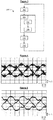
- the figure 4 is a chronogram of phase currents in an electric motor supplied by an inverter controlled according to the method of the state of the art 3-stage intersective PWM.
- the figure 5 is a chronogram of phase currents in an electric motor supplied by an inverter controlled according to a control device according to the invention. As can be seen by comparing the figures 4 and 5 , the invention makes it possible to reduce unwanted current peaks, originating from the use in the method of the state of the art of homopolar parasitic voltage components.
- the invention can easily be adapted to an inverter for an N-phase motor.
- the space Esp of the phases of the motor is of dimension N.
- the volume is defined by N + 1 vectors.
- the groups of states of the inverter could have more than N + 1 states. In this case, these states would be associated with predetermined vectors defining a volume other than a tetrahedron.
- the battery 102 could be replaced by another source of DC voltage.
Landscapes
- Engineering & Computer Science (AREA)
- Power Engineering (AREA)
- Databases & Information Systems (AREA)
- Inverter Devices (AREA)
- Control Of Ac Motors In General (AREA)
Claims (10)
- Vorrichtung zur Steuerung (118) eines Wechselrichters (112), der bestimmt ist, an einen Motor (104) angeschlossen zu sein, der N Phasen (106, 108, 110) aufweist, die bestimmt sind, jeweils N Phasenspannungen (U, V, W) anzulegen, wobei die N Phasenspannungen (U, V, W) einen Vektorraum (Esp) definieren, von dem jede Phasenspannung (U, V, W) eine Dimension bildet, wobei N größer oder gleich drei ist, wobei der Wechselrichter (112) eingerichtet ist, um mehrere Zustände anzunehmen, wobei er in jedem derselben eingerichtet ist, um vorher festgelegte Phasenspannungen auf die Phasen (106, 108, 110) des Motors (104) anzulegen, wobei die vorher festgelegten Phasenspannungen jedes Zustands des Wechselrichters (112) einen vorher festgelegten Vektor (M1...M27) im Vektorraum (Esp) bilden, wobei die Steuerungsvorrichtung (118) aufweist:- eine Einheit, um für ein Zeitintervall Phasenspannungssollwerte zu empfangen, die einen Sollvektor im Vektorraum (Esp) bilden,- eine Einheit, um mindestens N+1 Zustände des Wechselrichters (112) auszuwählen, die jeweils mindestens N+1 vorher festgelegten Vektoren (M1...M27) zugeordnet sind, die ein Volumen im Vektorraum (Esp) definieren, das den Sollvektor enthält,- eine Einheit, um den Wechselrichter (112) über das Zeitintervall zu steuern, um ihn nacheinander in die ausgewählten Zustände zu versetzen, damit er im Wesentlichen im Mittel über das Zeitintervall die Phasenspannungssollwerte anlegt,wobei die Steuerungsvorrichtung (118) derart ist, dass die Auswahl der mindestens N+1 Zustände des Wechselrichters (112) aus Gruppen von mindestens N+1 Zuständen des Wechselrichters (112) durchgeführt wird, wobei die mindestens N+1 Zustände des Wechselrichters (112) aus mindestens einer der Gruppen jeweils mindestens N+1 vorher festgelegten Vektoren (M1...M27) zugeordnet sind, von denen mindestens N von vorher festgelegen Phasenspannungen mit der Summe Null gebildet sind und von denen mindestens einer von vorher festgelegten Phasenspannungen mit der Summe ungleich Null gebildet ist.
- Steuerungsvorrichtung (118) nach Anspruch 1, wobei jede Gruppe einen Zustand des Wechselrichters (112) aufweist, der dem Vektor Null (M14) des Vektorraums (Esp) zugeordnet ist, für den die vorher festgelegten Phasenspannungen alle Null sind.
- Steuerungsvorrichtung (118) nach Anspruch 1 oder 2, wobei sich die von den vorher festgelegten Vektoren (M1...M27) definierten Volumen, die den Zuständen des Wechselrichters (112) der Gruppen zugeordnet sind, nicht überschneiden.
- Steuerungsvorrichtung (118) nach einem der Ansprüche 1 bis 3, wobei jede Gruppe von Zuständen des Wechselrichters (112) genau N+1 Zustände des Wechselrichters (112) aufweist.
- Steuerungsvorrichtung (118) nach einem der Ansprüche 1 bis 4, wobei mindestens eine Gruppe von Zuständen des Wechselrichters (112) genau N-1 Zustände aufweist, die jeweils N-1 vorher festgelegten Vektoren (M1...M27) zugeordnet sind, die jeweils von vorher festgelegten Phasenspannungen gebildet sind, deren Summe Null ist.
- Steuerungsvorrichtung (118) nach einem der Ansprüche 1 bis 5, wobei N gleich drei ist.
- Elektrische Anlage (100), aufweisend:- einen Wechselrichter (112), der bestimmt ist, an einen Motor (104) angeschlossen zu sein, der N Phasen (106, 108, 110) aufweist, die bestimmt sind, jeweils N Phasenspannungen (U, V, W) anzulegen, wobei die N Phasenspannungen (U, V, W) einen Vektorraum (Esp) definieren, von dem jede Phasenspannung (U, V, W) eine Dimension bildet, wobei N größer oder gleich drei ist, wobei der Wechselrichter (112) eingerichtet ist, um mehrere Zustände anzunehmen, wobei er in jedem derselben eingerichtet ist, um vorher festgelegte Phasenspannungen auf die Phasen (106, 108, 110) des Motors (104) anzulegen, wobei die vorher festgelegten Phasenspannungen jedes Zustands des Wechselrichters (112) einen vorher festgelegten Vektor (M1...M27) im Vektorraum (Esp) bilden- eine Steuerungsvorrichtung (118) des Wechselrichters (112) nach einem der Ansprüche 1 bis 6.
- Elektrische Anlage (100) nach Anspruch 7, wobei der Wechselrichter (112) aufweist:- eine erste Klemme (114) und eine zweite Klemme (116), zwischen denen eine Gleichspannung (E) bestimmt ist, angelegt zu sein,- für jedes Phasenende einen Umschaltarm (106A, 106B, 108A, 108B, 110A, 110B), aufweisend zwei Schalter, die aneinander in einem Mittelpunkt (UA, UB, VA, VB, WA, WB) angeschlossen sind, an den das entsprechende Phasenende bestimmt ist, angeschlossen zu sein, wobei ein erster Schalter an die erste Klemme (114) angeschlossen ist, wobei der zweite Schalter an die zweite Klemme (116) angeschlossen ist,wobei jeder Schalter eingerichtet ist, einen offenen Zustand und einen geschlossenen Zustand anzunehmen, wobei jeder Zustand des Wechselrichters (112) von einer Kombination von Zuständen der Schalter definiert ist.
- Verfahren zur Steuerung (300) eines Wechselrichters (112), der bestimmt ist, an einen Motor (104) angeschlossen zu sein, der N Phasen (106, 108, 110) aufweist, die bestimmt sind, jeweils N Phasenspannungen (U, V, W) anzulegen, wobei die N Phasenspannungen (U, V, W) einen Vektorraum (Esp) definieren, von dem jede Phasenspannung (U, V, W) eine Dimension bildet, wobei N größer oder gleich drei ist, wobei der Wechselrichter (112) eingerichtet ist, um mehrere Zustände anzunehmen, wobei er in jedem derselben eingerichtet ist, um vorher festgelegte Phasenspannungen auf die Phasen (106, 108, 110) des Motors (104) anzulegen, wobei die vorher festgelegten Phasenspannungen jedes Zustands des Wechselrichters (112) einen vorher festgelegten Vektor (M1...M27) im Vektorraum (Esp) bilden, wobei das Steuerungsverfahren (300) aufweist:- Empfangen, für ein Zeitintervall, Phasenspannungssollwerte, die einen Sollvektor im Vektorraum (Esp) bilden,- Auswählen von mindestens N+1 Zuständen des Wechselrichters (112), die jeweils mindestens N+1 vorher festgelegten Vektoren (M1...M27) zugeordnet sind, die ein Volumen im Vektorraum (Esp) definieren, das den Sollvektor enthält,- Steuern des Wechselrichters (112) über das Zeitintervall, um ihn nacheinander in die ausgewählten Zustände zu versetzen, damit er im Wesentlichen im Mittel über das Zeitintervall die Phasenspannungssollwerte anlegt,wobei das Steuerungsverfahren (300) derart ist, dass die Auswahl der mindestens N+1 Zustände des Wechselrichters (112) aus Gruppen von mindestens N+1 Zuständen des Wechselrichters (112) durchgeführt wird, wobei die mindestens N+1 Zustände des Wechselrichters (112) aus mindestens einer der Gruppen jeweils mindestens N+1 vorher festgelegten Vektoren (M1...M27) zugeordnet sind, von denen mindestens N von vorher festgelegen Phasenspannungen mit der Summe Null gebildet sind und von denen mindestens einer von vorher festgelegten Phasenspannungen mit der Summe ungleich Null gebildet ist.
- Rechnerprogramm, umfassend Befehle, die die elektrische Anlage nach Anspruch 7 steuern, um die Schritte der Methode nach Anspruch 9 auszuführen.
Applications Claiming Priority (2)
| Application Number | Priority Date | Filing Date | Title |
|---|---|---|---|
| FR1651265A FR3047857B1 (fr) | 2016-02-17 | 2016-02-17 | Dispositif de commande d'un onduleur, installation electrique comportant un tel dispositif, procede de commande d'un onduleur et programme d'ordinateur correspondant |
| PCT/EP2017/053291 WO2017140676A1 (fr) | 2016-02-17 | 2017-02-14 | Dispositif de commande d'un onduleur, installation electrique comportant un tel dispositif, procede de commande d'un onduleur et programme d'ordinateur correspondant |
Publications (2)
| Publication Number | Publication Date |
|---|---|
| EP3417541A1 EP3417541A1 (de) | 2018-12-26 |
| EP3417541B1 true EP3417541B1 (de) | 2020-06-10 |
Family
ID=56008707
Family Applications (1)
| Application Number | Title | Priority Date | Filing Date |
|---|---|---|---|
| EP17707488.7A Active EP3417541B1 (de) | 2016-02-17 | 2017-02-14 | Vorrichtung zur steuerung eines wechselrichters, elektrische anlage mit solch einer vorrichtung, verfahren zur steuerung eines wechselrichters und entsprechendes computerprogramm |
Country Status (5)
| Country | Link |
|---|---|
| US (1) | US10978985B2 (de) |
| EP (1) | EP3417541B1 (de) |
| CN (1) | CN108702124B (de) |
| FR (1) | FR3047857B1 (de) |
| WO (1) | WO2017140676A1 (de) |
Family Cites Families (9)
| Publication number | Priority date | Publication date | Assignee | Title |
|---|---|---|---|---|
| JPH0475495A (ja) * | 1990-07-17 | 1992-03-10 | Mitsubishi Electric Corp | 3相インバータの制御方法 |
| US5552977A (en) * | 1995-06-20 | 1996-09-03 | Ford Motor Company | Three phase inverter circuit with improved transition from SVPWM to six step operation |
| KR100488529B1 (ko) * | 2003-05-20 | 2005-05-11 | 삼성전자주식회사 | 3상모터구동용 인버터의 제어장치 및 제어방법 |
| US9130482B2 (en) * | 2013-02-20 | 2015-09-08 | Infineon Technologies Ag | Pseudo zero vectors for space vector modulation and enhanced space vector modulation |
| JP5737445B2 (ja) * | 2013-03-05 | 2015-06-17 | ダイキン工業株式会社 | 電力変換器制御装置 |
| FR3004603B1 (fr) * | 2013-04-10 | 2015-07-03 | Valeo Systemes De Controle Moteur | Systeme d’entrainement rotatif, procede de commande d’un onduleur et programme d’ordinateur associe |
| FR3015804B1 (fr) * | 2013-12-20 | 2016-01-29 | Valeo Sys Controle Moteur Sas | Systeme d'entrainement, procede de commande d'un onduleur et programme d'ordinateur associe |
| FR3043865B1 (fr) * | 2015-11-12 | 2018-09-21 | Universite Blaise Pascal- Clermont Ii | Procede et dispositif de conversion de courant, vehicule comportant un tel dispositif |
| US10425017B2 (en) * | 2016-10-25 | 2019-09-24 | Infineon Technologies Ag | Method and apparatus for reducing current sensor power loss |
-
2016
- 2016-02-17 FR FR1651265A patent/FR3047857B1/fr active Active
-
2017
- 2017-02-14 CN CN201780012772.9A patent/CN108702124B/zh active Active
- 2017-02-14 WO PCT/EP2017/053291 patent/WO2017140676A1/fr not_active Ceased
- 2017-02-14 US US15/998,901 patent/US10978985B2/en active Active
- 2017-02-14 EP EP17707488.7A patent/EP3417541B1/de active Active
Non-Patent Citations (1)
| Title |
|---|
| None * |
Also Published As
| Publication number | Publication date |
|---|---|
| CN108702124B (zh) | 2022-05-17 |
| US10978985B2 (en) | 2021-04-13 |
| WO2017140676A1 (fr) | 2017-08-24 |
| CN108702124A (zh) | 2018-10-23 |
| EP3417541A1 (de) | 2018-12-26 |
| US20200067444A1 (en) | 2020-02-27 |
| FR3047857B1 (fr) | 2018-03-16 |
| FR3047857A1 (fr) | 2017-08-18 |
Similar Documents
| Publication | Publication Date | Title |
|---|---|---|
| EP2375556B1 (de) | Steuerverfahren eines Wechselrichters vom Typ NPC | |
| US9106177B2 (en) | Method and system for sensorless control of an electric motor | |
| US20160294317A1 (en) | Control apparatus for electric power inverter | |
| EP1964257B1 (de) | Mehrphasen-spannungsumsetzer-steuerverfahren | |
| EP3646681A1 (de) | Spannungswandler, verfahren zur herstellung solch eines spannungswandlers und anordnung eines hauptmoduls und eines anschlussblockmoduls zur ausbildung solch eines spannungswandlers | |
| WO2017140676A1 (fr) | Dispositif de commande d'un onduleur, installation electrique comportant un tel dispositif, procede de commande d'un onduleur et programme d'ordinateur correspondant | |
| CN113687126B (zh) | 单电阻电流采样方法及其装置 | |
| EP3649730A1 (de) | Verfahren zur steuerung eines dreiphasigen gleichrichters | |
| Ali et al. | Finite control set model predictive direct current control strategy with constraints applying to drive three-phase induction motor. | |
| FR3089075A1 (fr) | Procede de commande d’une machine electrique triphasee | |
| EP4229748A1 (de) | Verfahren und system zur steuerung einer elektrischen maschine zur bestimmung optimaler stromsollwerte | |
| EP3381113B1 (de) | Regenerativer undeland snubber für wechselrichter halbbrücken | |
| CN114499333A (zh) | 交流旋转电机的控制装置 | |
| WO2020170324A1 (ja) | 電力変換装置および電動パワーステアリング装置 | |
| EP3375086A1 (de) | Stromumwandlungsverfahren und -vorrichtung, fahrzeug mit solch einer vorrichtung | |
| CN114844422A (zh) | 一种电机输出转矩的控制方法、装置及电子设备 | |
| EP1528665A1 (de) | Methode und Vorrichtung zur Motorsteuerung | |
| WO2013072246A1 (fr) | Procédé et système de commande pour corriger les tensions à appliquer à une charge électrique | |
| FR3073993B1 (fr) | Procede de commande d'un onduleur triphase | |
| EP3086437B1 (de) | Batterieladegerät, elektrisches system mit einem solchen batterieladegerät, elektrisches fahrzeug mit einem solchen system | |
| JP2005295625A (ja) | 電力変換装置 | |
| EP1696549A1 (de) | Umrichtersteuervorrichtung und -verfahren und elektrischer Umrichter mit solcher Vorrichtung | |
| EP2717445B1 (de) | Steuerungsverfahren in einem Leistungswandler zur Sicherstellung der Feststellbarkeit eines Kurzschlusses | |
| Rosic et al. | Electromotive force compensation in direct torque control with discretized voltage intensities | |
| EP3195466B1 (de) | Verfahren zur steuerung einer umrichtervorrichtung und zugehörige steuerungsvorrichtung |
Legal Events
| Date | Code | Title | Description |
|---|---|---|---|
| STAA | Information on the status of an ep patent application or granted ep patent |
Free format text: STATUS: UNKNOWN |
|
| STAA | Information on the status of an ep patent application or granted ep patent |
Free format text: STATUS: THE INTERNATIONAL PUBLICATION HAS BEEN MADE |
|
| PUAI | Public reference made under article 153(3) epc to a published international application that has entered the european phase |
Free format text: ORIGINAL CODE: 0009012 |
|
| STAA | Information on the status of an ep patent application or granted ep patent |
Free format text: STATUS: REQUEST FOR EXAMINATION WAS MADE |
|
| 17P | Request for examination filed |
Effective date: 20180813 |
|
| AK | Designated contracting states |
Kind code of ref document: A1 Designated state(s): AL AT BE BG CH CY CZ DE DK EE ES FI FR GB GR HR HU IE IS IT LI LT LU LV MC MK MT NL NO PL PT RO RS SE SI SK SM TR |
|
| AX | Request for extension of the european patent |
Extension state: BA ME |
|
| RAP1 | Party data changed (applicant data changed or rights of an application transferred) |
Owner name: VALEO SIEMENS EAUTOMOTIVE FRANCE SAS |
|
| DAV | Request for validation of the european patent (deleted) | ||
| DAX | Request for extension of the european patent (deleted) | ||
| GRAP | Despatch of communication of intention to grant a patent |
Free format text: ORIGINAL CODE: EPIDOSNIGR1 |
|
| STAA | Information on the status of an ep patent application or granted ep patent |
Free format text: STATUS: GRANT OF PATENT IS INTENDED |
|
| INTG | Intention to grant announced |
Effective date: 20190902 |
|
| GRAS | Grant fee paid |
Free format text: ORIGINAL CODE: EPIDOSNIGR3 |
|
| GRAJ | Information related to disapproval of communication of intention to grant by the applicant or resumption of examination proceedings by the epo deleted |
Free format text: ORIGINAL CODE: EPIDOSDIGR1 |
|
| GRAL | Information related to payment of fee for publishing/printing deleted |
Free format text: ORIGINAL CODE: EPIDOSDIGR3 |
|
| STAA | Information on the status of an ep patent application or granted ep patent |
Free format text: STATUS: REQUEST FOR EXAMINATION WAS MADE |
|
| GRAP | Despatch of communication of intention to grant a patent |
Free format text: ORIGINAL CODE: EPIDOSNIGR1 |
|
| STAA | Information on the status of an ep patent application or granted ep patent |
Free format text: STATUS: GRANT OF PATENT IS INTENDED |
|
| INTC | Intention to grant announced (deleted) | ||
| INTG | Intention to grant announced |
Effective date: 20200121 |
|
| GRAA | (expected) grant |
Free format text: ORIGINAL CODE: 0009210 |
|
| STAA | Information on the status of an ep patent application or granted ep patent |
Free format text: STATUS: THE PATENT HAS BEEN GRANTED |
|
| AK | Designated contracting states |
Kind code of ref document: B1 Designated state(s): AL AT BE BG CH CY CZ DE DK EE ES FI FR GB GR HR HU IE IS IT LI LT LU LV MC MK MT NL NO PL PT RO RS SE SI SK SM TR |
|
| REG | Reference to a national code |
Ref country code: GB Ref legal event code: FG4D Free format text: NOT ENGLISH |
|
| REG | Reference to a national code |
Ref country code: AT Ref legal event code: REF Ref document number: 1279977 Country of ref document: AT Kind code of ref document: T Effective date: 20200615 Ref country code: CH Ref legal event code: EP |
|
| REG | Reference to a national code |
Ref country code: DE Ref legal event code: R096 Ref document number: 602017017960 Country of ref document: DE |
|
| REG | Reference to a national code |
Ref country code: IE Ref legal event code: FG4D Free format text: LANGUAGE OF EP DOCUMENT: FRENCH |
|
| REG | Reference to a national code |
Ref country code: LT Ref legal event code: MG4D |
|
| PG25 | Lapsed in a contracting state [announced via postgrant information from national office to epo] |
Ref country code: LT Free format text: LAPSE BECAUSE OF FAILURE TO SUBMIT A TRANSLATION OF THE DESCRIPTION OR TO PAY THE FEE WITHIN THE PRESCRIBED TIME-LIMIT Effective date: 20200610 Ref country code: GR Free format text: LAPSE BECAUSE OF FAILURE TO SUBMIT A TRANSLATION OF THE DESCRIPTION OR TO PAY THE FEE WITHIN THE PRESCRIBED TIME-LIMIT Effective date: 20200911 Ref country code: NO Free format text: LAPSE BECAUSE OF FAILURE TO SUBMIT A TRANSLATION OF THE DESCRIPTION OR TO PAY THE FEE WITHIN THE PRESCRIBED TIME-LIMIT Effective date: 20200910 Ref country code: FI Free format text: LAPSE BECAUSE OF FAILURE TO SUBMIT A TRANSLATION OF THE DESCRIPTION OR TO PAY THE FEE WITHIN THE PRESCRIBED TIME-LIMIT Effective date: 20200610 Ref country code: SE Free format text: LAPSE BECAUSE OF FAILURE TO SUBMIT A TRANSLATION OF THE DESCRIPTION OR TO PAY THE FEE WITHIN THE PRESCRIBED TIME-LIMIT Effective date: 20200610 |
|
| REG | Reference to a national code |
Ref country code: NL Ref legal event code: MP Effective date: 20200610 |
|
| PG25 | Lapsed in a contracting state [announced via postgrant information from national office to epo] |
Ref country code: HR Free format text: LAPSE BECAUSE OF FAILURE TO SUBMIT A TRANSLATION OF THE DESCRIPTION OR TO PAY THE FEE WITHIN THE PRESCRIBED TIME-LIMIT Effective date: 20200610 Ref country code: RS Free format text: LAPSE BECAUSE OF FAILURE TO SUBMIT A TRANSLATION OF THE DESCRIPTION OR TO PAY THE FEE WITHIN THE PRESCRIBED TIME-LIMIT Effective date: 20200610 Ref country code: LV Free format text: LAPSE BECAUSE OF FAILURE TO SUBMIT A TRANSLATION OF THE DESCRIPTION OR TO PAY THE FEE WITHIN THE PRESCRIBED TIME-LIMIT Effective date: 20200610 Ref country code: BG Free format text: LAPSE BECAUSE OF FAILURE TO SUBMIT A TRANSLATION OF THE DESCRIPTION OR TO PAY THE FEE WITHIN THE PRESCRIBED TIME-LIMIT Effective date: 20200910 |
|
| REG | Reference to a national code |
Ref country code: AT Ref legal event code: MK05 Ref document number: 1279977 Country of ref document: AT Kind code of ref document: T Effective date: 20200610 |
|
| PG25 | Lapsed in a contracting state [announced via postgrant information from national office to epo] |
Ref country code: AL Free format text: LAPSE BECAUSE OF FAILURE TO SUBMIT A TRANSLATION OF THE DESCRIPTION OR TO PAY THE FEE WITHIN THE PRESCRIBED TIME-LIMIT Effective date: 20200610 Ref country code: NL Free format text: LAPSE BECAUSE OF FAILURE TO SUBMIT A TRANSLATION OF THE DESCRIPTION OR TO PAY THE FEE WITHIN THE PRESCRIBED TIME-LIMIT Effective date: 20200610 |
|
| PG25 | Lapsed in a contracting state [announced via postgrant information from national office to epo] |
Ref country code: CZ Free format text: LAPSE BECAUSE OF FAILURE TO SUBMIT A TRANSLATION OF THE DESCRIPTION OR TO PAY THE FEE WITHIN THE PRESCRIBED TIME-LIMIT Effective date: 20200610 Ref country code: ES Free format text: LAPSE BECAUSE OF FAILURE TO SUBMIT A TRANSLATION OF THE DESCRIPTION OR TO PAY THE FEE WITHIN THE PRESCRIBED TIME-LIMIT Effective date: 20200610 Ref country code: RO Free format text: LAPSE BECAUSE OF FAILURE TO SUBMIT A TRANSLATION OF THE DESCRIPTION OR TO PAY THE FEE WITHIN THE PRESCRIBED TIME-LIMIT Effective date: 20200610 Ref country code: PT Free format text: LAPSE BECAUSE OF FAILURE TO SUBMIT A TRANSLATION OF THE DESCRIPTION OR TO PAY THE FEE WITHIN THE PRESCRIBED TIME-LIMIT Effective date: 20201012 Ref country code: IT Free format text: LAPSE BECAUSE OF FAILURE TO SUBMIT A TRANSLATION OF THE DESCRIPTION OR TO PAY THE FEE WITHIN THE PRESCRIBED TIME-LIMIT Effective date: 20200610 Ref country code: EE Free format text: LAPSE BECAUSE OF FAILURE TO SUBMIT A TRANSLATION OF THE DESCRIPTION OR TO PAY THE FEE WITHIN THE PRESCRIBED TIME-LIMIT Effective date: 20200610 Ref country code: AT Free format text: LAPSE BECAUSE OF FAILURE TO SUBMIT A TRANSLATION OF THE DESCRIPTION OR TO PAY THE FEE WITHIN THE PRESCRIBED TIME-LIMIT Effective date: 20200610 Ref country code: SM Free format text: LAPSE BECAUSE OF FAILURE TO SUBMIT A TRANSLATION OF THE DESCRIPTION OR TO PAY THE FEE WITHIN THE PRESCRIBED TIME-LIMIT Effective date: 20200610 |
|
| PG25 | Lapsed in a contracting state [announced via postgrant information from national office to epo] |
Ref country code: IS Free format text: LAPSE BECAUSE OF FAILURE TO SUBMIT A TRANSLATION OF THE DESCRIPTION OR TO PAY THE FEE WITHIN THE PRESCRIBED TIME-LIMIT Effective date: 20201010 Ref country code: SK Free format text: LAPSE BECAUSE OF FAILURE TO SUBMIT A TRANSLATION OF THE DESCRIPTION OR TO PAY THE FEE WITHIN THE PRESCRIBED TIME-LIMIT Effective date: 20200610 Ref country code: PL Free format text: LAPSE BECAUSE OF FAILURE TO SUBMIT A TRANSLATION OF THE DESCRIPTION OR TO PAY THE FEE WITHIN THE PRESCRIBED TIME-LIMIT Effective date: 20200610 |
|
| REG | Reference to a national code |
Ref country code: DE Ref legal event code: R097 Ref document number: 602017017960 Country of ref document: DE |
|
| PLBE | No opposition filed within time limit |
Free format text: ORIGINAL CODE: 0009261 |
|
| STAA | Information on the status of an ep patent application or granted ep patent |
Free format text: STATUS: NO OPPOSITION FILED WITHIN TIME LIMIT |
|
| PG25 | Lapsed in a contracting state [announced via postgrant information from national office to epo] |
Ref country code: DK Free format text: LAPSE BECAUSE OF FAILURE TO SUBMIT A TRANSLATION OF THE DESCRIPTION OR TO PAY THE FEE WITHIN THE PRESCRIBED TIME-LIMIT Effective date: 20200610 |
|
| 26N | No opposition filed |
Effective date: 20210311 |
|
| PG25 | Lapsed in a contracting state [announced via postgrant information from national office to epo] |
Ref country code: SI Free format text: LAPSE BECAUSE OF FAILURE TO SUBMIT A TRANSLATION OF THE DESCRIPTION OR TO PAY THE FEE WITHIN THE PRESCRIBED TIME-LIMIT Effective date: 20200610 |
|
| PG25 | Lapsed in a contracting state [announced via postgrant information from national office to epo] |
Ref country code: MC Free format text: LAPSE BECAUSE OF FAILURE TO SUBMIT A TRANSLATION OF THE DESCRIPTION OR TO PAY THE FEE WITHIN THE PRESCRIBED TIME-LIMIT Effective date: 20200610 |
|
| REG | Reference to a national code |
Ref country code: BE Ref legal event code: MM Effective date: 20210228 |
|
| PG25 | Lapsed in a contracting state [announced via postgrant information from national office to epo] |
Ref country code: CH Free format text: LAPSE BECAUSE OF NON-PAYMENT OF DUE FEES Effective date: 20210228 Ref country code: LU Free format text: LAPSE BECAUSE OF NON-PAYMENT OF DUE FEES Effective date: 20210214 Ref country code: LI Free format text: LAPSE BECAUSE OF NON-PAYMENT OF DUE FEES Effective date: 20210228 |
|
| PG25 | Lapsed in a contracting state [announced via postgrant information from national office to epo] |
Ref country code: IE Free format text: LAPSE BECAUSE OF NON-PAYMENT OF DUE FEES Effective date: 20210214 |
|
| PG25 | Lapsed in a contracting state [announced via postgrant information from national office to epo] |
Ref country code: BE Free format text: LAPSE BECAUSE OF NON-PAYMENT OF DUE FEES Effective date: 20210228 |
|
| PG25 | Lapsed in a contracting state [announced via postgrant information from national office to epo] |
Ref country code: CY Free format text: LAPSE BECAUSE OF FAILURE TO SUBMIT A TRANSLATION OF THE DESCRIPTION OR TO PAY THE FEE WITHIN THE PRESCRIBED TIME-LIMIT Effective date: 20200610 |
|
| PG25 | Lapsed in a contracting state [announced via postgrant information from national office to epo] |
Ref country code: HU Free format text: LAPSE BECAUSE OF FAILURE TO SUBMIT A TRANSLATION OF THE DESCRIPTION OR TO PAY THE FEE WITHIN THE PRESCRIBED TIME-LIMIT; INVALID AB INITIO Effective date: 20170214 |
|
| P01 | Opt-out of the competence of the unified patent court (upc) registered |
Effective date: 20230629 |
|
| PG25 | Lapsed in a contracting state [announced via postgrant information from national office to epo] |
Ref country code: MK Free format text: LAPSE BECAUSE OF FAILURE TO SUBMIT A TRANSLATION OF THE DESCRIPTION OR TO PAY THE FEE WITHIN THE PRESCRIBED TIME-LIMIT Effective date: 20200610 |
|
| PG25 | Lapsed in a contracting state [announced via postgrant information from national office to epo] |
Ref country code: TR Free format text: LAPSE BECAUSE OF FAILURE TO SUBMIT A TRANSLATION OF THE DESCRIPTION OR TO PAY THE FEE WITHIN THE PRESCRIBED TIME-LIMIT Effective date: 20200610 |
|
| PG25 | Lapsed in a contracting state [announced via postgrant information from national office to epo] |
Ref country code: MT Free format text: LAPSE BECAUSE OF FAILURE TO SUBMIT A TRANSLATION OF THE DESCRIPTION OR TO PAY THE FEE WITHIN THE PRESCRIBED TIME-LIMIT Effective date: 20200610 |
|
| PGFP | Annual fee paid to national office [announced via postgrant information from national office to epo] |
Ref country code: GB Payment date: 20260219 Year of fee payment: 10 |
|
| PGFP | Annual fee paid to national office [announced via postgrant information from national office to epo] |
Ref country code: DE Payment date: 20260206 Year of fee payment: 10 |
|
| PGFP | Annual fee paid to national office [announced via postgrant information from national office to epo] |
Ref country code: FR Payment date: 20260227 Year of fee payment: 10 |