EP3417115B1 - Foundation for a wind mill - Google Patents
Foundation for a wind mill Download PDFInfo
- Publication number
- EP3417115B1 EP3417115B1 EP17709168.3A EP17709168A EP3417115B1 EP 3417115 B1 EP3417115 B1 EP 3417115B1 EP 17709168 A EP17709168 A EP 17709168A EP 3417115 B1 EP3417115 B1 EP 3417115B1
- Authority
- EP
- European Patent Office
- Prior art keywords
- foundation
- precast concrete
- pedestal
- elements
- concrete elements
- Prior art date
- Legal status (The legal status is an assumption and is not a legal conclusion. Google has not performed a legal analysis and makes no representation as to the accuracy of the status listed.)
- Active
Links
- 230000002787 reinforcement Effects 0.000 claims description 98
- 239000011178 precast concrete Substances 0.000 claims description 90
- NJPPVKZQTLUDBO-UHFFFAOYSA-N novaluron Chemical compound C1=C(Cl)C(OC(F)(F)C(OC(F)(F)F)F)=CC=C1NC(=O)NC(=O)C1=C(F)C=CC=C1F NJPPVKZQTLUDBO-UHFFFAOYSA-N 0.000 claims description 63
- 229910000831 Steel Inorganic materials 0.000 claims description 10
- 239000011796 hollow space material Substances 0.000 claims description 10
- 239000010959 steel Substances 0.000 claims description 10
- 239000011150 reinforced concrete Substances 0.000 claims description 6
- 238000003466 welding Methods 0.000 claims description 6
- 239000000463 material Substances 0.000 description 23
- 239000004567 concrete Substances 0.000 description 21
- 238000004519 manufacturing process Methods 0.000 description 7
- 238000009412 basement excavation Methods 0.000 description 4
- 238000004873 anchoring Methods 0.000 description 3
- 230000001174 ascending effect Effects 0.000 description 3
- 238000005266 casting Methods 0.000 description 3
- 230000008878 coupling Effects 0.000 description 3
- 238000010168 coupling process Methods 0.000 description 3
- 238000005859 coupling reaction Methods 0.000 description 3
- 238000009415 formwork Methods 0.000 description 3
- 238000009434 installation Methods 0.000 description 3
- 239000002184 metal Substances 0.000 description 3
- 239000004753 textile Substances 0.000 description 3
- 238000005452 bending Methods 0.000 description 2
- 238000009826 distribution Methods 0.000 description 2
- 239000011210 fiber-reinforced concrete Substances 0.000 description 2
- XLYOFNOQVPJJNP-UHFFFAOYSA-N water Substances O XLYOFNOQVPJJNP-UHFFFAOYSA-N 0.000 description 2
- OKTJSMMVPCPJKN-UHFFFAOYSA-N Carbon Chemical compound [C] OKTJSMMVPCPJKN-UHFFFAOYSA-N 0.000 description 1
- 239000004743 Polypropylene Substances 0.000 description 1
- 239000011398 Portland cement Substances 0.000 description 1
- 239000012615 aggregate Substances 0.000 description 1
- 239000011230 binding agent Substances 0.000 description 1
- 239000013590 bulk material Substances 0.000 description 1
- 229910052799 carbon Inorganic materials 0.000 description 1
- 230000006835 compression Effects 0.000 description 1
- 238000007906 compression Methods 0.000 description 1
- 238000010276 construction Methods 0.000 description 1
- 230000000694 effects Effects 0.000 description 1
- 239000002657 fibrous material Substances 0.000 description 1
- 239000003365 glass fiber Substances 0.000 description 1
- 238000011065 in-situ storage Methods 0.000 description 1
- 238000012423 maintenance Methods 0.000 description 1
- 238000000034 method Methods 0.000 description 1
- 239000000203 mixture Substances 0.000 description 1
- -1 polypropylene Polymers 0.000 description 1
- 229920001155 polypropylene Polymers 0.000 description 1
- 230000003014 reinforcing effect Effects 0.000 description 1
- 230000000284 resting effect Effects 0.000 description 1
- 239000002689 soil Substances 0.000 description 1
- 230000003068 static effect Effects 0.000 description 1
- 238000003860 storage Methods 0.000 description 1
- 229920002994 synthetic fiber Polymers 0.000 description 1
Images


Classifications
-
- F—MECHANICAL ENGINEERING; LIGHTING; HEATING; WEAPONS; BLASTING
- F03—MACHINES OR ENGINES FOR LIQUIDS; WIND, SPRING, OR WEIGHT MOTORS; PRODUCING MECHANICAL POWER OR A REACTIVE PROPULSIVE THRUST, NOT OTHERWISE PROVIDED FOR
- F03D—WIND MOTORS
- F03D13/00—Assembly, mounting or commissioning of wind motors; Arrangements specially adapted for transporting wind motor components
- F03D13/20—Arrangements for mounting or supporting wind motors; Masts or towers for wind motors
- F03D13/22—Foundations specially adapted for wind motors
-
- E—FIXED CONSTRUCTIONS
- E02—HYDRAULIC ENGINEERING; FOUNDATIONS; SOIL SHIFTING
- E02D—FOUNDATIONS; EXCAVATIONS; EMBANKMENTS; UNDERGROUND OR UNDERWATER STRUCTURES
- E02D27/00—Foundations as substructures
- E02D27/32—Foundations for special purposes
- E02D27/42—Foundations for poles, masts or chimneys
- E02D27/425—Foundations for poles, masts or chimneys specially adapted for wind motors masts
-
- E—FIXED CONSTRUCTIONS
- E02—HYDRAULIC ENGINEERING; FOUNDATIONS; SOIL SHIFTING
- E02D—FOUNDATIONS; EXCAVATIONS; EMBANKMENTS; UNDERGROUND OR UNDERWATER STRUCTURES
- E02D27/00—Foundations as substructures
- E02D27/32—Foundations for special purposes
- E02D27/42—Foundations for poles, masts or chimneys
-
- E—FIXED CONSTRUCTIONS
- E02—HYDRAULIC ENGINEERING; FOUNDATIONS; SOIL SHIFTING
- E02D—FOUNDATIONS; EXCAVATIONS; EMBANKMENTS; UNDERGROUND OR UNDERWATER STRUCTURES
- E02D2200/00—Geometrical or physical properties
- E02D2200/16—Shapes
- E02D2200/1607—Shapes round, e.g. circle
- E02D2200/1621—Shapes round, e.g. circle made from multiple elements
-
- E—FIXED CONSTRUCTIONS
- E02—HYDRAULIC ENGINEERING; FOUNDATIONS; SOIL SHIFTING
- E02D—FOUNDATIONS; EXCAVATIONS; EMBANKMENTS; UNDERGROUND OR UNDERWATER STRUCTURES
- E02D2200/00—Geometrical or physical properties
- E02D2200/16—Shapes
- E02D2200/165—Shapes polygonal
- E02D2200/1664—Shapes polygonal made from multiple elements
-
- E—FIXED CONSTRUCTIONS
- E02—HYDRAULIC ENGINEERING; FOUNDATIONS; SOIL SHIFTING
- E02D—FOUNDATIONS; EXCAVATIONS; EMBANKMENTS; UNDERGROUND OR UNDERWATER STRUCTURES
- E02D2250/00—Production methods
-
- E—FIXED CONSTRUCTIONS
- E02—HYDRAULIC ENGINEERING; FOUNDATIONS; SOIL SHIFTING
- E02D—FOUNDATIONS; EXCAVATIONS; EMBANKMENTS; UNDERGROUND OR UNDERWATER STRUCTURES
- E02D2300/00—Materials
- E02D2300/0004—Synthetics
- E02D2300/0018—Cement used as binder
- E02D2300/002—Concrete
-
- E—FIXED CONSTRUCTIONS
- E02—HYDRAULIC ENGINEERING; FOUNDATIONS; SOIL SHIFTING
- E02D—FOUNDATIONS; EXCAVATIONS; EMBANKMENTS; UNDERGROUND OR UNDERWATER STRUCTURES
- E02D2600/00—Miscellaneous
- E02D2600/20—Miscellaneous comprising details of connection between elements
-
- E—FIXED CONSTRUCTIONS
- E02—HYDRAULIC ENGINEERING; FOUNDATIONS; SOIL SHIFTING
- E02D—FOUNDATIONS; EXCAVATIONS; EMBANKMENTS; UNDERGROUND OR UNDERWATER STRUCTURES
- E02D27/00—Foundations as substructures
- E02D27/10—Deep foundations
- E02D27/12—Pile foundations
-
- F—MECHANICAL ENGINEERING; LIGHTING; HEATING; WEAPONS; BLASTING
- F05—INDEXING SCHEMES RELATING TO ENGINES OR PUMPS IN VARIOUS SUBCLASSES OF CLASSES F01-F04
- F05B—INDEXING SCHEME RELATING TO WIND, SPRING, WEIGHT, INERTIA OR LIKE MOTORS, TO MACHINES OR ENGINES FOR LIQUIDS COVERED BY SUBCLASSES F03B, F03D AND F03G
- F05B2240/00—Components
- F05B2240/90—Mounting on supporting structures or systems
- F05B2240/91—Mounting on supporting structures or systems on a stationary structure
- F05B2240/912—Mounting on supporting structures or systems on a stationary structure on a tower
-
- Y—GENERAL TAGGING OF NEW TECHNOLOGICAL DEVELOPMENTS; GENERAL TAGGING OF CROSS-SECTIONAL TECHNOLOGIES SPANNING OVER SEVERAL SECTIONS OF THE IPC; TECHNICAL SUBJECTS COVERED BY FORMER USPC CROSS-REFERENCE ART COLLECTIONS [XRACs] AND DIGESTS
- Y02—TECHNOLOGIES OR APPLICATIONS FOR MITIGATION OR ADAPTATION AGAINST CLIMATE CHANGE
- Y02E—REDUCTION OF GREENHOUSE GAS [GHG] EMISSIONS, RELATED TO ENERGY GENERATION, TRANSMISSION OR DISTRIBUTION
- Y02E10/00—Energy generation through renewable energy sources
- Y02E10/70—Wind energy
- Y02E10/72—Wind turbines with rotation axis in wind direction
-
- Y—GENERAL TAGGING OF NEW TECHNOLOGICAL DEVELOPMENTS; GENERAL TAGGING OF CROSS-SECTIONAL TECHNOLOGIES SPANNING OVER SEVERAL SECTIONS OF THE IPC; TECHNICAL SUBJECTS COVERED BY FORMER USPC CROSS-REFERENCE ART COLLECTIONS [XRACs] AND DIGESTS
- Y02—TECHNOLOGIES OR APPLICATIONS FOR MITIGATION OR ADAPTATION AGAINST CLIMATE CHANGE
- Y02E—REDUCTION OF GREENHOUSE GAS [GHG] EMISSIONS, RELATED TO ENERGY GENERATION, TRANSMISSION OR DISTRIBUTION
- Y02E10/00—Energy generation through renewable energy sources
- Y02E10/70—Wind energy
- Y02E10/728—Onshore wind turbines
Definitions
- the invention refers to a foundation for a wind mill, comprising a circular or polygonal pedestal for supporting a wind mill tower and a plurality of ribs radiating radially outwardly from the pedestal, wherein the pedestal is divided into a plurality of circumferential sections, wherein a circumferential section and a rib are each integrally formed with one another, or are each formed, as a precast concrete element, wherein the precast concrete elements are made from reinforced concrete comprising a first reinforcement structure, in particular reinforcement bars, embedded into the precast concrete elements.
- the invention refers to a wind turbine comprising a mast and a rotor mounted on the mast, wherein the mast is mounted onto a foundation.
- a wind mill foundation of the initially defined kind is disclosed in WO 2004/101898 A2 .
- the manufacturing of the foundation of on-shore wind power installations requires a high manual and administrative effort and is very time consuming.
- the foundation is subjected to very high loads and has to be dimensioned accordingly.
- wind turbines have a tower having a height of up to 150 m und produce up to 6 MW.
- the tower or mast of wind turbines is made of reinforced concrete and is build by using precast concrete elements.
- the foundations for wind power installations have been produced essentially by digging out an excavation, introducing a granular subbase, erecting a foundation component, carrying out the necessary formwork and the reinforcing work and then filling the excavation with concrete, wherein the concrete is transported to the worksite by means of ready mix trucks and poured into the excavation.
- the foundation component is usually of a hollow-cylindrical configuration and is generally precast and is transported as a unit to the respective assembly location.
- the manufacturing of a wind mill foundation by on-site casting of concrete has a number of disadvantages. It requires complex logistics for planning the on-site manufacturing activities and it involves time-consuming and costly operations at the work site, such as building the formwork and the reinforcement structure as well as transporting concrete and casting the concrete. This is particularly true when considering that up to 1.000 m 3 of concrete may be required for large foundations.
- precast concrete elements In order to improve the process of building a foundation, it has already been proposed in WO 2004/101898 A2 to build the foundation by using precast concrete elements. Such concrete elements are produced in a precast plant and are transported to the worksite, where they are put into position by using a crane and then connected with each other. In this way, the duration of the building operations at the worksite may be reduced considerably.
- the precast concrete elements when connected to each other, form a foundation comprising a central pedestal and a plurality of ribs that radiate radially outwardly from the pedestal. Each precast concrete element forms one of the ribs and an associated circumferential section of the pedestal. The circumferential sections of the pedestal are connected to each other by screwed flanges. As described in WO 2004/101898 A2 , the precast concrete elements may be steel-reinforced. After having built the foundation, the tower or mast of the wind mill is erected on the pedestal and fixed to the pedestal by using anchor bolts.
- precast concrete elements By using precast concrete elements, the elements can be produced in a controlled environment, so that the concrete is afforded the opportunity to properly cure and be closely monitored by plant employees.
- the quality of the hardened concrete may be enhanced, because there is a greater control of the quality of materials and workmanship in a precast plant rather than on a construction site.
- financially, the forms used in a precast plant may be reused many times before they have to be replaced, which allow the cost of formwork per unit to be lower than for site-cast production.
- Wind turbines are subjected to loads and stresses of specific nature that must be taken up by the foundation.
- the wind itself acts in an unpredictable and varying manner.
- dynamic load components are acting on the structure due to vibrations and resonances.
- tower heights of 100 meters and more transfer a major eccentric load to the foundation due to a substantial overturning moment that is occurring. If the tower is exposed to a bending moment, the concrete of the foundation must resist the compression that occurs in the compressed zone and the reinforcement structure of the concrete must take up the tensile force in the opposite part of the foundation, because the concrete as such has a relatively low tensile strength.
- Foundations made from precast reinforced concrete elements have the advantage that the performance and the quality of the concrete are higher so that there is a reduced risk of crack-forming and better ability to resist dynamic and static loads.
- a drawback is that the precast concrete element must not exceed certain dimensions so that they may be transported from the precast plant to the work site.
- a substantial contribution to the stability of a foundation is achieved by backfilling of the excavation with soil or other backfill material onto the precast concrete elements of the foundation.
- the weight of the backfill material can be used to produce a vertical load onto the precast concrete elements that counteracts an eventual overturning moment.
- the load is most effectively acting on vertical surfaces of the foundation, such as base plates of the precast concrete elements.
- the base plates may have a limited width so that a clearance remains between neighbouring base plates. In the region of said clearance the backfill material cannot exert a vertical load onto the foundation that would counteract the overturning moment of the wind will.
- the transport facilities available for transporting the precast concrete elements from the precast plant to the work site limit the possible length thereof.
- the invention provides a foundation for a wind mill of the initially defined kind, comprising a circular or polygonal pedestal for supporting a wind mill tower and a plurality of ribs radiating radially outwardly from the pedestal, wherein the pedestal is divided into a plurality of circumferential sections, wherein a circumferential section and a rib are each integrally formed with one another, or are each formed, as a precast concrete element, wherein the precast concrete elements are made from reinforced concrete comprising a first reinforcement structure, in particular reinforcement bars, embedded into the precast concrete elements, which is characterized in that the clearance between two neighbouring precast concrete elements is each bridged by a bridging plate.
- the bridging plates are preferably realized as precast concrete plates. As the bridging plates are elements that are separate from the precast concrete elements that form the pedestal and the ribs of the foundation, they can be handled and transported separately.
- the bridging plates extend the horizontal surface area, onto which the backfilling material exerts a vertical force that counteracts the overturning moment of the wind mill. In particular, the surface area is extended to at least part of the clearance between neighbouring base plates and optionally to an area that is radially outside the diameter of the foundation as defined by the precast concrete elements that form the pedestal and the ribs.
- the bridging plates are supported by the base plates, so that the vertical load exerted by the backfilling material on the bridging plates may be transferred onto the foundation including the precast concrete elements.
- the facing sides of the bridging plates and of the base plates may be configured with a tongue-and-groove joint.
- a flat flexible material such as a textile sheet material, a mat or a geomembrane may be arranged to cover the base plates, the ribs and/or the bridging plates.
- the flat material may fulfil the same function as the bridging plates, which is to extend the surface, onto which the weight of the backfilling material is resting.
- the flat flexible material may be fixed to the pedestal and/or the ribs and/or the bridging plates by means of suitable connection elements, such as, e.g., hooks, eyes or threaded connections.
- the flat flexible material such as a textile sheet material, a mat or a geomembrane, may be used to further extend the horizontal surface area, onto which the backfilling material exerts a vertical force that counteracts the overturning moment of the wind mill.
- the flat flexible material may be fixed to the bridging plates and/or the ribs and arranged so as to radially protrude from the precast concrete elements in an outward direction.
- the flat flexible material may be fixed to the bridging plates and/or the ribs by conventional connection means.
- the bridging plates comprise an upper and a lower plate lying on top of each other, wherein the flat flexible material is clamped between the upper and the lower plate.
- an anchoring material or an anchoring means such as a tie bar, may be fixed to the precast concrete element, in particular the bridging plate, and extends beyond the foundation.
- the bridging plate has at least one opening, said at least one opening being preferably arranged near the outer periphery of the bridging plate, such as within the outer third of the radial extension of the bridging plate.
- the opening serves as a lead-through for metal reinforcement elements, such as metal reinforcement bars, that protrude from a pile of a pile foundation arranged below the bridging plates.
- the bridging plates serve as anchoring point for guy wire cables, said cables being suitable for supporting the tower of the windmill.
- the bridging plates may comprise fastening means for guy wire cables.
- the bridging plates may be loaded with weight, such as concrete blocks or bulk material.
- Another drawback of a foundation that is made from precast concrete elements is that, in contrast to foundations casted on-site, no monolithic structure is provided, so that technical solutions must be developed for securely connecting the precast concrete elements to each other so as to simulate a monolithic structure.
- a preferred embodiment of the invention provides that a second reinforcement structure is provided, which holds the precast concrete elements together and which is coupled to the first reinforcement structure.
- the second reinforcement structure may be of any kind suitable for rigidly holding the precast concrete elements together so as to form a monolithic structure.
- the second reinforcement structure is different from the first reinforcement structure and is therefore preferably not embedded in the precast concrete elements.
- the second reinforcement structure is coupled to the first reinforcement structure, which allows an uninterrupted load path between said reinforcement structures so that the forces introduced into the foundation are effectively distributed.
- coupling the first and the second reinforcement structures means that the forces acting on the first reinforcement structure are transmitted to the second reinforcement structure without concrete being interposed and vice versa.
- the first and second reinforcement structures may be directly connected to each other or via a rigid connecting element other than concrete.
- the first reinforcement structure preferably comprises reinforcement bars made of steel or a similar rigid material.
- the reinforcement bars extend in the longitudinal direction of the ribs. Additional reinforcement bars may extend perpendicularly or obliquely to the reinforcement bars extending in the longitudinal direction of the ribs. Additional reinforcement bars may also be arranged in the pedestal and extending in the axial direction thereof.
- the longitudinal reinforcement bars may preferably extend in a radial direction towards the centre of the foundation, wherein the longitudinal reinforcement bars may either be arranged in a horizontal plane or extend obliquely to the horizontal plane, in particular ascending towards the pedestal. In the latter case, the reinforcement bars are substantially aligned with the load path with regard to the forces that are led off from the pedestal radially outwardly.
- the second reinforcement structure preferably comprises a plurality of rigid longitudinal reinforcement elements, in particular steel beams or bars, that each connect the precast concrete elements of a pair of oppositely arranged precast concrete elements with each other in a manner traversing a hollow space encircled by the pedestal.
- the longitudinal reinforcement elements of the second reinforcement structure are coupled to the first reinforcement structure, in particular to the reinforcement bars, preferably to the reinforcement bars extending in the longitudinal direction of the ribs.
- the reinforcement bars embedded in oppositely arranged precast concrete elements are connected to each other by means of the longitudinal reinforcement elements of the second reinforcement structure, wherein a load transmitting path is formed between the first reinforcement structure of said oppositely arranged precast concrete elements.
- each pair of oppositely arranged precast concrete elements is connected by one of said rigid longitudinal reinforcement elements.
- a plurality of longitudinal reinforcement elements in particular steel bars or beams, are traversing the hollow space encircled by the pedestal. Since these traversing longitudinal reinforcement elements are all arranged diametrically, they meet in the centre of the pedestal, so that a symmetrical arrangement is achieved, which provides for an optimal distribution of the forces within the entire foundation.
- the longitudinal reinforcement elements may traverse the pedestal in a horizontal plane.
- the rigid longitudinal reinforcement elements are each fixed to one of said pair of oppositely arranged precast elements in an upper region thereof and to the other of said pair of oppositely arranged precast concrete elements in a bottom region thereof, so that they are extending obliquely with respect to a horizontal plane. Therefore, the reinforcement bars of oppositely arranged precast concrete elements are coupled to each other in at least two different planes, such as the top and the bottom plane.
- the rigid longitudinal reinforcement elements are connected to each other at their intersection that is arranged on a central axis of the pedestal. In this way, a central point in the axis of symmetry of the foundation is provided that allows for a load distribution in various directions.
- a preferred embodiment provides that the rigid longitudinal reinforcement elements of the second reinforcement structure and the first reinforcement structure, in particular the reinforcement bars, are connected to each other via a jacket arranged at an inner surface of the pedestal.
- Said jacket may be formed from a sheet steel casing that is fixed to the inner surface of the pedestal.
- the jacket may be embodied as a cylindrical jacket arranged at the inner cylindrical surface of the pedestal. The jacket serves to direct the load path from the first reinforcement structure to the second reinforcement structure and vice versa. This is achieved by rigidly connecting both the reinforcement bars of the first reinforcement structure and the reinforcement elements of the second reinforcement structure to the jacket.
- a preferred embodiment provides that the reinforcement bars of said first reinforcement structure are fixed to the jacket by welding. This may advantageously be achieved by arranging the reinforcement bars of said first reinforcement structure to protrude inwardly from the precast concrete elements, and preferably penetrate openings provided in the jacket.
- the weld may in this case be realized at the inner side of the jacket. Alternatively, the weld may be realized at the outer side of the jacket.
- the second reinforcement structure may be fixed to the jacket by welding or by a threaded connection.
- the hollow space within the pedestal may be used for different purposes, e.g. as a storage space or for undertaking maintenance works, and may therefore be equipped with stairs, platforms etc. Further, the hollow space may also be used for installing, accessing and maintaining post-tension cables that are arranged to stabilize the tower or mast of the wind mill.
- the precast concrete elements comprise a base plate for supporting the rib and are integrally formed with the same.
- the precast concrete element may have a cross section in the shape of an inverted "T", wherein the horizontal T-bar is formed by the base plate and the vertical T-bar is formed by the rib.
- the rib must not necessarily be realized strictly in the form of a vertical bar.
- the rib may also have a cross section that tapers towards the top. Further, the height of the rib may preferably continuously increase in a direction towards the pedestal.
- a continuously increasing height of the rib allows to adapt the cross sectional area of the rib to the force progression and may for example be realized with the upper surface or the upper rim of the rib being designed as a ramp ascending in a direction towards the pedestal.
- the rib may have a curved, namely concave, configuration of the upper surface or upper rim. In either case, the height of the rib may increase in a direction towards the pedestal so as to reach the height of the pedestal at the point where the rib merges into the pedestal.
- the reinforcement bars embedded into the rib may preferably extend substantially parallel to the upper rim of the rib, in particular parallel to the ascending ramp.
- the base plates of the precast concrete elements may have a rectangular shape. Alternatively, the plates may widen in the horizontal direction with increasing distance from the centre of the foundation.
- a preferred embodiment of the invention provides that said base plate comprises a rim section projecting inwardly into the hollow space encircled by the pedestal.
- the rim sections of all precast concrete elements together form a circumferential, in particular circular, rim, which circumferentially supports a central bottom plate that is arranged at the bottom of the pedestal.
- the precast concrete elements are constrained to each other by means of at least one post-tension cable that is arranged in a circumferential, in particular circular, passage realized in the pedestal.
- Such cables have the function of an additional reinforcement structure, but contrary to the inventive second reinforcement structure, the cables are not coupled to the first reinforcement structure embedded into the precast concrete elements.
- the side surfaces of neighbouring circumferential sections of the pedestal are pressed against each other.
- said side faces may comprise form fitting elements, such as a tongue and groove arrangement, cooperating with each other in order to secure the relative position of the segments.
- the installation of the precast concrete elements at the worksite is substantially simplified, if, in accordance with a preferred embodiment, neighbouring precast concrete elements, in their sections radiating outwardly from the pedestal, are spaced from each other in a circumferential direction.
- the base plates have a width dimension so that the base plates of neighbouring precast concrete elements do not touch each other. In this way, production tolerances in the production of the precast concrete elements can be accommodated.
- the concrete used to produce the precast concrete elements may be any type of concrete that is also typically used for casting in-situ concrete.
- concrete contains Portland cement as a hydraulic binder, which produces strength-forming phases by reacting and solidifying in contact with water.
- Fibre reinforced concrete may also be used to produce the precast concrete elements.
- the fibres may be made of any fibrous material that contributes to increasing the structural integrity, in particular the strength, the impact resistance and/or the durability, of the resulting concrete structure.
- Fibre-reinforced concrete contains short discrete reinforcement fibres that are uniformly distributed and randomly oriented.
- the reinforcement fibres are carbon fibres, synthetic fibres, in particular polypropylene fibres.
- the reinforcement fibres may be steel fibres, glass fibres, or natural fibres.
- the foundation carries an on-shore wind turbine comprising a mast and a rotor mounted on the mast, wherein the mast is mounted onto the pedestal of the inventive foundation with conventional means, such as by means of anchor bolts.
- the rotor has a horizontal rotation axis.
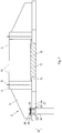
- Fig. 1 illustrates a wind mill foundation consisting of precast concrete elements
- Fig. 2 shows a precast concrete element as used in the foundation of Fig. 1
- Fig. 3 shows a cross section of the foundation
- Fig. 4 shows a top view of the foundation of Fig. 3
- Fig. 5 is a partial top view of an embodiment of the foundation according to the invention
- Fig. 6 shows a cross section of the foundation with a flexible sheet being fixed to the foundation
- Fig. 7 shows a cross section of the foundation being connected to a pile foundation.
- a foundation 1 that comprises a number of precast concrete elements 3.
- the foundation 1 comprises a circular pedestal 2 in the form of a hollow cylinder for supporting a wind mill tower.
- the foundation 1 further comprises a plurality of ribs 5 radiating radially outwardly from the pedestal 2.
- the pedestal 2 is divided into a plurality of circumferential sections 4 ( Fig. 2 ), wherein a circumferential section 4 and a rib 5 are each integrally formed with one another as a precast concrete element 3, as shown in Fig. 2 .
- the precast concrete element 3 further comprises a base plate 6 that is also integrally formed with the rib 5.
- the precast concrete elements 3 are made from reinforced concrete comprising reinforcement bars that are embedded into the precast concrete elements 3.
- the ribs are shown in Fig. 2 as a precast concrete element made in a single piece, the ribs may also be assembled from two or more rib sections. This is particularly advantageous, if a rib is to be realized that has a radial length that exceeds the allowable length of usual transporting facilities.
- two or more rib sections may be produced as separate precast concrete elements, transported to the work site separately and rigidly mounted together at the work site.
- said side faces may comprise form fitting elements 16, such as a trapezoidal tongue and groove arrangement, cooperating with each other in order to secure the relative position of the elements 3.
- the precast concrete elements 3 may be constrained to each other by means of at least one post-tension cable that can be arranged in a circumferential, in particular circular, passage realized in the pedestal 2, the opening of the passage being denoted by 17.
- a plurality of passages may be provided.
- the reinforcement bars embedded into the precast concrete elements 3 are shown in Fig. 3 and designated by reference numeral 7. Further, anchor bolts 8 are shown, that are embedded into the circumferential sections 4 of the pedestal 2 and serve to fix the tower of the wind mill at the free ends thereof that are protruding from the pedestal 2.
- a jacket 9 is arranged at the inner cylindrical surface of the pedestal 2.
- the reinforcement bars 7 are arranged to protrude inwardly from the precast concrete elements 3 and penetrate openings provided in the jacket 9, so that the bars 7 may be connected to the jacket 9 at the inner side thereof by welding (the welding connection is shown at 15 as an example only at one of the bars 7).
- steel beams 10 are each connected to the jacket 9 by, e.g., a screwed connection.
- the steel beams 10 connect oppositely arranged precast concrete elements 3 with each other in a manner traversing a hollow space 12 encircled by the pedestal 2.
- At least part of the steel beams 10 are extending obliquely so as to form an "X"-configuration, wherein the beams 10 are each fixed to one of the oppositely arranged precast elements 3 in an upper region thereof and to the other of the oppositely arranged precast concrete elements 3 in a bottom region thereof.
- each precast concrete element 3 comprises a rim section projecting inwardly into the hollow space 12, wherein the rim sections of all precast concrete elements 3 together form a circular rim 13, which circumferentially supports a central bottom plate 11 that is arranged at the bottom of the pedestal 2.
- Fig. 4 in a top view of the foundation of Fig. 3 shows that each pair of oppositely arranged precast concrete elements 3 is connected with each other by steel beams 10.
- Fig. 5 shows the inventive embodiment, in which the clearance between two neighbouring precast concrete elements 3 is each bridged by a bridging plate 14, that has a radial extension so as to radially protrude from the precast concrete elements 3.
- the bridging plate 14 may be fixed to the base plate 6 of the precast concrete elements 3 by means of bolts.
- Fig. 6 is a cross section of the inventive embodiment, wherein the bridging plate 14 is shown, which is composed of an upper plate 18 and a lower plate 19.
- the flat flexible material extends radially outwardly of the bridging plate 14, thereby extending the horizontal surface area, onto which the backfilling material exerts a vertical force that counteracts the overturning moment of the wind mill.
- Fig. 7 shows another embodiment of the invention in a cross-sectional view.
- the bridging plate 14 has an opening 23, into which a pile 21 of a pile foundation projects. Reinforcement bars 22 protrude from the upper end of the pile 21.
- a plate 24 is arranged to close the opening 23 from above and rests on the upper face of the bridging plate 14.
- the plate 24 comprises bores for allowing the reinforcement bars 22 to penetrate the plate 24, so that screw nuts 26 can be screwed onto a threaded end portion of the reinforcement bars 22.
- a reinforcement plate made of metal is denoted by 25. In this way, a load transmitting path is formed between the precast concrete elements of the wind mill foundation and the pile foundation.
- an additional load transmitting path may be provided by arranging a holding element 27 on the pile, on which the bridging plate 24 may rest. In this way the bridging plate 24 and the pile 21 are connected to each other so as to transmit forces in both directions according to the arrow 28.
- Fig. 7 shows only a single pile 21, the pile foundation may comprise a plurality of piles 21 that may be connected to the windmill foundation in the same way as shown with reference to the pile 21 of Fig. 7 .
Landscapes
- Engineering & Computer Science (AREA)
- Life Sciences & Earth Sciences (AREA)
- General Engineering & Computer Science (AREA)
- Mining & Mineral Resources (AREA)
- Paleontology (AREA)
- Civil Engineering (AREA)
- General Life Sciences & Earth Sciences (AREA)
- Structural Engineering (AREA)
- Sustainable Development (AREA)
- Sustainable Energy (AREA)
- Chemical & Material Sciences (AREA)
- Combustion & Propulsion (AREA)
- Mechanical Engineering (AREA)
- Wind Motors (AREA)
Applications Claiming Priority (2)
| Application Number | Priority Date | Filing Date | Title |
|---|---|---|---|
| ATA87/2016A AT517958B1 (de) | 2016-02-18 | 2016-02-18 | Fundament für ein Windrad |
| PCT/IB2017/000103 WO2017141098A1 (en) | 2016-02-18 | 2017-02-13 | Foundation for a wind mill |
Publications (2)
| Publication Number | Publication Date |
|---|---|
| EP3417115A1 EP3417115A1 (en) | 2018-12-26 |
| EP3417115B1 true EP3417115B1 (en) | 2020-04-08 |
Family
ID=58231656
Family Applications (1)
| Application Number | Title | Priority Date | Filing Date |
|---|---|---|---|
| EP17709168.3A Active EP3417115B1 (en) | 2016-02-18 | 2017-02-13 | Foundation for a wind mill |
Country Status (12)
| Country | Link |
|---|---|
| US (1) | US10934679B2 (ru) |
| EP (1) | EP3417115B1 (ru) |
| CN (1) | CN108699796B (ru) |
| AR (1) | AR107656A1 (ru) |
| AT (1) | AT517958B1 (ru) |
| AU (1) | AU2017219233B2 (ru) |
| BR (1) | BR112018015971B1 (ru) |
| CA (1) | CA3013854C (ru) |
| ES (1) | ES2796475T3 (ru) |
| MX (1) | MX2018009093A (ru) |
| RU (1) | RU2714745C1 (ru) |
| WO (1) | WO2017141098A1 (ru) |
Families Citing this family (27)
| Publication number | Priority date | Publication date | Assignee | Title |
|---|---|---|---|---|
| AT517959B1 (de) * | 2016-02-18 | 2017-06-15 | Holcim Technology Ltd | Fundament für ein Windrad |
| AT519189B1 (de) | 2016-09-26 | 2020-04-15 | Holcim Technology Ltd | Fundament für eine Windmühle |
| AT520607B1 (de) * | 2017-11-13 | 2021-08-15 | Schmidt Michael | Fundament für einen Turm für eine Windenergieanlage |
| DE102018112857A1 (de) | 2017-12-13 | 2019-06-13 | Universelle-Fertigteil-Fundamente GmbH | Fundament für eine Windkraftanlage |
| DE102019109503A1 (de) | 2018-04-16 | 2019-10-17 | Universelle-Fertigteil-Fundamente GmbH | Fundament für eine Windkraftanlage |
| AT521432B1 (de) * | 2018-07-13 | 2020-07-15 | Holcim Technology Ltd | Fundament für ein Windkraftwerk |
| JP6905495B2 (ja) * | 2018-09-03 | 2021-07-21 | 東電設計株式会社 | 杭基礎及び杭基礎の施工方法 |
| ES2701605A1 (es) * | 2018-12-03 | 2019-02-25 | Hws Concrete Towers S L | Cimentacion para torres eolicas |
| AT522250A1 (de) * | 2019-02-28 | 2020-09-15 | Holcim Technology Ltd | Fundament für eine Windkraftanlage |
| EP3845712A1 (en) * | 2019-12-31 | 2021-07-07 | Nordex Energy Spain, S.A.U. | Precast foundation structure for a wind turbine, wind turbine and assembly method of a wind turbine |
| CN111236293B (zh) * | 2020-02-21 | 2021-07-20 | 中国能源建设集团西北电力建设工程有限公司 | 一种风力发电机组基础模块化结构及安装方法 |
| DE102020125441A1 (de) | 2020-09-29 | 2022-03-31 | Anker Foundations GmbH | Fundament für eine Windkraftanlage |
| DE102021125328A1 (de) | 2020-09-29 | 2022-03-31 | Anker Foundations GmbH | Ankerkorb für ein Fundament für eine Windkraftanlage |
| DE202020105643U1 (de) | 2020-09-29 | 2022-01-04 | Anker Foundations GmbH | Fundament für eine Windkraftanlage |
| DE102020125918A1 (de) | 2020-10-04 | 2022-04-07 | Anker Foundations GmbH | Fundament für eine Windkraftanlage |
| DE202020106971U1 (de) | 2020-10-04 | 2022-01-07 | Anker Foundations GmbH | Fundament für eine Windkraftanlage |
| DE202021105272U1 (de) | 2020-09-29 | 2022-03-25 | Anker Werk I Port Mukran Gmbh | Ankerkorb für ein Fundament für eine Windkraftanlage |
| CN112112769A (zh) * | 2020-10-30 | 2020-12-22 | 广州容柏生建筑工程设计咨询有限公司 | 一种带翼墙的装配式风电塔筒 |
| CN112878354A (zh) * | 2021-02-23 | 2021-06-01 | 北京银泰建构预应力技术股份有限公司 | 用于陆上风电机组的梁板装配式预应力混凝土基础 |
| US11965302B2 (en) | 2021-03-03 | 2024-04-23 | Benjamin G. Stroyer | Wind turbine foundation base |
| DE102021122183A1 (de) | 2021-08-26 | 2023-03-02 | Smart & Green Mukran Concrete Gmbh | Fundament für einen Turm für eine Windkraftanlage |
| CN114517489A (zh) * | 2022-01-18 | 2022-05-20 | 天津大学 | 一种带桩墩的海上风电筒型基础结构 |
| CN114396361B (zh) * | 2022-01-25 | 2023-03-24 | 北京三力新能科技有限公司 | 一种风电机组塔筒与桁架组合式塔架的转接装置 |
| CN114576098A (zh) * | 2022-03-23 | 2022-06-03 | 中国华能集团清洁能源技术研究院有限公司 | 基础预制件、风力发电机组基础和风力发电机组 |
| CN115305946A (zh) * | 2022-04-27 | 2022-11-08 | 四川电力设计咨询有限责任公司 | 山区架空肋梁风机基础 |
| DE102023105862A1 (de) | 2023-03-09 | 2024-09-12 | Meindl-Köhle Umform- und Systemtechnik GmbH & Co. KG | Fundament |
| CN117027044A (zh) * | 2023-09-08 | 2023-11-10 | 北京瑞科同创能源科技有限公司 | 一种基础结构和风力发电机 |
Family Cites Families (29)
| Publication number | Priority date | Publication date | Assignee | Title |
|---|---|---|---|---|
| US348598A (en) * | 1886-09-07 | Geobge w | ||
| US1416919A (en) * | 1921-09-12 | 1922-05-23 | John A Wickson | Building block |
| US2141035A (en) * | 1935-01-24 | 1938-12-20 | Koppers Co Inc | Coking retort oven heating wall of brickwork |
| BE904200A (fr) * | 1986-02-07 | 1986-05-29 | Hanota Holdings Sa | Bloc de construction et construction realisee au moyen de ce bloc. |
| US4972646A (en) * | 1988-03-14 | 1990-11-27 | Foam Form Systems, Inc. | Concrete forming system |
| RU1794140C (ru) * | 1991-12-29 | 1993-02-07 | Ajvazov Ruben L | Фундаментна плита |
| DK174190B1 (da) * | 2000-04-12 | 2002-09-09 | Spaencom As | Fundament til vindmølle samt fremgangsmåde til montering heraf |
| WO2002027105A1 (en) * | 2000-09-27 | 2002-04-04 | Allan P Henderson | Perimeter weighted foundation for wind turbines and the like |
| US6948282B2 (en) * | 2003-01-09 | 2005-09-27 | Allan Block Corporation | Interlocking building block |
| DE10321647A1 (de) * | 2003-05-13 | 2004-12-02 | Wobben, Aloys, Dipl.-Ing. | Fundament für eine Windenergieanlage |
| US20110061321A1 (en) * | 2006-09-21 | 2011-03-17 | Ahmed Phuly | Fatigue reistant foundation system |
| US9096985B1 (en) * | 2006-09-21 | 2015-08-04 | Ahmed Phuly | Foundation with slab, pedestal and ribs for columns and towers |
| ITTO20060879A1 (it) * | 2006-12-12 | 2008-06-13 | Pontarolo Engineering Spa | Unita' per la costruzione di solette a cialda. |
| US7971407B2 (en) * | 2007-05-21 | 2011-07-05 | Keystone Retaining Wall Systems, Inc. | Wall block and wall block system for constructing walls |
| DE102008041849A1 (de) * | 2008-09-05 | 2010-03-25 | Max Bögl Bauunternehmung GmbH & Co. KG | Off-Shore-Anlage, Fundament einer Off-Shore-Anlage und Verfahren zum Errichten einer Off-Shore-Anlage |
| ES2448769T3 (es) * | 2008-11-03 | 2014-03-17 | Siemens Aktiengesellschaft | Cimentación, particularmente para una turbina eólica, y turbina eólica |
| CN201428138Y (zh) * | 2009-03-02 | 2010-03-24 | 赵正义 | 大型塔桅式机械设备组合基础 |
| EP2427603B1 (en) * | 2009-05-05 | 2018-03-14 | Ahmed Phuly Engineering & Consulting, Inc. | Fatigue resistant foundation |
| IT1400073B1 (it) * | 2009-09-11 | 2013-05-17 | Stefano Knisel | Fondazione migliorata per torre eolica |
| KR101683134B1 (ko) * | 2010-04-15 | 2016-12-06 | 엘에스전선 주식회사 | 풍력타워용 면진장치 |
| DE102010047773B4 (de) * | 2010-10-08 | 2012-08-09 | Timber Tower Gmbh | Fundament für eine Windkraftanlage |
| EP2525021B8 (en) * | 2011-05-16 | 2018-11-28 | GE Renewable Technologies Wind B.V. | Wind turbine tower supporting structure |
| DE102011087022A1 (de) * | 2011-11-24 | 2013-05-29 | Wobben Properties Gmbh | Vorrichtung und Verfahren zum Verankern einer Windenergieanlage |
| CN102720208A (zh) * | 2012-06-19 | 2012-10-10 | 广东明阳风电产业集团有限公司 | 一种用于陆地上的风力发电机的塔架基础 |
| DE102012212700B4 (de) * | 2012-07-19 | 2015-08-06 | Peter Kellner | System zur Verankerung von Aufbauten im Erdboden |
| US20140260023A1 (en) * | 2013-03-15 | 2014-09-18 | Allan Henderson | Continuous strand hoop reinforcement for concrete foundations |
| DE102013216343A1 (de) * | 2013-08-19 | 2015-02-19 | Wobben Properties Gmbh | Windenergieanlagen-Fundament und Windenergieanlage |
| ES2524840B1 (es) * | 2014-06-06 | 2015-09-08 | Esteyco S.A.P. | Sistema de cimentación para torres y procedimiento de instalación del sistema de cimentación para torres |
| CN204738307U (zh) * | 2015-04-02 | 2015-11-04 | 中国电建集团昆明勘测设计研究院有限公司 | 一种部分嵌固型筏板式风力发电机基础 |
-
2016
- 2016-02-18 AT ATA87/2016A patent/AT517958B1/de active
-
2017
- 2017-02-13 AU AU2017219233A patent/AU2017219233B2/en active Active
- 2017-02-13 CN CN201780012086.1A patent/CN108699796B/zh active Active
- 2017-02-13 RU RU2018132880A patent/RU2714745C1/ru active
- 2017-02-13 MX MX2018009093A patent/MX2018009093A/es unknown
- 2017-02-13 ES ES17709168T patent/ES2796475T3/es active Active
- 2017-02-13 BR BR112018015971-9A patent/BR112018015971B1/pt active IP Right Grant
- 2017-02-13 WO PCT/IB2017/000103 patent/WO2017141098A1/en active Application Filing
- 2017-02-13 US US16/077,916 patent/US10934679B2/en active Active
- 2017-02-13 CA CA3013854A patent/CA3013854C/en active Active
- 2017-02-13 EP EP17709168.3A patent/EP3417115B1/en active Active
- 2017-02-17 AR ARP170100400A patent/AR107656A1/es active IP Right Grant
Non-Patent Citations (1)
| Title |
|---|
| None * |
Also Published As
| Publication number | Publication date |
|---|---|
| US10934679B2 (en) | 2021-03-02 |
| CN108699796A (zh) | 2018-10-23 |
| ES2796475T3 (es) | 2020-11-27 |
| MX2018009093A (es) | 2018-11-09 |
| RU2714745C1 (ru) | 2020-02-19 |
| BR112018015971A2 (pt) | 2018-12-18 |
| CA3013854A1 (en) | 2017-08-24 |
| CN108699796B (zh) | 2021-02-09 |
| AT517958A4 (de) | 2017-06-15 |
| US20190055711A1 (en) | 2019-02-21 |
| AU2017219233A1 (en) | 2018-07-26 |
| WO2017141098A1 (en) | 2017-08-24 |
| AR107656A1 (es) | 2018-05-23 |
| BR112018015971B1 (pt) | 2023-10-31 |
| AU2017219233B2 (en) | 2021-12-16 |
| EP3417115A1 (en) | 2018-12-26 |
| AT517958B1 (de) | 2017-06-15 |
| CA3013854C (en) | 2024-01-02 |
Similar Documents
| Publication | Publication Date | Title |
|---|---|---|
| EP3417115B1 (en) | Foundation for a wind mill | |
| US11795653B2 (en) | Foundation for a wind mill | |
| AU2017331537B2 (en) | Foundation for a wind turbine | |
| EP3516134B1 (en) | Foundation for a windmill | |
| US11578698B2 (en) | Foundation for a windmill | |
| US20210222389A1 (en) | Foundation for a windmill | |
| US20220145573A1 (en) | Foundation for a wind power plant |
Legal Events
| Date | Code | Title | Description |
|---|---|---|---|
| STAA | Information on the status of an ep patent application or granted ep patent |
Free format text: STATUS: UNKNOWN |
|
| STAA | Information on the status of an ep patent application or granted ep patent |
Free format text: STATUS: THE INTERNATIONAL PUBLICATION HAS BEEN MADE |
|
| PUAI | Public reference made under article 153(3) epc to a published international application that has entered the european phase |
Free format text: ORIGINAL CODE: 0009012 |
|
| STAA | Information on the status of an ep patent application or granted ep patent |
Free format text: STATUS: REQUEST FOR EXAMINATION WAS MADE |
|
| 17P | Request for examination filed |
Effective date: 20180705 |
|
| AK | Designated contracting states |
Kind code of ref document: A1 Designated state(s): AL AT BE BG CH CY CZ DE DK EE ES FI FR GB GR HR HU IE IS IT LI LT LU LV MC MK MT NL NO PL PT RO RS SE SI SK SM TR |
|
| AX | Request for extension of the european patent |
Extension state: BA ME |
|
| DAX | Request for extension of the european patent (deleted) | ||
| RAV | Requested validation state of the european patent: fee paid |
Extension state: MA Effective date: 20180705 |
|
| GRAP | Despatch of communication of intention to grant a patent |
Free format text: ORIGINAL CODE: EPIDOSNIGR1 |
|
| STAA | Information on the status of an ep patent application or granted ep patent |
Free format text: STATUS: GRANT OF PATENT IS INTENDED |
|
| INTG | Intention to grant announced |
Effective date: 20191107 |
|
| GRAS | Grant fee paid |
Free format text: ORIGINAL CODE: EPIDOSNIGR3 |
|
| GRAA | (expected) grant |
Free format text: ORIGINAL CODE: 0009210 |
|
| STAA | Information on the status of an ep patent application or granted ep patent |
Free format text: STATUS: THE PATENT HAS BEEN GRANTED |
|
| AK | Designated contracting states |
Kind code of ref document: B1 Designated state(s): AL AT BE BG CH CY CZ DE DK EE ES FI FR GB GR HR HU IE IS IT LI LT LU LV MC MK MT NL NO PL PT RO RS SE SI SK SM TR |
|
| REG | Reference to a national code |
Ref country code: AT Ref legal event code: REF Ref document number: 1254551 Country of ref document: AT Kind code of ref document: T Effective date: 20200415 Ref country code: CH Ref legal event code: EP |
|
| REG | Reference to a national code |
Ref country code: DE Ref legal event code: R096 Ref document number: 602017014408 Country of ref document: DE |
|
| REG | Reference to a national code |
Ref country code: IE Ref legal event code: FG4D |
|
| REG | Reference to a national code |
Ref country code: NL Ref legal event code: MP Effective date: 20200408 |
|
| REG | Reference to a national code |
Ref country code: LT Ref legal event code: MG4D |
|
| PG25 | Lapsed in a contracting state [announced via postgrant information from national office to epo] |
Ref country code: LT Free format text: LAPSE BECAUSE OF FAILURE TO SUBMIT A TRANSLATION OF THE DESCRIPTION OR TO PAY THE FEE WITHIN THE PRESCRIBED TIME-LIMIT Effective date: 20200408 Ref country code: NL Free format text: LAPSE BECAUSE OF FAILURE TO SUBMIT A TRANSLATION OF THE DESCRIPTION OR TO PAY THE FEE WITHIN THE PRESCRIBED TIME-LIMIT Effective date: 20200408 Ref country code: SE Free format text: LAPSE BECAUSE OF FAILURE TO SUBMIT A TRANSLATION OF THE DESCRIPTION OR TO PAY THE FEE WITHIN THE PRESCRIBED TIME-LIMIT Effective date: 20200408 Ref country code: NO Free format text: LAPSE BECAUSE OF FAILURE TO SUBMIT A TRANSLATION OF THE DESCRIPTION OR TO PAY THE FEE WITHIN THE PRESCRIBED TIME-LIMIT Effective date: 20200708 Ref country code: GR Free format text: LAPSE BECAUSE OF FAILURE TO SUBMIT A TRANSLATION OF THE DESCRIPTION OR TO PAY THE FEE WITHIN THE PRESCRIBED TIME-LIMIT Effective date: 20200709 Ref country code: FI Free format text: LAPSE BECAUSE OF FAILURE TO SUBMIT A TRANSLATION OF THE DESCRIPTION OR TO PAY THE FEE WITHIN THE PRESCRIBED TIME-LIMIT Effective date: 20200408 Ref country code: PT Free format text: LAPSE BECAUSE OF FAILURE TO SUBMIT A TRANSLATION OF THE DESCRIPTION OR TO PAY THE FEE WITHIN THE PRESCRIBED TIME-LIMIT Effective date: 20200817 Ref country code: IS Free format text: LAPSE BECAUSE OF FAILURE TO SUBMIT A TRANSLATION OF THE DESCRIPTION OR TO PAY THE FEE WITHIN THE PRESCRIBED TIME-LIMIT Effective date: 20200808 |
|
| REG | Reference to a national code |
Ref country code: AT Ref legal event code: MK05 Ref document number: 1254551 Country of ref document: AT Kind code of ref document: T Effective date: 20200408 |
|
| REG | Reference to a national code |
Ref country code: ES Ref legal event code: FG2A Ref document number: 2796475 Country of ref document: ES Kind code of ref document: T3 Effective date: 20201127 |
|
| PG25 | Lapsed in a contracting state [announced via postgrant information from national office to epo] |
Ref country code: RS Free format text: LAPSE BECAUSE OF FAILURE TO SUBMIT A TRANSLATION OF THE DESCRIPTION OR TO PAY THE FEE WITHIN THE PRESCRIBED TIME-LIMIT Effective date: 20200408 Ref country code: LV Free format text: LAPSE BECAUSE OF FAILURE TO SUBMIT A TRANSLATION OF THE DESCRIPTION OR TO PAY THE FEE WITHIN THE PRESCRIBED TIME-LIMIT Effective date: 20200408 Ref country code: HR Free format text: LAPSE BECAUSE OF FAILURE TO SUBMIT A TRANSLATION OF THE DESCRIPTION OR TO PAY THE FEE WITHIN THE PRESCRIBED TIME-LIMIT Effective date: 20200408 Ref country code: BG Free format text: LAPSE BECAUSE OF FAILURE TO SUBMIT A TRANSLATION OF THE DESCRIPTION OR TO PAY THE FEE WITHIN THE PRESCRIBED TIME-LIMIT Effective date: 20200708 |
|
| PG25 | Lapsed in a contracting state [announced via postgrant information from national office to epo] |
Ref country code: AL Free format text: LAPSE BECAUSE OF FAILURE TO SUBMIT A TRANSLATION OF THE DESCRIPTION OR TO PAY THE FEE WITHIN THE PRESCRIBED TIME-LIMIT Effective date: 20200408 |
|
| REG | Reference to a national code |
Ref country code: DE Ref legal event code: R097 Ref document number: 602017014408 Country of ref document: DE |
|
| PG25 | Lapsed in a contracting state [announced via postgrant information from national office to epo] |
Ref country code: CZ Free format text: LAPSE BECAUSE OF FAILURE TO SUBMIT A TRANSLATION OF THE DESCRIPTION OR TO PAY THE FEE WITHIN THE PRESCRIBED TIME-LIMIT Effective date: 20200408 Ref country code: EE Free format text: LAPSE BECAUSE OF FAILURE TO SUBMIT A TRANSLATION OF THE DESCRIPTION OR TO PAY THE FEE WITHIN THE PRESCRIBED TIME-LIMIT Effective date: 20200408 Ref country code: SM Free format text: LAPSE BECAUSE OF FAILURE TO SUBMIT A TRANSLATION OF THE DESCRIPTION OR TO PAY THE FEE WITHIN THE PRESCRIBED TIME-LIMIT Effective date: 20200408 Ref country code: IT Free format text: LAPSE BECAUSE OF FAILURE TO SUBMIT A TRANSLATION OF THE DESCRIPTION OR TO PAY THE FEE WITHIN THE PRESCRIBED TIME-LIMIT Effective date: 20200408 Ref country code: RO Free format text: LAPSE BECAUSE OF FAILURE TO SUBMIT A TRANSLATION OF THE DESCRIPTION OR TO PAY THE FEE WITHIN THE PRESCRIBED TIME-LIMIT Effective date: 20200408 Ref country code: DK Free format text: LAPSE BECAUSE OF FAILURE TO SUBMIT A TRANSLATION OF THE DESCRIPTION OR TO PAY THE FEE WITHIN THE PRESCRIBED TIME-LIMIT Effective date: 20200408 Ref country code: AT Free format text: LAPSE BECAUSE OF FAILURE TO SUBMIT A TRANSLATION OF THE DESCRIPTION OR TO PAY THE FEE WITHIN THE PRESCRIBED TIME-LIMIT Effective date: 20200408 |
|
| PLBE | No opposition filed within time limit |
Free format text: ORIGINAL CODE: 0009261 |
|
| STAA | Information on the status of an ep patent application or granted ep patent |
Free format text: STATUS: NO OPPOSITION FILED WITHIN TIME LIMIT |
|
| PG25 | Lapsed in a contracting state [announced via postgrant information from national office to epo] |
Ref country code: SK Free format text: LAPSE BECAUSE OF FAILURE TO SUBMIT A TRANSLATION OF THE DESCRIPTION OR TO PAY THE FEE WITHIN THE PRESCRIBED TIME-LIMIT Effective date: 20200408 Ref country code: PL Free format text: LAPSE BECAUSE OF FAILURE TO SUBMIT A TRANSLATION OF THE DESCRIPTION OR TO PAY THE FEE WITHIN THE PRESCRIBED TIME-LIMIT Effective date: 20200408 |
|
| 26N | No opposition filed |
Effective date: 20210112 |
|
| PG25 | Lapsed in a contracting state [announced via postgrant information from national office to epo] |
Ref country code: SI Free format text: LAPSE BECAUSE OF FAILURE TO SUBMIT A TRANSLATION OF THE DESCRIPTION OR TO PAY THE FEE WITHIN THE PRESCRIBED TIME-LIMIT Effective date: 20200408 |
|
| PG25 | Lapsed in a contracting state [announced via postgrant information from national office to epo] |
Ref country code: MC Free format text: LAPSE BECAUSE OF FAILURE TO SUBMIT A TRANSLATION OF THE DESCRIPTION OR TO PAY THE FEE WITHIN THE PRESCRIBED TIME-LIMIT Effective date: 20200408 |
|
| REG | Reference to a national code |
Ref country code: BE Ref legal event code: MM Effective date: 20210228 |
|
| PG25 | Lapsed in a contracting state [announced via postgrant information from national office to epo] |
Ref country code: LU Free format text: LAPSE BECAUSE OF NON-PAYMENT OF DUE FEES Effective date: 20210213 Ref country code: LI Free format text: LAPSE BECAUSE OF NON-PAYMENT OF DUE FEES Effective date: 20210228 Ref country code: CH Free format text: LAPSE BECAUSE OF NON-PAYMENT OF DUE FEES Effective date: 20210228 |
|
| PG25 | Lapsed in a contracting state [announced via postgrant information from national office to epo] |
Ref country code: IE Free format text: LAPSE BECAUSE OF NON-PAYMENT OF DUE FEES Effective date: 20210213 |
|
| PG25 | Lapsed in a contracting state [announced via postgrant information from national office to epo] |
Ref country code: BE Free format text: LAPSE BECAUSE OF NON-PAYMENT OF DUE FEES Effective date: 20210228 |
|
| PGFP | Annual fee paid to national office [announced via postgrant information from national office to epo] |
Ref country code: GB Payment date: 20230227 Year of fee payment: 7 |
|
| PG25 | Lapsed in a contracting state [announced via postgrant information from national office to epo] |
Ref country code: CY Free format text: LAPSE BECAUSE OF FAILURE TO SUBMIT A TRANSLATION OF THE DESCRIPTION OR TO PAY THE FEE WITHIN THE PRESCRIBED TIME-LIMIT Effective date: 20200408 |
|
| P01 | Opt-out of the competence of the unified patent court (upc) registered |
Effective date: 20230526 |
|
| PG25 | Lapsed in a contracting state [announced via postgrant information from national office to epo] |
Ref country code: HU Free format text: LAPSE BECAUSE OF FAILURE TO SUBMIT A TRANSLATION OF THE DESCRIPTION OR TO PAY THE FEE WITHIN THE PRESCRIBED TIME-LIMIT; INVALID AB INITIO Effective date: 20170213 |
|
| PGFP | Annual fee paid to national office [announced via postgrant information from national office to epo] |
Ref country code: ES Payment date: 20240301 Year of fee payment: 8 |
|
| PG25 | Lapsed in a contracting state [announced via postgrant information from national office to epo] |
Ref country code: MK Free format text: LAPSE BECAUSE OF FAILURE TO SUBMIT A TRANSLATION OF THE DESCRIPTION OR TO PAY THE FEE WITHIN THE PRESCRIBED TIME-LIMIT Effective date: 20200408 |
|
| PGFP | Annual fee paid to national office [announced via postgrant information from national office to epo] |
Ref country code: DE Payment date: 20240228 Year of fee payment: 8 |
|
| VS25 | Lapsed in a validation state [announced via postgrant information from nat. office to epo] |
Ref country code: MA Free format text: LAPSE BECAUSE OF FAILURE TO SUBMIT A TRANSLATION OF THE DESCRIPTION OR TO PAY THE FEE WITHIN THE PRESCRIBED TIME-LIMIT Effective date: 20200408 |
|
| PGFP | Annual fee paid to national office [announced via postgrant information from national office to epo] |
Ref country code: FR Payment date: 20240226 Year of fee payment: 8 |