EP3416899B1 - Blister packaging, cover film and production method - Google Patents
Blister packaging, cover film and production method Download PDFInfo
- Publication number
- EP3416899B1 EP3416899B1 EP17705797.3A EP17705797A EP3416899B1 EP 3416899 B1 EP3416899 B1 EP 3416899B1 EP 17705797 A EP17705797 A EP 17705797A EP 3416899 B1 EP3416899 B1 EP 3416899B1
- Authority
- EP
- European Patent Office
- Prior art keywords
- layer
- transparent
- semi
- foil
- cover foil
- Prior art date
- Legal status (The legal status is an assumption and is not a legal conclusion. Google has not performed a legal analysis and makes no representation as to the accuracy of the status listed.)
- Active
Links
- 238000004519 manufacturing process Methods 0.000 title claims description 7
- 239000013039 cover film Substances 0.000 title description 76
- 238000004806 packaging method and process Methods 0.000 title description 35
- 229910052782 aluminium Inorganic materials 0.000 claims description 63
- 239000000758 substrate Substances 0.000 claims description 54
- 239000011888 foil Substances 0.000 claims description 47
- XAGFODPZIPBFFR-UHFFFAOYSA-N aluminium Chemical compound [Al] XAGFODPZIPBFFR-UHFFFAOYSA-N 0.000 claims description 44
- 229910052709 silver Inorganic materials 0.000 claims description 42
- 229910052751 metal Inorganic materials 0.000 claims description 30
- 239000002184 metal Substances 0.000 claims description 30
- 229910052737 gold Inorganic materials 0.000 claims description 26
- 239000000049 pigment Substances 0.000 claims description 26
- 238000007639 printing Methods 0.000 claims description 20
- 229920003023 plastic Polymers 0.000 claims description 17
- 238000000465 moulding Methods 0.000 claims description 16
- 238000005516 engineering process Methods 0.000 claims description 11
- 239000004033 plastic Substances 0.000 claims description 11
- 229910052802 copper Inorganic materials 0.000 claims description 10
- 230000000694 effects Effects 0.000 claims description 8
- 239000000203 mixture Substances 0.000 claims description 6
- 239000000020 Nitrocellulose Substances 0.000 claims description 5
- 229910052804 chromium Inorganic materials 0.000 claims description 5
- 229920001220 nitrocellulos Polymers 0.000 claims description 5
- 229910052719 titanium Inorganic materials 0.000 claims description 5
- 229910052725 zinc Inorganic materials 0.000 claims description 5
- 229910045601 alloy Inorganic materials 0.000 claims description 4
- 239000000956 alloy Substances 0.000 claims description 4
- 150000004767 nitrides Chemical class 0.000 claims description 4
- 229910052710 silicon Inorganic materials 0.000 claims description 4
- 239000000825 pharmaceutical preparation Substances 0.000 claims description 3
- 229940127557 pharmaceutical product Drugs 0.000 claims description 3
- VYPSYNLAJGMNEJ-UHFFFAOYSA-N Silicium dioxide Chemical group O=[Si]=O VYPSYNLAJGMNEJ-UHFFFAOYSA-N 0.000 claims 8
- GWEVSGVZZGPLCZ-UHFFFAOYSA-N Titan oxide Chemical compound O=[Ti]=O GWEVSGVZZGPLCZ-UHFFFAOYSA-N 0.000 claims 4
- 229910052681 coesite Inorganic materials 0.000 claims 4
- 229910052906 cristobalite Inorganic materials 0.000 claims 4
- 239000000377 silicon dioxide Substances 0.000 claims 4
- 229910052682 stishovite Inorganic materials 0.000 claims 4
- 229910052905 tridymite Inorganic materials 0.000 claims 4
- PNEYBMLMFCGWSK-UHFFFAOYSA-N aluminium oxide Inorganic materials [O-2].[O-2].[O-2].[Al+3].[Al+3] PNEYBMLMFCGWSK-UHFFFAOYSA-N 0.000 claims 2
- 238000010276 construction Methods 0.000 claims 2
- 229910052593 corundum Inorganic materials 0.000 claims 2
- 229910001635 magnesium fluoride Inorganic materials 0.000 claims 2
- 229910001845 yogo sapphire Inorganic materials 0.000 claims 2
- 238000000034 method Methods 0.000 claims 1
- 239000010410 layer Substances 0.000 description 180
- 239000002346 layers by function Substances 0.000 description 59
- 229920000915 polyvinyl chloride Polymers 0.000 description 47
- 239000002985 plastic film Substances 0.000 description 45
- 229920006255 plastic film Polymers 0.000 description 40
- BQCADISMDOOEFD-UHFFFAOYSA-N Silver Chemical compound [Ag] BQCADISMDOOEFD-UHFFFAOYSA-N 0.000 description 31
- 239000004332 silver Substances 0.000 description 31
- 239000010931 gold Substances 0.000 description 24
- 239000004743 Polypropylene Substances 0.000 description 21
- 239000010408 film Substances 0.000 description 20
- PCHJSUWPFVWCPO-UHFFFAOYSA-N gold Chemical compound [Au] PCHJSUWPFVWCPO-UHFFFAOYSA-N 0.000 description 20
- 239000005023 polychlorotrifluoroethylene (PCTFE) polymer Substances 0.000 description 20
- 229920002493 poly(chlorotrifluoroethylene) Polymers 0.000 description 19
- 229920005644 polyethylene terephthalate glycol copolymer Polymers 0.000 description 15
- 238000001465 metallisation Methods 0.000 description 14
- 229920000219 Ethylene vinyl alcohol Polymers 0.000 description 12
- UFRKOOWSQGXVKV-UHFFFAOYSA-N ethene;ethenol Chemical compound C=C.OC=C UFRKOOWSQGXVKV-UHFFFAOYSA-N 0.000 description 12
- 239000004715 ethylene vinyl alcohol Substances 0.000 description 12
- 239000012790 adhesive layer Substances 0.000 description 11
- BASFCYQUMIYNBI-UHFFFAOYSA-N platinum Chemical compound [Pt] BASFCYQUMIYNBI-UHFFFAOYSA-N 0.000 description 11
- 239000004698 Polyethylene Substances 0.000 description 10
- 229910004298 SiO 2 Inorganic materials 0.000 description 10
- 239000011230 binding agent Substances 0.000 description 10
- 229920000728 polyester Polymers 0.000 description 10
- -1 polypropylene Polymers 0.000 description 10
- 239000003086 colorant Substances 0.000 description 9
- 244000172533 Viola sororia Species 0.000 description 8
- 239000011248 coating agent Substances 0.000 description 8
- 238000000576 coating method Methods 0.000 description 8
- 239000010949 copper Substances 0.000 description 8
- 239000004922 lacquer Substances 0.000 description 8
- 239000000463 material Substances 0.000 description 8
- RYGMFSIKBFXOCR-UHFFFAOYSA-N Copper Chemical compound [Cu] RYGMFSIKBFXOCR-UHFFFAOYSA-N 0.000 description 7
- 239000004411 aluminium Substances 0.000 description 7
- 229920000089 Cyclic olefin copolymer Polymers 0.000 description 6
- 239000002318 adhesion promoter Substances 0.000 description 6
- 229910001120 nichrome Inorganic materials 0.000 description 6
- 238000007740 vapor deposition Methods 0.000 description 6
- 239000004793 Polystyrene Substances 0.000 description 5
- 230000005540 biological transmission Effects 0.000 description 5
- 230000000295 complement effect Effects 0.000 description 5
- 229920001577 copolymer Polymers 0.000 description 5
- 229910052697 platinum Inorganic materials 0.000 description 5
- 206010000087 Abdominal pain upper Diseases 0.000 description 4
- 229920004439 Aclar® Polymers 0.000 description 4
- 206010019233 Headaches Diseases 0.000 description 4
- 231100000869 headache Toxicity 0.000 description 4
- 239000002991 molded plastic Substances 0.000 description 4
- 239000002245 particle Substances 0.000 description 4
- 229920000139 polyethylene terephthalate Polymers 0.000 description 4
- 239000005020 polyethylene terephthalate Substances 0.000 description 4
- 229910001220 stainless steel Inorganic materials 0.000 description 4
- 239000010935 stainless steel Substances 0.000 description 4
- 229920002799 BoPET Polymers 0.000 description 3
- ZPUCINDJVBIVPJ-LJISPDSOSA-N cocaine Chemical compound O([C@H]1C[C@@H]2CC[C@@H](N2C)[C@H]1C(=O)OC)C(=O)C1=CC=CC=C1 ZPUCINDJVBIVPJ-LJISPDSOSA-N 0.000 description 3
- 239000003814 drug Substances 0.000 description 3
- 229940079593 drug Drugs 0.000 description 3
- 229910001254 electrum Inorganic materials 0.000 description 3
- 239000010940 green gold Substances 0.000 description 3
- 238000003698 laser cutting Methods 0.000 description 3
- 229910052759 nickel Inorganic materials 0.000 description 3
- PXHVJJICTQNCMI-UHFFFAOYSA-N nickel Substances [Ni] PXHVJJICTQNCMI-UHFFFAOYSA-N 0.000 description 3
- 229920001155 polypropylene Polymers 0.000 description 3
- 229920002223 polystyrene Polymers 0.000 description 3
- 238000004080 punching Methods 0.000 description 3
- 238000007789 sealing Methods 0.000 description 3
- 150000003378 silver Chemical class 0.000 description 3
- 239000010944 silver (metal) Substances 0.000 description 3
- 239000002356 single layer Substances 0.000 description 3
- 229910018072 Al 2 O 3 Inorganic materials 0.000 description 2
- 208000022540 Consciousness disease Diseases 0.000 description 2
- 239000004921 DEGALAN® Substances 0.000 description 2
- 241001295925 Gegenes Species 0.000 description 2
- 229920001328 Polyvinylidene chloride Polymers 0.000 description 2
- 229910010413 TiO 2 Inorganic materials 0.000 description 2
- 241001106476 Violaceae Species 0.000 description 2
- 239000011651 chromium Substances 0.000 description 2
- 238000004049 embossing Methods 0.000 description 2
- 239000004800 polyvinyl chloride Substances 0.000 description 2
- 239000005033 polyvinylidene chloride Substances 0.000 description 2
- 229910052723 transition metal Inorganic materials 0.000 description 2
- 150000003624 transition metals Chemical class 0.000 description 2
- 239000010981 turquoise Substances 0.000 description 2
- 229910000906 Bronze Inorganic materials 0.000 description 1
- 235000005811 Viola adunca Nutrition 0.000 description 1
- 240000009038 Viola odorata Species 0.000 description 1
- 235000013487 Viola odorata Nutrition 0.000 description 1
- 235000002254 Viola papilionacea Nutrition 0.000 description 1
- 239000000853 adhesive Substances 0.000 description 1
- 230000001070 adhesive effect Effects 0.000 description 1
- 239000011324 bead Substances 0.000 description 1
- 239000010974 bronze Substances 0.000 description 1
- 229910052793 cadmium Inorganic materials 0.000 description 1
- KUNSUQLRTQLHQQ-UHFFFAOYSA-N copper tin Chemical compound [Cu].[Sn] KUNSUQLRTQLHQQ-UHFFFAOYSA-N 0.000 description 1
- 238000005520 cutting process Methods 0.000 description 1
- 230000001419 dependent effect Effects 0.000 description 1
- 238000011161 development Methods 0.000 description 1
- 230000018109 developmental process Effects 0.000 description 1
- 230000003760 hair shine Effects 0.000 description 1
- 230000012447 hatching Effects 0.000 description 1
- 229910052741 iridium Inorganic materials 0.000 description 1
- 229910052742 iron Inorganic materials 0.000 description 1
- 229910052748 manganese Inorganic materials 0.000 description 1
- 229910052762 osmium Inorganic materials 0.000 description 1
- 239000005022 packaging material Substances 0.000 description 1
- 229910052763 palladium Inorganic materials 0.000 description 1
- 230000000704 physical effect Effects 0.000 description 1
- 239000006187 pill Substances 0.000 description 1
- 229920000573 polyethylene Polymers 0.000 description 1
- 229920000642 polymer Polymers 0.000 description 1
- 229910052703 rhodium Inorganic materials 0.000 description 1
- 229910052707 ruthenium Inorganic materials 0.000 description 1
- 239000011701 zinc Substances 0.000 description 1
Images


Classifications
-
- B—PERFORMING OPERATIONS; TRANSPORTING
- B65—CONVEYING; PACKING; STORING; HANDLING THIN OR FILAMENTARY MATERIAL
- B65D—CONTAINERS FOR STORAGE OR TRANSPORT OF ARTICLES OR MATERIALS, e.g. BAGS, BARRELS, BOTTLES, BOXES, CANS, CARTONS, CRATES, DRUMS, JARS, TANKS, HOPPERS, FORWARDING CONTAINERS; ACCESSORIES, CLOSURES, OR FITTINGS THEREFOR; PACKAGING ELEMENTS; PACKAGES
- B65D75/00—Packages comprising articles or materials partially or wholly enclosed in strips, sheets, blanks, tubes, or webs of flexible sheet material, e.g. in folded wrappers
- B65D75/28—Articles or materials wholly enclosed in composite wrappers, i.e. wrappers formed by associating or interconnecting two or more sheets or blanks
- B65D75/30—Articles or materials enclosed between two opposed sheets or blanks having their margins united, e.g. by pressure-sensitive adhesive, crimping, heat-sealing, or welding
- B65D75/32—Articles or materials enclosed between two opposed sheets or blanks having their margins united, e.g. by pressure-sensitive adhesive, crimping, heat-sealing, or welding one or both sheets or blanks being recessed to accommodate contents
- B65D75/36—Articles or materials enclosed between two opposed sheets or blanks having their margins united, e.g. by pressure-sensitive adhesive, crimping, heat-sealing, or welding one or both sheets or blanks being recessed to accommodate contents one sheet or blank being recessed and the other formed of relatively stiff flat sheet material, e.g. blister packages, the recess or recesses being preformed
- B65D75/367—Articles or materials enclosed between two opposed sheets or blanks having their margins united, e.g. by pressure-sensitive adhesive, crimping, heat-sealing, or welding one or both sheets or blanks being recessed to accommodate contents one sheet or blank being recessed and the other formed of relatively stiff flat sheet material, e.g. blister packages, the recess or recesses being preformed and forming several compartments
-
- A—HUMAN NECESSITIES
- A61—MEDICAL OR VETERINARY SCIENCE; HYGIENE
- A61J—CONTAINERS SPECIALLY ADAPTED FOR MEDICAL OR PHARMACEUTICAL PURPOSES; DEVICES OR METHODS SPECIALLY ADAPTED FOR BRINGING PHARMACEUTICAL PRODUCTS INTO PARTICULAR PHYSICAL OR ADMINISTERING FORMS; DEVICES FOR ADMINISTERING FOOD OR MEDICINES ORALLY; BABY COMFORTERS; DEVICES FOR RECEIVING SPITTLE
- A61J1/00—Containers specially adapted for medical or pharmaceutical purposes
- A61J1/03—Containers specially adapted for medical or pharmaceutical purposes for pills or tablets
- A61J1/035—Blister-type containers
-
- B—PERFORMING OPERATIONS; TRANSPORTING
- B65—CONVEYING; PACKING; STORING; HANDLING THIN OR FILAMENTARY MATERIAL
- B65B—MACHINES, APPARATUS OR DEVICES FOR, OR METHODS OF, PACKAGING ARTICLES OR MATERIALS; UNPACKING
- B65B11/00—Wrapping, e.g. partially or wholly enclosing, articles or quantities of material, in strips, sheets or blanks, of flexible material
- B65B11/50—Enclosing articles, or quantities of material, by disposing contents between two sheets, e.g. pocketed sheets, and securing their opposed free margins
- B65B11/52—Enclosing articles, or quantities of material, by disposing contents between two sheets, e.g. pocketed sheets, and securing their opposed free margins one sheet being rendered plastic, e.g. by heating, and forced by fluid pressure, e.g. vacuum, into engagement with the other sheet and contents, e.g. skin-, blister-, or bubble- packaging
-
- B—PERFORMING OPERATIONS; TRANSPORTING
- B65—CONVEYING; PACKING; STORING; HANDLING THIN OR FILAMENTARY MATERIAL
- B65D—CONTAINERS FOR STORAGE OR TRANSPORT OF ARTICLES OR MATERIALS, e.g. BAGS, BARRELS, BOTTLES, BOXES, CANS, CARTONS, CRATES, DRUMS, JARS, TANKS, HOPPERS, FORWARDING CONTAINERS; ACCESSORIES, CLOSURES, OR FITTINGS THEREFOR; PACKAGING ELEMENTS; PACKAGES
- B65D65/00—Wrappers or flexible covers; Packaging materials of special type or form
- B65D65/38—Packaging materials of special type or form
- B65D65/40—Applications of laminates for particular packaging purposes
-
- B—PERFORMING OPERATIONS; TRANSPORTING
- B65—CONVEYING; PACKING; STORING; HANDLING THIN OR FILAMENTARY MATERIAL
- B65D—CONTAINERS FOR STORAGE OR TRANSPORT OF ARTICLES OR MATERIALS, e.g. BAGS, BARRELS, BOTTLES, BOXES, CANS, CARTONS, CRATES, DRUMS, JARS, TANKS, HOPPERS, FORWARDING CONTAINERS; ACCESSORIES, CLOSURES, OR FITTINGS THEREFOR; PACKAGING ELEMENTS; PACKAGES
- B65D75/00—Packages comprising articles or materials partially or wholly enclosed in strips, sheets, blanks, tubes, or webs of flexible sheet material, e.g. in folded wrappers
- B65D75/28—Articles or materials wholly enclosed in composite wrappers, i.e. wrappers formed by associating or interconnecting two or more sheets or blanks
- B65D75/30—Articles or materials enclosed between two opposed sheets or blanks having their margins united, e.g. by pressure-sensitive adhesive, crimping, heat-sealing, or welding
- B65D75/32—Articles or materials enclosed between two opposed sheets or blanks having their margins united, e.g. by pressure-sensitive adhesive, crimping, heat-sealing, or welding one or both sheets or blanks being recessed to accommodate contents
- B65D75/325—Articles or materials enclosed between two opposed sheets or blanks having their margins united, e.g. by pressure-sensitive adhesive, crimping, heat-sealing, or welding one or both sheets or blanks being recessed to accommodate contents one sheet being recessed, and the other being a flat not- rigid sheet, e.g. puncturable or peelable foil
- B65D75/327—Articles or materials enclosed between two opposed sheets or blanks having their margins united, e.g. by pressure-sensitive adhesive, crimping, heat-sealing, or welding one or both sheets or blanks being recessed to accommodate contents one sheet being recessed, and the other being a flat not- rigid sheet, e.g. puncturable or peelable foil and forming several compartments
Definitions
- the invention relates to a blister pack, comprising a plastic film molded part, a cover film and a semi-transparent functional layer, which is designed such that it has a first, visually recognizable color when viewed in incident light and has a second, visually recognizable color when viewed in transmitted light.
- the invention further relates to a cover film suitable for producing the above-mentioned blister packaging and a method for producing the above-mentioned blister packaging.
- a blister pack (or blister, blister pack) is a product packaging that enables the potential buyer to perceive the packaged item optically or at least to guess the shape of the item.
- the object is fixed by a plastic film molded part closed with a cover film.
- the cover film is usually made of aluminum.
- a tablet packaging or a tablet blister is also called a blister pack.
- the arrangement of the tablets in individual recesses or cavities of the plastic film molded part, which is sealed by the aluminum film, is hygienically advantageous, since undesirable influences such as high air humidity or dirt are excluded.
- the EP 1 876 033 A1 describes a packaging material, in particular for the pharmaceutical sector, which has a metallic carrier substrate with a line grid printed in two different, visually recognizable colors.
- the present invention is based on the general object of increasing the security against forgery of the blister packs of the prior art.
- plastic film molded part and “plastic molded film” are used as synonyms.
- the front of the blister pack according to the invention is defined by the plastic film molded part.
- the back of the blister pack according to the invention is defined by the cover film.
- viewing in incident light is lighting the respective object from one side and viewing the object from the same side.
- An observation in incident light is thus, for example, when the front of the blister is illuminated and also viewed.
- viewing in transmitted light is lighting the respective object from one side and viewing the object from the opposite side.
- An observation in transmitted light is thus, for example, when the back of the blister is illuminated and the front of the blister is viewed. The light shines at least partially through the packaging.
- the blister packaging according to the invention is characterized in that it has a semi-transparent area with a color change when viewed in incident light (reflection) on the one hand and when viewed in transmitted light (transmission) on the other hand.
- the color change can be checked with the naked eye without technical aids and serves to check the authenticity of the blister packaging.
- the authenticity check can e.g. before the first consumption of the (pharmaceutical) products contained in the blister, e.g. Tablets.
- the blister packaging according to the invention is particularly advantageous due to its increased protection against counterfeiting, since semi-transparent blister packs with color changes are relatively difficult to access for the counterfeiter when viewed in incident light on the one hand and when viewed in transmitted light on the other hand.
- an uncomplicated authenticity check of the blister packaging according to the invention can be carried out by the consumer, even in the case of a child, by looking at the blister packaging with a view of the plastic film molded part and / or with a view of the cover film in incident light and in transmitted light without additional technical aids.
- the transparent carrier substrate of the plastic film molding is based on a multilayer arrangement
- two individual layers can be connected to one another in particular by means of an adhesive layer (e.g. PVDC / adhesive layer / PVC structure, PVDC / adhesive layer / PE / adhesive layer / PVC structure or PP / adhesive layer / COC / adhesive layer / PP structure).
- an adhesive layer e.g. PVDC / adhesive layer / PVC structure, PVDC / adhesive layer / PE / adhesive layer / PVC structure or PP / adhesive layer / COC / adhesive layer / PP structure
- a polymeric heat seal layer can be used for the improved connection of two individual layers of a multilayer arrangement, which e.g. is available by means of coextrusion.
- the polymeric heat seal layer is e.g. Polyethylene copolymer suitable.
- the plastic film molded part can, for example, have a material thickness in the range from 100 micrometers to 600 micrometers, the range from 200 micrometers to 500 micrometers being preferred.
- the above color coding enables the consumer, in the case of a consciousness disorder e.g. Avoid accidentally taking stomach pain tablets instead of headache tablets.
- a semitransparent functional layer which on the one hand has different colors when viewed in incident light and on the other hand when viewed in transmitted light, can also be based on an effect pigment composition.
- Print layers based on a Effect pigment composition that shows a different color when viewed in incident light than when viewed in transmitted light, in particular a gold / blue color change, a gold / violet color change, a green-gold / magenta color change, a violet / green Color changes or a silver / opaque color change, for example, in the WO 2011/064162 A2 described.
- the pigments preferably have a longest dimension ("longest dimension of edge length") from end to end in a range from 15 nm to 1000 nm and are based on a transition metal selected from the group consisting of Cu, Ag, Au, Zn, Cd, Ti, Cr, Mn, Fe, Co, Ni, Ru, Rh, Pd, Os, Ir and Pt is selected.
- the transition metal is preferably Ag.
- the aspect ratio (ie the ratio of the longest end-to-end dimension based on the thickness) is preferably at least 1.5, in particular in a range from 1.5 to 300.
- the ratio of the binder to the metal pigment is preferably below 10: 1, especially below 5: 1.
- the color when viewing the print layer in transmission and the color when viewed in reflection e.g. blue in Transmission and silver, gold, bronze, copper or violet in reflection; also violet, magenta, pink, green or brown in transmission and different colors in reflection, which depend on the choice of pigment / binder ratio.
- Colors with gold / blue color changes between reflection and transmission are, for example, in Examples 1, 2 and 3 in Table 1 of WO 2011/064162 A2 called.
- example 4 shows a color with gold / violet color change, example 5 a color with green-gold / magenta color change, example 7 a color with violet / green color change and example 8 a color with silver / opaque color change.
- the above color coding enables the consumer, in the case of a consciousness disorder e.g. Avoid accidentally taking stomach pain tablets instead of headache tablets.
- the cover film can in particular have a heat seal coating, for example a heat seal binder (also referred to here as heat seal lacquer), which is arranged on the cover film by means of an optional adhesive (also referred to here as heat seal lacquer primer).
- a heat seal binder also referred to here as heat seal lacquer
- an optional adhesive also referred to here as heat seal lacquer primer
- heat seal binder based on heat-sealable bead polymers and commercially available from Evonik with the trade name "DEGALAN® VP P34", for which a previous primer with an adhesion promoter is not necessary.
- a cover film that can be used for the blister packaging according to the invention can e.g. have a thickness in the range from 5 microns to 100 microns, preferably from 5 microns to 60 microns, more preferably in the range from 10 microns to 30 microns, particularly preferably in the range from 15 microns to 25 microns.
- the opaque cover film is in particular a push-through film for a push-through packaging, in which the push-through film closes the packaged goods (e.g. pharmaceutical products such as tablets), but can be torn open or broken open by pushing through the packaged goods.
- the ability to break open can be affected by mechanical action, e.g. by means of perforations and / or cutting grooves and / or thinned areas in the cover film (which can be obtained e.g. by embossing).
- the cover film is based in particular on one of the following materials: metal, such as aluminum, in particular hard aluminum, soft aluminum, paper-aluminum combination or paper-polyester-aluminum laminate; Aluminum is preferred.
- Figures 1 to 7 illustrate the operation of a blister pack according to the invention according to a first embodiment.
- the blister packaging is described in the present example using a tablet blister.
- Figure 1 shows the cross-sectional view of a tablet blister 1, which comprises a transparent plastic film molded part 2 and an opaque cover film 4.
- the block arrow 6 symbolizes the viewing of the tablet blister 1 from the front
- the block arrow 7 symbolizes the viewing of the tablet blister 1 from the rear.
- the opaque cover film 4 is based on an aluminum film provided with a heat seal coating and having a thickness of 20 micrometers.
- the opaque cover film 4 has transparent areas 5, namely cutouts produced by punching or by laser cutting.
- a carrier substrate 3 provided with a semitransparent functional layer, namely a polyethylene terephthalate (PET) film.
- PET polyethylene terephthalate
- the carrier substrate 3 provided with a semitransparent functional layer is fastened to the plastic film molded part 2 by means of an adhesive layer.
- the plastic film molded part 2 has cavities in which tablets (not shown in the figure) are located.
- the semi-transparent functional layer based on the layer sequence 20 nm Ag / 240 nm SiO 2/20 nm Ag and exhibits a gold / blue color change in incident light / transmitted light viewing.
- the semi-transparent functional layer is available by vapor deposition.
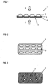
- Figure 2 shows the shape of the carrier substrate 3 provided with the semitransparent functional layer in plan view.
- the carrier substrate 3 is recessed in the areas 8 which correspond to the outline of the cavities of the plastic film molded part 2.
- Figure 3 shows the shape of the opaque cover film 4 in plan view.
- the opaque cover film 4 is left out in the areas 5.
- Figure 4 shows the front of the tablet blister 1, namely the plastic film molding 2, when viewed in incident light. Perforations that may be present are shown with reference number 10.
- the viewer perceives the tablets 9 through the transparent plastic film molded part 2.
- the carrier substrate 3 provided with the semitransparent functional layer in the form of a homogeneous, gold-colored metallization.
- Figure 5 shows the front of the tablet blister 1, namely the plastic film molded part 2, when viewed in transmitted light.
- the viewer perceives the tablets 9 through the transparent plastic film molded part 2.
- the carrier substrate 3 provided with the semitransparent functional layer in the form of a homogeneous, gold-colored metallization, the additional areas 11 shown with hatching being visible in light blue.
- Figure 6 shows the back of the tablet blister 1, namely the opaque, aluminum-based cover film 4 when viewed in incident light.
- the opaque cover film 4 has the shape of a homogeneous, silver metallization, the carrier substrate 3 provided with the semitransparent functional layer being visible in the shape of a gold-colored metallization in the areas of the cutouts 12.
- Figure 7 shows the back of the tablet blister 1, namely the opaque, aluminum-based cover sheet 4 when viewed in transmitted light.
- the opaque cover film 4 has the shape of a homogeneous, silver metallization, the carrier substrate 3 provided with the semitransparent functional layer being visible in light blue in the regions of the cutouts 12.
- Figures 8 to 14 illustrate the functioning of a blister pack according to the invention according to a second embodiment.
- the blister packaging is described in the present example using a tablet blister.
- Figure 8 shows the cross-sectional view of a tablet blister 13 which comprises a transparent plastic film molded part 14 and an opaque cover film 15.
- the block arrow 18 symbolizes the viewing of the tablet blister 13 from the front
- the block arrow 19 symbolizes the viewing of the tablet blister 13 from the rear.
- the opaque cover film 15 is based on an aluminum film provided with a heat seal coating and having a thickness of 20 micrometers.
- the opaque cover film 15 has transparent areas 17, namely recesses created by punching or by laser cutting.
- a carrier substrate 16 namely a polyethylene terephthalate (PET) film, is provided with a semitransparent functional layer.
- PET polyethylene terephthalate
- the carrier substrate 16 provided with a semitransparent functional layer is attached to the opaque cover film 15 by means of an adhesive layer.
- the plastic film molded part 14 has cavities in which tablets (not shown in the figure) are located.
- the semi-transparent functional layer based on the layer sequence 20 nm Ag / 240 nm SiO 2/20 nm Ag and exhibits a gold / blue color change in incident light / transmitted light viewing.
- the semi-transparent functional layer is available by vapor deposition.
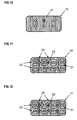
- Figure 9 shows the shape of the carrier substrate 16 provided with the semitransparent functional layer in a top view.
- the carrier substrate 16 is recessed in the regions 20 which correspond to the contour lines of the cavities of the plastic film molded part 14.
- Figure 10 shows the shape of the opaque cover film 15 in plan view.
- the opaque cover film 15 is left in the areas 17.
- Figure 11 shows the front of the tablet blister 13, namely the plastic film molded part 14, when viewed in incident light. Perforations that may be present are shown with reference number 22.
- the viewer perceives the tablets 21 through the transparent plastic film molded part 14.
- the viewer recognizes the opaque cover film 15 in the form of a silver metallization, the carrier substrate 16 arranged below the opaque cover film 15 and provided with the semitransparent functional layer in the form of a gold-colored metallization being visible in the regions of the cutouts 23.
- Figure 12 shows the front of the tablet blister 13, namely the plastic film molded part 14, when viewed in transmitted light.
- the viewer perceives the tablets 21 through the transparent plastic film molded part 14.
- the viewer recognizes the opaque cover film 15 in the form of a silver metallization, the carrier substrate 16 arranged below the opaque cover film 15 and provided with the semitransparent functional layer being visible in light blue in the areas of the recesses 23.
- Figure 13 shows the back of the tablet blister 13, namely the carrier substrate 16 provided with the semi-transparent functional layer, when viewed in incident light.
- the carrier substrate 16 provided with the semitransparent functional layer has the shape of a gold-colored metallization, the opaque cover film 15 being visible in the shape of a silver metallization in the areas of the cutouts 24.
- Figure 14 shows the back of the tablet blister 13, namely the carrier substrate 16 provided with the semitransparent functional layer, when viewed in transmitted light.
- the carrier substrate 16 provided with the semitransparent functional layer has the shape of a gold-colored metallization, the regions 25 appearing in light blue.
- the opaque cover film 15 is visible in the form of a silver metallization.
- a third exemplary embodiment is based on that in FIGS Figures 1 to 7 first embodiment described.
- the shape of the in the Figure 2 shown, provided with the semi-transparent functional layer carrier substrate 3 is modified such that the carrier substrate provided with the semi-transparent functional layer is no longer a single object, but in the form of a plurality, namely in the form of the Figure 15 shown strip 26 is present.
- a fourth exemplary embodiment is based on that in FIGS Figures 8 to 14 second embodiment described.
- the shape of the in the Figure 9 shown, provided with the semi-transparent functional layer carrier substrate 16 is modified, however, in such a way that the carrier substrate provided with the semi-transparent functional layer is no longer a single object, but in the form of a plurality, namely in the form of the Figure 15 shown strip 26 is present.
- a fifth exemplary embodiment is based on that in FIGS Figures 1 to 7 first embodiment described.
- the shape of the in the Figure 2 shown, provided with the semi-transparent functional layer carrier substrate 3 is modified, however, in such a way that the carrier substrate provided with the semi-transparent functional layer no more than a single object, but in the form of a plurality, namely in the form of the Figure 16 Patches or patches 27 shown is present.
- a sixth embodiment is in the in the Figures 8 to 14 second embodiment described.
- the shape of the in the Figure 9 shown, provided with the semi-transparent functional layer carrier substrate 16 is modified, however, in such a way that the carrier substrate provided with the semi-transparent functional layer is no longer a single object, but in the form of a plurality, namely in the form of the Figure 16 Patches or patches 27 shown is present.
Description
Die Erfindung betrifft eine Blisterverpackung, umfassend ein Kunststofffolienformteil, eine Abdeckfolie und eine semitransparente Funktionsschicht, die so beschaffen ist, dass sie bei der Betrachtung im Auflicht eine erste, visuell erkennbare Farbe aufweist und bei der Betrachtung im Durchlicht eine zweite, visuell erkennbare Farbe aufweist. Die Erfindung betrifft des Weiteren eine für das Herstellen der vorstehend genannten Blisterverpackung geeignete Abdeckfolie und ein Verfahren zum Herstellen der vorstehend genannten Blisterverpackung.The invention relates to a blister pack, comprising a plastic film molded part, a cover film and a semi-transparent functional layer, which is designed such that it has a first, visually recognizable color when viewed in incident light and has a second, visually recognizable color when viewed in transmitted light. The invention further relates to a cover film suitable for producing the above-mentioned blister packaging and a method for producing the above-mentioned blister packaging.
Unter einer Blisterverpackung (bzw. Blister, Sichtverpackung) versteht man eine Produktverpackung, die es dem potentiellen Käufer ermöglicht, den verpackten Gegenstand optisch wahrzunehmen oder zumindest die Form des Gegenstandes zu erahnen. Der Gegenstand wird dabei von einem mit einer Abdeckfolie verschlossenen Kunststofffolienformteil fixiert. Bei Medikamenten, z.B. Tabletten, besteht die Abdeckfolie zumeist aus Aluminium. Eine Tablettenverpackung bzw. ein Tablettenblister wird auch Durchdrückpackung genannt. Die Anordnung der Tabletten in einzelnen Vertiefungen bzw. Kavitäten des Kunststofffolienformteils, das durch die Aluminiumfolie versiegelt wird, ist hygienisch von Vorteil, da unerwünschte Einflüsse wie hohe Luftfeuchtigkeit oder Schmutz ausgeschlossen sind.A blister pack (or blister, blister pack) is a product packaging that enables the potential buyer to perceive the packaged item optically or at least to guess the shape of the item. The object is fixed by a plastic film molded part closed with a cover film. For medicines, e.g. Tablets, the cover film is usually made of aluminum. A tablet packaging or a tablet blister is also called a blister pack. The arrangement of the tablets in individual recesses or cavities of the plastic film molded part, which is sealed by the aluminum film, is hygienically advantageous, since undesirable influences such as high air humidity or dirt are excluded.
Die Herstellung von Blistern wird z.B. in der
Die
Der vorliegenden Erfindung liegt die allgemeine Aufgabe zugrunde, die Fälschungssicherheit der Blisterverpackungen des Standes der Technik zu erhöhen.The present invention is based on the general object of increasing the security against forgery of the blister packs of the prior art.
Die Aufgabe wird durch die in den unabhängigen Ansprüchen definierten Merkmalskombinationen gelöst. Weiterbildungen der Erfindung sind Gegenstand der Unteransprüche.The object is achieved by the combinations of features defined in the independent claims. Developments of the invention are the subject of the dependent claims.
-
1. (Erster Aspekt der Erfindung) Blisterverpackung, umfassend ein mit Kavitäten versehenes Kunststofffolienformteil und eine opake Abdeckfolie mit zumindest einem außerhalb der Kavitäten angeordneten transparenten Bereich, wobei das Kunststofffolienformteil die Vorderseite der Blisterverpackung definiert und die opake Abdeckfolie die Rückseite der Blisterverpackung definiert und die Blisterverpackung zusätzlich in einem bestimmten Bereich, der außerhalb des Bereichs der Kavitäten des Kunststofffolienformteils gebildet ist und zumindest den transparenten Bereich der opaken Abdeckfolie überlappend angeordnet ist, eine semitransparente Funktionsschicht aufweist, die so beschaffen ist, dass die Blisterverpackung im transparenten Bereich der opaken Abdeckfolie bei der Betrachtung im Auflicht eine erste, visuell erkennbare Farbe aufweist und bei der Betrachtung im Durchlicht eine zweite, visuell erkennbare Farbe aufweist.
Der transparente Bereich der opaken Abdeckfolie kann insbesondere in Form eines Musters, in Form von Zeichen oder in Form einer Codierung vorliegen.
Das Kunststofffolienformteil weist mehrere Vertiefungen bzw. Kavitäten auf, wobei die Vertiefungen bzw. Kavitäten für die Aufnahme von zu verpackenden Gegenständen, z.B. Tabletten, geeignet sind.
Bei der Blisterverpackung kann der Farbwechsel bei der Betrachtung im Durchlicht einerseits und bei der Betrachtung im Auflicht andererseits besonders gut wahrgenommen werden, wenn das Kunststofffolienformteil transparent ist. Die semitransparente Funktionsschicht ist z.B. mittels Aufdampfen oder drucktechnisch erhältlich. Die semitransparente Funktionsschicht kann einen einschichtigen oder einen mehrschichtigen Aufbau aufweisen. Im Falle eines mehrschichtigen Aufbaus ist es möglich, dass alle Schichten mittels Aufdampfen erzeugt werden; alternativ ist es möglich, dass eine oder mehrere Schichten mittels Aufdampfen erzeugt werden und eine weitere oder mehrere weitere Schichten drucktechnisch erzeugt werden (zum Beispiel zwei mittels Aufdampfen erzeugte semitransparente metallische Schichten und eine dazwischen angeordnete, drucktechnisch erhältliche, auf Nitrocellulose basierende dielektrische Schicht). Des Weiteren kann die semitransparente Funktionsschicht z.B. in Form einer kontinuierlichen Beschichtung vorliegen oder in Form einer diskontinuierlichen, z.B. aus metallischen Pigmenten bzw. Effektpigmenten erzeugten Beschichtung vorliegen. Konkrete Beispiele im Hinblick auf die semitransparente Funktionsschicht sind insbesondere die folgenden Schichtsysteme A), B) C) und D):- A) zwei semitransparente metallische Schichten und eine dazwischen angeordnete dielektrische Schicht;
- B) zwei semitransparente metallische Schichten und eine dazwischen angeordnete, bevorzugt 1 bis 2 Mikrometer dicke, Farbschicht (z.B. in blauer Farbe); bevorzugt sind die beiden semitransparenten metallischen Schichten zusätzlich an der Außenseite jeweils mit einer weiteren, bevorzugt 1 bis 2 Mikrometer dicken, Farbschicht, insbesondere in einer Komplementärfarbe zu der zwischen den metallischen Schichten angeordneten Farbschicht (z.B. in gelber Farbe), beschichtet (auf diese Weise ergibt sich der folgende Schichtaufbau mit einem Gold/Blau-Farbwechsel in Auflicht- bzw. Durchlicht-Ansicht: gelbe Druckschicht - semitransparente metallische Schicht - blaue Druckschicht - semitransparente metallische Schicht - gelbe Druckschicht); des Weiteren ist z.B. das folgende, die Schichten a) bis c) umfassende Schichtsystem möglich: a) gelb eingefärbte, "silberne" Spiegelschicht, erhältlich mittels gelb eingefärbter Metallpigmente, die aus der
WO 2005/051675 A2 WO 2005/051675 A2 - C) das obige Schichtsystem kann alternativ so ausgestaltet werden, dass einige der Schichten auf der Vorderseite eines Trägersubstrats angeordnet sind und einige Schichten auf der Rückseite des Trägersubstrats angeordnet sind; z.B. ist das folgende, die Schichten a) bis f) umfassende Schichtsystem möglich: a) gelbe, bevorzugt 1 bis 2 Mikrometer dicke, Farbschicht, b) semitransparente metallische Schicht (z.B. Aluminium), c) Trägersubstrat (z.B. COC- oder PET-Folie), d) blaue, bevorzugt 1 bis 2 Mikrometer dicke, Farbschicht, e) semitransparente metallische Schicht (z.B. Aluminium), f) gelbe, bevorzugt 1 bis 2 Mikrometer dicke, Farbschicht; des Weiteren ist z.B. das folgende, die Schichten a) bis d) umfassende Schichtsystem möglich: a) gelb eingefärbte, "silberne" Spiegelschicht, erhältlich mittels gelb eingefärbter Metallpigmente, die aus der
WO 2005/051675 A2 WO 2005/051675 A2 - D) die oben unter B) und C) genannten Schichtsysteme können selbstverständlich hinsichtlich der gelben Farbschicht und der blauen Farbschicht dahingehend variiert werden, dass anstelle von Gelb bzw. Blau andere Farben verwendet werden, die insbesondere zueinander komplementär sind.
- PVC (Polyvinylchlorid),
- PVDC (Polyvinylidenchlorid),
- PVC/PVDC-Mehrschichtanordnung,
- PVC/PE/PVDC-Mehrschichtanordnung,
- PVC/ACLAR®-Mehrschichtanordnung,
- PP (Polypropylen),
- PET (Polyester),
- PS (Polystyrol),
- COP (Cycloolefinpolymer),
- COC (Cycloolefin-Copolymer),
- COC/COC-Mehrschichtanordnung,
- PP/COC/PP-Mehrschichtanordnung,
- PP/ COC/ EVOH/ PP-Mehrschichtanordnung,
- PETG/ COC/ PETG-Mehrschichtanordnung,
- PVC/COC/PVC-Mehrschichtanordnung,
- mit PVDC beschichtetes COC,
- PETG/PCTFE-Mehrschichtanordnung,
- PETG/EVOH/PCTFE-Mehrschichtanordnung,
- PVC/PCTFE-Mehrschichtanordnung,
- PVC/PE/PCTFE-Mehrschichtanordnung,
- PVC/PCTFE/PVC-Mehrschichtanordnung, und
- PVC/EVOH/PCTFE- Mehrschichtanordnung.
Die opake Abdeckfolie ist insbesondere eine Durchdrückfolie. Die Folie kann insbesondere eine metallische Folie sein und wird vorzugsweise von den folgenden Materialien gewählt: Aluminium, insbesondere Hart-Aluminium, Weich-Aluminium, Papier-Aluminium-Kombination oder Papier-Polyester-Aluminium-Laminat.
Für das Versiegeln des Kunststofffolienformteils mit der Abdeckfolie kann die Abdeckfolie insbesondere einen Heißsiegellack (bzw. Heißsiegelbindemittel), der gegebenenfalls mittels einer Heißsiegellackgrundierung (bzw. Haftvermittler) auf der Abdeckfolie angeordnet ist, aufweisen. Anstelle der Formulierung "Heißsiegelbindemittel und gegebenenfalls vorhandener Haftvermittler" wird hierin auch der Begriff "Heißsiegelbeschichtung" verwendet. 1. (First aspect of the invention) blister packaging, comprising a plastic film molded part provided with cavities and an opaque cover film with at least one transparent area arranged outside the cavities, the plastic film molded part defining the front side of the blister packaging and the opaque cover film defining the back side of the blister packaging and the blister packaging additionally in a certain area, which is formed outside the area of the cavities of the plastic film molding and at least overlaps the transparent area of the opaque cover film, has a semitransparent functional layer, which is designed so that the blister packaging in the transparent area of the opaque cover film when viewed has a first, visually recognizable color in incident light and, when viewed in transmitted light, has a second, visually recognizable color.
The transparent area of the opaque cover film can be present in particular in the form of a pattern, in the form of characters or in the form of a coding.
The plastic film molded part has a plurality of depressions or cavities, the depressions or cavities being suitable for holding objects to be packaged, for example tablets.
With blister packaging, the color change can be perceived particularly well when viewed in transmitted light on the one hand and when viewed in incident light on the other hand if the plastic film molded part is transparent. The semi-transparent functional layer is available, for example, by vapor deposition or by printing technology. The semitransparent functional layer can have a single-layer or a multilayer structure. In the case of a multilayer structure, it is possible for all layers to be produced by vapor deposition; alternatively, it is possible for one or more layers to be produced by means of vapor deposition and for a further or more additional layers to be produced using printing technology (for example two semitransparent metallic layers produced by means of vapor deposition and a dielectric layer based on nitrocellulose, which is available in terms of printing technology and arranged in between). Furthermore, the semitransparent functional layer can be in the form of a continuous coating, for example, or can be in the form of a discontinuous coating, for example made of metallic pigments or effect pigments. The following layer systems A), B) C) and D) are concrete examples with regard to the semi-transparent functional layer:- A) two semitransparent metallic layers and a dielectric layer arranged between them;
- B) two semitransparent metallic layers and a color layer (preferably in a blue one, preferably 1 to 2 microns thick) arranged between them Colour); the two semitransparent metallic layers are preferably additionally coated on the outside with a further, preferably 1 to 2 micrometer thick, color layer, in particular in a complementary color to the color layer arranged between the metallic layers (for example in yellow color) (resulting in this way the following layer structure with a gold / blue color change in reflected light or transmitted light view: yellow print layer - semi-transparent metallic layer - blue print layer - semi-transparent metallic layer - yellow print layer); furthermore, for example, the following layer system comprising layers a) to c) is possible: a) yellow-colored, "silver" mirror layer, obtainable by means of yellow-colored metal pigments which result from the
WO 2005/051675 A2 WO 2005/051675 A2 - C) the above layer system can alternatively be designed such that some of the layers are arranged on the front side of a carrier substrate and some layers are arranged on the rear side of the carrier substrate; For example, the following layer system comprising layers a) to f) is possible: a) yellow, preferably 1 to 2 micrometer thick, color layer, b) semitransparent metallic layer (eg aluminum), c) carrier substrate (eg COC or PET film), d) blue, preferably 1 to 2 micrometers thick, color layer, e) semi-transparent metallic layer (eg aluminum), f) yellow, preferably 1 to 2 micrometers thick, color layer; furthermore, for example, the following layer system comprising layers a) to d) is possible: a) yellow-colored, "silver" mirror layer, obtainable by means of yellow-colored metal pigments which result from the
WO 2005/051675 A2 WO 2005/051675 A2 - D) the layer systems mentioned above under B) and C) can of course be varied with regard to the yellow color layer and the blue color layer in such a way that other colors are used instead of yellow or blue, which are in particular complementary to one another.
- PVC (polyvinyl chloride),
- PVDC (polyvinylidene chloride),
- PVC / PVDC multilayer arrangement,
- PVC / PE / PVDC multilayer arrangement,
- PVC / ACLAR® multilayer arrangement,
- PP (polypropylene),
- PET (polyester),
- PS (polystyrene),
- COP (cycloolefin polymer),
- COC (cycloolefin copolymer),
- COC / COC multilayer arrangement,
- PP / COC / PP multilayer arrangement,
- PP / COC / EVOH / PP multilayer arrangement,
- PETG / COC / PETG multilayer arrangement,
- PVC / COC / PVC multilayer arrangement,
- COC coated with PVDC,
- PETG / PCTFE multilayer arrangement,
- PETG / EVOH / PCTFE multilayer arrangement,
- PVC / PCTFE multilayer arrangement,
- PVC / PE / PCTFE multilayer arrangement,
- PVC / PCTFE / PVC multilayer arrangement, and
- PVC / EVOH / PCTFE multilayer arrangement.
The opaque cover film is in particular a push-through film. The foil can in particular be a metallic foil and is preferably chosen from the following materials: aluminum, in particular hard aluminum, soft aluminum, paper-aluminum combination or paper-polyester-aluminum laminate.
For the sealing of the plastic film molded part with the cover film, the cover film can, in particular, be a heat seal lacquer (or heat seal binder), which if necessary by means of a Heat seal lacquer primer (or adhesion promoter) is arranged on the cover film. Instead of the phrase "heat seal binder and any adhesion promoter present", the term "heat seal coating" is also used herein. -
2. (Bevorzugte Ausgestaltung) Blisterverpackung nach Absatz 1, wobei die semitransparente Funktionsschicht auf einem Trägersubstrat gebildet ist und das mit der semitransparenten Funktionsschicht versehene Trägersubstrat zwischen dem Kunststofffolienformteil und der opaken Abdeckfolie angeordnet ist.
Das Trägersubstrat ist insbesondere eine Kunststoff-Folie, z.B. eine Polyethylenterephthalat(PET)-Folie oder eine Cycloolefin-Copolymer(COC)-Folie.
Das mit der semitransparenten Funktionsschicht versehene Trägersubstrat kann insbesondere mittels einer Klebschicht auf der opaken Abdeckfolie angeordnet sein. 2. (Preferred embodiment) blister pack according toparagraph 1, wherein the semi-transparent functional layer is formed on a carrier substrate and the carrier substrate provided with the semi-transparent functional layer is arranged between the molded plastic part and the opaque cover film.
The carrier substrate is in particular a plastic film, for example a polyethylene terephthalate (PET) film or a cycloolefin copolymer (COC) film.
The carrier substrate provided with the semi-transparent functional layer can in particular be arranged on the opaque cover film by means of an adhesive layer. -
3. (Bevorzugte Ausgestaltung) Blisterverpackung nach Absatz 1, wobei die semitransparente Funktionsschicht auf einem Trägersubstrat gebildet ist und das mit der semitransparenten Funktionsschicht versehene Trägersubstrat oberhalb der dem Kunststofffolienformteil gegenüberliegenden Seite der opaken Abdeckfolie angeordnet ist.
Das Trägersubstrat ist insbesondere eine Kunststoff-Folie, z.B. eine Polyethylenterephthalat(PET)-Folie oder eine Cycloolefin-Copolymer(COC)-Folie.
Das mit der semitransparenten Funktionsschicht versehene Trägersubstrat kann insbesondere mittels einer Klebschicht auf der opaken Abdeckfolie angeordnet sein. 3. (Preferred embodiment) blister pack according toparagraph 1, wherein the semi-transparent functional layer is formed on a carrier substrate and the carrier substrate provided with the semi-transparent functional layer is arranged above the side of the opaque cover film opposite the plastic film molded part.
The carrier substrate is in particular a plastic film, for example a polyethylene terephthalate (PET) film or a cycloolefin copolymer (COC) film.
The carrier substrate provided with the semi-transparent functional layer can in particular be arranged on the opaque cover film by means of an adhesive layer. -
4. (Bevorzugte Ausgestaltung) Blisterverpackung nach Absatz 1, wobei die semitransparente Funktionsschicht entweder direkt auf dem Kunststofffolienformteil oder innerhalb des Kunststofffolienformteils gebildet ist.
Beispielsweise kann die semitransparente Funktionsschicht drucktechnisch direkt auf dem Kunststofffolienformteil erzeugt sein. Des Weiteren ist es möglich, dass das Kunststofffolienformteil auf einer Mehrschichtanordnung mit zumindest zwei Schichten basiert und die semitransparente Funktionsschicht zwischen den beiden Schichten angeordnet ist, oder das Kunststofffolienformteil auf einer Mehrschichtanordnung mit zumindest einer inneren Schicht und zwei Deckschichten basiert und die semitransparente Funktionsschicht zwischen der inneren Schicht und einer der beiden Deckschichten angeordnet ist, wobei die Mehrschichtanordnung bevorzugt von der Gruppe der folgenden Elemente gewählt ist:- PVC/PVDC-Mehrschichtanordnung,
- PVC/PE/PVDC-Mehrschichtanordnung,
- PVC/ACLAR®-Mehrschichtanordnung,
- COC/COC-Mehrschichtanordnung,
- PP/ COC/ PP-Mehrschichtanordnung,
- PP/ COC/ EVOH/ PP-Mehrschichtanordnung,
- PETG/ COC/ PETG-Mehrschichtanordnung,
- PVC/COC/PVC-Mehrschichtanordnung,
- mit PVDC beschichtetes COC,
- PETG/PCTFE-Mehrschichtanordnung,
- PETG/ EVOH/ PCTFE-Mehrschichtanordnung,
- PVC/PCTFE-Mehrschichtanordnung,
- PVC/ PE/ PCTFE-Mehrschichtanordnung,
- PVC/PCTFE/PVC-Mehrschichtanordnung, und
- PVC/EVOH/PCTFE- Mehrschichtanordnung.
paragraph 1, wherein the semi-transparent functional layer is formed either directly on the plastic film molding or within the plastic film molding.
For example, the semitransparent functional layer can be produced directly on the molded plastic part. Furthermore, it is possible that the plastic film molded part is based on a multi-layer arrangement with at least two layers and the semi-transparent functional layer is arranged between the two layers, or that the plastic film molded part is based on a multi-layer arrangement with at least one inner layer and two cover layers and the semi-transparent functional layer between the inner one Layer and one of the two cover layers is arranged, wherein the multilayer arrangement is preferably selected from the group of the following elements:- PVC / PVDC multilayer arrangement,
- PVC / PE / PVDC multilayer arrangement,
- PVC / ACLAR® multilayer arrangement,
- COC / COC multilayer arrangement,
- PP / COC / PP multilayer arrangement,
- PP / COC / EVOH / PP multilayer arrangement,
- PETG / COC / PETG multilayer arrangement,
- PVC / COC / PVC multilayer arrangement,
- COC coated with PVDC,
- PETG / PCTFE multilayer arrangement,
- PETG / EVOH / PCTFE multilayer arrangement,
- PVC / PCTFE multilayer arrangement,
- PVC / PE / PCTFE multilayer arrangement,
- PVC / PCTFE / PVC multilayer arrangement, and
- PVC / EVOH / PCTFE multilayer arrangement.
-
5. (Bevorzugte Ausgestaltung) Blisterverpackung nach einem der Absätze 1 bis 4, wobei die semitransparente Funktionsschicht einen mehrschichtigen Aufbau mit zwei semitransparenten metallischen Schichten und einer zwischen den zwei semitransparenten metallischen Schichten angeordneten dielektrischen Schicht aufweist.5. (Preferred embodiment) blister packaging according to one of
paragraphs 1 to 4, the semi-transparent functional layer having a multilayer structure with two semi-transparent metallic layers and a dielectric layer arranged between the two semi-transparent metallic layers. -
6. (Bevorzugte Ausgestaltung) Blisterverpackung nach Absatz 5, wobei die beiden semitransparenten metallischen Schichten unabhängig voneinander aus einem Metall gebildet sind und das Metall jeweils von der Gruppe bestehend aus Al, Ag, Ni, Cr, Cu, Au und einer Legierung eines oder mehrerer der vorstehend genannten Elemente gewählt ist und die dielektrische Schicht eine SiO2-Schicht, eine ZnO-Schicht, eine Al2O3-Schicht, eine TiO2-Schicht, eine Schicht aus einem Nitrid oder Oxynitrid eines der Elemente Si, Zn, Al oder Ti oder eine MgF2-Schicht oder eine, z.B. drucktechnisch erhältliche, Nitrocellulose-Schicht ist.6. (Preferred embodiment) blister pack according to
paragraph 5, wherein the two semi-transparent metallic layers are formed independently of one another from a metal and the metal in each case from the group consisting of Al, Ag, Ni, Cr, Cu, Au and an alloy of one or more of the above-mentioned elements is selected and the dielectric layer is an SiO 2 layer, a ZnO layer, an Al 2 O 3 layer, a TiO 2 layer, a layer made of a nitride or oxynitride of one of the elements Si, Zn, Al or Ti or a MgF 2 layer or a nitrocellulose layer, for example obtainable by printing technology. -
7. (Bevorzugte Ausgestaltung) Blisterverpackung nach Absatz 6, wobei die beiden semitransparenten metallischen Schichten von Al oder Ag gewählt sind und die dielektrische Schicht eine SiO2-Schicht ist.7. (Preferred embodiment) blister packaging according to
paragraph 6, the two semi-transparent metallic layers of Al or Ag being chosen and the dielectric layer being an SiO 2 layer. -
8. (Bevorzugte Ausgestaltung) Blisterverpackung nach einem der Absätze 5 bis 7, wobei die Blisterverpackung im transparenten Bereich der opaken Abdeckfolie bei der Betrachtung im Auflicht goldfarben erscheint und bei der Betrachtung im Durchlicht einen blauen Farbton aufweist.8. (Preferred embodiment) blister packaging according to one of
paragraphs 5 to 7, the blister packaging in the transparent area of the opaque cover film appearing gold-colored when viewed in incident light and has a blue hue when viewed in transmitted light. -
9. (Bevorzugte Ausgestaltung) Blisterverpackung nach einem der Absätze 1 bis 4, wobei die semitransparente Funktionsschicht drucktechnisch mittels einer Effektpigment-Zusammensetzung erhältlich ist.9. (Preferred embodiment) blister packaging according to one of the
paragraphs 1 to 4, the semi-transparent functional layer being obtainable in terms of printing technology by means of an effect pigment composition. -
10. (Bevorzugte Ausgestaltung) Blisterverpackung nach einem der Absätze 1 bis 9, wobei die opake Abdeckfolie eine metallische Folie, insbesondere eine Aluminiumfolie, ist und der transparente Bereich der opaken Abdeckfolie in Form einer Aussparung in der opaken Abdeckfolie gebildet ist.
Die Aussparung kann insbesondere mittels Stanzen oder mittels Laser-Schneiden erzeugt sein. 10. (Preferred embodiment) blister pack according to one ofparagraphs 1 to 9, the opaque cover film being a metallic film, in particular an aluminum film, and the transparent region of the opaque cover film being formed in the form of a recess in the opaque cover film.
The recess can be created in particular by means of punching or by means of laser cutting. -
11. (Bevorzugte Ausgestaltung) Blisterverpackung nach einem der Absätze 1 bis 10, wobei die Blisterverpackung ein Blister für Pharmaerzeugnisse, insbesondere ein Tablettenblister ist.11. (Preferred embodiment) blister pack according to one of
paragraphs 1 to 10, the blister pack being a blister pack for pharmaceutical products, in particular a tablet blister pack. -
12. (Zweiter Aspekt der Erfindung) Abdeckfolie, geeignet für das Abdecken eines Kunststofffolienformteils einer Blisterverpackung, wobei die Abdeckfolie opak ist und zumindest einen transparenten Bereich aufweist und in einem bestimmten Bereich, der so angepasst ist, dass er außerhalb des Bereichs der Kavitäten des Kunststofffolienformteils gebildet ist und zumindest den transparenten Bereich der opaken Abdeckfolie überlappend angeordnet ist, eine semitransparente Funktionsschicht aufweist, die so beschaffen ist, dass die Abdeckfolie im transparenten Bereich bei der Betrachtung im Auflicht eine erste, visuell erkennbare Farbe aufweist und bei der Betrachtung im Durchlicht eine zweite, visuell erkennbare Farbe aufweist.
Für das Versiegeln eines Kunststofffolienformteils mit der Abdeckfolie kann die Abdeckfolie insbesondere einen Heißsiegellack (bzw. Heißsiegelbindemittel), der gegebenenfalls mittels einer Heißsiegellackgrundierung (bzw. Haftvermittler) auf der Abdeckfolie angeordnet ist, aufweisen. Anstelle der Formulierung "Heißsiegelbindemittel und gegebenenfalls vorhandener Haftvermittler" wird hierin auch der Begriff "Heißsiegelbeschichtung" verwendet.
Die opake Abdeckfolie ist insbesondere eine Durchdrückfolie. Die Folie kann insbesondere eine metallische Folie sein und weiter im Besonderen von den folgenden Materialien gewählt werden: Aluminium, insbesondere Hart-Aluminium, Weich-Aluminium, Papier-Aluminium-Kombination oder Papier-Polyester-Aluminium-Laminat. 12. (Second aspect of the invention) cover film, suitable for covering a plastic film molded part of a blister pack, the cover film being opaque and having at least one transparent region and in a specific region which is adapted to be outside the region of the cavities of the plastic film molded part is formed and at least the transparent area of the opaque cover film is arranged to overlap, has a semitransparent functional layer which is designed such that the cover film in the transparent area at the Viewing in incident light has a first, visually recognizable color and, when viewed in transmitted light, has a second, visually recognizable color.
For the sealing of a plastic film molded part with the cover film, the cover film can in particular have a heat seal lacquer (or heat seal binder), which is optionally arranged on the cover film by means of a heat seal lacquer primer (or adhesion promoter). Instead of the phrase "heat seal binder and any adhesion promoter present", the term "heat seal coating" is also used herein.
The opaque cover film is in particular a push-through film. The foil can in particular be a metallic foil and can also be selected in particular from the following materials: aluminum, in particular hard aluminum, soft aluminum, paper-aluminum combination or paper-polyester-aluminum laminate. -
13. (Bevorzugte Ausgestaltung) Abdeckfolie nach Absatz 12, wobei die semitransparente Funktionsschicht auf einem Trägersubstrat, z.B. eine Kunststoff-Folie, gebildet ist und das mit der semitransparenten Funktionsschicht versehene Trägersubstrat oberhalb der opaken Abdeckfolie angeordnet ist.13. (Preferred embodiment) cover film according to
paragraph 12, wherein the semi-transparent functional layer on a carrier substrate, e.g. a plastic film is formed and the carrier substrate provided with the semi-transparent functional layer is arranged above the opaque cover film. -
14. (Bevorzugte Ausgestaltung) Abdeckfolie nach einem der Absätze 12 oder 13, wobei die semitransparente Funktionsschicht einen mehrschichtigen Aufbau mit zwei semitransparenten metallischen Schichten und einer zwischen den zwei semitransparenten metallischen Schichten angeordneten dielektrischen Schicht aufweist.14. (Preferred embodiment) covering film according to one of the
paragraphs -
15. (Bevorzugte Ausgestaltung) Abdeckfolie nach Absatz 14, wobei die beiden semitransparenten metallischen Schichten unabhängig voneinander aus einem Metall gebildet sind und das Metall jeweils von der Gruppe bestehend aus Al, Ag, Ni, Cr, Cu, Au und einer Legierung eines oder mehrerer der vorstehend genannten Elemente gewählt ist und die dielektrische Schicht eine SiO2-Schicht, eine ZnO-Schicht, eine Al2O3-Schicht, eine TiO2-Schicht, eine Schicht aus einem Nitrid oder Oxynitrid eines der Elemente Si, Zn, Al oder Ti oder eine MgF2-Schicht oder eine, z.B. drucktechnisch erhältliche, Nitrocellulose-Schicht ist.15. (Preferred embodiment) cover film according to
paragraph 14, wherein the two semi-transparent metallic layers are formed independently of one another from a metal and the metal in each case from the group consisting of Al, Ag, Ni, Cr, Cu, Au and an alloy of one or more of the above-mentioned elements is selected and the dielectric layer is an SiO 2 layer, a ZnO layer, an Al 2 O 3 layer, a TiO 2 layer, a layer made of a nitride or oxynitride of one of the elements Si, Zn, Al or Ti or a MgF 2 layer or a nitrocellulose layer, for example obtainable by printing technology. -
16. (Bevorzugte Ausgestaltung) Abdeckfolie nach Absatz 15, wobei die beiden semitransparenten metallischen Schichten von Al oder Ag gewählt sind und die dielektrische Schicht eine SiO2-Schicht ist.16. (Preferred embodiment) cover film according to
paragraph 15, wherein the two semi-transparent metallic layers of Al or Ag are selected and the dielectric layer is an SiO 2 layer. -
17. (Bevorzugte Ausgestaltung) Abdeckfolie nach einem der Absätze 14 bis 16, wobei die Abdeckfolie im transparenten Bereich bei der Betrachtung im Auflicht goldfarben erscheint und bei der Betrachtung im Durchlicht einen blauen Farbton aufweist.17. (Preferred embodiment) cover film according to one of
paragraphs 14 to 16, the cover film appearing gold-colored in the transparent area when viewed in incident light and has a blue hue when viewed in transmitted light. -
18. (Bevorzugte Ausgestaltung) Abdeckfolie nach einem der Absätze 12 oder 13, wobei die semitransparente Funktionsschicht drucktechnisch mittels einer Effektpigment-Zusammensetzung erhältlich ist.18. (Preferred embodiment) cover film according to one of the
paragraphs -
19. (Bevorzugte Ausgestaltung) Abdeckfolie nach einem der Absätze 13 bis 18, wobei das oberhalb der opaken Abdeckfolie angeordnete, mit der semitransparenten Funktionsschicht versehene Trägersubstrat die Gestalt einer Mehrzahl von Streifen oder Patches bzw. Flicken hat.19. (Preferred embodiment) cover film according to one of
paragraphs 13 to 18, wherein the carrier substrate arranged above the opaque cover film and provided with the semi-transparent functional layer has the shape of a plurality of strips or patches or patches. -
20. (Bevorzugte Ausgestaltung) Abdeckfolie nach einem der Absätze 12 bis 19, wobei die Abdeckfolie eine metallische Folie, insbesondere eine Aluminiumfolie, ist und der transparente Bereich der opaken Abdeckfolie in Form einer Aussparung in der opaken Abdeckfolie gebildet ist.20. (Preferred embodiment) cover film according to one of
paragraphs 12 to 19, the cover film being a metallic film, in particular an aluminum film, and the transparent area of the opaque cover film being formed in the form of a recess in the opaque cover film. -
21. (Bevorzugte Ausgestaltung) Abdeckfolie nach einem der Absätze 12 bis 20, geeignet für das Herstellen einer Blisterverpackung nach einem der Absätze 1 bis 3 oder nach einem der auf die Absätze 1 bis 3 rückbezogenen Absätze 5 bis 11.21. (Preferred embodiment) covering film according to one of
paragraphs 12 to 20, suitable for producing a blister pack according to one ofparagraphs 1 to 3 or according to one of theparagraphs 5 to 11 referring toparagraphs 1 to 3. -
22. (Dritter Aspekt der Erfindung) Verfahren zum Herstellen einer Blisterverpackung, umfassend den Schritt des Abdeckens eines mit Kavitäten versehenen Kunststofffolienformteils mit einer Abdeckfolie nach einem der Absätze 12 bis 21.22. (Third aspect of the invention) A method for producing a blister pack, comprising the step of covering a molded plastic film part provided with cavities with a cover film according to one of the
paragraphs 12 to 21.
In der Beschreibung werden die Begriffe "Kunststofffolienformteil" und "Kunststoffformfolie" als Synonyme verwendet.In the description, the terms "plastic film molded part" and "plastic molded film" are used as synonyms.
Die Vorderseite der erfindungsgemäßen Blisterverpackung wird durch das Kunststofffolienformteil definiert. Die Rückseite der erfindungsgemäßen Blisterverpackung wird durch die Abdeckfolie definiert.The front of the blister pack according to the invention is defined by the plastic film molded part. The back of the blister pack according to the invention is defined by the cover film.
Eine Betrachtung im Auflicht ist im Sinne dieser Erfindung eine Beleuchtung des jeweiligen Gegenstandes von einer Seite und eine Betrachtung des Gegenstandes von derselben Seite. Eine Betrachtung im Auflicht liegt somit beispielsweise dann vor, wenn die Vorderseite des Blisters beleuchtet und auch betrachtet wird.For the purposes of this invention, viewing in incident light is lighting the respective object from one side and viewing the object from the same side. An observation in incident light is thus, for example, when the front of the blister is illuminated and also viewed.
Eine Betrachtung im Durchlicht ist im Sinne dieser Erfindung eine Beleuchtung des jeweiligen Gegenstandes von einer Seite und eine Betrachtung des Gegenstandes von der gegenüberliegenden Seite. Eine Betrachtung im Durchlicht liegt somit beispielsweise dann vor, wenn die Rückseite des Blisters beleuchtet und die Vorderseite des Blisters betrachtet wird. Das Licht scheint somit mindestens teilweise durch die Verpackung hindurch.For the purposes of this invention, viewing in transmitted light is lighting the respective object from one side and viewing the object from the opposite side. An observation in transmitted light is thus, for example, when the back of the blister is illuminated and the front of the blister is viewed. The light shines at least partially through the packaging.
Die erfindungsgemäße Blisterverpackung zeichnet sich dadurch aus, dass sie einen semitransparenten Bereich mit einem Farbwechsel bei der Betrachtung im Auflicht (Reflexion) einerseits und bei der Betrachtung im Durchlicht (Transmission) andererseits aufweist. Der Farbwechsel ist ohne technische Hilfsmittel mit dem bloßen Auge überprüfbar und dient der Echtheitskontrolle der Blisterverpackung. Die Echtheitskontrolle kann z.B. vor dem erstmaligen Konsumieren der im Blister enthaltenen (Pharma-)Erzeugnisse, z.B. Tabletten, vorgenommen werden.The blister packaging according to the invention is characterized in that it has a semi-transparent area with a color change when viewed in incident light (reflection) on the one hand and when viewed in transmitted light (transmission) on the other hand. The color change can be checked with the naked eye without technical aids and serves to check the authenticity of the blister packaging. The authenticity check can e.g. before the first consumption of the (pharmaceutical) products contained in the blister, e.g. Tablets.
Die erfindungsgemäße Blisterverpackung ist infolge ihrer erhöhten Fälschungssicherheit besonders vorteilhaft, da semitransparente Blisterverpackungen mit Farbwechsel bei der Betrachtung im Auflicht einerseits und bei der Betrachtung im Durchlicht andererseits für den Fälscher verhältnismäßig schwer zugänglich sind. Darüber hinaus ist eine unkomplizierte Echtheitsprüfung der erfindungsgemäßen Blisterverpackung durch den Konsumenten, auch im Falle eines Kindes, durch das Betrachten der Blisterverpackung mit Blick auf das Kunststofffolienformteil und/oder mit Blick auf die Abdeckfolie im Auflicht und im Durchlicht ohne zusätzliche technische Hilfsmittel durchführbar.The blister packaging according to the invention is particularly advantageous due to its increased protection against counterfeiting, since semi-transparent blister packs with color changes are relatively difficult to access for the counterfeiter when viewed in incident light on the one hand and when viewed in transmitted light on the other hand. In addition, an uncomplicated authenticity check of the blister packaging according to the invention can be carried out by the consumer, even in the case of a child, by looking at the blister packaging with a view of the plastic film molded part and / or with a view of the cover film in incident light and in transmitted light without additional technical aids.
Zur Erhöhung des Fälschungsschutzes können die Abdeckfolie oder das Kunststofffolienformteil mit zusätzlichen Fälschungssicherungsmitteln ausgestattet werden, z.B.
- die Bereitstellung einer zusätzlichen opaken Beschichtung, insbesondere eine Druckschicht oder eine Metallisierung, die Aussparungen in Form von Mustern, Zeichen oder einer Codierung aufweist;
- das Bedrucken mit (Mikro-)Schrift, insbesondere mit Effektpigmenten;
- das Bereitstellen lumineszierender oder magnetischer Sicherheitsmerkmale, die insbesondere maschinell erfassbar sind;
- das Bereitstellen eines zusätzlichen Hologramms, insbesondere eine Prägelackschicht mit einer diffraktiven Reliefstruktur, die ggf. mit einer Metallisierung versehen ist;
- das Bereitstellen einer mikrooptischen Reliefstruktur, insbesondere einer Mikrospiegel-Anordnung; die Herstellung einer mikrooptischen Reliefstruktur ist im Stand der Technik bekannt (siehe z.B. die
WO 2014/060089 A2
- the provision of an additional opaque coating, in particular a printing layer or a metallization, which has cutouts in the form of patterns, characters or a coding;
- printing with (micro) writing, especially with effect pigments;
- the provision of luminescent or magnetic security features, which are in particular machine-detectable;
- the provision of an additional hologram, in particular an embossing lacquer layer with a diffractive relief structure, which is optionally provided with a metallization;
- the provision of a micro-optical relief structure, in particular a micromirror arrangement; the production of a micro-optical relief structure is known in the prior art (see, for example, the
WO 2014/060089 A2
Das Kunststofffolienformteil ist insbesondere transparent und beruht z.B. auf einem der folgenden Materialien, die jeweils als eine einzelne Schicht oder in Form mehrerer Schichten vorliegen können:
- PVC (Polyvinylchlorid),
- PVDC (Polyvinylidenchlorid),
- PVC/PVDC-Mehrschichtanordnung,
- PVC/PE/ PVDC-Mehrschichtanordnung,
- PVC/ACLAR®-Mehrschichtanordnung,
- PP (Polypropylen),
- PET (Polyester),
- PS (Polystyrol),
- COP (Cycloolefinpolymer),
- COC (Cycloolefin-Copolymer),
- COC/COC-Mehrschichtanordnung,
- PP/ COC/PP-Mehrschichtanordnung,
- PP/COC/EVOH/PP-Mehrschichtanordnung,
- PETG/ COC/ PETG-Mehrschichtanordnung,
- PVC/COC/PVC-Mehrschichtanordnung,
- mit PVDC beschichtetes COC,
- PETG/PCTFE-Mehrschichtanordnung,
- PETG/ EVOH/ PCTFE-Mehrschichtanordnung,
- PVC/PCTFE-Mehrschichtanordnung,
- PVC/PE/PCTFE-Mehrschichtanordnung,
- PVC/PCTFE/PVC-Mehrschichtanordnung, und
- PVC/EVOH/PCTFE- Mehrschichtanordnung.
- PVC (polyvinyl chloride),
- PVDC (polyvinylidene chloride),
- PVC / PVDC multilayer arrangement,
- PVC / PE / PVDC multilayer arrangement,
- PVC / ACLAR® multilayer arrangement,
- PP (polypropylene),
- PET (polyester),
- PS (polystyrene),
- COP (cycloolefin polymer),
- COC (cycloolefin copolymer),
- COC / COC multilayer arrangement,
- PP / COC / PP multilayer arrangement,
- PP / COC / EVOH / PP multilayer arrangement,
- PETG / COC / PETG multilayer arrangement,
- PVC / COC / PVC multilayer arrangement,
- COC coated with PVDC,
- PETG / PCTFE multilayer arrangement,
- PETG / EVOH / PCTFE multilayer arrangement,
- PVC / PCTFE multilayer arrangement,
- PVC / PE / PCTFE multilayer arrangement,
- PVC / PCTFE / PVC multilayer arrangement, and
- PVC / EVOH / PCTFE multilayer arrangement.
Im Falle, dass das transparente Trägersubstrat des Kunststofffolienformteils auf einer Mehrschichtanordnung basiert, können zwei einzelne Schichten insbesondere mittels einer Klebschicht miteinander verbunden sein (z.B. PVDC/Klebschicht/PVC-Aufbau, PVDC/ Klebschicht/ PE/ Klebschicht/ PVC-Aufbau oder PP/Klebschicht/COC/Klebschicht/PP-Aufbau). Anstelle einer Klebschicht kann für das verbesserte Verbinden zweier einzelner Schichten einer Mehrschichtanordnung eine polymere Heißsiegelschicht verwendet werden, die z.B. mittels Coextrusion erhältlich ist. Als polymere Heißsiegelschicht ist z.B. Polyethylen-Copolymer geeignet.In the event that the transparent carrier substrate of the plastic film molding is based on a multilayer arrangement, two individual layers can be connected to one another in particular by means of an adhesive layer (e.g. PVDC / adhesive layer / PVC structure, PVDC / adhesive layer / PE / adhesive layer / PVC structure or PP / adhesive layer / COC / adhesive layer / PP structure). Instead of an adhesive layer, a polymeric heat seal layer can be used for the improved connection of two individual layers of a multilayer arrangement, which e.g. is available by means of coextrusion. The polymeric heat seal layer is e.g. Polyethylene copolymer suitable.
Das Kunststofffolienformteil kann z.B. eine Materialdicke im Bereich von 100 Mikrometer bis 600 Mikrometer aufweisen, wobei der Bereich von 200 Mikrometer bis 500 Mikrometer bevorzugt wird.The plastic film molded part can, for example, have a material thickness in the range from 100 micrometers to 600 micrometers, the range from 200 micrometers to 500 micrometers being preferred.
Die semitransparente Funktionsschicht weist bei der Betrachtung im Auflicht einerseits und bei der Betrachtung im Durchlicht andererseits unterschiedliche Farbtöne auf. Die beiden unterschiedlichen Farbtöne sind z.B. Komplementärfarben. Eine solche semitransparente Funktionsschicht beruht z.B. auf einem mehrschichtigen Aufbau mit zwei semitransparenten metallischen Schichten und einer zwischen den zwei semitransparenten metallischen Schichten angeordneten dielektrischen Schicht. Ein solcher mehrschichtiger Aufbau, der bei der Betrachtung im Auflicht goldfarben erscheint und bei der Betrachtung im Durchlicht einen blauen Farbton zeigt, ist z.B. aus der
Geeignete mehrschichtige Aufbauten mit zwei semitransparenten metallischen Schichten und einer zwischen den zwei semitransparenten metallischen Schichten angeordneten dielektrischen Schicht haben vorzugsweise die folgende gegenständliche Beschaffenheit:
- die beiden semitransparenten metallischen Schichten werden bevorzugt von Al oder Ag gewählt; die dielektrische Schicht ist insbesondere eine SiO2-Schicht oder eine MgF2-Schicht, bevorzugt eine SiO2-Schicht;
- im Falle, dass jede der beiden semitransparenten metallischen Schichten auf Al beruht, liegt die jeweilige bevorzugte Schichtdicke in einem
Bereich von 5nm bis 20 nm, insbesondere bevorzugt in einemBereich von 10nm bis 14 nm; die dielektrische SiO2-Schicht hat vorzugsweise eine Schichtdicke in einem Bereich von 50 nm bis 450 nm, weiter bevorzugt in einem Bereich von 80 nm bis 260 nm und insbesondere bevorzugt in einem Bereich von 210 nm bis 260 nm, wobei die Bereiche von 80 nm bis 100 nm und von 210 nm bis 240 nm speziell für die Bereitstellung eines Gold/Blau-Farbwechsels besonders bevorzugt werden; - im Falle, dass jede der beiden semitransparenten metallischen Schichten auf Ag beruht, liegt die jeweilige bevorzugte Schichtdicke in einem
Bereich von 15 nm bis 30 nm, insbesondere bevorzugtvon 15nm bis 25 nm; die dielektrische SiO2-Schicht hat vorzugsweise eine Schichtdicke in einem Bereich von 50 nm bis 450 nm, weiter bevorzugt in einem Bereich von 80 nm bis 260 nm und insbesondere bevorzugt in einem Bereich von 210 nm bis 260 nm, wobei die Bereiche von 80 nm bis 100 nm und von 210 nm bis 240 nm speziell für die Bereitstellung eines Gold/Blau-Farbwechsels besonders bevorzugt werden.
Suitable multilayer structures with two semitransparent metallic layers and a dielectric layer arranged between the two semitransparent metallic layers preferably have the following physical properties:
- the two semitransparent metallic layers are preferably selected from Al or Ag; the dielectric layer is in particular an SiO 2 layer or an MgF 2 layer, preferably an SiO 2 layer;
- in the event that each of the two semitransparent metallic layers is based on Al, the respective preferred layer thickness is in a range from 5 nm to 20 nm, particularly preferably in a range from 10 nm to 14 nm; the dielectric SiO 2 layer preferably has a layer thickness in a range from 50 nm to 450 nm, more preferably in a range from 80 nm to 260 nm and particularly preferably in a range from 210 nm to 260 nm, the ranges from 80 nm up to 100 nm and from 210 nm to 240 nm are particularly preferred for the provision of a gold / blue color change;
- in the event that each of the two semitransparent metallic layers is based on Ag, the respective preferred layer thickness is in a range from 15 nm to 30 nm, particularly preferably from 15 nm to 25 nm; the dielectric SiO 2 layer preferably has a layer thickness in a range from 50 nm to 450 nm, more preferably in a range from 80 nm to 260 nm and particularly preferably in a range from 210 nm to 260 nm, the ranges from 80 nm up to 100 nm and from 210 nm to 240 nm are particularly preferred for the provision of a gold / blue color change.
Die oben genannten mehrschichtigen Aufbauten mit zwei semitransparenten metallischen Schichten und einer zwischen den zwei semitransparenten metallischen Schichten angeordneten dielektrischen Schicht können einen symmetrischen Dreischichtaufbau aufweisen, bei dem sowohl das Material, als auch die Schichtdicke der beiden semitransparenten metallischen Schichten identisch sind. Alternativ kann aber auch ein asymmetrischer Dreischichtaufbau vorliegen, bei dem das Material und/oder die Schichtdicke der beiden semitransparenten metallischen Schichten unterschiedlich sind, z.B.
- ein Silber/Dielektrikum/Aluminium-Schichtsystem, wobei die Schichtdicken der Silber-Schicht und der Aluminium-Schicht identisch oder verschieden sind;
- ein Silber/Dielektrikum/Silber-Schichtsystem, wobei die Schichtdicken der beiden Silber-Schichten verschieden sind;
- ein Aluminium/Dielektrikum/Aluminium-Schichtsystem, wobei die Schichtdicken der beiden Aluminium-Schichten verschieden sind.
- a silver / dielectric / aluminum layer system, the layer thicknesses of the silver layer and the aluminum layer being identical or different;
- a silver / dielectric / silver layer system, the layer thicknesses of the two silver layers being different;
- an aluminum / dielectric / aluminum layer system, the layer thicknesses of the two aluminum layers being different.
Die oben genannten mehrschichtigen Schichtaufbauten ermöglichen nicht nur die Erzeugung einer semitransparenten Funktionsschicht, die bei Betrachtung im Auflicht goldfarben erscheint und bei der Betrachtung im Durchlicht einen blauen Farbton zeigt, sondern es können je nach Wahl der Schichtdicke insbesondere der dielektrischen Schicht weitere Farbwechsel erzeugt werden, z.B.
- im Auflicht Magenta, im Durchlicht Blau-Grün;
- im Auflicht Türkis, im Durchlicht Orange-Gelb;
- im Auflicht Gold, im Durchlicht Blau-Violett;
- im Auflicht Silber, im Durchlicht Violett.
- magenta in reflected light, blue-green in transmitted light;
- in reflected light turquoise, in transmitted light orange-yellow;
- gold in incident light, blue-violet in transmitted light;
- silver in incident light, violet in transmitted light.
Die verschiedenen, oben genannten Farbwechsel kann ein Pharmahersteller zur Bereitstellung seiner Arzneimittel in Form verschiedener Tablettenverpackungen gemäß einer definierten Farbcodierung nutzen, wobei z.B. die folgende Farbcodierung denkbar ist:
- Kopfschmerztabletten: Tablettenverpackung mit einem semitransparenten Bereich, der im Auflicht goldfarben und im Durchlicht blau erscheint;
- Tabletten gegen Magenschmerzen: Tablettenverpackung mit einem semitransparenten Bereich, der im Auflicht Türkis und im Durchlicht Orange-Gelb erscheint;
- Schlaftabletten: Tablettenverpackung mit einem semitransparenten Bereich, der im Auflicht Magenta und im Durchlicht Blau-Grün erscheint.
- Headache tablets: tablet packaging with a semi-transparent area that appears golden in reflected light and blue in transmitted light;
- Tablets for stomach pain: tablet packaging with a semi-transparent area that appears in turquoise incident light and orange-yellow in transmitted light;
- Sleeping tablets: tablet packaging with a semi-transparent area that appears magenta in transmitted light and blue-green in transmitted light.
Die obige Farbcodierung ermöglicht dem Konsumenten, im Falle einer Bewusstseinsstörung z.B. die versehentliche Einnahme von Tabletten gegen Magenschmerzen anstelle von Kopfschmerztabletten zu vermeiden.The above color coding enables the consumer, in the case of a consciousness disorder e.g. Avoid accidentally taking stomach pain tablets instead of headache tablets.
Eine semitransparente Funktionsschicht, die bei der Betrachtung im Auflicht einerseits und bei der Betrachtung im Durchlicht andererseits unterschiedliche Farbtöne aufweist, kann des Weiteren auf einer Effektpigment-Zusammensetzung basieren. Druckschichten auf Basis einer Effektpigment-Zusammensetzung, die bei der Betrachtung im Auflicht eine andere Farbe wie bei der Betrachtung im Durchlicht zeigt, insbesondere einen Gold/Blau-Farbwechsel, einen Gold/Violett-Farbwechsel, einen Grün-Gold/Magenta-Farbwechsel, einen Violett/Grün-Farbwechsel oder einen Silber/Opak-Farbwechsel, werden z.B. in der
Die verschiedenen, oben genannten Farbwechsel kann ein Pharmahersteller zur Bereitstellung seiner Arzneimittel in Form verschiedener Tablettenverpackungen gemäß einer definierten Farbcodierung nutzen, wobei z.B. die folgende Farbcodierung denkbar ist:
- Kopfschmerztabletten: Tablettenverpackung mit einem semitransparenten Bereich, der im Auflicht goldfarben und im Durchlicht blau erscheint;
- Tabletten gegen Magenschmerzen: Tablettenverpackung mit einem semitransparenten Bereich, der im Auflicht grün-gold und im Durchlicht magenta erscheint;
- Schlaftabletten: Tablettenverpackung mit einem semitransparenten Bereich, der im Auflicht violett und im Durchlicht grün erscheint.
- Headache tablets: tablet packaging with a semi-transparent area that appears golden in reflected light and blue in transmitted light;
- Tablets for stomach pain: tablet packaging with a semi-transparent area that appears green-gold in reflected light and magenta in transmitted light;
- Sleeping pills: tablet packaging with a semi-transparent area that appears violet in reflected light and green in transmitted light.
Die obige Farbcodierung ermöglicht dem Konsumenten, im Falle einer Bewusstseinsstörung z.B. die versehentliche Einnahme von Tabletten gegen Magenschmerzen anstelle von Kopfschmerztabletten zu vermeiden.The above color coding enables the consumer, in the case of a consciousness disorder e.g. Avoid accidentally taking stomach pain tablets instead of headache tablets.
Eine semitransparente Funktionsschicht, die bei der Betrachtung im Auflicht einerseits und bei der Betrachtung im Durchlicht andererseits unterschiedliche Farbtöne aufweist, kann des Weiteren zumindest teilweise auf der Verwendung von konventionellen Farbschichten bzw. Farblacken basieren und gemäß einer der folgenden Varianten beschaffen sein:
- 1) zwei semitransparente metallische Schichten (z.B. 5
nm bis 15 nm Al) und eine dazwischen angeordnete,bevorzugt 1bis 2 Mikrometer dicke, Farbschicht (z.B. in blauer Farbe); bevorzugt sind die beiden semitransparenten metallischen Schichten zusätzlich an der Außenseite jeweils mit einer weiteren,bevorzugt 1bis 2 Mikrometer dicken, Farbschicht, insbesondere in einer Komplementärfarbe zu der zwischen den metallischen Schichten angeordneten Farbschicht (z.B. in gelber Farbe), beschichtet (auf diese Weise ergibt sich der folgende Schichtaufbau mit einem Gold/Blau-Farbwechsel in Auflicht- bzw. Durchlicht-Ansicht: gelbe Druckschicht - semitransparente metallische Schicht - blaue Druckschicht - semitransparente metallische Schicht - gelbe Druckschicht); des Weiteren ist z.B. das folgende, die Schichten a) bis c) umfassende Schichtsystem möglich: a) gelb eingefärbte, "silberne" Spiegelschicht, erhältlich mittels gelb eingefärbter Metallpigmente, die aus derWO 2005/051675 A2 Bereich von 8bis 15 µm, weiter bevorzugt in einem Bereich von 9bis 10 µm liegt, gemessen mit einem Coulter LS130 Laserdiffraktionsgranulometer; eine solche Druckfarbe ermöglicht die Bereitstellung einer "silbernen" Spiegelschicht), b) blaue,bevorzugt 1bis 2 Mikrometer dicke, Farbschicht, c) gelb eingefärbte, "silberne" Spiegelschicht, erhältlich mittels gelb eingefärbter Metallpigmente, die aus derWO 2005/051675 A2 - 2) das obige Schichtsystem kann alternativ so ausgestaltet werden, dass einige der Schichten auf der Vorderseite eines Trägersubstrats (z.B. eine COC- oder eine PET-Folie) angeordnet sind und einige Schichten auf der Rückseite des Trägersubstrats angeordnet sind; z.B. ist das folgende, die Schichten a) bis f) umfassende Schichtsystem möglich: a) gelbe,
bevorzugt 1bis 2 Mikrometer dicke, Farbschicht, b) semitransparente metallische Schicht (z.B. Aluminium), c) Trägersubstrat, d) blaue,bevorzugt 1bis 2 Mikrometer dicke, Farbschicht, e) semitransparente metallische Schicht (z.B. Aluminium), f) gelbe,bevorzugt 1bis 2 Mikrometer dicke, Farbschicht; des Weiteren ist z.B. das folgende, die Schichten a) bis d) umfassende Schichtsystem möglich: a) gelb eingefärbte, "silberne" Spiegelschicht, erhältlich mittels gelb eingefärbter Metallpigmente, die aus derWO 2005/051675 A2 Bereich von 8bis 15 µm, weiter bevorzugt in einem Bereich von 9bis 10 µm liegt, gemessen mit einem Coulter LS130 Laserdiffraktionsgranulometer; eine solche Druckfarbe ermöglicht die Bereitstellung einer "silbernen" Spiegelschicht), b) Trägersubstrat, c) blaue,bevorzugt 1bis 2 Mikrometer dicke, Farbschicht, d) gelb eingefärbte, "silberne" Spiegelschicht, erhältlich mittels gelb eingefärbter Metallpigmente, die aus derWO 2005/051675 A2 - 3) die oben unter 1) und 2) genannten Schichtsysteme können selbstverständlich hinsichtlich der gelben Farbschicht und der blauen Farbschicht dahingehend variiert werden, dass anstelle von Gelb bzw. Blau andere Farben verwendet werden, die insbesondere zueinander komplementär sind.
- 1) two semitransparent metallic layers (for example 5 nm to 15 nm Al) and an intermediate, preferably 1 to 2 micrometer thick, color layer (for example in blue color); the two semitransparent metallic layers are preferably additionally coated on the outside with a further, preferably 1 to 2 micrometer thick, colored layer, in particular in a complementary color to the colored layer arranged between the metallic layers (for example in yellow color) this results in the following layer structure with a gold / blue color change in reflected light or transmitted light view: yellow printing layer - semi-transparent metallic layer - blue printing layer - semi-transparent metallic layer - yellow printing layer); furthermore, for example, the following layer system comprising layers a) to c) is possible: a) yellow-colored, "silver" mirror layer, obtainable by means of yellow-colored metal pigments which result from the
WO 2005/051675 A2 WO 2005/051675 A2 - 2) the above layer system can alternatively be designed such that some of the layers are arranged on the front side of a carrier substrate (for example a COC or a PET film) and some layers are arranged on the back of the carrier substrate; For example, the following layer system comprising layers a) to f) is possible: a) yellow, preferably 1 to 2 micrometer thick, color layer, b) semitransparent metallic layer (eg aluminum), c) carrier substrate, d) blue, preferably 1 to 2 micron thick, color layer, e) semitransparent metallic layer (eg aluminum), f) yellow, preferably 1 to 2 micrometer thick, color layer; furthermore, for example, the following layer system comprising layers a) to d) is possible: a) yellow-colored, "silver" mirror layer, obtainable by means of yellow colored metal pigments, which from the
WO 2005/051675 A2 WO 2005/051675 A2 - 3) the layer systems mentioned above under 1) and 2) can of course be varied with regard to the yellow color layer and the blue color layer in such a way that instead of yellow or blue other colors are used which are in particular complementary to one another.
Für das Versiegeln des Kunststofffolienformteils mit der Abdeckfolie kann die Abdeckfolie insbesondere eine Heißsiegelbeschichtung aufweisen, z.B. ein Heißsiegelbindemittel (hierin auch Heißsiegellack genannt), das mittels eines gegebenenfalls vorhandenen Haftvermittlers (hierin auch Heißsiegellackgrundierung genannt) auf der Abdeckfolie angeordnet ist. Für Arzneimittel-Blisterverpackungen geeignet ist z.B. eine Kombination aus einem PVC-basierten Haftvermittler und dem kommerziell von der Firma Evonik erhältlichen Heißsiegelbindemittel mit dem Handelsnamen "DEGALAN® P24". Für Arzneimittel-Blisterverpackungen geeignet ist z.B. auch das auf heißsiegelfähigen Perlpolymeren basierende, kommerziell von der Firma Evonik erhältliche Heißsiegelbindemittel mit dem Handelsnamen "DEGALAN® VP P34", für das eine vorangehende Grundierung mit einem Haftvermittler nicht erforderlich ist.For sealing the plastic film molded part with the cover film, the cover film can in particular have a heat seal coating, for example a heat seal binder (also referred to here as heat seal lacquer), which is arranged on the cover film by means of an optional adhesive (also referred to here as heat seal lacquer primer). A combination of a PVC-based adhesion promoter and the heat seal binder commercially available from Evonik with the trade name "DEGALAN® P24" is suitable for pharmaceutical blister packaging, for example. Also suitable for pharmaceutical blister packaging is, for example, the heat seal binder based on heat-sealable bead polymers and commercially available from Evonik with the trade name "DEGALAN® VP P34", for which a previous primer with an adhesion promoter is not necessary.
Eine für die erfindungsgemäße Blisterverpackung einsetzbare Abdeckfolie kann z.B. eine Dicke im Bereich von 5 Mikrometer bis 100 Mikrometer, bevorzugt von 5 Mikrometer bis 60 Mikrometer, weiter bevorzugt im Bereich von 10 Mikrometer bis 30 Mikrometer, insbesondere bevorzugt im Bereich von 15 Mikrometer bis 25 Mikrometer aufweisen.A cover film that can be used for the blister packaging according to the invention can e.g. have a thickness in the range from 5 microns to 100 microns, preferably from 5 microns to 60 microns, more preferably in the range from 10 microns to 30 microns, particularly preferably in the range from 15 microns to 25 microns.
Die opake Abdeckfolie ist insbesondere eine Durchdrückfolie für eine Durchdrückverpackung, bei der die Durchdrückfolie das Verpackungsgut (z.B. pharmazeutische Erzeugnisse wie etwa Tabletten) abschließt, aber durch das Durchdrücken des Verpackungsgutes aufreißbar oder aufbrechbar ist. Die Fähigkeit des Aufbrechens kann durch mechanische Einwirkung, z.B. mittels Perforationen und/oder Schneidrillen und/oder verdünnte Bereiche in der Abdeckfolie (die z.B. mittels Prägen erhältlich sind), zusätzlich gesteigert werden. Die Abdeckfolie basiert insbesondere auf einem der folgenden Materialien: Metall, wie etwa Aluminium, insbesondere Hart-Aluminium, Weich-Aluminium, Papier-Aluminium-Kombination oder Papier-Polyester-Aluminium-Laminat; Aluminium wird bevorzugt.The opaque cover film is in particular a push-through film for a push-through packaging, in which the push-through film closes the packaged goods (e.g. pharmaceutical products such as tablets), but can be torn open or broken open by pushing through the packaged goods. The ability to break open can be affected by mechanical action, e.g. by means of perforations and / or cutting grooves and / or thinned areas in the cover film (which can be obtained e.g. by embossing). The cover film is based in particular on one of the following materials: metal, such as aluminum, in particular hard aluminum, soft aluminum, paper-aluminum combination or paper-polyester-aluminum laminate; Aluminum is preferred.
Weitere Ausführungsbeispiele sowie Vorteile der Erfindung werden nachfolgend anhand der schematisch stark vereinfachten Figuren erläutert, bei deren Darstellung auf eine maßstabs- und proportionsgetreue Wiedergabe verzichtet wurde, um die Anschaulichkeit zu erhöhen.Further exemplary embodiments and advantages of the invention are explained below on the basis of the schematically greatly simplified figures, in the illustration of which a scale and proportionate reproduction has been dispensed with in order to increase clarity.
Es zeigen:
Figuren 1bis 7- eine erfindungsgemäße Blisterverpackung gemäß einem ersten Ausführungsbeispiel;
Figuren 8bis 14- eine erfindungsgemäße Blisterverpackung gemäß einem zweiten Ausführungsbeispiel;
Figur 15- eine alternative Ausgestaltung der in
der Figur 2 oder in derFigur 9 dargestellten semitransparenten Funktionsschicht; und Figur 16- eine weitere alternative Ausgestaltung der in
der Figur 2 oder in derFigur 9 dargestellten semitransparenten Funktionsschicht.
- Figures 1 to 7
- a blister pack according to the invention according to a first embodiment;
- Figures 8 to 14
- a blister pack according to the invention according to a second embodiment;
- Figure 15
- an alternative embodiment of the in the
Figure 2 or in theFigure 9 shown semi-transparent functional layer; and - Figure 16
- a further alternative embodiment of the in the
Figure 2 or in theFigure 9 shown semi-transparent functional layer.
Die semitransparente Funktionsschicht basiert auf der Schichtfolge 20nm Ag / 240nm SiO2 / 20 nm Ag und zeigt einen Gold/Blau-Farbwechsel in Auflicht/Durchlicht-Betrachtung. Die semitransparente Funktionsschicht ist mittels Aufdampfen erhältlich.The semi-transparent functional layer based on the
Die semitransparente Funktionsschicht basiert auf der Schichtfolge 20nm Ag / 240nm SiO2 / 20 nm Ag und zeigt einen Gold/Blau-Farbwechsel in Auflicht/Durchlicht-Betrachtung. Die semitransparente Funktionsschicht ist mittels Aufdampfen erhältlich.The semi-transparent functional layer based on the
Ein drittes Ausführungsbeispiel ist an das in den
Ein viertes Ausführungsbeispiel ist an das in den
Ein fünftes Ausführungsbeispiel ist an das in den
Ein sechstes Ausführungsbeispiel ist an das in den
Claims (21)
- A blister package (1, 13), comprising a plastic foil molding (2, 14) furnished with cavities and an opaque cover foil (4, 15) having at least one transparent region (5, 17) arranged outside of the cavities, wherein the plastic foil molding (2, 14) defines the front side of the blister package (1, 13) and the opaque cover foil (4, 15) the back side of the blister package (1, 13), and the blister package (1, 13) additionally has in a certain region, which is formed outside of the region of the cavities of the plastic foil molding (2, 14) and is arranged overlapping at least the transparent region (5, 17) of the opaque cover foil (4, 15), a semi-transparent function layer (3, 16, 26, 27), which is constituted such that the blister package (1, 13) has in the transparent region (5, 17) of the opaque cover foil (4, 15) upon viewing in incident light a first, visually recognizable color and upon viewing in transmitted light has a second, visually recognizable color.
- The blister package (1) according to claim 1, wherein the semi-transparent function layer (3, 26, 27) is formed on a carrier substrate and the carrier substrate furnished with the semi-transparent function layer (3, 26, 27) is arranged between the plastic foil molding (2) and the opaque cover foil (4).
- The blister package (13) according to claim 1, wherein the semi-transparent function layer (16, 26, 27) is formed on a carrier substrate and the carrier substrate furnished with the semi-transparent function layer (16, 26, 27) is arranged above the side opposing the plastic foil molding (14) of the opaque cover foil (15).
- The blister package according to claim 1, wherein the semi-transparent function layer is formed either directly on the plastic foil molding or within the plastic foil molding.
- The blister package (1, 13) according to any of claims 1 to 4, wherein the semi-transparent function layer (3, 16, 26, 27) has a multilayer construction having two semi-transparent metallic layers and a dielectric layer arranged between the two semi-transparent metallic layers.
- The blister package (1, 13) according to claim 5, wherein the two semi-transparent metallic layers are formed independently of each other from a metal and the metal respectively is chosen from the group consisting of Al, Ag Ni, Cr, Cu, Au and an alloy of one or several of the hereinabove mentioned elements and the dielectric layer is a SiO2 layer, a ZnO layer, an Al2O3 layer, a TiO2 layer, a layer of a nitride or oxynitride of one of the elements Si, Zn, Al or Ti or a MgF2 layer or a nitrocellulose layer, obtainable e.g. by printing technology.
- The blister package (1, 13) according to claim 6, wherein the two semi-transparent metallic layers are chosen from Al or Ag and the dielectric layer is a SiO2 layer.
- The blister package (1, 13) according to any of claims 5 to 7, wherein the blister package (1, 13) in the transparent region (5, 17) of the opaque cover foil (4, 15) upon viewing in incident light appears gold-colored and upon viewing in transmitted light has a blue color tone.
- The blister package (1, 13) according to any of claims 1 to 4, wherein the semi-transparent function layer (3, 16, 26, 27) is obtainable by printing technology by means of an effect pigment composition.
- The blister package (1, 13) according to any of claims 1 to 9, wherein the opaque cover foil (4, 15) is a metallic foil, in particular an aluminum foil, and the transparent region (5, 17) of the opaque cover foil (4, 15) is formed in the form of a recess in the opaque cover foil (4, 15).
- The blister package (1, 13) according to any of claims 1 to 10, wherein the blister package (1, 13) is a blister for pharmaceutical products, in particular a tablet blister.
- A cover foil (4, 15), suitable for the covering of a plastic foil molding (2, 14) of a blister package (1, 13), wherein the cover foil (4, 15) is opaque and has at least one transparent region (5, 17), and has in a certain region, which is adapted such that it is formed outside of the region of the cavities of the plastic foil molding (2, 14) and is arranged overlapping at least the transparent region (5, 17) of the opaque cover foil (4, 15), a semi-transparent function layer (3, 16, 26, 27) which is constituted such that the cover foil (4, 15) in the transparent region (5, 17) upon viewing in incident light has a first, visually recognizable color and upon viewing in transmitted light has a second, visually recognizable color.
- The cover foil (4, 15) according to claim 12, wherein the semi-transparent function layer (3, 16, 26, 27) is formed on a carrier substrate and the carrier substrate furnished with the semi-transparent function layer (3, 16, 26, 27) is arranged above the opaque cover foil (4, 15).
- The cover foil (4, 15) according to any of claims 12 or 13, wherein the semi-transparent function layer has a multilayer construction having two semi-transparent metallic layers and a dielectric layer arranged between the two semi-transparent metallic layers.
- The cover foil (4, 15) according to claim 14, wherein the two semi-transparent metallic layers are formed independently of each other from a metal and the metal respectively is chosen from the group consisting of Al, Ag Ni, Cr, Cu, Au and an alloy of one or several of the hereinabove mentioned elements and the dielectric layer is a SiO2 layer, a ZnO layer, an Al2O3 layer, a TiO2 layer, a layer of a nitride or oxynitride of one of the elements Si, Zn, Al or Ti or a MgF2 layer or a nitrocellulose layer, obtainable e.g. by printing technology.
- The cover foil (4, 15) according to claim 15, wherein the two semi-transparent metallic layers are chosen from Al or Ag and the dielectric layer is a SiO2 layer.
- The cover foil (4, 15) according to any of claims 14 to 16, wherein the cover foil (4, 15) in the transparent region (5, 17) upon viewing in incident light appears gold-colored and upon viewing in transmitted light has a blue color tone.
- The cover foil (4, 15) according to any of claims 12 or 13, wherein the semi-transparent function layer (3, 16, 26, 27) is obtainable by printing technology by means of an effect pigment composition.
- The cover foil (4, 15) according to any of claims 13 to 18, wherein the carrier substrate arranged above the opaque cover foil (4, 15), having the semi-transparent function layer (3, 16), is of the shape of a multiplicity of strips (26) or patches (27).
- The cover foil (4, 15) according to any of claims 12 to 19, wherein the cover foil (4, 15) is a metallic foil, in particular an aluminum foil, and the transparent region (5, 17) of the opaque cover foil (4, 15) is formed in the form of a recess in the opaque cover foil (4, 15).
- A method for manufacturing a blister package (1, 13), comprising the step of covering a plastic foil molding (2, 14) furnished with cavities with a cover foil (4, 15) according to any of claims 12 to 20.
Applications Claiming Priority (2)
| Application Number | Priority Date | Filing Date | Title |
|---|---|---|---|
| DE102016001829.1A DE102016001829A1 (en) | 2016-02-17 | 2016-02-17 | Blister packaging, cover film and manufacturing process |
| PCT/EP2017/000222 WO2017140427A1 (en) | 2016-02-17 | 2017-02-16 | Blister packaging, cover film and production method |
Publications (2)
| Publication Number | Publication Date |
|---|---|
| EP3416899A1 EP3416899A1 (en) | 2018-12-26 |
| EP3416899B1 true EP3416899B1 (en) | 2020-04-22 |
Family
ID=58057083
Family Applications (1)
| Application Number | Title | Priority Date | Filing Date |
|---|---|---|---|
| EP17705797.3A Active EP3416899B1 (en) | 2016-02-17 | 2017-02-16 | Blister packaging, cover film and production method |
Country Status (4)
| Country | Link |
|---|---|
| US (1) | US10865026B2 (en) |
| EP (1) | EP3416899B1 (en) |
| DE (1) | DE102016001829A1 (en) |
| WO (1) | WO2017140427A1 (en) |
Families Citing this family (8)
| Publication number | Priority date | Publication date | Assignee | Title |
|---|---|---|---|---|
| USD856630S1 (en) | 2017-12-20 | 2019-08-20 | Intercontinental Great Brands Llc | Confection |
| USD913807S1 (en) * | 2017-12-20 | 2021-03-23 | Intercontinental Great Brands Llc | Confectionery packaging |
| USD953886S1 (en) | 2018-05-11 | 2022-06-07 | Intercontinental Great Brands Llc | Confectionery packaging |
| USD862247S1 (en) | 2018-06-25 | 2019-10-08 | Intercontinental Great Brands Llc | Confectionery packaging |
| US11577541B2 (en) * | 2019-03-22 | 2023-02-14 | Hazen Paper Company | Method and apparatus for heat resistant coatings |
| CA3180245A1 (en) * | 2020-04-23 | 2021-10-28 | Sicpa Holding Sa | Process for producing dichroic security features for securing value documents |
| JP7417278B2 (en) | 2021-01-15 | 2024-01-18 | 昭北ラミネート工業株式会社 | Packaging sheet for PTP |
| DE202021002835U1 (en) | 2021-09-01 | 2021-09-09 | Topas Advanced Polymers Gmbh | Polyolefin blister packaging and its uses |
Family Cites Families (12)
| Publication number | Priority date | Publication date | Assignee | Title |
|---|---|---|---|---|
| EP0788979B1 (en) | 1995-09-13 | 2004-12-01 | Dai Nippon Printing Co., Ltd. | Package |
| US20010032796A1 (en) | 2000-01-27 | 2001-10-25 | Michael Rubenstein | Blister pack and backer for packaging a toothbrush and method for making the same |
| GB0326576D0 (en) | 2003-11-14 | 2003-12-17 | Printetch Ltd | Printing composition |
| WO2006056216A1 (en) * | 2004-11-23 | 2006-06-01 | Hueck Folien Gmbh & Co. Kg | Tamper-proof identification and authentication feature for packaging materials and security applications |
| ES2700159T3 (en) | 2006-07-08 | 2019-02-14 | Constantia Hueck Folien Gmbh & Co Kg | Security element for packaging |
| DE102007052176B3 (en) * | 2007-10-30 | 2009-02-05 | Ovd Kinegram Ag | Safety document, e.g. deposit certificate, magnetic card and credit card, has printed color coating applied area wise on carrier substrate, where area of printed color coating provides readable information |
| DE102009041583A1 (en) | 2009-09-15 | 2011-03-17 | Giesecke & Devrient Gmbh | Thin-film element with interference layer structure |
| CA2781785C (en) * | 2009-11-27 | 2018-07-17 | Basf Se | Coating compositions for security elements and holograms |
| DE102009058243A1 (en) | 2009-12-14 | 2011-06-16 | Giesecke & Devrient Gmbh | Thin-film element with multilayer structure |
| DE102012020257A1 (en) | 2012-10-16 | 2014-04-17 | Giesecke & Devrient Gmbh | Optically variable surface pattern |
| GB201301788D0 (en) * | 2013-02-01 | 2013-03-20 | Rue De Int Ltd | Security devices and methods of manufacture thereof |
| DE102014011663A1 (en) * | 2014-08-04 | 2016-02-04 | Giesecke & Devrient Gmbh | Security element and value document |
-
2016
- 2016-02-17 DE DE102016001829.1A patent/DE102016001829A1/en not_active Withdrawn
-
2017
- 2017-02-16 US US16/077,160 patent/US10865026B2/en active Active
- 2017-02-16 WO PCT/EP2017/000222 patent/WO2017140427A1/en active Application Filing
- 2017-02-16 EP EP17705797.3A patent/EP3416899B1/en active Active
Non-Patent Citations (1)
| Title |
|---|
| None * |
Also Published As
| Publication number | Publication date |
|---|---|
| US20190062020A1 (en) | 2019-02-28 |
| WO2017140427A1 (en) | 2017-08-24 |
| US10865026B2 (en) | 2020-12-15 |
| DE102016001829A1 (en) | 2017-08-17 |
| EP3416899A1 (en) | 2018-12-26 |
Similar Documents
| Publication | Publication Date | Title |
|---|---|---|
| EP3416899B1 (en) | Blister packaging, cover film and production method | |
| EP3397570B1 (en) | Molded plastic film article, manufacturing method, and blister | |
| EP3356252B1 (en) | Packaging for pharmaceutical products | |
| EP3565722B1 (en) | Value document | |
| EP3374197B1 (en) | Security element, method for producing same, and data carrier equipped with the security element | |
| WO2017028950A1 (en) | Security element, method for producing same, and data carrier equipped with the security element | |
| EP3230081A1 (en) | Security element, method for producing the same and data carrier provided with the security element | |
| DE102009053925A1 (en) | Security element with microstructure | |
| EP2219168B1 (en) | Transmission security element | |
| EP3463924B1 (en) | Sheet of paper for a security document, method for producing the sheet of paper, and security document produced therewith | |
| WO2017028954A1 (en) | Value document | |
| EP1050483A1 (en) | Foil with security feature, production method and its use as packaging material | |
| EP3363652A1 (en) | Security element transfer material and method for manufacturing the same | |
| EP3774375B1 (en) | Security element, method for producing same, and data carrier equipped with the security element | |
| EP3414100B1 (en) | Data carrier | |
| DE102019006977A1 (en) | Security element transfer material, method of making the same and use | |
| EP4263233A1 (en) | Data carrier having a composite substrate having a security element arranged in a see-through region | |
| DE102011075466A1 (en) | Packaging composite film and packaging | |
| DE102019007696A1 (en) | Value document |
Legal Events
| Date | Code | Title | Description |
|---|---|---|---|
| STAA | Information on the status of an ep patent application or granted ep patent |
Free format text: STATUS: UNKNOWN |
|
| STAA | Information on the status of an ep patent application or granted ep patent |
Free format text: STATUS: THE INTERNATIONAL PUBLICATION HAS BEEN MADE |
|
| PUAI | Public reference made under article 153(3) epc to a published international application that has entered the european phase |
Free format text: ORIGINAL CODE: 0009012 |
|
| STAA | Information on the status of an ep patent application or granted ep patent |
Free format text: STATUS: REQUEST FOR EXAMINATION WAS MADE |
|
| 17P | Request for examination filed |
Effective date: 20180917 |
|
| AK | Designated contracting states |
Kind code of ref document: A1 Designated state(s): AL AT BE BG CH CY CZ DE DK EE ES FI FR GB GR HR HU IE IS IT LI LT LU LV MC MK MT NL NO PL PT RO RS SE SI SK SM TR |
|
| AX | Request for extension of the european patent |
Extension state: BA ME |
|
| DAV | Request for validation of the european patent (deleted) | ||
| DAX | Request for extension of the european patent (deleted) | ||
| GRAP | Despatch of communication of intention to grant a patent |
Free format text: ORIGINAL CODE: EPIDOSNIGR1 |
|
| STAA | Information on the status of an ep patent application or granted ep patent |
Free format text: STATUS: GRANT OF PATENT IS INTENDED |
|
| INTG | Intention to grant announced |
Effective date: 20191129 |
|
| GRAS | Grant fee paid |
Free format text: ORIGINAL CODE: EPIDOSNIGR3 |
|
| GRAA | (expected) grant |
Free format text: ORIGINAL CODE: 0009210 |
|
| STAA | Information on the status of an ep patent application or granted ep patent |
Free format text: STATUS: THE PATENT HAS BEEN GRANTED |
|
| AK | Designated contracting states |
Kind code of ref document: B1 Designated state(s): AL AT BE BG CH CY CZ DE DK EE ES FI FR GB GR HR HU IE IS IT LI LT LU LV MC MK MT NL NO PL PT RO RS SE SI SK SM TR |
|
| REG | Reference to a national code |
Ref country code: CH Ref legal event code: EP |
|
| REG | Reference to a national code |
Ref country code: DE Ref legal event code: R096 Ref document number: 502017004849 Country of ref document: DE |
|
| REG | Reference to a national code |
Ref country code: IE Ref legal event code: FG4D Free format text: LANGUAGE OF EP DOCUMENT: GERMAN |
|
| REG | Reference to a national code |
Ref country code: AT Ref legal event code: REF Ref document number: 1259799 Country of ref document: AT Kind code of ref document: T Effective date: 20200515 Ref country code: CH Ref legal event code: NV Representative=s name: PATENTANWAELTE SCHAAD, BALASS, MENZL AND PARTN, CH |
|
| REG | Reference to a national code |
Ref country code: LT Ref legal event code: MG4D |
|
| REG | Reference to a national code |
Ref country code: NL Ref legal event code: MP Effective date: 20200422 |
|
| PG25 | Lapsed in a contracting state [announced via postgrant information from national office to epo] |
Ref country code: LT Free format text: LAPSE BECAUSE OF FAILURE TO SUBMIT A TRANSLATION OF THE DESCRIPTION OR TO PAY THE FEE WITHIN THE PRESCRIBED TIME-LIMIT Effective date: 20200422 Ref country code: PT Free format text: LAPSE BECAUSE OF FAILURE TO SUBMIT A TRANSLATION OF THE DESCRIPTION OR TO PAY THE FEE WITHIN THE PRESCRIBED TIME-LIMIT Effective date: 20200824 Ref country code: FI Free format text: LAPSE BECAUSE OF FAILURE TO SUBMIT A TRANSLATION OF THE DESCRIPTION OR TO PAY THE FEE WITHIN THE PRESCRIBED TIME-LIMIT Effective date: 20200422 Ref country code: NO Free format text: LAPSE BECAUSE OF FAILURE TO SUBMIT A TRANSLATION OF THE DESCRIPTION OR TO PAY THE FEE WITHIN THE PRESCRIBED TIME-LIMIT Effective date: 20200722 Ref country code: SE Free format text: LAPSE BECAUSE OF FAILURE TO SUBMIT A TRANSLATION OF THE DESCRIPTION OR TO PAY THE FEE WITHIN THE PRESCRIBED TIME-LIMIT Effective date: 20200422 Ref country code: IS Free format text: LAPSE BECAUSE OF FAILURE TO SUBMIT A TRANSLATION OF THE DESCRIPTION OR TO PAY THE FEE WITHIN THE PRESCRIBED TIME-LIMIT Effective date: 20200822 Ref country code: GR Free format text: LAPSE BECAUSE OF FAILURE TO SUBMIT A TRANSLATION OF THE DESCRIPTION OR TO PAY THE FEE WITHIN THE PRESCRIBED TIME-LIMIT Effective date: 20200723 Ref country code: NL Free format text: LAPSE BECAUSE OF FAILURE TO SUBMIT A TRANSLATION OF THE DESCRIPTION OR TO PAY THE FEE WITHIN THE PRESCRIBED TIME-LIMIT Effective date: 20200422 |
|
| PG25 | Lapsed in a contracting state [announced via postgrant information from national office to epo] |
Ref country code: BG Free format text: LAPSE BECAUSE OF FAILURE TO SUBMIT A TRANSLATION OF THE DESCRIPTION OR TO PAY THE FEE WITHIN THE PRESCRIBED TIME-LIMIT Effective date: 20200722 Ref country code: LV Free format text: LAPSE BECAUSE OF FAILURE TO SUBMIT A TRANSLATION OF THE DESCRIPTION OR TO PAY THE FEE WITHIN THE PRESCRIBED TIME-LIMIT Effective date: 20200422 Ref country code: HR Free format text: LAPSE BECAUSE OF FAILURE TO SUBMIT A TRANSLATION OF THE DESCRIPTION OR TO PAY THE FEE WITHIN THE PRESCRIBED TIME-LIMIT Effective date: 20200422 Ref country code: RS Free format text: LAPSE BECAUSE OF FAILURE TO SUBMIT A TRANSLATION OF THE DESCRIPTION OR TO PAY THE FEE WITHIN THE PRESCRIBED TIME-LIMIT Effective date: 20200422 |
|
| PG25 | Lapsed in a contracting state [announced via postgrant information from national office to epo] |
Ref country code: AL Free format text: LAPSE BECAUSE OF FAILURE TO SUBMIT A TRANSLATION OF THE DESCRIPTION OR TO PAY THE FEE WITHIN THE PRESCRIBED TIME-LIMIT Effective date: 20200422 |
|
| REG | Reference to a national code |
Ref country code: DE Ref legal event code: R097 Ref document number: 502017004849 Country of ref document: DE |
|
| PG25 | Lapsed in a contracting state [announced via postgrant information from national office to epo] |
Ref country code: RO Free format text: LAPSE BECAUSE OF FAILURE TO SUBMIT A TRANSLATION OF THE DESCRIPTION OR TO PAY THE FEE WITHIN THE PRESCRIBED TIME-LIMIT Effective date: 20200422 Ref country code: CZ Free format text: LAPSE BECAUSE OF FAILURE TO SUBMIT A TRANSLATION OF THE DESCRIPTION OR TO PAY THE FEE WITHIN THE PRESCRIBED TIME-LIMIT Effective date: 20200422 Ref country code: EE Free format text: LAPSE BECAUSE OF FAILURE TO SUBMIT A TRANSLATION OF THE DESCRIPTION OR TO PAY THE FEE WITHIN THE PRESCRIBED TIME-LIMIT Effective date: 20200422 Ref country code: SM Free format text: LAPSE BECAUSE OF FAILURE TO SUBMIT A TRANSLATION OF THE DESCRIPTION OR TO PAY THE FEE WITHIN THE PRESCRIBED TIME-LIMIT Effective date: 20200422 Ref country code: DK Free format text: LAPSE BECAUSE OF FAILURE TO SUBMIT A TRANSLATION OF THE DESCRIPTION OR TO PAY THE FEE WITHIN THE PRESCRIBED TIME-LIMIT Effective date: 20200422 Ref country code: ES Free format text: LAPSE BECAUSE OF FAILURE TO SUBMIT A TRANSLATION OF THE DESCRIPTION OR TO PAY THE FEE WITHIN THE PRESCRIBED TIME-LIMIT Effective date: 20200422 Ref country code: IT Free format text: LAPSE BECAUSE OF FAILURE TO SUBMIT A TRANSLATION OF THE DESCRIPTION OR TO PAY THE FEE WITHIN THE PRESCRIBED TIME-LIMIT Effective date: 20200422 |
|
| PG25 | Lapsed in a contracting state [announced via postgrant information from national office to epo] |
Ref country code: PL Free format text: LAPSE BECAUSE OF FAILURE TO SUBMIT A TRANSLATION OF THE DESCRIPTION OR TO PAY THE FEE WITHIN THE PRESCRIBED TIME-LIMIT Effective date: 20200422 Ref country code: SK Free format text: LAPSE BECAUSE OF FAILURE TO SUBMIT A TRANSLATION OF THE DESCRIPTION OR TO PAY THE FEE WITHIN THE PRESCRIBED TIME-LIMIT Effective date: 20200422 |
|
| PLBE | No opposition filed within time limit |
Free format text: ORIGINAL CODE: 0009261 |
|
| STAA | Information on the status of an ep patent application or granted ep patent |
Free format text: STATUS: NO OPPOSITION FILED WITHIN TIME LIMIT |
|
| 26N | No opposition filed |
Effective date: 20210125 |
|
| PG25 | Lapsed in a contracting state [announced via postgrant information from national office to epo] |
Ref country code: SI Free format text: LAPSE BECAUSE OF FAILURE TO SUBMIT A TRANSLATION OF THE DESCRIPTION OR TO PAY THE FEE WITHIN THE PRESCRIBED TIME-LIMIT Effective date: 20200422 |
|
| PG25 | Lapsed in a contracting state [announced via postgrant information from national office to epo] |
Ref country code: MC Free format text: LAPSE BECAUSE OF FAILURE TO SUBMIT A TRANSLATION OF THE DESCRIPTION OR TO PAY THE FEE WITHIN THE PRESCRIBED TIME-LIMIT Effective date: 20200422 |
|
| REG | Reference to a national code |
Ref country code: BE Ref legal event code: MM Effective date: 20210228 |
|
| PG25 | Lapsed in a contracting state [announced via postgrant information from national office to epo] |
Ref country code: LU Free format text: LAPSE BECAUSE OF NON-PAYMENT OF DUE FEES Effective date: 20210216 |
|
| PG25 | Lapsed in a contracting state [announced via postgrant information from national office to epo] |
Ref country code: IE Free format text: LAPSE BECAUSE OF NON-PAYMENT OF DUE FEES Effective date: 20210216 |
|
| PGFP | Annual fee paid to national office [announced via postgrant information from national office to epo] |
Ref country code: GB Payment date: 20220221 Year of fee payment: 6 Ref country code: DE Payment date: 20220228 Year of fee payment: 6 Ref country code: CH Payment date: 20220221 Year of fee payment: 6 Ref country code: AT Payment date: 20220215 Year of fee payment: 6 |
|
| PGFP | Annual fee paid to national office [announced via postgrant information from national office to epo] |
Ref country code: FR Payment date: 20220221 Year of fee payment: 6 |
|
| PG25 | Lapsed in a contracting state [announced via postgrant information from national office to epo] |
Ref country code: BE Free format text: LAPSE BECAUSE OF NON-PAYMENT OF DUE FEES Effective date: 20210228 |
|
| PG25 | Lapsed in a contracting state [announced via postgrant information from national office to epo] |
Ref country code: CY Free format text: LAPSE BECAUSE OF FAILURE TO SUBMIT A TRANSLATION OF THE DESCRIPTION OR TO PAY THE FEE WITHIN THE PRESCRIBED TIME-LIMIT Effective date: 20200422 |
|
| PG25 | Lapsed in a contracting state [announced via postgrant information from national office to epo] |
Ref country code: HU Free format text: LAPSE BECAUSE OF FAILURE TO SUBMIT A TRANSLATION OF THE DESCRIPTION OR TO PAY THE FEE WITHIN THE PRESCRIBED TIME-LIMIT; INVALID AB INITIO Effective date: 20170216 |
|
| REG | Reference to a national code |
Ref country code: DE Ref legal event code: R119 Ref document number: 502017004849 Country of ref document: DE |
|
| REG | Reference to a national code |
Ref country code: CH Ref legal event code: PL |
|
| REG | Reference to a national code |
Ref country code: AT Ref legal event code: MM01 Ref document number: 1259799 Country of ref document: AT Kind code of ref document: T Effective date: 20230216 |
|
| GBPC | Gb: european patent ceased through non-payment of renewal fee |
Effective date: 20230216 |
|
| PG25 | Lapsed in a contracting state [announced via postgrant information from national office to epo] |
Ref country code: LI Free format text: LAPSE BECAUSE OF NON-PAYMENT OF DUE FEES Effective date: 20230228 Ref country code: CH Free format text: LAPSE BECAUSE OF NON-PAYMENT OF DUE FEES Effective date: 20230228 Ref country code: AT Free format text: LAPSE BECAUSE OF NON-PAYMENT OF DUE FEES Effective date: 20230216 |
|
| PG25 | Lapsed in a contracting state [announced via postgrant information from national office to epo] |
Ref country code: GB Free format text: LAPSE BECAUSE OF NON-PAYMENT OF DUE FEES Effective date: 20230216 |
|
| PG25 | Lapsed in a contracting state [announced via postgrant information from national office to epo] |
Ref country code: GB Free format text: LAPSE BECAUSE OF NON-PAYMENT OF DUE FEES Effective date: 20230216 Ref country code: FR Free format text: LAPSE BECAUSE OF NON-PAYMENT OF DUE FEES Effective date: 20230228 Ref country code: DE Free format text: LAPSE BECAUSE OF NON-PAYMENT OF DUE FEES Effective date: 20230901 |