EP3416352B1 - Bordvorrichtung für ein fahrzeug - Google Patents
Bordvorrichtung für ein fahrzeug Download PDFInfo
- Publication number
- EP3416352B1 EP3416352B1 EP17176161.2A EP17176161A EP3416352B1 EP 3416352 B1 EP3416352 B1 EP 3416352B1 EP 17176161 A EP17176161 A EP 17176161A EP 3416352 B1 EP3416352 B1 EP 3416352B1
- Authority
- EP
- European Patent Office
- Prior art keywords
- short
- processing unit
- board device
- data
- data processing
- Prior art date
- Legal status (The legal status is an assumption and is not a legal conclusion. Google has not performed a legal analysis and makes no representation as to the accuracy of the status listed.)
- Active
Links
Images


Classifications
-
- G—PHYSICS
- G06—COMPUTING; CALCULATING OR COUNTING
- G06Q—INFORMATION AND COMMUNICATION TECHNOLOGY [ICT] SPECIALLY ADAPTED FOR ADMINISTRATIVE, COMMERCIAL, FINANCIAL, MANAGERIAL OR SUPERVISORY PURPOSES; SYSTEMS OR METHODS SPECIALLY ADAPTED FOR ADMINISTRATIVE, COMMERCIAL, FINANCIAL, MANAGERIAL OR SUPERVISORY PURPOSES, NOT OTHERWISE PROVIDED FOR
- G06Q20/00—Payment architectures, schemes or protocols
- G06Q20/30—Payment architectures, schemes or protocols characterised by the use of specific devices or networks
- G06Q20/32—Payment architectures, schemes or protocols characterised by the use of specific devices or networks using wireless devices
-
- H—ELECTRICITY
- H04—ELECTRIC COMMUNICATION TECHNIQUE
- H04L—TRANSMISSION OF DIGITAL INFORMATION, e.g. TELEGRAPHIC COMMUNICATION
- H04L67/00—Network arrangements or protocols for supporting network services or applications
- H04L67/01—Protocols
- H04L67/12—Protocols specially adapted for proprietary or special-purpose networking environments, e.g. medical networks, sensor networks, networks in vehicles or remote metering networks
-
- G—PHYSICS
- G06—COMPUTING; CALCULATING OR COUNTING
- G06F—ELECTRIC DIGITAL DATA PROCESSING
- G06F21/00—Security arrangements for protecting computers, components thereof, programs or data against unauthorised activity
- G06F21/30—Authentication, i.e. establishing the identity or authorisation of security principals
- G06F21/44—Program or device authentication
-
- G—PHYSICS
- G06—COMPUTING; CALCULATING OR COUNTING
- G06F—ELECTRIC DIGITAL DATA PROCESSING
- G06F21/00—Security arrangements for protecting computers, components thereof, programs or data against unauthorised activity
- G06F21/70—Protecting specific internal or peripheral components, in which the protection of a component leads to protection of the entire computer
- G06F21/78—Protecting specific internal or peripheral components, in which the protection of a component leads to protection of the entire computer to assure secure storage of data
- G06F21/79—Protecting specific internal or peripheral components, in which the protection of a component leads to protection of the entire computer to assure secure storage of data in semiconductor storage media, e.g. directly-addressable memories
-
- G—PHYSICS
- G06—COMPUTING; CALCULATING OR COUNTING
- G06Q—INFORMATION AND COMMUNICATION TECHNOLOGY [ICT] SPECIALLY ADAPTED FOR ADMINISTRATIVE, COMMERCIAL, FINANCIAL, MANAGERIAL OR SUPERVISORY PURPOSES; SYSTEMS OR METHODS SPECIALLY ADAPTED FOR ADMINISTRATIVE, COMMERCIAL, FINANCIAL, MANAGERIAL OR SUPERVISORY PURPOSES, NOT OTHERWISE PROVIDED FOR
- G06Q20/00—Payment architectures, schemes or protocols
- G06Q20/08—Payment architectures
- G06Q20/14—Payment architectures specially adapted for billing systems
- G06Q20/145—Payments according to the detected use or quantity
-
- G—PHYSICS
- G06—COMPUTING; CALCULATING OR COUNTING
- G06Q—INFORMATION AND COMMUNICATION TECHNOLOGY [ICT] SPECIALLY ADAPTED FOR ADMINISTRATIVE, COMMERCIAL, FINANCIAL, MANAGERIAL OR SUPERVISORY PURPOSES; SYSTEMS OR METHODS SPECIALLY ADAPTED FOR ADMINISTRATIVE, COMMERCIAL, FINANCIAL, MANAGERIAL OR SUPERVISORY PURPOSES, NOT OTHERWISE PROVIDED FOR
- G06Q20/00—Payment architectures, schemes or protocols
- G06Q20/30—Payment architectures, schemes or protocols characterised by the use of specific devices or networks
- G06Q20/32—Payment architectures, schemes or protocols characterised by the use of specific devices or networks using wireless devices
- G06Q20/327—Short range or proximity payments by means of M-devices
-
- G—PHYSICS
- G07—CHECKING-DEVICES
- G07B—TICKET-ISSUING APPARATUS; FARE-REGISTERING APPARATUS; FRANKING APPARATUS
- G07B15/00—Arrangements or apparatus for collecting fares, tolls or entrance fees at one or more control points
- G07B15/06—Arrangements for road pricing or congestion charging of vehicles or vehicle users, e.g. automatic toll systems
- G07B15/063—Arrangements for road pricing or congestion charging of vehicles or vehicle users, e.g. automatic toll systems using wireless information transmission between the vehicle and a fixed station
Definitions
- the present invention relates in general to the field of telematic traffic services.
- the present invention relates to an on-board device for a vehicle, suitable for use in a system which supports a telematic traffic service.
- Systems which support telematic traffic services comprise both services for the user (such as payment of tolls for access to road/motorway sections, payment of carpark stays, etc.) and administrator services (such as control of access to urban areas where traffic is restricted, monitoring of traffic along a road/motorway section, etc.).
- These systems generally comprise an on-board device (also known as “OBU”, i.e. “On Board Unit”) suitable for installation in a vehicle, and a plurality of road-side devices (also known as “RSU”, i.e. “Road Side Units”) suitable for installation on the road side, on access gateways or transit points, or at toll stations.
- OBU On Board Unit
- RSU Road Side Units
- both the on-board device and the road-side devices are provided with respective radiofrequency communication stages (typically, DSRC stages, i.e. "Dedicated Short Range Communication” stages) which allow the on-board device to exchange information with the road-side devices.
- radiofrequency communication stages typically use radiofrequency carriers, for example within the frequency range 5-6 GHz.
- Each on-board device typically has an associated unique identification code OBU-ID, with which it is configured via software during manufacture or before being commercially distributed. Moreover, when an on-board device is assigned to a user, it may be configured, or personalized, with information about the user (for example, personal data/contract details) and information about the vehicle (number plate, etc.). The configuration of an on-board device generally involves also the management of the various applications which provide the telematic traffic services supported by the device.
- an on-board device After an on-board device has been configured and installed on-board, it may be necessary to modify its configuration, for example in order to update or activate the software applications already resident, or load new applications, or remove or deactivate those applications which are no longer of interest for the user. This is for example the case where a user wishes to activate temporarily a toll payment service in a foreign country. In this case, the configuration of the user's on-board device must be modified by loading and activating temporarily a software application able to support this service.
- an on-board device after an on-board device has been configured and installed on-board, it may be necessary to carry out checks on operation thereof and diagnostic tests, such as a check of the charged level of its battery. It might also be necessary to check the configuration information (relating to the user and/or to the motor vehicle) stored in the on-board device.
- All the aforementioned operations require access to the on-board device in order to perform writing or reading of its memory and are generally carried out by means of equipment provided with radiofrequency communication stages able to communicate with that present in the on-board device.
- This equipment is generally present at the operating centres managed by the company which provides the telematic traffic service or by the company which manages the road or the motorway along which the telematic traffic service is provided. If a user therefore wishes to modify the configuration of his/her on-board device or check operation thereof, generally he/she must visit one of these operating centres.
- US 2014/0316685 describes an on-board device for a system supporting telematic traffic services, which comprises a short-range communication module for communication with a first external device (for example, the mobile phone of the user), a long-range communication module (for example, DSRC) for communication with a second external device (for example, the road-side devices of the system) and a non-volatile memory which is accessible by both the communication modules.
- the short-range communication module may be for example a passive NFC tag. This is powered by the user's mobile phone during communication and in this way may access the non-volatile memory, powering it, even when the rest of the on-board device is not in an operative condition.
- the contents of the non-volatile memory may therefore be read and/or written by means of the connection between the user's mobile phone and the short-range communication module, irrespective as to whether the rest of the on-board device is operative or not. It is thus possible to modify the configuration of the on-board device, for example writing configuration data in the non-volatile memory, via the user's mobile phone. Similarly it is possible to read the contents of the non-volatile memory via the user's mobile phone.
- the short-range communication module included in this device since it has direct access to the non-volatile memory of the device both during reading and during writing, disadvantageously reduces the security of the on-board device.
- the short-range and near-field technologies (such as NFC technology) generally have mechanisms for authentication and protection of the connection which are not particularly secure, the security of the connection being mainly based on the fact of having a coverage range of only a few centimetres.
- a third party should come into possession of the on-board device of a user, he/she could access the on-board device using his/her own mobile phone (or another device equipped with NFC reader), and thus modify its configuration, or access the source code, or read information stored therein and use it to clone the on-board device (i.e. copy it onto another on-board device).
- an object of the present invention is to provide an on-board device for a motor vehicle which is suitable for use in a system which supports a telematic traffic service and which solves the aforementioned problems.
- an object of the present invention is to provide an on-board device for a motor vehicle, suitable for use in a system supporting a telematic traffic service, which is more secure.
- an on-board device which comprises a radiofrequency communication stage for communication with the road-side devices, a short-distance communication stage for communication with an electronic device (for example a mobile phone of the user or a reader) and a data processing unit cooperating with the radiofrequency communication stage.
- the on-board device also comprises a non-volatile central operating memory and a volatile memory.
- the non-volatile central operating memory is accessible only by the data processing unit, while the volatile memory is accessible both by the short-range communication stage and by the data processing unit.
- the volatile memory temporarily stores the data which the electronic device wishes to read from and/or write into the non-volatile central operating memory via the short-range communication stage and the data processing unit.
- the access to the non-volatile central operating memory by the short-range communication stage (and therefore by the electronic device) therefore is not direct, but advantageously occurs via the volatile memory and the data processing unit.
- the processing unit retrieves the data to be read from the non-volatile central operating memory and writes it into the volatile memory, where it is temporarily stored. Then the short-range communication stage transfers this data from the volatile memory to the electronic device.
- the short-range communication stage receives the data to be written into the non-volatile central operating memory and writes it into the volatile memory, where it is temporarily stored. Then the processing unit transfers this data from the volatile memory to the non-volatile central operating memory.
- the on-board device is advantageously secure since, for example in writing mode, at the time of reception, at the on-board device, of the data to be written, the data temporarily resides in a volatile memory separate from the central operating memory of the unit.
- This allows particularly effective security mechanisms to be implemented.
- the data may be received in encrypted form and the key for decrypting it may be stored in the non-volatile central operating memory.
- the data to be decrypted and the key for decrypting it reside in two physically separate memories, one of which (namely that which stores the key) is accessible only to the data processing unit and not by the short-range communication stage.
- the short-range communication stage allows an unprotected connection to be established between electronic device and on-board device, the on-board device is advantageously more secure.
- the central operating memory advantageously may store all the information which is more sensitive from the point of view of the security of the on-board device and which it is desired to protect from unauthorized access via the short-range communication stage.
- the source code of the on-board device (which is also responsible for managing the user data and the configuration data) may be saved in the central operating memory, such that it is protected from unauthorized access via the short-range communication stage and from the risks which such access could involve.
- an on-board device for a vehicle is provided, the on-board device being suitable for use in a system which provides a telematic traffic service, the on-board device comprising:
- the on-board device also comprises a battery electrically connected directly or indirectly to the radiofrequency communication stage, to the short-range communication stage, to the non-volatile central operating memory and to the volatile memory.
- the battery is electrically connected to the non-volatile central operating memory by means of a first switch, the first switch being open when the data processing unit is in stand-by mode and the first switch being closed when the data processing unit is in operative mode.
- the first switch is provided inside the data processing unit and is configured to close automatically when said data processing unit (120) passes from the stand-by mode into said operative mode.
- the battery is directly connected electrically to the short-range communication stage.
- the volatile memory is preferably a RAM memory or a buffer memory.
- the battery is electrically connected to the short-range communication stage by means of a second switch, the second switch being open when the data processing unit is in stand-by mode and the second switch being closed when the data processing unit is in operative mode.
- the second switch is provided inside the data processing unit.
- the data processing unit is electrically connected to the short-range communication stage also by means of an electrical connection, and:
- the on-board device also comprises a pushbutton accessible on the outside of the on-board device and electrically connected to the data processing unit by means of a further electrical connection, and:
- the data processing unit is configured to:
- the data to be written is received by the short-range communication stage, encrypted with a symmetric key
- the data processing unit is configured to decrypt the data to be written before transferring it from the volatile memory to the non-volatile central operating memory, using a key the same as the symmetric key and stored in the central operating memory.
- the volatile memory comprises:
- the on-board device also comprises a further non-volatile memory configured to store a set of basic data relating to the on-board device, the further non-volatile memory being accessible by the short-range communication stage, the short-range communication stage being configured to read the basic data from the further non-volatile memory and send it to the electronic device.
- the on-board device also comprises a further short-range communication stage and a further non-volatile memory able to store a set of basic data relating to the on-board device, the further non-volatile memory being accessible by the short-range communication stage, the short-range communication stage being configured to read the basic data from the further non-volatile memory and send it to the electronic device.
- a system for providing a telematic traffic service comprising a plurality of road-side devices, an electronic device and an on-board device for a vehicle, said on-board device being configured to communicate both with the plurality of road-side devices and with the electronic device, the on-board device being as described above.
- Figure 1 shows in schematic form a system for providing a telematic traffic service, comprising an on-board device according to embodiments of the present invention.
- the telematic traffic service may be a service for the users (such as payment of tolls for access to road/motorway sections, payment of carpark fees, etc.) or an administrator service (such as control of access to restricted-traffic urban areas, monitoring of traffic along a road/motorway section, etc.).
- the system comprises an on-board device 100, an electronic device 210, a plurality of road-side devices (for the sake of simplicity not shown in Figure 1 ), a communications network 600 and central server 700 which communicates with the electronic device 210 via the communications network 600.
- the on-board device 100 is preferably suitable for installation on-board a vehicle (for the sake of simplicity not shown in Figure 1 ), for example a motor vehicle.
- the road-side devices are instead configured to be installed in a fixed position, for example along a road side, on an overpass or on an access gateway (for example to a car park, an urban area, a road or motorway section, etc.).
- the on-board device 100 is configured to communicate via radio both with the road-side devices and with the electronic device 210.
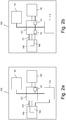
- the on-board device 100 preferably comprises a battery 110, a data processing unit 120, a non-volatile memory 130, a radiofrequency communication stage 140, a short-range communication stage 150 and a volatile memory 160.
- the on-board device 100 may comprise other components (for example GNSS components for satellite positioning) which will not be described in greater detail hereinbelow since they are not useful for the purposes of the present description.
- the battery 110 is preferably electrically connected directly or indirectly to each of the other components of the on-board device 110, so as to power them if and when necessary.
- the battery 110 is preferably electrically connected to the data processing unit 120 which is in turn electrically connected to the non-volatile memory 130, to the radiofrequency communication stage 140 and to the short-range communication stage 150.
- the electrical connection between the battery 110 and the non-volatile memory 130 may pass via the data processing unit 120.
- It may comprise a first switch S1 and, preferably, also a voltage regulator (not shown in Figures 2a-2d ).
- the switch S1 may be provided inside the data processing unit 120 (as schematically shown in Figures 2a-2d ) or outside thereof.
- the switch S1 is preferably also present in the case where the memory 130 is integrated in the data processing unit 120.
- the switch S1 is preferably controlled at a hardware level depending on the mode assumed by the data processing unit 120, as will be described in greater detail herein below.
- the battery 110 is directly connected electrically to the short-range communication stag 150 (namely there is no switch) such that the short-range communication stage 150 is constantly powered (until the battery 110 is charged).
- the electrical connection between battery 110 and short-range communication stage 150 may pass through the data processing unit 120, or instead bypass the data processing unit 120, as shown in Figures 2a and 2c .
- the electrical connection between the battery 110 and the short-range communication stage 150 comprises a switch S2.
- the switch S2 may also be provided inside the data processing unit 120 (as schematically shown in Figures 2b and 2d ) or outside thereof.
- the switch S2 is also preferably controlled at a hardware level depending on the mode assumed by the data processing unit 120, as will be described in greater detail herein below.
- the data processing unit 120 is electrically connected to the short-range communication stage 150 also by means of a further electrical connection 170 via which the data processing unit 120 receives wake-up electric signals, as will be described in greater detail below.
- the data processing unit 120 is instead electrically connected to a pushbutton 180 accessible from outside the on-board device 100 by means of a further electrical connection 170' via which the data processing unit 120 receives wake-up electric signals, as will be described in greater detail herein below.
- the on-board device 100 may comprise both the connection 170 and the pushbutton 180 and the connection 170', so that the data processing unit 120 may receive wake-up electric signals both from the short-range communication stage 150 and from the pushbutton 180, as will be described in greater detail herein below.
- the non-volatile memory 130 may be provided outside or inside the data processing unit 120. In any case, the non-volatile memory 130 is accessible by the data processing unit 120 alone. In particular it is not accessible by the short-range communication stage 150.
- the non-volatile memory 130 preferably stores a hardware identifier UID 120 of the data processing unit 120 (preferably, its silicon number) in a manner non-alterable and non-erasable (other than by using special software).
- This hardware identifier UID 120 is used by the data processing unit 120 to check the authenticity of the data read from the non-volatile memory 130. This advantageously makes it possible to prevent the contents of the central operating memory of an on-board device from being cloned and transferred onto another on-board device.
- non-volatile memory 130 is provided outside the data processing unit 120, an interface (not shown in the drawings) is provided between the unit 120 and the non-volatile memory 130, said interface being configured to perform encryption (preferably hardware encryption) of the data which the unit 120 reads from the memory 130.
- encryption preferably hardware encryption
- the data stored in the non-volatile memory 130 is thus advantageously protected, preferably at the hardware level.
- the non-volatile memory 130 therefore acts as a secure central operating memory of the on-board device 100.
- the non-volatile memory 130 stores the unique identification code OBU-ID of the on-board device 100 and, optionally, information about the user who is owner of the vehicle and about the vehicle itself (for example number plate and/or toll class of vehicle).
- the non-volatile memory 130 also preferably stores the software applications which provide the telematic traffic services for the user and/or the administrator supported by the on-board device 100 and the data generated by communication of the on-board device 100 with the road-side devices of the system via the radiofrequency communication stage 140 (for example, data relating to the position of the vehicle or its passage through motorway transit points).
- the radiofrequency communication stage 140 is preferably configured to establish radio links with the road-side devices.
- the radiofrequency stage 140 may be implemented using DSRC (Dedicated Short Range Communications) technology which, as is known, comprises radio channels and authentication, encoding and decoding procedures which have been specifically developed for telematic traffic services and uses frequency bands in the range of 5.7 - 5.9 GHz, for example in accordance with the provisions of the standards ETSI 200 674 and CEN TC 278.
- DSRC Dedicated Short Range Communications
- the short-range communication stage 150 is preferably configured to support short-range radio links (maximum 10 cm) with the electronic device 210.
- the electronic device 210 may belong to the same user who has been assigned the on-board device 100 or may belong to third parties (for example, the administrator of the road or motorway infrastructure along which the telematic traffic service supported by the on-board device 100 is provided, the telematic traffic service provider, or the body or authority responsible for monitoring traffic offences).
- the electronic device 210 is also preferably provided with cabled or wireless connectivity (for example WiFi or cellular network) to the communications network 600.
- the electronic device 210 may be a smartphone, a tablet or a generic commercial or specially designed reader.
- the electronic device 210 is also provided with a user interface 200 comprising input and/or output elements comprising for example pushbuttons, cursors, touchscreen features, etc.
- the electronic device 210 also comprises a short-range communication stage compatible with the short-range communication stage 150 of the on-board device 100.
- the short-range communication stage 150 (and therefore also the corresponding short-range communication stage of the electronic device 210) is realized using near-field technology, such as RFID (Radio-Frequency IDentification) technology with short range (i.e. radius less than 10 cm).
- RFID Radio-Frequency IDentification
- short range i.e. radius less than 10 cm.
- NFC Near Field Communication
- the short-range communication stage included in the electronic device 210 is configured as initiator, while the short-range communication stage 150 is configured as target.
- the short-range communication stage 150 is configured to receive from the short-range communication stage included in the electronic device 210 a radio carrier, from which it extracts its own power supply.
- the configuration of the short-range communication stage 150 as target is advantageous, since it allows the electronic and software complexity of the on-board unit to be reduced.
- the volatile memory 160 may be electrically connected to the short-range communication stage 150.
- the volatile memory 160 may be integrated in the short-range communication stage 150, as schematically shown in Figures 2a-2d .
- the volatile memory 160 is accessible by the short-range communication stage 150 which may carry out on it both write operations and read operations without involving the data processing unit 120, as will be described in greater detail herein below.
- the memory 160 is volatile (or temporary), namely it is unable to retain the data when it is not electrically powered.
- the memory 160 may be a RAM memory or buffer memory.
- the volatile memory 160 is preferably able to store in a temporary or transitory manner data exchanged between the electronic device 210 and the on-board device 100, as will be described in greater detail herein below.
- the communications protocol via which the short-range communication stage 150 and the corresponding short-range stage included in the electronic device 210 operate thus establishes automatically a radio link.
- the radio link thus established is preferably a two-way point-to-point link which allows a two-way exchange of data between on-board device 100 and electronic device 210.
- the establishment of the short-range radio link does not require any manual setting or any pairing procedure and is therefore very quick (about 1/10th of a second).
- the short-range link has a radius of 10 cm maximum, it is intrinsically secure against sniffing activities.
- the short-range communication stage 150 may transmit to the electronic device 210 data read by the components of the on-board device 100 (in particular, by the non-volatile central operating memory 130), thus allowing the reading of this data by the electronic device 210.
- These read operations may allow the user of the electronic device 210 (who may be the user who has been assigned the on-board device 100 or the personnel of the provider of the telematic traffic service supported by the on-board device 100) to carry out for example diagnostic checks or tests regarding operation of the on-board device 100 (for example, checking of the charged level of its battery 110) or checking of the data stored in the non-volatile memory 130.
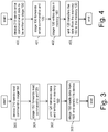
- the electronic device 210 preferably establishes a short-range connection with the short-range communication stage 150 and uses it to send a read command to the short-range communication stage 150 (step 300).
- the short-range communication stage 150 forwards the read command to the data processing unit 120 (step 301).
- the data processing unit 120 then preferably retrieves the data requested (for example from the non-volatile memory 130) and stores it temporarily in the volatile memory 160 (step 302).
- the volatile memory 160 preferably one or more protected areas, or one or more areas with write functionality enabled solely by the data processing unit 120, and not by the short-range communication stage 150, are provided in the volatile memory 160.
- step 302 also involves encryption of the recovered data, as will be described in greater detail below.
- the short-range communication stage 150 reads finally the data from the volatile memory 160 and forwards it to the electronic device 210 (step 303).
- the data read may be displayed in the form of texts or graphics on the user interface 200 of the electronic device 210.
- the data read may be transmitted from the electronic device 210 to the central server 700 via the communications network 600.
- the short-range communication stage 150 may receive from the electronic device 210 data to be supplied to the other components of the on-board device 100 (in particular to the data processing unit 120 and/or to the non-volatile memory 130), thus allowing writing of this data onto the on-board device 100 via the electronic device 210.
- These write operations may for example allow the user of the electronic device 210 (who may be the user who has been assigned the on-board device 100 or the personnel of the provider of the telematic traffic service supported by the on-board device 100) to modify the configuration of the on-board device 100, for example updating or activating the software applications which are already present or loading new applications or removing or deactivating those applications which are no longer of interest for the user.
- These write operations may therefore be advantageously performed without having to visit a customer service operating centre.
- the electronic device 210 preferably establishes a short-range connection with the short-range communication stage 150 and uses it to send a write command to the short-range communication stage 150 (step 400).
- the write command comprises (or is followed by) the data to be written, preferably in encrypted form.
- the electronic device 210 receives data to be written, in encrypted form from the central server 700 via the communications network 600.
- the electronic device 210 preferably does not perform any processing of the data to be written, merely performing a function a transducer between the connection to the communications network 600 (for example Wi-Fi or cellular network) and the short-range radio connection (for example NFC).
- the short-range communication stage 150 preferably forwards the write command to the data processing unit (step 401) and saves in the volatile memory 160 where it is temporarily stored (step 402).
- the steps 401 and 402 may be performed in the order shown, or in the reverse order (first the step 402 and then the step 401).
- a write protection mechanism in the form of a passcode is provided.
- the data processing unit 120 upon reception of the write command, reads the data temporarily stored by the volatile memory 160, processes it (in particular decrypts it, as will be described in greater detail hereinbelow) and transfer the data into the non-volatile memory 130 (step 403).
- the on-board device 100 may be provided with one or more indicators (for example LED light indicators) able to provide the user with visual feedback as regards the outcome of the data write operation on the on-board device 100.
- the on-board device 100 may be provided with a light indicator suitable for signalling to the user whether the operation of writing the data in the non-volatile memory 130 has been successfully completed.
- the behaviour of the on-board device 100 may have different variants.
- the short-range communication stage 150 upon reception of a read command or a write command from the electronic device 210, the short-range communication stage 150 preferably generates and sends automatically to the data processing unit 120 (which is in stand-by mode) an electric wake-up signal along the electrical connection 170. In response to this wake-up signal, the data processing unit 120 enters into an operative mode, closing the switch S1 and thus preparing to interact with the short-range communication stage 150 (including the volatile memory 160) and with the non-volatile memory 130.
- the data processing unit 120 may thus receive the read command from the short-range communication stage 150 (step 301) and read the data requested from the non-volatile memory 130 (step 302).
- the data processing unit 120 may initiate instead the processing and transfer of the data to be written from the volatile memory 160 to the non-volatile memory 130 (step 403).
- the data processing unit 120 preferably returns into stand-by mode, preferably opening again the switch S1, so as to avoid any current drainage in stand-by mode.
- the electric wake-up signal is sent via the electrical connection 170' to the data processing unit 120 from the pushbutton 180 which the user may press for example before the start of the read or write operation.
- This variant may be used, for example, in the case where the short-range communication stage 150 does not have the components necessary for the generation and sending of the electric wake-up signal or in the case where it is wished to avoid accidental or not authorized wake-ups which are of the data processing unit 120 (triggered for example by the involuntary or non-authorized movement close together of an electronic device 210, for example located outside the vehicle, and the on-board device 100 located inside the vehicle).
- the data processing unit 120 is in stand-by mode (switch S1 open) and, in response to the wake-up signal, enters into an operative mode, closing the switch S1.
- the data processing unit 120 Upon reception of a read command or a write command from the electronic device 210, the data processing unit 120 is therefore already ready to interact with the short-range communication stage 150 (including the volatile memory 160) and with the non-volatile memory 130, as described above. Likewise in this second variant, at the end of the write or read operation, the data processing unit 120 preferably returns into stand-by mode, opening again the switch S1.
- both the abovementioned mechanisms for wake-up of the data processing unit 120 may be used.
- the use of either one or the other may depend for example on the type of operation to be performed.
- wake-up by the short-range communication stage 150 may be performed for read operations
- wake-up by the pushbutton 180 may be performed for write operations.
- the data processing unit 120 is preferably configured to enable only read operations or only write operations, depending on whether the wake-signal comes from the short-range communication stage 150 or from the pushbutton 180.
- the volatile memory 160 is a RAM.
- the data may be kept stored in it so long as the battery 110 is charged. This data is therefore available for reading by the device 210, at least for as long as the battery 110 is charged.
- the short-range communication stage 150 (and therefore the volatile memory 160) is not constantly powered by the battery 110. Before sending the read or write command (and transferring the data) to the short-range communication stage 150, it is thus necessary to ensure that the processing unit 120 the switch S2.
- the electronic device 210 preferably sends a wake-up command to the short-range communication stage 150, before sending it a read or write command.
- the short-range communication stage 150 preferably generates and sends automatically to the data processing unit 120 an electric wake-up signal via the electrical connection 170.
- the data processing unit 120 is in stand-by mode, with the switches S1 and S2 open.
- the data processing unit 120 enters into operative mode, closing the switch S1 (so as to allow read and write access to the non-volatile memory 130) and also the switch S2. This latter operation also causes the short-range communication stage 150 and the volatile memory 160 to start being powered by the battery 110.
- the short-range communication stage 150 may thus receive and carry out a read command and/or a write command (and therefore transfer also the data) interacting with the data processing unit 120 as described above.
- the data processing unit 120 preferably returns into stand-by mode, opening again the switches S1 and S2.
- the wake-up signal is sent directly via the electrical connection 170' to the data processing unit 120 by the pushbutton 180 which the user presses before the start of the read or write operation.
- this variant may be used, for example, in the case where the short-range communication stage 150 does not have the components necessary for the generation and sending of the electric wake-up signal or in the case where the stage 150 is unable to generate the electric wake-up signal without being externally powered or in the case where it is wished to avoid accidental wake-up of the data processing unit 120 activated for example by the involuntary or non-authorized movement close together of electronic device 210 and on-board device 100.
- the data processing unit 120 in response to the wake-up signal, the data processing unit 120 enters into operative mode, closing the switch S1 (so as to allow read and write access to the non-volatile memory 130) and also the switch S2.
- the short-range communication stage 150 may thus receive and carry out a read command and/or a write command interacting with the data processing unit 120 (which is already operative) as described above.
- the data processing unit 120 At the end of the write or read operation, the data processing unit 120 preferably returns into stand-by mode, opening again the switches S1 and S2.
- the on-board device 100 may comprise both the electrical connection 170 and the pushbutton 180 and the electrical connection 170', such that both the wake-up mechanisms of the data processing unit 120 described above may be used (for example, as described above, wake-up by the short-range communication stage 150 for read operations and wake-up by the pushbutton 180 for write operations).
- the data processing unit 120 is permanently in operative mode.
- the read and/or write commands received by the short-range communication stage 150 may be directly carried out, without the need for any wake-up signal.
- the on-board device 100 therefore is substantially able to operate in two different operating configurations:
- a mechanism for protection of the data transmitted between electronic device 210 (or central server 700) and on-board device 100 is provided. It is preferably based on symmetric encryption of the transmitted data.
- This symmetric encryption uses a same private key to encrypt and decrypt the data, which key must therefore be known both to the central server 700 and to the on-board device 100.
- the private key is stored in the non-volatile memory 130 of the on-board device 100, preferably in an area which is non-erasable and non-modifiable (except by special software) of the non-volatile memory 130.
- the central server 700 preferably encrypts the data to be written with the private key and transmits it to the electronic device 210, which forwards it to the short-range communication stage 150 which, as described above, temporarily stores it the volatile memory 160.
- the data processing unit 120 (upon reception of the wake-up signal, as described above) decrypts the data to be written using the private key stored in the non-volatile memory 130 and transfers it into the non-volatile memory 130. This operation may be performed in different ways.
- the data processing unit 120 first transfers the encrypted data from the volatile memory 160 the non-volatile memory 130 and then decrypts it, using the symmetric key stored in the non-volatile memory 130.
- the data processing unit 120 first retrieves the symmetric key from the non-volatile memory 130, then uses it to decrypt the data (for example saved temporarily in an associated internal RAM memory), and finally transfers it into the non-volatile memory 130.
- the data to be decrypted and the private key which is used to decrypt it reside in two physically separate memories, one of which (namely the non-volatile memory 130 which stores the private key) is accessible only by the data processing unit 120 and therefore is not accessible by the short-range communication stage 150.
- the short-range communication stage 150 allows an unprotected connection to be established between electronic device 210 and on-board device 100, the on-board device 100 is advantageously very secure.
- the security of the private key used for symmetric encryption is preferably ensured in the manner described below.
- personalisation of the on-board device 100 is performed at the factory, this operation comprising the following steps:
- the central server 700 preferably uses a second secure HSM server (also containing the master key(s)), supplying it with the unique identification code OBU-ID of the on-board device 100 and obtaining from it the specific derived key to be used for communication with the on-board device 100.
- the transmitted data, encrypted by the central server 700 with derived key is received as described above by the data processing unit 120 which, using the appropriate derived key stored in the non-volatile memory 130, decrypts the data received which is finally stored in the non-volatile memory 130.
- a session key may also be used for communication between the central server 700 and the on-board device 100.
- the sender namely the central server 700 if data is written in the on-board device 100, or the on-board device 100 if data is read from the on-board device 100 calculates a session key, for example on the basis of the derived key and a random number.
- the session key is recalculated (and is therefore different) for each communication session.
- the sender preferably uses the calculated session key to encrypt further the data to be transmitted, already encrypted with the derived key of the symmetric encryption mechanism.
- the sender also preferably encrypts the calculated session key, using for example the public key of the recipient (namely the on-board device 100 if data is written, or the central server 700 if data is read) and also sends this to the recipient.
- the recipient upon reception of the data and the encrypted session key, decrypts the session key using the associated private key and then uses the session key to decrypt the data received (to be further decrypted using the derived key).
- This mechanism is advantageous, since it represents a solution which is less complex from a computational point of view compared to asymmetric encryption of all the data exchanged between central server 700 and on-board device 100 and which allows the calculation time necessary for encryption and decryption of the exchanged data to be reduced significantly.
- protection with the session key is used only on the connection between electronic device 210 and central server 700.
- the management of the session keys in this case is entrusted to the electronic device 210 and not to the on-board device 100.
- Figure 5 shows an on-board device according to a second embodiment of the present invention.
- the on-board device 100' preferably comprises all the components of the on-board device 100 shown in Figure 2d (but may correspond to any one of the other variants shown in Figures 2a-2c ) and, in addition, also another non-volatile memory 160', called below also “non-volatile tag memory” or “tag memory”.
- the non-volatile tag memory 160' may be connected to the short-range communication stage 150, as shown schematically in Figure 5 .
- the non-volatile tag memory 160' may be incorporated in the short-range communication stage 150. In both cases, the non-volatile tag memory 160' is accessible to the short-range communication stage 150, while it is not accessible to the data processing unit 120.
- the tag memory 160' is a non-volatile memory able to retain the data even when not electrically powered.
- the non-volatile tag memory 160' may be a memory of the E 2 PROM type.
- the tag memory 160' preferably permanently stores a set of basic data relating to the on-board device 100' and comprising the unique identification code OBU-ID of the on-board device 100' and, optionally, information about the user and/or the vehicle.
- the short-range communication stage 150 may allow reading, via the electronic device 210, of the data stored in the tag memory 160', for example the aforementioned basic data of the device 100'.
- the short-range communication stage 150 advantageously retrieves the requested data from the tag memory 160' and sends it directly to the electronic device 210. This operation does not require any action either by the data processing unit 120 or by the battery 110.
- the basic data stored in the tag memory 160' can therefore be advantageously read by means of the electronic device 210, irrespective as to whether the on-board device 100 is functioning or not.
- the tag memory 160' therefore advantageously performs substantially an electronic tag function.
- the short-range communication stage 150 may allow modification or rewriting of the data to be kept available in the tag memory 160', for example the aforementioned basic data of the device 100'.
- the short-range communication stage 150 advantageously stores directly this data (optionally overwriting the old data) in the tag memory 160'. In this case too, the operation does not require any action either by the data processing unit 120 or by the battery 110.
- the short-range communication stage 150 allows not only the reading/writing of data in the non-volatile memory 130 via the volatile memory 160, but also reading/writing of data in the non-volatile memory 160' in electronic tag mode.
- Figure 6 shows an on-board device according to a third embodiment of the present invention.
- the on-board device 100" preferably comprises all the components of the on-board device 100' shown in Figure 5 and, in addition, also a further short-range communication stage 150'.
- the short-range communication stage 150' is similar to the short-range communication stage 150. Therefore, a detailed description thereof will not be repeated.
- the non-volatile tag memory 160' may be connected to the short-range communication stage 150.
- the non-volatile tag memory 160' may be incorporated in the short-range communication stage 150', as schematically shown in Figure 6 .
- the non-volatile tag memory 160' is accessible only to the short-range communication stage 150', while it is not accessible to any other component of the on-board device 100".
- the short-range communication stage 150' is neither logically nor electrically connected to any other component of the on-board device 100", except for the non-volatile tag memory 160'.
- the short-range communication stage 150 allows the reading/writing of data in the non-volatile memory 130 via the volatile memory 160, while the short-range communication stage 150' allows the reading/writing of data in the non-volatile memory 160' in electronic tag mode.
- the tag memory 160' is preferably protected during access (i.e. both during reading and during writing) at least by means of an access mechanism based on a passcode.
- a mechanism is also provided for ensuring the authenticity of the data read from the tag memory 160', i.e. guaranteeing for the electronic device 210 and/or the central server 700 that the read data really relates to the on-board device 100 and instead has not been cloned by another on-board device.
- this mechanism is based on asymmetric encryption of the data made available during reading by means of permanent storage in the tag memory 160'.
- the data readable from the tag memory 160' is stored in the tag memory 160' encrypted with a private key.
- the central server 700 sends to the on-board device the data to be rendered readable from the tag memory 160' in a form already encrypted with private key.
- the short-range communication stage 150 may store it directly in the tag memory 160', without requesting any action on the part of the data processing unit 120.
- This second mechanism is the only one applicable according to the third embodiment, where the short-range communication stage 150' is not logically connected to the data processing unit 120.
- the data to be made readable from the tag memory 160' may be transmitted by the central server 700 unencrypted with a password which enables writing in the tag memory 160' and prevents overwriting or modification of this data by persons not in possession of the password.
- the electronic device 210 uses the public key in order to decrypt the read data which is encrypted with private key.
- the public key since it may be freely distributed, is preferably saved locally in the electronic device 210 (for example within an application executed by the device 210 for managing the reading of data from the device 100), such that the electronic device 210 is not dependent on the connection with the central server 700 during the whole of the operation of reading of the data stored in the tag memory 160'.
- the hardware identifier UID 160 is preferably written by the manufacturer of the tag memory 160' in a specific area thereof, so that it is stored permanently and is available in read-only mode and therefore cannot be modified.
- the hardware identifier UID 160 is stored both unencrypted and encrypted with private key together with the data to be rendered readable (for example the basic data) permanently saved in the tag memory 160' (containing, as described above, the identifier OBU-ID and optionally data about the user and/or the vehicle).
- the hardware identifier UID 160 is preferably transmitted to the electronic device 210 unencrypted, together with the data to be read encrypted with private key.
- the electronic device 210 After carrying out decryption of the data to be read with public key, the electronic device 210 preferably compares the hardware identifier UID 160 received unencrypted with the hardware identifier UID 160 obtained from decryption with public key. If the two hardware identifiers coincide, the data to be read is further authenticated.
- the private key (which is the same for encryption and decryption) is preferably known only to the central server 700 and the on-board device 100. Therefore, reading of this data in electronic tag mode by the electronic device 210 requires in any case forwarding of the data to the central server 700 which decrypts it with the private key known to it and, if authenticated, retransmits it unencrypted to the electronic device 210.
- the on-board device 100, 100', 100" is equipped with a data connection interface (for example if it is a satellite device also equipped with radio communication technology or Bluetooth), writing and reading of the data in the memory 130 may be managed by the data processing unit 120, interfaced in this case with the data connection interface (for example the radio communication technology internal modem or Bluetooth interface).
- the data connection interface for example the radio communication technology internal modem or Bluetooth interface.
- the short-range communication stage 150 may be used solely for the function of reading data from the tag memory 160'.
- the on-board device described in addition to allowing the reading of data (for example for verification or diagnostic purposes) and the writing of data (for example for configurational purposes) by the electronic device 210 allows in fact the exchange of data with the electronic device 210 and with the central server 700 to be managed in a particularly secure manner.
Landscapes
- Engineering & Computer Science (AREA)
- Business, Economics & Management (AREA)
- Theoretical Computer Science (AREA)
- General Physics & Mathematics (AREA)
- Physics & Mathematics (AREA)
- Accounting & Taxation (AREA)
- Computer Networks & Wireless Communication (AREA)
- Computer Security & Cryptography (AREA)
- General Business, Economics & Management (AREA)
- Strategic Management (AREA)
- Finance (AREA)
- Computer Hardware Design (AREA)
- Software Systems (AREA)
- General Engineering & Computer Science (AREA)
- Development Economics (AREA)
- Economics (AREA)
- Health & Medical Sciences (AREA)
- Computing Systems (AREA)
- General Health & Medical Sciences (AREA)
- Medical Informatics (AREA)
- Signal Processing (AREA)
- Transceivers (AREA)
- Mobile Radio Communication Systems (AREA)
Claims (15)
- Bordgerät (100, 100', 100") für ein Fahrzeug, wobei das Bordgerät (100, 100', 100") geeignet ist zur Verwendung in einem System, welches einen telematischen Verkehrsdienst bereitstellt, wobei das Bordgerät (100, 100', 100") aufweist:
eine Funkfrequenz-Kommunikationsstufe (140), welche konfiguriert ist, um mit einer straßenseitigen Einrichtung des Systems zu kommunizieren;- eine Nahbereichs-Kommunikationsstufe (150), welche konfiguriert ist, mit einer elektronischen Einrichtung (210) zu kommunizieren, die sich in der Nähe hiervon befindet;- eine Datenverarbeitungseinheit (120), die mit der Funkfrequenz-Kommunikationsstufe (140) und der Nahbereichs-Kommunikationsstufe (150) zusam menarbeitet,- einen nicht flüchtigen zentraler Betriebsspeicher (130), welcher für die Datenverarbeitungseinheit (120) zugänglich und für die Nahbereichs-Kommunikationsstufe (150) nicht zugänglich ist; und- einen flüchtigen Speicher (160), welcher für die Nahbereichs-Kommunikationsstufe (150) und für die Datenverarbeitungseinheit (120) zugänglich ist,- wobei der flüchtige Speicher (160) geeignet ist, zum zeitweisen Speichern von Daten, die gelesen werden sollen von und/oder Daten, die geschrieben werden sollen in dem/den nicht flüchtigen zentralen Betriebsspeicher (130) durch die externe Einrichtung (210) über die Nahbereichs-Kommunikationsstufe (150) und die Datenverarbeitungseinheit (120). - Bordgerät (100, 100', 100") nach Anspruch 1, des Weiteren aufweisend:
eine Batterie (110), die direkt oder indirekt mit der Funkfrequenz-Kommunikationsstufe (140) der Nahbereichs-Kommunikationsstufe (150), der Datenverarbeitungseinheit (120), dem nicht flüchtigen zentralen Betriebsspeicher (130) und dem flüchtigen Speicher (160) elektrisch verbunden ist. - Bordgerät (100, 100', 100") nach Anspruch 2, wobei die Batterie (110) mit dem nicht flüchtigen zentralen Betriebsspeicher (130) über Mittel eines ersten Schalters (S1) elektrisch verbunden ist, wobei der erste Schalter (S1) offen ist, wenn die Datenverarbeitungseinheit (120) im Stand-by-Modus ist und der erste Schalter (S1) geschlossen ist, wenn die Datenverarbeitungseinheit (120) im Betriebsmodus ist.
- Bordgerät (100, 100', 100") nach Anspruch 3,
wobei der erste Schalter (S1) innerhalb der Datenverarbeitungseinheit (120) vorgesehen ist und konfiguriert ist, sich automatisch zu schließen, wenn die Datenverarbeitungseinheit (120) vom Stand-by-Modus in den Betriebsmodus wechselt. - Bordgerät (100, 100', 100") nach Anspruch 3 oder 4,
wobei die Batterie (110) direkt mit der Nachbereichskommunikationsstufe (150) elektrisch verbunden ist. - Bordgerät (100, 100', 100") nach Anspruch 5,
wobei der flüchtige Speicher (160) ein RAM-Speicher oder ein Kofferspeicher ist. - Bordgerät (100, 100', 100") nach Anspruch 3 oder 4,
wobei die Batterie (110) mit der Nachbereichskommunikationsstufe (150) über Mittel eines zweiten Schalters (S2) elektrisch verbunden ist, wobei der zweite Schalter (S2) offen ist, wenn die Datenverarbeitungseinheit (120) im Stand-by-Modus ist und der zweite Schalter (S2) geschlossen ist, wenn die Datenverarbeitungseinheit (120) im Betriebsmodus ist. - Bordgerät (100, 100', 100") nach Anspruch 7,
wobei der zweite Schalter (S2) innerhalb der Datenverarbeitungseinheit (120) vorgesehen ist. - Bordgerät (100, 100', 100") nach einem der Ansprüche 3 bis 8,
wobei die Datenverarbeitungseinheit (120) mit der Nahbereichs-Kommunikationsstufe (150) auch durch Mittel einer elektrischen Verbindung (170) elektrisch verbunden ist und wobei:- die Nachbereichs-Kommunikationsstufe (150) konfiguriert ist, um ein Aufwachsignal zu erzeugen und an die Datenverarbeitungseinheit (120) über die elektrische Verbindung (170) zu senden; und- die Datenverarbeitungseinheit (120) konfiguriert ist, um beim Empfang des Aufwachsignals vom Stand-by-Modus in einen Betriebsmodus überzugehen, wobei der Schalter (S1) geschlossen wird. - Bordgerät (100, 100', 100") nach einem der Ansprüche 3 bis 9, ferner aufweisend: einen Druckknopf (180), der an der Außenseite des Bordgerätes (100) zugänglich ist und elektrisch mit der Datenverarbeitungseinheit (120) durch Mittel einer weiteren elektrischen Verbindung (170') verbunden ist und wobei:- der Druckknopf (180) konfiguriert ist, um, wenn er gedrückt wird, ein weiteres Aufwachsignal zu erzeugen und an die Datenverarbeitungseinheit (120) über die weitere elektrische Verbindung (170) zu senden; und- die Datenverarbeitungseinheit (120) konfiguriert ist, um beim Empfang des weiteren Aufwachsignals von einem Stand-by-Modus in einen Betriebsmodus überzugehen, wobei der Schalter (S1) geschlossen wird.
- Bordgerät (100, 100', 100") nach Anspruch 9 und 10,
wobei die Verarbeitungseinheit (120) konfiguriert ist:- beim Empfang des Aufwachsignals von der Nahbereichs-Kommunikationsstufe (150) nur Operationen zum Lesen von Daten aus dem nicht flüchtigen Betriebsspeicher (130) zu ermöglichen; und- beim Empfang des weiteren Aufwachsignals von dem Druckknopf (180) nur Operationen zum Schreiben von Daten in den nicht flüchtigen zentralen Betriebsspeicher (130) zu ermöglichen. - Bordgerät (100, 100', 100") nach einem der vorangehenden Ansprüche,
wobei der flüchtige Speicher (160) aufweist:- mindestens einen ersten Speicherbereich in welchen die Nahbereichs-Kommunikationsstufe (150) nur die in den nicht flüchtigen zentralen Betriebsspeicher (130) zu schreibenden Daten schreiben kann und von welchen die Datenverarbeitungseinheit (120) nur die in den nicht flüchtigen zentralen Betriebsspeicher (130) zu schreibenden Daten lesen kann; und/oder- mindestens einen zweiten Speicherbereich in welchen Datenverarbeitungseinheit (120) nur die Daten, die von dem nicht flüchtigen zentralen Betriebsspeicher (130) gelesen werden sollen, schreiben kann und von dem die Nahbereichs-Kommunikationsstufe (150) nur die Daten lesen kann, welche von dem nicht flüchtigen zentralen Betriebsspeicher (130) gelesen werden sollen. - Bordgerät (100') nach einem der vorangehenden Ansprüche des Weiteren aufweisend:
einen weiteren nicht flüchtigen Speicher (160'), der konfiguriert ist, einen Satz von zweiten Daten, die sich auf das Bordgerät (100') beziehen zu speichern, wobei auf den weiteren nicht flüchtigen Speicher (160') durch die Nahbereichs-Kommunikationsstufe (150) zugegriffen werden kann, wobei die Nachbereichs-Kommunikationsstufe (150) konfiguriert ist, um die zweiten Daten von dem weiteren nicht flüchtigen Speicher (160') zu lesen und sie zu der elektronischen Einrichtung (210) zu senden. - Bordgerät (100") nach einem der Ansprüche 1 bis 12, ferner aufweisend:
eine weitere Nahbereichs-Kommunikationsstufe (150') und einen weiteren nicht flüchtigen Speicher (160'), der geeignet ist, einen Satz von zweiten Daten, welche sich auf das Bordgerät (100') beziehen, zu speichern, wobei auf den weiteren nicht flüchtigen Speicher (160') durch die Nahbereichs-Kommunikationsstufe (150') zugegriffen werden kann, wobei die Nahbereichs-Kommunikationsstufe (150') ferner konfiguriert ist, um die zweiten Daten aus dem weiteren nicht flüchtigen Speicher (160') auszulesen und sie an die elektronische Einrichtung (210) zu senden. - System zum Bereitstellen von telematischen Verkehrsdaten, wobei das System eine Vielzahl von straßenseitigen Einrichtungen, eine elektronische Einrichtung (210) und ein Bordgerät (100) für ein Fahrzeug aufweist, wobei das Bordgerät (100) konfiguriert ist, mit beiden, der Vielzahl von straßenseitigen Einrichtungen und mit der elektronischen Einrichtung (210) zu kommunizieren, wobei das Bordgerät (100) nach einem der Ansprüche 1 bis 14 ist.
Priority Applications (6)
| Application Number | Priority Date | Filing Date | Title |
|---|---|---|---|
| ES17176161T ES2810226T3 (es) | 2017-06-15 | 2017-06-15 | Dispositivo de a bordo para un vehículo |
| DK17176161.2T DK3416352T3 (da) | 2017-06-15 | 2017-06-15 | Indbygget indretning til fartøj |
| EP17176161.2A EP3416352B1 (de) | 2017-06-15 | 2017-06-15 | Bordvorrichtung für ein fahrzeug |
| PL17176161T PL3416352T3 (pl) | 2017-06-15 | 2017-06-15 | Urządzenie pokładowe do pojazdu |
| PCT/EP2018/065435 WO2018229023A1 (en) | 2017-06-15 | 2018-06-12 | On-board device for a vehicle |
| CL2019003588A CL2019003588A1 (es) | 2017-06-15 | 2019-12-06 | Dispositivo de a bordo para un vehículo. |
Applications Claiming Priority (1)
| Application Number | Priority Date | Filing Date | Title |
|---|---|---|---|
| EP17176161.2A EP3416352B1 (de) | 2017-06-15 | 2017-06-15 | Bordvorrichtung für ein fahrzeug |
Publications (2)
| Publication Number | Publication Date |
|---|---|
| EP3416352A1 EP3416352A1 (de) | 2018-12-19 |
| EP3416352B1 true EP3416352B1 (de) | 2020-05-20 |
Family
ID=59399217
Family Applications (1)
| Application Number | Title | Priority Date | Filing Date |
|---|---|---|---|
| EP17176161.2A Active EP3416352B1 (de) | 2017-06-15 | 2017-06-15 | Bordvorrichtung für ein fahrzeug |
Country Status (6)
| Country | Link |
|---|---|
| EP (1) | EP3416352B1 (de) |
| CL (1) | CL2019003588A1 (de) |
| DK (1) | DK3416352T3 (de) |
| ES (1) | ES2810226T3 (de) |
| PL (1) | PL3416352T3 (de) |
| WO (1) | WO2018229023A1 (de) |
Families Citing this family (2)
| Publication number | Priority date | Publication date | Assignee | Title |
|---|---|---|---|---|
| IT202100016715A1 (it) * | 2021-06-25 | 2022-12-25 | Telepass S P A | Unita’ di bordo veicolare per servizi di traffico stradale con trasponder di comunicazione a radiofrequenza |
| CN113960394B (zh) * | 2021-10-15 | 2024-05-14 | 北京聚利科技有限公司 | 车载单元的检测方法、装置、检测设备和可读存储介质 |
Family Cites Families (2)
| Publication number | Priority date | Publication date | Assignee | Title |
|---|---|---|---|---|
| JP2004348579A (ja) * | 2003-05-23 | 2004-12-09 | Mitsubishi Electric Corp | データ不正使用防止装置 |
| ES2555468T3 (es) | 2013-04-19 | 2016-01-04 | Kapsch Trafficcom Ag | Instalación de a bordo para un vehículo |
-
2017
- 2017-06-15 EP EP17176161.2A patent/EP3416352B1/de active Active
- 2017-06-15 DK DK17176161.2T patent/DK3416352T3/da active
- 2017-06-15 ES ES17176161T patent/ES2810226T3/es active Active
- 2017-06-15 PL PL17176161T patent/PL3416352T3/pl unknown
-
2018
- 2018-06-12 WO PCT/EP2018/065435 patent/WO2018229023A1/en active Application Filing
-
2019
- 2019-12-06 CL CL2019003588A patent/CL2019003588A1/es unknown
Non-Patent Citations (1)
| Title |
|---|
| None * |
Also Published As
| Publication number | Publication date |
|---|---|
| ES2810226T3 (es) | 2021-03-08 |
| PL3416352T3 (pl) | 2020-11-16 |
| EP3416352A1 (de) | 2018-12-19 |
| CL2019003588A1 (es) | 2020-06-19 |
| WO2018229023A1 (en) | 2018-12-20 |
| DK3416352T3 (da) | 2020-08-10 |
Similar Documents
| Publication | Publication Date | Title |
|---|---|---|
| US10569739B2 (en) | Virtual keyfob for vehicle sharing | |
| US8635462B2 (en) | Method and device for managing access control | |
| CA2632298C (en) | Integrated access control system and a method of controlling the same | |
| US11663867B2 (en) | Digital certificate and reservation | |
| AU2005304254B2 (en) | Method and system for the user-specific initialization of identification devices in the field | |
| US20070257774A1 (en) | Method and Device for Delivery or Obtaining of a Good | |
| CN104952128A (zh) | 一种基于智能手持终端的电子解锁系统及其解锁方法 | |
| IL258598A (en) | System and method for method control | |
| JP3445490B2 (ja) | 移動体通信方法および移動体通信システム | |
| EP3238182B1 (de) | Bordvorrichtung für ein fahrzeug | |
| EP3416352B1 (de) | Bordvorrichtung für ein fahrzeug | |
| KR20180109039A (ko) | 스터디카페의 출입문 제어 시스템 및 방법 | |
| KR102146748B1 (ko) | 모바일 보안 환경에서의 디지털 키 서비스 시스템 및 그 방법 | |
| EP2716510B1 (de) | Authentifizierungssystem und Verfahren für einen Fahrzeugpark | |
| JP2014215705A (ja) | 車載器制御システム | |
| JP6088825B2 (ja) | 料金決済処理システムおよび料金決済処理方法 | |
| KR102142906B1 (ko) | 모바일 보안환경에서의 디지털 키 서비스 시스템 | |
| ES2712643T3 (es) | Método para la transmisión a través de una red de telecomunicaciones de una información de autorización o de una autorización asociada con un terminal de telecomunicación, terminal de telecomunicación, sistema, programa informático y de programa informático | |
| EP1926263A2 (de) | Zugangskontrollsystem zur Kontrolle des Zugangs eines Benutzers mobiler Geräte zu einem geschlossenen Bereich | |
| JP2010198488A (ja) | 決済システム | |
| KR20190084391A (ko) | 가상키를 이용한 차량 제어방법 | |
| EP4109416A1 (de) | Fahrzeugeinheit für den strassenverkehr mit einem transponder für funkkommunikation | |
| KR20180122538A (ko) | 무인으로 운영되는 아파트 지하주차장에서 자동차의 손상, 분실 등을 억제하는 비상벨 장치 | |
| JP6580868B2 (ja) | 情報提供システム、情報提供方法及びコンピュータプログラム | |
| CN114973435A (zh) | 一种检票的方法、闸机、服务器、移动终端及存储介质 |
Legal Events
| Date | Code | Title | Description |
|---|---|---|---|
| PUAI | Public reference made under article 153(3) epc to a published international application that has entered the european phase |
Free format text: ORIGINAL CODE: 0009012 |
|
| STAA | Information on the status of an ep patent application or granted ep patent |
Free format text: STATUS: THE APPLICATION HAS BEEN PUBLISHED |
|
| AK | Designated contracting states |
Kind code of ref document: A1 Designated state(s): AL AT BE BG CH CY CZ DE DK EE ES FI FR GB GR HR HU IE IS IT LI LT LU LV MC MK MT NL NO PL PT RO RS SE SI SK SM TR |
|
| AX | Request for extension of the european patent |
Extension state: BA ME |
|
| STAA | Information on the status of an ep patent application or granted ep patent |
Free format text: STATUS: REQUEST FOR EXAMINATION WAS MADE |
|
| 17P | Request for examination filed |
Effective date: 20190617 |
|
| RBV | Designated contracting states (corrected) |
Designated state(s): AL AT BE BG CH CY CZ DE DK EE ES FI FR GB GR HR HU IE IS IT LI LT LU LV MC MK MT NL NO PL PT RO RS SE SI SK SM TR |
|
| GRAP | Despatch of communication of intention to grant a patent |
Free format text: ORIGINAL CODE: EPIDOSNIGR1 |
|
| STAA | Information on the status of an ep patent application or granted ep patent |
Free format text: STATUS: GRANT OF PATENT IS INTENDED |
|
| INTG | Intention to grant announced |
Effective date: 20191210 |
|
| REG | Reference to a national code |
Ref country code: HK Ref legal event code: DE Ref document number: 40001752 Country of ref document: HK |
|
| GRAS | Grant fee paid |
Free format text: ORIGINAL CODE: EPIDOSNIGR3 |
|
| GRAA | (expected) grant |
Free format text: ORIGINAL CODE: 0009210 |
|
| STAA | Information on the status of an ep patent application or granted ep patent |
Free format text: STATUS: THE PATENT HAS BEEN GRANTED |
|
| AK | Designated contracting states |
Kind code of ref document: B1 Designated state(s): AL AT BE BG CH CY CZ DE DK EE ES FI FR GB GR HR HU IE IS IT LI LT LU LV MC MK MT NL NO PL PT RO RS SE SI SK SM TR |
|
| REG | Reference to a national code |
Ref country code: GB Ref legal event code: FG4D |
|
| REG | Reference to a national code |
Ref country code: CH Ref legal event code: EP |
|
| REG | Reference to a national code |
Ref country code: DE Ref legal event code: R096 Ref document number: 602017016945 Country of ref document: DE |
|
| REG | Reference to a national code |
Ref country code: AT Ref legal event code: REF Ref document number: 1273391 Country of ref document: AT Kind code of ref document: T Effective date: 20200615 |
|
| REG | Reference to a national code |
Ref country code: DK Ref legal event code: T3 Effective date: 20200806 |
|
| REG | Reference to a national code |
Ref country code: LT Ref legal event code: MG4D |
|
| REG | Reference to a national code |
Ref country code: NL Ref legal event code: MP Effective date: 20200520 |
|
| PG25 | Lapsed in a contracting state [announced via postgrant information from national office to epo] |
Ref country code: LT Free format text: LAPSE BECAUSE OF FAILURE TO SUBMIT A TRANSLATION OF THE DESCRIPTION OR TO PAY THE FEE WITHIN THE PRESCRIBED TIME-LIMIT Effective date: 20200520 Ref country code: FI Free format text: LAPSE BECAUSE OF FAILURE TO SUBMIT A TRANSLATION OF THE DESCRIPTION OR TO PAY THE FEE WITHIN THE PRESCRIBED TIME-LIMIT Effective date: 20200520 Ref country code: PT Free format text: LAPSE BECAUSE OF FAILURE TO SUBMIT A TRANSLATION OF THE DESCRIPTION OR TO PAY THE FEE WITHIN THE PRESCRIBED TIME-LIMIT Effective date: 20200921 Ref country code: IS Free format text: LAPSE BECAUSE OF FAILURE TO SUBMIT A TRANSLATION OF THE DESCRIPTION OR TO PAY THE FEE WITHIN THE PRESCRIBED TIME-LIMIT Effective date: 20200920 Ref country code: SE Free format text: LAPSE BECAUSE OF FAILURE TO SUBMIT A TRANSLATION OF THE DESCRIPTION OR TO PAY THE FEE WITHIN THE PRESCRIBED TIME-LIMIT Effective date: 20200520 Ref country code: NO Free format text: LAPSE BECAUSE OF FAILURE TO SUBMIT A TRANSLATION OF THE DESCRIPTION OR TO PAY THE FEE WITHIN THE PRESCRIBED TIME-LIMIT Effective date: 20200820 Ref country code: GR Free format text: LAPSE BECAUSE OF FAILURE TO SUBMIT A TRANSLATION OF THE DESCRIPTION OR TO PAY THE FEE WITHIN THE PRESCRIBED TIME-LIMIT Effective date: 20200821 |
|
| PG25 | Lapsed in a contracting state [announced via postgrant information from national office to epo] |
Ref country code: RS Free format text: LAPSE BECAUSE OF FAILURE TO SUBMIT A TRANSLATION OF THE DESCRIPTION OR TO PAY THE FEE WITHIN THE PRESCRIBED TIME-LIMIT Effective date: 20200520 Ref country code: BG Free format text: LAPSE BECAUSE OF FAILURE TO SUBMIT A TRANSLATION OF THE DESCRIPTION OR TO PAY THE FEE WITHIN THE PRESCRIBED TIME-LIMIT Effective date: 20200820 Ref country code: LV Free format text: LAPSE BECAUSE OF FAILURE TO SUBMIT A TRANSLATION OF THE DESCRIPTION OR TO PAY THE FEE WITHIN THE PRESCRIBED TIME-LIMIT Effective date: 20200520 Ref country code: HR Free format text: LAPSE BECAUSE OF FAILURE TO SUBMIT A TRANSLATION OF THE DESCRIPTION OR TO PAY THE FEE WITHIN THE PRESCRIBED TIME-LIMIT Effective date: 20200520 |
|
| PG25 | Lapsed in a contracting state [announced via postgrant information from national office to epo] |
Ref country code: AL Free format text: LAPSE BECAUSE OF FAILURE TO SUBMIT A TRANSLATION OF THE DESCRIPTION OR TO PAY THE FEE WITHIN THE PRESCRIBED TIME-LIMIT Effective date: 20200520 Ref country code: NL Free format text: LAPSE BECAUSE OF FAILURE TO SUBMIT A TRANSLATION OF THE DESCRIPTION OR TO PAY THE FEE WITHIN THE PRESCRIBED TIME-LIMIT Effective date: 20200520 |
|
| REG | Reference to a national code |
Ref country code: DE Ref legal event code: R119 Ref document number: 602017016945 Country of ref document: DE |
|
| PG25 | Lapsed in a contracting state [announced via postgrant information from national office to epo] |
Ref country code: CZ Free format text: LAPSE BECAUSE OF FAILURE TO SUBMIT A TRANSLATION OF THE DESCRIPTION OR TO PAY THE FEE WITHIN THE PRESCRIBED TIME-LIMIT Effective date: 20200520 Ref country code: RO Free format text: LAPSE BECAUSE OF FAILURE TO SUBMIT A TRANSLATION OF THE DESCRIPTION OR TO PAY THE FEE WITHIN THE PRESCRIBED TIME-LIMIT Effective date: 20200520 Ref country code: EE Free format text: LAPSE BECAUSE OF FAILURE TO SUBMIT A TRANSLATION OF THE DESCRIPTION OR TO PAY THE FEE WITHIN THE PRESCRIBED TIME-LIMIT Effective date: 20200520 Ref country code: SM Free format text: LAPSE BECAUSE OF FAILURE TO SUBMIT A TRANSLATION OF THE DESCRIPTION OR TO PAY THE FEE WITHIN THE PRESCRIBED TIME-LIMIT Effective date: 20200520 |
|
| REG | Reference to a national code |
Ref country code: CH Ref legal event code: PL |
|
| REG | Reference to a national code |
Ref country code: AT Ref legal event code: UEP Ref document number: 1273391 Country of ref document: AT Kind code of ref document: T Effective date: 20200520 |
|
| PG25 | Lapsed in a contracting state [announced via postgrant information from national office to epo] |
Ref country code: MC Free format text: LAPSE BECAUSE OF FAILURE TO SUBMIT A TRANSLATION OF THE DESCRIPTION OR TO PAY THE FEE WITHIN THE PRESCRIBED TIME-LIMIT Effective date: 20200520 Ref country code: SK Free format text: LAPSE BECAUSE OF FAILURE TO SUBMIT A TRANSLATION OF THE DESCRIPTION OR TO PAY THE FEE WITHIN THE PRESCRIBED TIME-LIMIT Effective date: 20200520 |
|
| REG | Reference to a national code |
Ref country code: ES Ref legal event code: FG2A Ref document number: 2810226 Country of ref document: ES Kind code of ref document: T3 Effective date: 20210308 |
|
| PLBE | No opposition filed within time limit |
Free format text: ORIGINAL CODE: 0009261 |
|
| STAA | Information on the status of an ep patent application or granted ep patent |
Free format text: STATUS: NO OPPOSITION FILED WITHIN TIME LIMIT |
|
| PG25 | Lapsed in a contracting state [announced via postgrant information from national office to epo] |
Ref country code: LU Free format text: LAPSE BECAUSE OF NON-PAYMENT OF DUE FEES Effective date: 20200615 |
|
| REG | Reference to a national code |
Ref country code: BE Ref legal event code: MM Effective date: 20200630 |
|
| 26N | No opposition filed |
Effective date: 20210223 |
|
| PG25 | Lapsed in a contracting state [announced via postgrant information from national office to epo] |
Ref country code: IE Free format text: LAPSE BECAUSE OF NON-PAYMENT OF DUE FEES Effective date: 20200615 Ref country code: LI Free format text: LAPSE BECAUSE OF NON-PAYMENT OF DUE FEES Effective date: 20200630 Ref country code: CH Free format text: LAPSE BECAUSE OF NON-PAYMENT OF DUE FEES Effective date: 20200630 |
|
| PG25 | Lapsed in a contracting state [announced via postgrant information from national office to epo] |
Ref country code: SI Free format text: LAPSE BECAUSE OF FAILURE TO SUBMIT A TRANSLATION OF THE DESCRIPTION OR TO PAY THE FEE WITHIN THE PRESCRIBED TIME-LIMIT Effective date: 20200520 Ref country code: DE Free format text: LAPSE BECAUSE OF NON-PAYMENT OF DUE FEES Effective date: 20210101 Ref country code: BE Free format text: LAPSE BECAUSE OF NON-PAYMENT OF DUE FEES Effective date: 20200630 |
|
| GBPC | Gb: european patent ceased through non-payment of renewal fee |
Effective date: 20210615 |
|
| PG25 | Lapsed in a contracting state [announced via postgrant information from national office to epo] |
Ref country code: GB Free format text: LAPSE BECAUSE OF NON-PAYMENT OF DUE FEES Effective date: 20210615 |
|
| PG25 | Lapsed in a contracting state [announced via postgrant information from national office to epo] |
Ref country code: TR Free format text: LAPSE BECAUSE OF FAILURE TO SUBMIT A TRANSLATION OF THE DESCRIPTION OR TO PAY THE FEE WITHIN THE PRESCRIBED TIME-LIMIT Effective date: 20200520 Ref country code: MT Free format text: LAPSE BECAUSE OF FAILURE TO SUBMIT A TRANSLATION OF THE DESCRIPTION OR TO PAY THE FEE WITHIN THE PRESCRIBED TIME-LIMIT Effective date: 20200520 Ref country code: CY Free format text: LAPSE BECAUSE OF FAILURE TO SUBMIT A TRANSLATION OF THE DESCRIPTION OR TO PAY THE FEE WITHIN THE PRESCRIBED TIME-LIMIT Effective date: 20200520 |
|
| PG25 | Lapsed in a contracting state [announced via postgrant information from national office to epo] |
Ref country code: MK Free format text: LAPSE BECAUSE OF FAILURE TO SUBMIT A TRANSLATION OF THE DESCRIPTION OR TO PAY THE FEE WITHIN THE PRESCRIBED TIME-LIMIT Effective date: 20200520 |
|
| REG | Reference to a national code |
Ref country code: ES Ref legal event code: PC2A Owner name: MOVYON S.P.A. Effective date: 20220701 |
|
| REG | Reference to a national code |
Ref country code: AT Ref legal event code: HC Ref document number: 1273391 Country of ref document: AT Kind code of ref document: T Owner name: MOVYON S.P.A., IT Effective date: 20221025 |
|
| P01 | Opt-out of the competence of the unified patent court (upc) registered |
Effective date: 20230524 |
|
| PGFP | Annual fee paid to national office [announced via postgrant information from national office to epo] |
Ref country code: IT Payment date: 20230615 Year of fee payment: 7 Ref country code: FR Payment date: 20230630 Year of fee payment: 7 Ref country code: DK Payment date: 20230622 Year of fee payment: 7 |
|
| PGFP | Annual fee paid to national office [announced via postgrant information from national office to epo] |
Ref country code: PL Payment date: 20230525 Year of fee payment: 7 Ref country code: AT Payment date: 20230621 Year of fee payment: 7 |
|
| PGFP | Annual fee paid to national office [announced via postgrant information from national office to epo] |
Ref country code: ES Payment date: 20230830 Year of fee payment: 7 |