EP3415705A1 - A frame structure for a window and a method for making a frame structure - Google Patents
A frame structure for a window and a method for making a frame structure Download PDFInfo
- Publication number
- EP3415705A1 EP3415705A1 EP18184664.3A EP18184664A EP3415705A1 EP 3415705 A1 EP3415705 A1 EP 3415705A1 EP 18184664 A EP18184664 A EP 18184664A EP 3415705 A1 EP3415705 A1 EP 3415705A1
- Authority
- EP
- European Patent Office
- Prior art keywords
- core
- frame structure
- expanded polystyrene
- frame
- pieces
- Prior art date
- Legal status (The legal status is an assumption and is not a legal conclusion. Google has not performed a legal analysis and makes no representation as to the accuracy of the status listed.)
- Granted
Links
Images




Classifications
-
- E—FIXED CONSTRUCTIONS
- E06—DOORS, WINDOWS, SHUTTERS, OR ROLLER BLINDS IN GENERAL; LADDERS
- E06B—FIXED OR MOVABLE CLOSURES FOR OPENINGS IN BUILDINGS, VEHICLES, FENCES OR LIKE ENCLOSURES IN GENERAL, e.g. DOORS, WINDOWS, BLINDS, GATES
- E06B3/00—Window sashes, door leaves, or like elements for closing wall or like openings; Layout of fixed or moving closures, e.g. windows in wall or like openings; Features of rigidly-mounted outer frames relating to the mounting of wing frames
- E06B3/96—Corner joints or edge joints for windows, doors, or the like frames or wings
-
- E—FIXED CONSTRUCTIONS
- E06—DOORS, WINDOWS, SHUTTERS, OR ROLLER BLINDS IN GENERAL; LADDERS
- E06B—FIXED OR MOVABLE CLOSURES FOR OPENINGS IN BUILDINGS, VEHICLES, FENCES OR LIKE ENCLOSURES IN GENERAL, e.g. DOORS, WINDOWS, BLINDS, GATES
- E06B1/00—Border constructions of openings in walls, floors, or ceilings; Frames to be rigidly mounted in such openings
- E06B1/70—Sills; Thresholds
-
- E—FIXED CONSTRUCTIONS
- E06—DOORS, WINDOWS, SHUTTERS, OR ROLLER BLINDS IN GENERAL; LADDERS
- E06B—FIXED OR MOVABLE CLOSURES FOR OPENINGS IN BUILDINGS, VEHICLES, FENCES OR LIKE ENCLOSURES IN GENERAL, e.g. DOORS, WINDOWS, BLINDS, GATES
- E06B3/00—Window sashes, door leaves, or like elements for closing wall or like openings; Layout of fixed or moving closures, e.g. windows in wall or like openings; Features of rigidly-mounted outer frames relating to the mounting of wing frames
- E06B3/04—Wing frames not characterised by the manner of movement
- E06B3/06—Single frames
- E06B3/08—Constructions depending on the use of specified materials
- E06B3/20—Constructions depending on the use of specified materials of plastics
- E06B3/205—Constructions depending on the use of specified materials of plastics moulded or extruded around a core
-
- E—FIXED CONSTRUCTIONS
- E06—DOORS, WINDOWS, SHUTTERS, OR ROLLER BLINDS IN GENERAL; LADDERS
- E06B—FIXED OR MOVABLE CLOSURES FOR OPENINGS IN BUILDINGS, VEHICLES, FENCES OR LIKE ENCLOSURES IN GENERAL, e.g. DOORS, WINDOWS, BLINDS, GATES
- E06B3/00—Window sashes, door leaves, or like elements for closing wall or like openings; Layout of fixed or moving closures, e.g. windows in wall or like openings; Features of rigidly-mounted outer frames relating to the mounting of wing frames
- E06B3/04—Wing frames not characterised by the manner of movement
- E06B3/263—Frames with special provision for insulation
-
- E—FIXED CONSTRUCTIONS
- E06—DOORS, WINDOWS, SHUTTERS, OR ROLLER BLINDS IN GENERAL; LADDERS
- E06B—FIXED OR MOVABLE CLOSURES FOR OPENINGS IN BUILDINGS, VEHICLES, FENCES OR LIKE ENCLOSURES IN GENERAL, e.g. DOORS, WINDOWS, BLINDS, GATES
- E06B3/00—Window sashes, door leaves, or like elements for closing wall or like openings; Layout of fixed or moving closures, e.g. windows in wall or like openings; Features of rigidly-mounted outer frames relating to the mounting of wing frames
- E06B3/70—Door leaves
- E06B3/72—Door leaves consisting of frame and panels, e.g. of raised panel type
-
- E—FIXED CONSTRUCTIONS
- E06—DOORS, WINDOWS, SHUTTERS, OR ROLLER BLINDS IN GENERAL; LADDERS
- E06B—FIXED OR MOVABLE CLOSURES FOR OPENINGS IN BUILDINGS, VEHICLES, FENCES OR LIKE ENCLOSURES IN GENERAL, e.g. DOORS, WINDOWS, BLINDS, GATES
- E06B3/00—Window sashes, door leaves, or like elements for closing wall or like openings; Layout of fixed or moving closures, e.g. windows in wall or like openings; Features of rigidly-mounted outer frames relating to the mounting of wing frames
- E06B3/96—Corner joints or edge joints for windows, doors, or the like frames or wings
- E06B3/9636—Corner joints or edge joints for windows, doors, or the like frames or wings for frame members having longitudinal screw receiving channels
-
- E—FIXED CONSTRUCTIONS
- E06—DOORS, WINDOWS, SHUTTERS, OR ROLLER BLINDS IN GENERAL; LADDERS
- E06B—FIXED OR MOVABLE CLOSURES FOR OPENINGS IN BUILDINGS, VEHICLES, FENCES OR LIKE ENCLOSURES IN GENERAL, e.g. DOORS, WINDOWS, BLINDS, GATES
- E06B3/00—Window sashes, door leaves, or like elements for closing wall or like openings; Layout of fixed or moving closures, e.g. windows in wall or like openings; Features of rigidly-mounted outer frames relating to the mounting of wing frames
- E06B3/32—Arrangements of wings characterised by the manner of movement; Arrangements of movable wings in openings; Features of wings or frames relating solely to the manner of movement of the wing
- E06B3/34—Arrangements of wings characterised by the manner of movement; Arrangements of movable wings in openings; Features of wings or frames relating solely to the manner of movement of the wing with only one kind of movement
- E06B3/341—Tilt-and-turn wings
-
- Y—GENERAL TAGGING OF NEW TECHNOLOGICAL DEVELOPMENTS; GENERAL TAGGING OF CROSS-SECTIONAL TECHNOLOGIES SPANNING OVER SEVERAL SECTIONS OF THE IPC; TECHNICAL SUBJECTS COVERED BY FORMER USPC CROSS-REFERENCE ART COLLECTIONS [XRACs] AND DIGESTS
- Y10—TECHNICAL SUBJECTS COVERED BY FORMER USPC
- Y10T—TECHNICAL SUBJECTS COVERED BY FORMER US CLASSIFICATION
- Y10T156/00—Adhesive bonding and miscellaneous chemical manufacture
- Y10T156/10—Methods of surface bonding and/or assembly therefor
-
- Y—GENERAL TAGGING OF NEW TECHNOLOGICAL DEVELOPMENTS; GENERAL TAGGING OF CROSS-SECTIONAL TECHNOLOGIES SPANNING OVER SEVERAL SECTIONS OF THE IPC; TECHNICAL SUBJECTS COVERED BY FORMER USPC CROSS-REFERENCE ART COLLECTIONS [XRACs] AND DIGESTS
- Y10—TECHNICAL SUBJECTS COVERED BY FORMER USPC
- Y10T—TECHNICAL SUBJECTS COVERED BY FORMER US CLASSIFICATION
- Y10T29/00—Metal working
- Y10T29/49—Method of mechanical manufacture
- Y10T29/49826—Assembling or joining
-
- Y—GENERAL TAGGING OF NEW TECHNOLOGICAL DEVELOPMENTS; GENERAL TAGGING OF CROSS-SECTIONAL TECHNOLOGIES SPANNING OVER SEVERAL SECTIONS OF THE IPC; TECHNICAL SUBJECTS COVERED BY FORMER USPC CROSS-REFERENCE ART COLLECTIONS [XRACs] AND DIGESTS
- Y10—TECHNICAL SUBJECTS COVERED BY FORMER USPC
- Y10T—TECHNICAL SUBJECTS COVERED BY FORMER US CLASSIFICATION
- Y10T29/00—Metal working
- Y10T29/49—Method of mechanical manufacture
- Y10T29/49826—Assembling or joining
- Y10T29/49833—Punching, piercing or reaming part by surface of second part
- Y10T29/49835—Punching, piercing or reaming part by surface of second part with shaping
- Y10T29/49837—Punching, piercing or reaming part by surface of second part with shaping of first part
Definitions
- the present invention relates to a frame structure, such as a window sash or a frame for a window or door, including side, top and bottom pieces, said frame structure comprising a core made from at least one core member and a shell of polyurethane encasing the core, and to a method for making such a frame structure.
- window frames made from polyvinylchloride (PVC), which is very widely used, while other window makers, including the applicant, have chosen to make the frames from profiles with a wooden core, typically of ply-wood, and a polyurethane (PUR) shell.
- PVC polyvinylchloride
- PUR polyurethane
- Other plastic materials have also been used for the shell, but PUR is by far the most widely used, since it has suitable properties with regard to weather resistance, insulation, mouldability etc.
- EPS expanded polystyrene
- EPS expanded polystyrene
- the EPS could be made with a much higher density than what has previously been possible within reasonable economic limits and that such an extremely high density EPS is in fact suitable for use in frames with a PUR shell.
- a density interval of approximately 100-200 kg/m 3 and more specifically 120-170 kg/m 3 proved to provide a particularly good balance between insulating properties, costs and manageability, and a density of approximately 150-160 kg/m 3 is presently considered advantageous.
- the density need not be constant across the core member, but that one or more core members may includes zones of different density expanded polystyrene.
- an outer layer may have a density of approximately 150 kg/m 3 and a centre a density of approximately 100 kg/m 3 .
- transition between such zones may be well defined, but due to the nature of EPS it will normally be expedient to have a gradual variation of the density, meaning that at least a part of the cross-section of the core member is characterized by a smooth increase and/or decrease in the EPS density.
- the core may be made from several core members, some of which may be made from different materials, the core is advantageously made primarily from EPS, including EPS HT, and that, in its simplest form, the core may consist of only a single core member.
- At least 90% by volume of the core is made from EPS with a density of 80-200 kg/m 3 , but cores with at least 80% by volume or even 50% by volume also presents considerable advantages.
- different core members may be made of EPS with different densities, some for example being made with a density of 120 kg/m 3 and others with a density of 150 kg/m 3 .
- each of said core pieces including at least one core member formed from EPS.
- said plurality of core pieces may total four core pieces corresponding to the side, top and bottom pieces of the frame structure and the core pieces may then be given different properties corresponding to the different demands on the top, bottom and side frame pieces.
- additional core members in the form of metal brackets, polymer blocks or plugs and/or slats of plywood may be provided in the side core pieces at the intended location of window hinges to constitute a basis for fastening thereof and to transfer loads either to other parts of the frame structure or to a load-bearing structure, such as a roof structure.
- Other window components, such as a locking assembly may also benefit from the provision of a non-EPS core member, which contributes to taking up loads.
- Examples of other possible materials are fibre glass, ceramics and wood- or plant-based materials, such as pine, chipboard, bamboo or hemp fibres, which have possibly been subjected to heat-treatment, acetylation or impregnation to avoid excessive humidification and/or deterioration.
- core members serving as inserts may also be embedded in the shell and/or be used to provide for example a base for mounting of auxiliary elements, such as striking plate and lining, and/or at the corners of the frame structure to strengthen the construction.
- Core members made from other materials than EPS may advantageously be inserted in or attached to an EPS core member prior to it being encased in polyurethane, possibly by the use of welding, adhesives or glue to provide a good interconnection.
- the non-EPS has to be located at the centre of the cross-section of the finished frame or otherwise surrounded by EPS, two EPS core members may be sandwiched around it, but it also possible to embed such a core member in the EPS during making of the EPS core member.
- the non-EPS core member may be inserted in the core after encasement and possibly fixated by means of an adhesive or glue.
- insert core members may be supplemented or even replaced by the shell having at least one section of increased thickness, which may provide the needed reinforcement for strength and/or attachment of hinges and fittings.
- sections of increased thickness may be achieved by making the core of at least one frame or sash piece with variations in its cross-sectional shape over the length of the frame or sash piece.
- the core members may be shaped by any suitable process, but the resulting outline or cross section of the core should preferably be relatively smooth with rounded edges to facilitate flow of the PUR, whereby the production time is reduced and a high quality coated frame structure may be achieved. Milling and sawing of the EPS materials inevitably results in some of the EPS beads being broken and left open and using a hot-wire for cutting is presently not feasible due to the high density. Therefore, it is presently preferred to shape the core members by moulding, preferably using hot water vapour.
- the core members may also be advantageous to make the core members with holes or canals, which may then serve as high flow passages for the PUR.
- Such holes or canals should of course be provided with due consideration for the insulating properties and strength of the frame structure and will be filled wholly or partially with PUR, when the core is encased.
- Holes or canals in the core members may also be provided for use as points of attachment for fixing means such as screws or bolts used for example for mounting the window or for attaching other items such as hinges, cladding parts or shutters.
- a hole in the core member which is filled with PUR as described above, may be used to receive screws driven into the frame structure, but it is also possible to provide a separate receiver, such as a Rawlplug® embedded in the core member and/or PUR.
- Other alternatives include the provision of holes, which stays open during moulding of the PUR, e.g. by being filled by a mandrel during the moulding, and allowing a bolt to pass through the frame structure or an expandable fastener to engage an undercut or widening in the hole.
- the moulding process which will not be described in detail here as it is known to skilled persons, consists in introducing EPS beads in a closed mould and applying pressure and heat, preferably by the introduction of hot water vapour. This applies both when the core is moulded in one piece and when core members are moulded separately.
- the EPS beads may be interconnected by adhesion, for example by means of epoxy or an acrylic resin.
- This method of manufacture makes it possible for core members of a different material, such as for example a reinforcing metal profile, to be located in the centre of one or more core pieces, which would otherwise require the making of several EPS core members to be sandwiched around the insert.
- Joining of core members and/or core pieces of the frame structure may be accomplished by any suitable joining means, such as clamps, staples, welding, adhesives, glue etc., including epoxy or an acrylic resin.
- the core members are assembled with dovetail joints.
- the frame structure may be assembled quickly and with relative ease without need for special tools.
- Joints are stabilized by allowing the PUR material to flow into the gaps between the core members and/or core pieces, where it sets, thus functioning as a glue.
- the surface of the frame structure is closed and impervious making the frame structure weatherproof and robust.
- pre-treat the surface of the core member(s) with an adhesion promoting surface profiling or surface covering may be accomplished in a number of ways, such as by etching the surface of the mould used for making the core, by applying a suitable primer or the like. It is presently preferred to roughen the surface of the EPS to provide a surface having improved adherence characteristics, the roughening entailing an increase in the area of the contact surface between the core and the shell. Such roughening may for example be achieved by providing a mould used for making core members with a surface profiling, which may for example be done by photo etching. A zigzag pattern with a depth of approximately 1 mm in the surface of the core member has been shown to provide a good adherence of PUR.
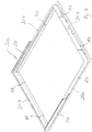
- the frame structure in Fig. 1 is a window frame 1 having two side pieces 1a, a bottom piece 1b and a top piece 1c.
- the structure of the individual frame pieces may vary within the general principle underlying the invention, i.e. that a core including at least one core member formed from high density and/or high temperature expanded polystyrene (EPS) is encased in a polyurethane shell.
- EPS high temperature expanded polystyrene
- window frame is only an example, and that the invention applies to other profile element constructions, such as a window sash or a door frame.
- FIG. 2 a cross-sectional view of a window frame side piece 1a according to the invention can be seen.
- the side piece 1a comprises a core consisting of a core member 2 of high density EPS encapsulated in a shell in the form of a surface layer 3 formed of foamed polyurethane (PUR).
- PUR foamed polyurethane
- the cross-section shown in Fig. 2 comprises recesses 4 and 5 in the core member, which are not used at this position on the frame, but has a function elsewhere along the frame side piece, serving for example to receive screws. If opting for a side core piece with a non-constant cross sectional shape, these recesses could be replaced by local depressions in the core member(s).
- Another recess 6 is adapted for receiving a lining and is therefore not filled with the shell material.
- the ideal thickness of the PUR shell is a balance of integrity of the resulting frame structure, material cost, insulation properties etc.
- the PUR material is, however, relatively expensive, and the thickness should therefore be kept at a minimum, but practical problems relating to moulding of the plastic sets a lower value of about 1 mm.
- a suitable interval of the average thickness of the plastic material is 1 to 8 mm, preferably at least 2 mm and maximum 5 mm.
- the core is covered entirely by the PUR shell, but it is to be understood that there may be openings in the shell exposing the core without departing from the scope of the invention.
- the PUR material is preferably an integral PUR foam having a density of in the interval 100-800 kg/m 3 and good results has been achieved with a density of approximately 600 kg/m 3 .
- This foam provides a hard, robust, weather-proof and neat surface, which provides strength and stiffness and is easy to clean. If superior properties are needed a massive integral foam having a density in the interval 800-1200 kg/m 3 could be chosen.
- Fig. 3 depicts a cross-sectional view of the corner between the left side piece 1a and the top piece 1c of a window frame as the one in Fig. 1 , but in a different embodiment than the one shown in Fig. 2 .
- Elements having the same function as those already described with reference to Fig. 2 have been given the same reference numbers but with 100 added.
- the frame structure 1 here has a relatively complicated lay-out and is made up from a series of parts and materials, of which a varying number may be present depending on the requirements with regard to e.g. strength, stiffness and thermal insulation and which may vary over the length of the individual frame pieces.
- reinforcing elements are provided. These include two angle bars 40 and a U-shaped bar 50 provided at cross-sectional corners of the side piece 1a, whereas the top piece 1c is provided with two U-shaped bars 8, 9.
- the reinforcing angle bars 40 and U-shaped bars 50, 8, 9 may be provided adjacent the inner side of the outer shell 103 or, as presently preferred, embedded in the outer shell 103, but covered thereby, whereby the bars are invisible from the outside.
- the best results with regard to stiffness and strength is achieved when the reinforcing bars are arranged remote from a central axis 30 of the frame piece.
- the bars may extend in the full length of frame pieces 1a, 1b, 1c making up the frame, or cover only part of the length and may be mutually connected at the corners of the frame structure to further increase stiffness and strength.
- the bars 40, 50, 8, 9 may be made of metal or of a high-strength plastic and/or fibre material, possibly pultruded.
- the angle bars have a thickness of 1.5 mm and each leg of the angle has a length of 10 mm, whereas the U-shaped bars has a thickness of 1.5 mm, each leg has a length of 8 mm and the back has a length of 16 mm.
- the side piece 1a and the top piece 1c shown are further provided with inserts, the function of which is to further improve the stiffness and strength of the frame.
- the side piece 1a comprises an insert in the form of a plate element 60 anchored in a first anchor 7 and a second anchor 14, said anchors 7, 14 being in turn held by the U-shaped bar 50 and the angle bars 40.
- the insert may hence also provide a means to assemble and hold the reinforcing elements prior to and during moulding of the core 102 and the outer shell 103.
- the top piece 1c is provided with a plate element 17 anchored in anchors 15 and 16.
- the plate elements 17, 60 and the anchors 7, 14, 15, 16 may be made of metal or a plastic and/or fibre material, and the plate element and anchors need not be made of the same material.
- the inserts can, as shown, be assembled from separate parts or alternatively, the inserts may be of integral construction, such as an injection moulded or pultruded plastic bar. It is preferred that the inserts are embedded in the core 102 to avoid or at least reduce formation of thermal bridges. For the same reason the inserts may be positioned with spacers in relation to the outer shell and reinforcing elements, so that the inserts are completely surrounded by the core material.
- the inserts may extend over the whole length of the elements, but it is presently preferred to have such strengthening inserts only at corners of the frame structure, so that the inserts only extend to a limited distance from the frame corner.
- the corner area of the profile element construction may be reinforced by having integral webs or diagonal braces formed of the material of the outer shell.
- Additional inserts may be used to strengthen the construction at fittings, brackets and hinges.
- the frame may be provided with a slat 20, here shown only in the top frame piece 1c, which may be of wood, plywood or a suitable plastics material, to provide support for a striking plate and a firm basis to allow mounting of screws in the profile elements. Openings 22 or weakening are provided in the outer shell 103 to allow the insertions of such fasteners.
- Further slats 21 may be provided to allow mounting of screws, nails or other fastening means at other locations on the profile element construction, here in the side piece 1a. This may for example be convenient for mounting of linings or the like.
- the reinforcing slats 20, 21 or like elements may be separate elements or assembled to constitute a closed frame and they may extend along the entire length of the side and top pieces 1a, 1c.
- FIG. 4 Alternative means for allowing a secure attachment of different window parts, such as fittings, brackets, hinges, covering, claddings, shutters or the like, by means of screws or like fasteners 70 are shown in Fig. 4 .
- Detail A) at the top left corner shows the use of an insert 71 for receiving the screw or peg 70.
- the insert may serve only as a receiver preventing the screw or peg from being pulled out of the frame when affected by loads, but it may also serve to distribute the loads onto the frame material and/or a load-bearing structure.
- an insert of this type may have other functions, for example being an electrical conductor, and the fastener 70 may then be replaced by an electrical plug.
- the insert is shown as located slightly below the centre of the frame profile, which is an advantageous position when serving as a reinforcement for taking up bending loads, but is may also be located elsewhere and may even be in contact with the PUR shell.
- the shape of the insert may vary and bends or projections may be used for establishing a contact between the embedded insert and the outer surface of the frame. It is also to be understood that the frame profile may contain more than one insert, an example being the combination of one serving reinforcing purposes and another being an electrical conductor.
- Detail B shows the provision of a thickening 72 in the PUR layer, which gives the frame more strength and stiffness, thus for example making it better suited for the attachment of hinges. This way of attaching the screw or peg 70 has been described above and will not be explained in further detail here.
- Detail C) shows a hole 73 through the core, which has been partially filled with PUR as also described above and detail D) is a variation of the embodiment, where the hole in the EPS core has been lined with a pipe 731.
- the liner 731 decreases the friction between the EPS and the PUR and helps the PUR to flow into the hole in the intended manner.
- the hole may be formed during moulding of the EPS core member, for example by arranging a mandrel in the mould, or formed afterwards, for example by drilling or melting.
- Detail E shows a fifth embodiment, where the hole 732 through the EPS is still open so that a bolt 701 can be passed through it and be fixated on the opposite side by a nut 702.
- the PUR layer 721 penetrates some distance into the hole 732 from both sides, but does not meet to form a continuous structure reaching from one side to the other as in detail C).
- This has the advantage that the frame is capable of yielding slightly, when the bolt and nut connection is tightened or affected by loads, hence minimizing the risk of the PUR layer rupturing either at the bridging portions inside the hole or at the outer surface of the frame.
- the spaces between the ends of the PUR shell projecting into the hole is filled with EPS, but they may also be left open or filled with another compressible material. Shaping the parts of the PUR shell projecting into the hole may be achieved by using material that melts away or dissolves during the moulding of the PUR shell or by providing the EPS core with form parts made for example of thin plastic sheets, which may easily be penetrated afterwards if needed.
- Details F) and G) shows the provision of an insert 74,75, which projects through the PUR layer and has projecting flanges 741,751, which are secured underneath the PUR layer.
- an insert 74,75 may serve as an electrical connector and it may then be connected to an insert inside the profile as shown in detail A). This may for example be used for supplying energy to blinds, shutters, opening devices, rain sensors or the like.
- An example of a hinge device which could be connected to such an electrical system is described in WO2010/003426 .
- such combinations of inserts could be used for lighting, if using optical fibres instead of electrical conductors, or even for ventilation, if providing a system canals in the frame profile.
- a pocket hole in the core members has been covered by a layer of PUR on its inner side and an insert 78 has subsequently or simultaneously been inserted in the hole to receive the screw or peg 70.
- the insert has barbs 781 on its outer side preventing it from being pulled out. This may be achieved by letting the PUR material set around a stiff insert or by making the PUR with a profiled surface and then causing the insert to fill the recessed in this surface, the insert then possibly being made from a material, which hardens upon insertion.
- a similar insert 79 is shown in detail K), but here it is inserted in a block 791 of a different material provided in the core member and projecting underneath the PUR layer to prevent it from being pulled out.
- This block of material may be a stiff material or a setting material, such as glue, as described above.
- FIG. 5 an example of a core 202 for a frame structure according to the invention, here for use as a window sash, is shown prior to moulding of the PUR shell.
- this core 202 is formed from four core pieces 201a, 201b, 202c corresponding to the side, bottom and top pieces of the frame structure, respectively, and assembled at joints 181, 182, 183, 184.
- the material intended to serve as core in the outermost ends of the top and bottom frame pieces are here part of the core side pieces 201a.
- the same core side pieces 201a may be used for making sash frames for any window of a particular length, whereas the width may be varied by simply choosing different top and bottom core pieces.
- other shapes of the respective core members and hence the location of the joints between them may be more expedient.
- Each core piece may be composed of several core members as explained above.
- the striking bead 221 found on each of the side core pieces may be made separately and then attached to a less complex main side core member 224.
- the joints 181, 182, 183, 184 are made as dovetail joints, which means that the core members are temporarily kept together until fixated by the PUR shell, but other types of joints, including simple butt joints, may of course by used, just as glue, adhesive, clamps etc. may be used for a temporary fixation.
- the PUR shell is preferably applied by inserting the entire core in a PUR mould and then moulding the PUR shell around the core.
- the frame structure 1 may be manufactured by first moulding the outer shell 3, 103, possibly as two half-shells, with embedded reinforcing elements if needed and then filling the cavity with EPS.
- Fig. 6 shows an alternative embodiment of a core for a frame structure according to the invention, here intended for a window frame.
- the frame core is assembled of straight core pieces 301a, 301b, 301c having uniform cross-section along the length thereof.
- EPS is dark coloured due to the addition of a fire-retardant and other functional additives, such as for example a UV-stabilizer, may also be used depending on demands.
- a fire-retardant such as for example a UV-stabilizer
- auxiliary wedge parts 13 are provided to strengthen the joint and provide a smooth transition between the side and bottom members.
- the wedge parts 13 are not necessarily made of EPS, but may be made of for example a polymer.
- FIG. 7 Yet another embodiment of an assembled core 402 for a frame structure, here for a window sash, can be seen in Fig. 7 .
- This core corresponds in shape to the one in Fig. 5 , but here the striking beads 421 are made as separate core members of a different material than main members 424 of the side core pieces 401a, which are of a substantially constant cross sectional shape. Additional core members 422, 423 and 425 are used at the bottom core piece 401b and top core piece 401c.
- the frame structure may be provided with a shielding arrangement.
- the shield may include a cladding 10 having a first part substantially parallel with the upper and outwards facing side and a second part substantially perpendicular to the first part.
- the second part of cladding covers the outwards and sidewards facing part of frame member.
- coverings members 11 are provided for covering the joint between the frame and a window sash (not shown).
- the shield may also include a flashing (not shown) comprising a first part along the outwards and sidewards facing side of core member and a second part substantially perpendicular to the first part and adapted to be positioned substantially in parallel with and below the roofing in the mounted position.
- Such cladding, covering and flashing parts may be attached to or embedded in the PUR shell.
- the profile element construction With the profile element construction according to the invention, a versatile construction is achieved, which can be tailor-made to the requirements of a specific use. Hence it is clear that the profile element construction can be used as a frame or sash for a window or door, and the construction can be adapted to the specific use e.g. by incorporating more reinforcing elements.
Landscapes
- Engineering & Computer Science (AREA)
- Civil Engineering (AREA)
- Structural Engineering (AREA)
- Wing Frames And Configurations (AREA)
- Laminated Bodies (AREA)
Abstract
Description
- The present invention relates to a frame structure, such as a window sash or a frame for a window or door, including side, top and bottom pieces, said frame structure comprising a core made from at least one core member and a shell of polyurethane encasing the core, and to a method for making such a frame structure.
- Traditional wooden frame structures are considered aesthetically pleasing but are not very robust, particularly not when exposed to moisture, and they lack the insulating properties wanted in modern buildings.
- The robustness issues have been solved with window frames made from polyvinylchloride (PVC), which is very widely used, while other window makers, including the applicant, have chosen to make the frames from profiles with a wooden core, typically of ply-wood, and a polyurethane (PUR) shell. Other plastic materials have also been used for the shell, but PUR is by far the most widely used, since it has suitable properties with regard to weather resistance, insulation, mouldability etc.
- These frames, however, still lack sufficient insulating properties to live up to the still stricter building regulations, which are being adopted in many countries, and it has therefore been attempted to include insulating materials in the frame structure. One example of this is the applicant's own prior patent application
WO2007/057029 , where the core is made at least partially of heat-treated wood, which has improved insulating properties; anotherDE19516486A1 , where the core is made from insulating foam. - In
DE19516486A1 the preferred insulating material was foamed PUR covered by a PUR shell and it was explained that the shell and the core should preferably be made from the same material to ease recycling. No other materials were mentioned and practice showed that very few other commercially available materials are in fact suitable for use in the core, and that most of these are way too costly for practical use. - As PUR too is a relatively expensive material, it is the object of the invention to provide an alternative and cheaper frame structure still having good thermal insulating properties.
- This is achieved with a frame structure where at least one core member is made from expanded polystyrene (EPS) with a density of 80-200 kg/m3, and where at least one joint between core members and/or core pieces of the frame structure is stabilized by polyurethane material having been allowed to flow into the gaps between the core members and/or core pieces, where it has sets, thus functioning as a glue.
- For a long time expanded polystyrene (EPS) has been considered unsuitable for use in moulded PUR frames. Firstly, the EPS tended to deteriorate by compression and melting and secondly the cores tended to get displaced in the mould during the moulding of the PUR shell.
- When working with the present invention, it was, however, surprisingly shown that the EPS could be made with a much higher density than what has previously been possible within reasonable economic limits and that such an extremely high density EPS is in fact suitable for use in frames with a PUR shell. A density interval of approximately 100-200 kg/m3 and more specifically 120-170 kg/m3 proved to provide a particularly good balance between insulating properties, costs and manageability, and a density of approximately 150-160 kg/m3 is presently considered advantageous. It is noted that the density need not be constant across the core member, but that one or more core members may includes zones of different density expanded polystyrene. As an example an outer layer may have a density of approximately 150 kg/m3 and a centre a density of approximately 100 kg/m3. The transition between such zones may be well defined, but due to the nature of EPS it will normally be expedient to have a gradual variation of the density, meaning that at least a part of the cross-section of the core member is characterized by a smooth increase and/or decrease in the EPS density.
- It has also been discovered that the addition of additives, such as polyphenylether, to the polystyrene can make the EPS material more resistant to high temperatures. Such materials, which are known as High Temperature EPS or EPS HT, form a relatively hard outer layer and are therefore less sensitive to compression and melting than EPS without such additives. It is therefore possible to use core members with a somewhat lower density and hence EPS HT is particularly advantageous in core members with a density of 80-100 kg/m3.
- It is to be understood that even though the core may be made from several core members, some of which may be made from different materials, the core is advantageously made primarily from EPS, including EPS HT, and that, in its simplest form, the core may consist of only a single core member.
- It is presently preferred that at least 90% by volume of the core is made from EPS with a density of 80-200 kg/m3, but cores with at least 80% by volume or even 50% by volume also presents considerable advantages. Likewise, it is to be understood that different core members may be made of EPS with different densities, some for example being made with a density of 120 kg/m3 and others with a density of 150 kg/m3.
- In order to facilitate manufacture and allow an optimization of the properties of the core, it may be made from a plurality of core pieces, each of said core pieces including at least one core member formed from EPS. Conveniently, said plurality of core pieces may total four core pieces corresponding to the side, top and bottom pieces of the frame structure and the core pieces may then be given different properties corresponding to the different demands on the top, bottom and side frame pieces. As an example, additional core members in the form of metal brackets, polymer blocks or plugs and/or slats of plywood may be provided in the side core pieces at the intended location of window hinges to constitute a basis for fastening thereof and to transfer loads either to other parts of the frame structure or to a load-bearing structure, such as a roof structure. Other window components, such as a locking assembly, may also benefit from the provision of a non-EPS core member, which contributes to taking up loads.
- Examples of other possible materials are fibre glass, ceramics and wood- or plant-based materials, such as pine, chipboard, bamboo or hemp fibres, which have possibly been subjected to heat-treatment, acetylation or impregnation to avoid excessive humidification and/or deterioration. Such core members serving as inserts may also be embedded in the shell and/or be used to provide for example a base for mounting of auxiliary elements, such as striking plate and lining, and/or at the corners of the frame structure to strengthen the construction.
- Core members made from other materials than EPS may advantageously be inserted in or attached to an EPS core member prior to it being encased in polyurethane, possibly by the use of welding, adhesives or glue to provide a good interconnection. If the non-EPS has to be located at the centre of the cross-section of the finished frame or otherwise surrounded by EPS, two EPS core members may be sandwiched around it, but it also possible to embed such a core member in the EPS during making of the EPS core member. Alternatively, the non-EPS core member may be inserted in the core after encasement and possibly fixated by means of an adhesive or glue.
- The use of insert core members may be supplemented or even replaced by the shell having at least one section of increased thickness, which may provide the needed reinforcement for strength and/or attachment of hinges and fittings. Such sections of increased thickness may be achieved by making the core of at least one frame or sash piece with variations in its cross-sectional shape over the length of the frame or sash piece.
- The core members may be shaped by any suitable process, but the resulting outline or cross section of the core should preferably be relatively smooth with rounded edges to facilitate flow of the PUR, whereby the production time is reduced and a high quality coated frame structure may be achieved. Milling and sawing of the EPS materials inevitably results in some of the EPS beads being broken and left open and using a hot-wire for cutting is presently not feasible due to the high density. Therefore, it is presently preferred to shape the core members by moulding, preferably using hot water vapour.
- If choosing a design of the frame, which requires relatively large amounts of the PUR to be supplied to certain areas, it may also be advantageous to make the core members with holes or canals, which may then serve as high flow passages for the PUR. Such holes or canals should of course be provided with due consideration for the insulating properties and strength of the frame structure and will be filled wholly or partially with PUR, when the core is encased.
- Holes or canals in the core members may also be provided for use as points of attachment for fixing means such as screws or bolts used for example for mounting the window or for attaching other items such as hinges, cladding parts or shutters. As an example, a hole in the core member, which is filled with PUR as described above, may be used to receive screws driven into the frame structure, but it is also possible to provide a separate receiver, such as a Rawlplug® embedded in the core member and/or PUR. Other alternatives include the provision of holes, which stays open during moulding of the PUR, e.g. by being filled by a mandrel during the moulding, and allowing a bolt to pass through the frame structure or an expandable fastener to engage an undercut or widening in the hole.
- The provision of holes, which penetrate all the way through the core and which are filled wholly or partially with PUR, results in connections between the PUR layers of each side and may therefore be used for strengthening and/or stiffening purposes.
- The moulding process, which will not be described in detail here as it is known to skilled persons, consists in introducing EPS beads in a closed mould and applying pressure and heat, preferably by the introduction of hot water vapour. This applies both when the core is moulded in one piece and when core members are moulded separately.
- As an alternative to the use of hot water vapour the EPS beads may be interconnected by adhesion, for example by means of epoxy or an acrylic resin.
- This method of manufacture makes it possible for core members of a different material, such as for example a reinforcing metal profile, to be located in the centre of one or more core pieces, which would otherwise require the making of several EPS core members to be sandwiched around the insert.
- Joining of core members and/or core pieces of the frame structure may be accomplished by any suitable joining means, such as clamps, staples, welding, adhesives, glue etc., including epoxy or an acrylic resin. In an embodiment of the invention the core members are assembled with dovetail joints. Hereby the frame structure may be assembled quickly and with relative ease without need for special tools.
- Joints are stabilized by allowing the PUR material to flow into the gaps between the core members and/or core pieces, where it sets, thus functioning as a glue.
- As the joint is completely encased in PUR, the surface of the frame structure is closed and impervious making the frame structure weatherproof and robust.
- It is also possible to pre-treat the surface of the core member(s) with an adhesion promoting surface profiling or surface covering to facilitate adherence. This may be accomplished in a number of ways, such as by etching the surface of the mould used for making the core, by applying a suitable primer or the like. It is presently preferred to roughen the surface of the EPS to provide a surface having improved adherence characteristics, the roughening entailing an increase in the area of the contact surface between the core and the shell. Such roughening may for example be achieved by providing a mould used for making core members with a surface profiling, which may for example be done by photo etching. A zigzag pattern with a depth of approximately 1 mm in the surface of the core member has been shown to provide a good adherence of PUR.
- In the following the invention will be described in more detail by way of example and with reference to the drawing, in which:
-
Fig. 1 is a perspective view showing a window frame according to the invention; -
Fig. 2 is a cross-sectional view of a detail of the window frame along the line II-II inFig. 1 with cladding and coverings members etc. removed; -
Fig. 3 is a cross-sectional perspective view of a corner of a window frame as marked with the circle III inFig. 1 , but according to a second embodiment of the invention and with cladding and coverings members etc. removed; -
Fig. 4 is a series of partially cut-away cross-sectional sketches of different ways of securing a screw or peg to a frame structure, -
Fig. 5 is a perspective view showing a core of a window sash structure in a third embodiment of the invention; -
Fig. 6 is a side angle view photo of a core of a window frame prototype corresponding to a fourth embodiment of the invention; and -
Fig. 7 is a side angle view photo of a core of a window sash prototype corresponding to a fifth embodiment of the invention. - The frame structure in
Fig. 1 is awindow frame 1 having twoside pieces 1a, a bottom piece 1b and atop piece 1c. As will be described in further detail below, the structure of the individual frame pieces may vary within the general principle underlying the invention, i.e. that a core including at least one core member formed from high density and/or high temperature expanded polystyrene (EPS) is encased in a polyurethane shell. - It will be evident to the skilled person that the window frame is only an example, and that the invention applies to other profile element constructions, such as a window sash or a door frame.
- In the drawing of
Fig. 2 a cross-sectional view of a windowframe side piece 1a according to the invention can be seen. Theside piece 1a comprises a core consisting of acore member 2 of high density EPS encapsulated in a shell in the form of asurface layer 3 formed of foamed polyurethane (PUR). - The cross-section shown in
Fig. 2 comprisesrecesses 4 and 5 in the core member, which are not used at this position on the frame, but has a function elsewhere along the frame side piece, serving for example to receive screws. If opting for a side core piece with a non-constant cross sectional shape, these recesses could be replaced by local depressions in the core member(s). Anotherrecess 6 is adapted for receiving a lining and is therefore not filled with the shell material. - The ideal thickness of the PUR shell is a balance of integrity of the resulting frame structure, material cost, insulation properties etc. The PUR material is, however, relatively expensive, and the thickness should therefore be kept at a minimum, but practical problems relating to moulding of the plastic sets a lower value of about 1 mm. A suitable interval of the average thickness of the plastic material is 1 to 8 mm, preferably at least 2 mm and maximum 5 mm.
- In this embodiment the core is covered entirely by the PUR shell, but it is to be understood that there may be openings in the shell exposing the core without departing from the scope of the invention.
- The PUR material is preferably an integral PUR foam having a density of in the interval 100-800 kg/m3 and good results has been achieved with a density of approximately 600 kg/m3. This foam provides a hard, robust, weather-proof and neat surface, which provides strength and stiffness and is easy to clean. If superior properties are needed a massive integral foam having a density in the interval 800-1200 kg/m3 could be chosen.
- With regards to the EPS, good results were achieved with EPS foamed with pentane and moulded with water vapour to a density of approximately 120-150 kg/m3, 150 kg/m3 being presently preferred, and for high temperature EPS with a density of approximately 80-100 kg/m3.
-
Fig. 3 depicts a cross-sectional view of the corner between theleft side piece 1a and thetop piece 1c of a window frame as the one inFig. 1 , but in a different embodiment than the one shown inFig. 2 . Elements having the same function as those already described with reference toFig. 2 have been given the same reference numbers but with 100 added. - As can be seen, the
frame structure 1 here has a relatively complicated lay-out and is made up from a series of parts and materials, of which a varying number may be present depending on the requirements with regard to e.g. strength, stiffness and thermal insulation and which may vary over the length of the individual frame pieces. - As the
EPS core 102 has a relatively low strength and stiffness, reinforcing elements are provided. These include two angle bars 40 and aU-shaped bar 50 provided at cross-sectional corners of theside piece 1a, whereas thetop piece 1c is provided with two U-shaped bars 8, 9. The reinforcing angle bars 40 andU-shaped bars 50, 8, 9 may be provided adjacent the inner side of theouter shell 103 or, as presently preferred, embedded in theouter shell 103, but covered thereby, whereby the bars are invisible from the outside. The best results with regard to stiffness and strength is achieved when the reinforcing bars are arranged remote from acentral axis 30 of the frame piece. The bars may extend in the full length offrame pieces - The
bars - The
side piece 1a and thetop piece 1c shown are further provided with inserts, the function of which is to further improve the stiffness and strength of the frame. Theside piece 1a comprises an insert in the form of aplate element 60 anchored in afirst anchor 7 and asecond anchor 14, saidanchors U-shaped bar 50 and the angle bars 40. The insert may hence also provide a means to assemble and hold the reinforcing elements prior to and during moulding of thecore 102 and theouter shell 103. Similarly, thetop piece 1c is provided with aplate element 17 anchored inanchors plate elements anchors core 102 to avoid or at least reduce formation of thermal bridges. For the same reason the inserts may be positioned with spacers in relation to the outer shell and reinforcing elements, so that the inserts are completely surrounded by the core material. The inserts may extend over the whole length of the elements, but it is presently preferred to have such strengthening inserts only at corners of the frame structure, so that the inserts only extend to a limited distance from the frame corner. Alternatively, the corner area of the profile element construction may be reinforced by having integral webs or diagonal braces formed of the material of the outer shell. - Additional inserts (not shown) may be used to strengthen the construction at fittings, brackets and hinges.
- Optionally the frame may be provided with a
slat 20, here shown only in thetop frame piece 1c, which may be of wood, plywood or a suitable plastics material, to provide support for a striking plate and a firm basis to allow mounting of screws in the profile elements.Openings 22 or weakening are provided in theouter shell 103 to allow the insertions of such fasteners. -
Further slats 21 may be provided to allow mounting of screws, nails or other fastening means at other locations on the profile element construction, here in theside piece 1a. This may for example be convenient for mounting of linings or the like. - The reinforcing
slats top pieces - Alternative means for allowing a secure attachment of different window parts, such as fittings, brackets, hinges, covering, claddings, shutters or the like, by means of screws or like
fasteners 70 are shown inFig. 4 . - Detail A) at the top left corner shows the use of an
insert 71 for receiving the screw or peg 70. The insert may serve only as a receiver preventing the screw or peg from being pulled out of the frame when affected by loads, but it may also serve to distribute the loads onto the frame material and/or a load-bearing structure. Alternatively, or as a supplement, an insert of this type may have other functions, for example being an electrical conductor, and thefastener 70 may then be replaced by an electrical plug. Here the insert is shown as located slightly below the centre of the frame profile, which is an advantageous position when serving as a reinforcement for taking up bending loads, but is may also be located elsewhere and may even be in contact with the PUR shell. Likewise, the shape of the insert may vary and bends or projections may be used for establishing a contact between the embedded insert and the outer surface of the frame. It is also to be understood that the frame profile may contain more than one insert, an example being the combination of one serving reinforcing purposes and another being an electrical conductor. - Detail B) shows the provision of a thickening 72 in the PUR layer, which gives the frame more strength and stiffness, thus for example making it better suited for the attachment of hinges. This way of attaching the screw or peg 70 has been described above and will not be explained in further detail here.
- Detail C) shows a
hole 73 through the core, which has been partially filled with PUR as also described above and detail D) is a variation of the embodiment, where the hole in the EPS core has been lined with apipe 731. Theliner 731 decreases the friction between the EPS and the PUR and helps the PUR to flow into the hole in the intended manner. The hole may be formed during moulding of the EPS core member, for example by arranging a mandrel in the mould, or formed afterwards, for example by drilling or melting. - Detail E) shows a fifth embodiment, where the
hole 732 through the EPS is still open so that abolt 701 can be passed through it and be fixated on the opposite side by anut 702. As may be seen, thePUR layer 721 penetrates some distance into thehole 732 from both sides, but does not meet to form a continuous structure reaching from one side to the other as in detail C). This has the advantage that the frame is capable of yielding slightly, when the bolt and nut connection is tightened or affected by loads, hence minimizing the risk of the PUR layer rupturing either at the bridging portions inside the hole or at the outer surface of the frame. In detail E) the spaces between the ends of the PUR shell projecting into the hole is filled with EPS, but they may also be left open or filled with another compressible material. Shaping the parts of the PUR shell projecting into the hole may be achieved by using material that melts away or dissolves during the moulding of the PUR shell or by providing the EPS core with form parts made for example of thin plastic sheets, which may easily be penetrated afterwards if needed. - Details F) and G) shows the provision of an
insert insert WO2010/003426 . Moreover, such combinations of inserts could be used for lighting, if using optical fibres instead of electrical conductors, or even for ventilation, if providing a system canals in the frame profile. - Details H) and I) show corresponding inserts 76,77 of a slightly more complex design, resembling the plugs commonly used when attaching screws to walls. These plugs have threadlike flanges 761,771 on the outer sides contributing even further to prevent them from being pulled out and an inner lumen 762,772 designed to give room for the screw or peg 70 thus enabling the use of stiffer material than in details F) and G). The threading means that these inserts may be screwed into the core member.
- In detail J) a pocket hole in the core members has been covered by a layer of PUR on its inner side and an insert 78 has subsequently or simultaneously been inserted in the hole to receive the screw or peg 70. As may be seen, the insert has barbs 781 on its outer side preventing it from being pulled out. This may be achieved by letting the PUR material set around a stiff insert or by making the PUR with a profiled surface and then causing the insert to fill the recessed in this surface, the insert then possibly being made from a material, which hardens upon insertion.
- A
similar insert 79 is shown in detail K), but here it is inserted in ablock 791 of a different material provided in the core member and projecting underneath the PUR layer to prevent it from being pulled out. This block of material may be a stiff material or a setting material, such as glue, as described above. - It is to be understood that the embodiments shown in the details of
Fig. 4 may be combined so that two or more of them occur in the same frame and that they may even be found at the same location on the frame, an example being that an insert as shown in detail A) may be found underneath a thickening of the PUR layer as shown in detail B). - Turning now to
Fig. 5 , an example of acore 202 for a frame structure according to the invention, here for use as a window sash, is shown prior to moulding of the PUR shell. As may be seen thiscore 202 is formed from four core pieces 201a, 201b, 202c corresponding to the side, bottom and top pieces of the frame structure, respectively, and assembled atjoints - Each core piece may be composed of several core members as explained above. As an example, the
striking bead 221 found on each of the side core pieces may be made separately and then attached to a less complex mainside core member 224. - In
Fig. 5 thejoints - It is of course also possible to make the
core - The PUR shell is preferably applied by inserting the entire core in a PUR mould and then moulding the PUR shell around the core. Alternatively, the
frame structure 1 may be manufactured by first moulding theouter shell -
Fig. 6 shows an alternative embodiment of a core for a frame structure according to the invention, here intended for a window frame. The frame core is assembled ofstraight core pieces - Here the EPS is dark coloured due to the addition of a fire-retardant and other functional additives, such as for example a UV-stabilizer, may also be used depending on demands.
- At the lowermost corner joints
auxiliary wedge parts 13 are provided to strengthen the joint and provide a smooth transition between the side and bottom members. Thewedge parts 13 are not necessarily made of EPS, but may be made of for example a polymer. - Yet another embodiment of an assembled
core 402 for a frame structure, here for a window sash, can be seen inFig. 7 . This core corresponds in shape to the one inFig. 5 , but here thestriking beads 421 are made as separate core members of a different material thanmain members 424 of the side core pieces 401a, which are of a substantially constant cross sectional shape.Additional core members - In a manner known to the skilled person and illustrated in
Fig. 1 , the frame structure may be provided with a shielding arrangement. The shield may include acladding 10 having a first part substantially parallel with the upper and outwards facing side and a second part substantially perpendicular to the first part. Thus, the second part of cladding covers the outwards and sidewards facing part of frame member. In addition, coverings members 11 are provided for covering the joint between the frame and a window sash (not shown). The shield may also include a flashing (not shown) comprising a first part along the outwards and sidewards facing side of core member and a second part substantially perpendicular to the first part and adapted to be positioned substantially in parallel with and below the roofing in the mounted position. Such cladding, covering and flashing parts may be attached to or embedded in the PUR shell. - Considering the relatively low melting point of polystyrene, recycling of the materials use for the frame is relatively unproblematic. When using EPS without high temperature additives, the frame pieces can simply be heated to a temperature of approximately 200°C, where the polystyrene will have melted and can be separated from the polyurethane, which maintains it shape at this temperature.
- With the profile element construction according to the invention, a versatile construction is achieved, which can be tailor-made to the requirements of a specific use. Hence it is clear that the profile element construction can be used as a frame or sash for a window or door, and the construction can be adapted to the specific use e.g. by incorporating more reinforcing elements.
Claims (17)
- A frame structure, such as a window sash or a frame for a window or door, including side, top and bottom pieces, said frame structure comprising a core made from at least one core member and a shell of polyurethane encasing the core, characterized in that at least one core member is made from expanded polystyrene (EPS) with a density of 80-200 kg/m3, and in that at least one joint between core members and/or core pieces of the frame structure is stabilized by polyurethane material having been allowed to flow into the gaps between the core members and/or core pieces, where it has sets, thus functioning as a glue.
- A frame structure according to claim 1, wherein core members and/or core pieces of the frame structure are joined by clamps, staples, welding, adhesives, glue etc., including epoxy or an acrylic resin.
- A frame structure according to claim 1 or 2, wherein holes or canals in the core members, which have been filled wholly or partially with polyurethane when the core was encased, are provided for use as points of attachment for fixing means such as screws or bolts.
- A frame structure according to one or more of the preceding claims, wherein the density of the expanded polystyrene is approximately 100-200 kg/m3, preferably 120-170 kg/m3, and still more preferred approximately 150-160 kg/m3.
- A frame structure according to one or more of the preceding claims, wherein at least one core member is made from a high temperature expanded polystyrene (EPS HT) with a density of approximately 80-100 kg/m3.
- A frame structure according to any of the preceding claims, wherein at least one core member includes zones of different density expanded polystyrene.
- A frame structure according to any of the preceding claims, wherein at least 50% by volume, more preferred at least 80% by volume and still more preferred at least 90% by volume of the core is made from expanded polystyrene with a density of 80-200 kg/m3.
- A frame structure according to any of the preceding claims, wherein the core includes a plurality of core members formed from expanded polystyrene, and/or wherein the core is composed of separate core pieces each formed of at least one core member, preferably four separate core pieces corresponding to the side, top and bottom pieces of the frame structure, and/or wherein the cross-sectional shape of the core of at least one frame or sash piece varies over the length of the frame or sash piece.
- A frame structure according to any of the preceding claims, wherein at least one core member is made from a different material than expanded polystyrene, such as metal, fibre glass, ceramics, wood- or plant-based materials, polymers, which may possibly be fibre reinforced, other composites, and combinations thereof, one core member made from a different material than expanded polystyrene possibly constituting a basis for fastening of a hinge, a locking assembly or the like.
- A frame structure according to any of the preceding claims, wherein the shell has at least one section of increased thickness.
- A frame structure according to any of claims 8-10, wherein at least two core members made from expanded polystyrene are assembled in a dovetail joint.
- A frame structure according to any of the preceding claims, wherein at least one core member has an adhesion promoting surface profiling or surface covering.
- A method for making a frame structure according to any of claims 1-12, comprising the steps of:providing a core including at least one core member, andencasing the core in a shell of polyurethane,characterized in that at least one core member is made from expanded polystyrene with a density of 80-200 kg/m3, and in that at least one joint between core members and/or core pieces of the frame structure is stabilized by allowing the PUR material to flow into the gaps between the core members and/or core pieces, where it sets, thus functioning as a glue.
- A method according to claim 13, wherein the core includes one or more holes or canals intended to serve as high flow passages for the polyurethane, one or more holes or canals in at least one core member preferably being filled wholly or partially with polyurethane, when the core is encased.
- A method according to claim 13 or 14, wherein the expanded polystyrene core member(s) is/are shaped by arranging expanded polystyrene beads in a mould and applying heated water vapour.
- A method according to one or more of claims 13-15, wherein core members made from a different material than expanded polystyrene is embedded in an expanded polystyrene core member during making thereof, inserted in or attached to an expanded polystyrene core member prior to it being encased in polyurethane, or inserted in the core after encasement.
- A method according to any of claims 13-16, wherein, prior to being encased in the polyurethane shell, at least two core members are joined by means of dovetails, clamps, staples, welding, adhesives, glue or combinations thereof, including epoxy or an acrylic resin.
Priority Applications (1)
| Application Number | Priority Date | Filing Date | Title |
|---|---|---|---|
| PL18184664T PL3415705T3 (en) | 2012-05-11 | 2013-05-10 | A frame structure for a window and a method for making a frame structure |
Applications Claiming Priority (4)
| Application Number | Priority Date | Filing Date | Title |
|---|---|---|---|
| DKPA201270243 | 2012-05-11 | ||
| PCT/DK2013/050141 WO2013167144A1 (en) | 2012-05-11 | 2013-05-10 | A frame structure for a window and a method for making a frame structure |
| EP13722985.2A EP2847408B1 (en) | 2012-05-11 | 2013-05-10 | A frame structure for a window and a method for making a frame structure |
| EP16175246.4A EP3112574B1 (en) | 2012-05-11 | 2013-05-10 | A frame structure for a window and a method for making a frame structure |
Related Parent Applications (2)
| Application Number | Title | Priority Date | Filing Date |
|---|---|---|---|
| EP16175246.4A Division EP3112574B1 (en) | 2012-05-11 | 2013-05-10 | A frame structure for a window and a method for making a frame structure |
| EP13722985.2A Division EP2847408B1 (en) | 2012-05-11 | 2013-05-10 | A frame structure for a window and a method for making a frame structure |
Publications (2)
| Publication Number | Publication Date |
|---|---|
| EP3415705A1 true EP3415705A1 (en) | 2018-12-19 |
| EP3415705B1 EP3415705B1 (en) | 2020-02-19 |
Family
ID=48446024
Family Applications (3)
| Application Number | Title | Priority Date | Filing Date |
|---|---|---|---|
| EP18184664.3A Active EP3415705B1 (en) | 2012-05-11 | 2013-05-10 | A frame structure for a window and a method for making a frame structure |
| EP13722985.2A Active EP2847408B1 (en) | 2012-05-11 | 2013-05-10 | A frame structure for a window and a method for making a frame structure |
| EP16175246.4A Active EP3112574B1 (en) | 2012-05-11 | 2013-05-10 | A frame structure for a window and a method for making a frame structure |
Family Applications After (2)
| Application Number | Title | Priority Date | Filing Date |
|---|---|---|---|
| EP13722985.2A Active EP2847408B1 (en) | 2012-05-11 | 2013-05-10 | A frame structure for a window and a method for making a frame structure |
| EP16175246.4A Active EP3112574B1 (en) | 2012-05-11 | 2013-05-10 | A frame structure for a window and a method for making a frame structure |
Country Status (10)
| Country | Link |
|---|---|
| US (1) | US10119328B2 (en) |
| EP (3) | EP3415705B1 (en) |
| JP (1) | JP3199450U (en) |
| CN (1) | CN204703682U (en) |
| CA (1) | CA2869715C (en) |
| EA (1) | EA031550B1 (en) |
| ES (1) | ES2691419T3 (en) |
| HU (1) | HUE041532T2 (en) |
| PL (3) | PL3415705T3 (en) |
| WO (1) | WO2013167144A1 (en) |
Cited By (1)
| Publication number | Priority date | Publication date | Assignee | Title |
|---|---|---|---|---|
| EP3795772A1 (en) | 2020-02-03 | 2021-03-24 | VKR Holding A/S | A skylight window for being installed in a roof of a building |
Families Citing this family (18)
| Publication number | Priority date | Publication date | Assignee | Title |
|---|---|---|---|---|
| ITPS20140014A1 (en) * | 2014-10-24 | 2016-04-24 | Angelo Candiracci | PRODUCTION PROCESS OF PREFABRICATED PANELS AND DRUMS FOR THE FURNITURE INDUSTRY AND PRODUCTS WITH THIS PROCESS OBTAINED |
| DK178577B1 (en) * | 2014-12-23 | 2016-07-11 | Vkr Holding As | A frame structure, such as a sash or a stationary frame for a window or door, and a method for manufacturing a frame structure |
| EP3336295A1 (en) | 2016-12-16 | 2018-06-20 | Modulotherm Sp. z o.o. | Profile widening a window or door |
| CZ307469B6 (en) * | 2016-12-22 | 2018-09-26 | České vysoké učenà technické v Praze | A profile for the production of exterior frames and frames of roof window casements, and the use of this profile |
| PL240843B1 (en) * | 2016-12-24 | 2022-06-13 | Ergo Plus Polska Spolka Z Ograniczona Odpowiedzialnoscia | Frame beam of windows, doors and facades and method for producing the frame beam of windows, doors and facades |
| WO2018121830A1 (en) * | 2016-12-29 | 2018-07-05 | Vkr Holding A/S | A pane module adapted to be installed on a window frame and a method for making a pane module |
| US10295248B2 (en) | 2017-01-09 | 2019-05-21 | Electrolux Home Products, Inc. | Refrigerator with glass door |
| DK179723B1 (en) * | 2017-02-15 | 2019-04-12 | Vkr Holding A/S | A method for attaching a pane element to a sash and a pane module including a pane element |
| US11584041B2 (en) | 2018-04-20 | 2023-02-21 | Pella Corporation | Reinforced pultrusion member and method of making |
| US11371280B2 (en) | 2018-04-27 | 2022-06-28 | Pella Corporation | Modular frame design |
| US11015339B2 (en) | 2019-03-25 | 2021-05-25 | Old Mill Brick Llc | Fire resistant construction block |
| CA3097138C (en) | 2019-10-28 | 2024-01-16 | Pella Corporation | Integrated sash assembly |
| IT202000021613A1 (en) * | 2020-09-11 | 2022-03-11 | Alfa Holding Di Annarita Caponi E C Sas | METHOD FOR THE PRODUCTION OF A FURNITURE |
| US12098557B2 (en) | 2020-09-18 | 2024-09-24 | Old Mill Brick Llc | Panel for stones and related methods of use |
| EP4105429A1 (en) * | 2021-06-16 | 2022-12-21 | Salamander Industrie-Produkte GmbH | Coextrusion profile, method for producing a coextrusion profile and door and / or window system |
| US11761258B1 (en) * | 2022-02-04 | 2023-09-19 | Quantum Holdings Llc | Insulated window and door opening assemblies with high-density insulating cores |
| PL248507B1 (en) * | 2022-05-18 | 2025-12-22 | Fakro Pp Spolka Z Ograniczona Odpowiedzialnoscia | Window frame with corners |
| DE102024105593A1 (en) * | 2024-02-28 | 2025-08-28 | Tesa Se | Modular unit for a frame unit of a frame device, frame device and protection system |
Citations (7)
| Publication number | Priority date | Publication date | Assignee | Title |
|---|---|---|---|---|
| DE19516486A1 (en) | 1995-05-05 | 1996-11-07 | Fingerling Karl Heinz | Window profile made from plastic material |
| DE29718915U1 (en) * | 1997-09-30 | 1998-01-22 | Pazen, Günter, 54492 Zeltingen-Rachtig | Frame profiles for the production of frames or casements for windows or doors |
| DE19853212A1 (en) * | 1998-11-18 | 2000-05-25 | Thomas Goetz | EPS foam molding contains embedded fittings offering e.g. points of attachment for built-in furniture door, with improved mechanical- and handling properties |
| WO2007057029A1 (en) | 2005-11-21 | 2007-05-24 | Vkr Holding A/S | A frame structure and a method for manufacturing such a frame structure |
| WO2010003426A1 (en) | 2008-07-10 | 2010-01-14 | Vkr Holding A/S | A pivot window with electrical hinge connection |
| WO2010088905A1 (en) * | 2009-02-03 | 2010-08-12 | Vkr Holding A/S | A method of making a window frame unit with a pane |
| WO2013050045A1 (en) * | 2011-10-04 | 2013-04-11 | Vkr Holding A/S | A roof window with improved striking bead covering |
Family Cites Families (25)
| Publication number | Priority date | Publication date | Assignee | Title |
|---|---|---|---|---|
| US3111569A (en) * | 1958-06-20 | 1963-11-19 | Rubenstein David | Packaged laminated constructions |
| GB1140261A (en) * | 1964-04-29 | 1969-01-15 | Elisa Berthelsen | Improvements in and relating to structural frames such as window frames |
| US4130976A (en) * | 1977-03-07 | 1978-12-26 | Gerbruder Kommerling Kunststoffwerke G.M.B.H. | Frame for doors, windows and the like |
| US4327142A (en) * | 1978-12-06 | 1982-04-27 | Vittorio Norzi | Method of manufacturing goods of laminates and goods so manufactured |
| US4720951A (en) * | 1986-03-24 | 1988-01-26 | Therma-Tru Corp. | Frame assembly for doors, windows and the like |
| US5142835A (en) * | 1990-10-12 | 1992-09-01 | Taylor Building Products Company | Reaction injection molded door assembly |
| US5602188A (en) * | 1993-07-13 | 1997-02-11 | Suzuki Sogyo Co., Ltd. | Biodegradable resin foam and method and apparatus for producing same |
| NZ281536A (en) * | 1994-03-04 | 1998-03-25 | Armacel Pty Ltd | Laminating a thermoplastics sheet onto an inner fluid permeable member wherein a fluid pressure differential between the sheet and member is maintained until the sheet has cooled |
| CA2140162A1 (en) * | 1995-01-13 | 1996-07-14 | Materiaux De Construction 2 Plus 2 Inc. | Modular anti-warping door structure |
| DE19546678C2 (en) | 1995-12-15 | 2003-06-05 | Eurotec Gmbh | Profiled window or door |
| US5899026A (en) * | 1997-09-29 | 1999-05-04 | Williams; Mark F. | Multi-component elastomeric materials for a building flashing system |
| US6619005B1 (en) * | 2002-04-16 | 2003-09-16 | Kuei Yung Wang Chen | Molded doors with large glass insert |
| US7178308B2 (en) * | 2002-06-28 | 2007-02-20 | Masonite International Corporation | Composite door structure and method of forming a composite door structure |
| US6927183B1 (en) * | 2002-09-04 | 2005-08-09 | Diversitech Corporation | Reinforced article |
| US7185468B2 (en) * | 2002-10-31 | 2007-03-06 | Jeld-Wen, Inc. | Multi-layered fire door and method for making the same |
| US20050281999A1 (en) * | 2003-03-12 | 2005-12-22 | Petritech, Inc. | Structural and other composite materials and methods for making same |
| US20060101735A1 (en) * | 2004-09-29 | 2006-05-18 | Silver Line Building Products Corp. | Integrally reinforced plastic molded components and products |
| DE102008009495A1 (en) | 2008-02-15 | 2009-08-20 | Bbg Gmbh & Co. Kg | A method of manufacturing a molding, molding tool for use in the method and profile molding produced by the method |
| EP2394013B1 (en) * | 2009-02-03 | 2019-10-30 | VKR Holding A/S | A window having a sash and an improved connection to the hinge |
| GB0922112D0 (en) * | 2009-05-22 | 2010-02-03 | Oldcastle Apg Inc | Building block and cladding system |
| US8889752B2 (en) * | 2010-06-11 | 2014-11-18 | Fina Technology, Inc. | Foamed articles exhibiting improved thermal properties |
| CN103502336B (en) * | 2011-04-04 | 2016-05-11 | 株式会社Yetoo | Froth pulp, floating structure and building materials thereof |
| US9420891B2 (en) * | 2013-11-29 | 2016-08-23 | Zinus, Inc. | Foam furniture molded around a rigid foam core |
| US9456696B2 (en) * | 2013-11-29 | 2016-10-04 | Zinus, Inc. | Foam furniture molded around a core with a lumbar support protrusion |
| US8938927B1 (en) * | 2014-06-18 | 2015-01-27 | McElroy Metal Mill, Inc. | Horizontally oriented insulated metal panel siding system |
-
2013
- 2013-05-10 PL PL18184664T patent/PL3415705T3/en unknown
- 2013-05-10 WO PCT/DK2013/050141 patent/WO2013167144A1/en not_active Ceased
- 2013-05-10 EP EP18184664.3A patent/EP3415705B1/en active Active
- 2013-05-10 ES ES16175246.4T patent/ES2691419T3/en active Active
- 2013-05-10 PL PL16175246T patent/PL3112574T3/en unknown
- 2013-05-10 CA CA2869715A patent/CA2869715C/en active Active
- 2013-05-10 EP EP13722985.2A patent/EP2847408B1/en active Active
- 2013-05-10 HU HUE16175246A patent/HUE041532T2/en unknown
- 2013-05-10 CN CN201390000473.0U patent/CN204703682U/en not_active Expired - Lifetime
- 2013-05-10 JP JP2015600020U patent/JP3199450U/en not_active Expired - Lifetime
- 2013-05-10 PL PL13722985.2T patent/PL2847408T3/en unknown
- 2013-05-10 EP EP16175246.4A patent/EP3112574B1/en active Active
- 2013-05-10 EA EA201401124A patent/EA031550B1/en not_active IP Right Cessation
- 2013-05-10 US US14/400,256 patent/US10119328B2/en active Active
Patent Citations (7)
| Publication number | Priority date | Publication date | Assignee | Title |
|---|---|---|---|---|
| DE19516486A1 (en) | 1995-05-05 | 1996-11-07 | Fingerling Karl Heinz | Window profile made from plastic material |
| DE29718915U1 (en) * | 1997-09-30 | 1998-01-22 | Pazen, Günter, 54492 Zeltingen-Rachtig | Frame profiles for the production of frames or casements for windows or doors |
| DE19853212A1 (en) * | 1998-11-18 | 2000-05-25 | Thomas Goetz | EPS foam molding contains embedded fittings offering e.g. points of attachment for built-in furniture door, with improved mechanical- and handling properties |
| WO2007057029A1 (en) | 2005-11-21 | 2007-05-24 | Vkr Holding A/S | A frame structure and a method for manufacturing such a frame structure |
| WO2010003426A1 (en) | 2008-07-10 | 2010-01-14 | Vkr Holding A/S | A pivot window with electrical hinge connection |
| WO2010088905A1 (en) * | 2009-02-03 | 2010-08-12 | Vkr Holding A/S | A method of making a window frame unit with a pane |
| WO2013050045A1 (en) * | 2011-10-04 | 2013-04-11 | Vkr Holding A/S | A roof window with improved striking bead covering |
Cited By (2)
| Publication number | Priority date | Publication date | Assignee | Title |
|---|---|---|---|---|
| EP3795772A1 (en) | 2020-02-03 | 2021-03-24 | VKR Holding A/S | A skylight window for being installed in a roof of a building |
| EP3859094A1 (en) | 2020-02-03 | 2021-08-04 | VKR Holding A/S | A skylight window for being installed in a roof of a building |
Also Published As
| Publication number | Publication date |
|---|---|
| US20150096257A1 (en) | 2015-04-09 |
| WO2013167144A1 (en) | 2013-11-14 |
| EP2847408A1 (en) | 2015-03-18 |
| PL3415705T3 (en) | 2020-07-13 |
| PL2847408T3 (en) | 2016-12-30 |
| JP3199450U (en) | 2015-08-27 |
| EP3415705B1 (en) | 2020-02-19 |
| PL3112574T3 (en) | 2018-12-31 |
| EP3112574B1 (en) | 2018-08-01 |
| CN204703682U (en) | 2015-10-14 |
| US10119328B2 (en) | 2018-11-06 |
| EA031550B1 (en) | 2019-01-31 |
| CA2869715A1 (en) | 2013-11-14 |
| EA201401124A1 (en) | 2015-08-31 |
| EP2847408B1 (en) | 2016-06-22 |
| HUE041532T2 (en) | 2019-05-28 |
| EP3112574A1 (en) | 2017-01-04 |
| ES2691419T3 (en) | 2018-11-27 |
| CA2869715C (en) | 2016-11-08 |
Similar Documents
| Publication | Publication Date | Title |
|---|---|---|
| EP3415705B1 (en) | A frame structure for a window and a method for making a frame structure | |
| US8683694B1 (en) | Method of forming a frame assembly | |
| US6233892B1 (en) | Structural panel system | |
| US10378204B2 (en) | System for forming an insulated structural concrete wall | |
| CA2065955C (en) | Composite exterior door structure | |
| JPH10500746A (en) | Housing system with perforated hollow structural components | |
| EP3818219B1 (en) | Formwork cavity panel | |
| EP3280863B1 (en) | Construction frame defining an architectural opening during construction works; kit in parts comprising such construction frame and use of such construction frame | |
| DE102004011775A1 (en) | Lightweight rigid composite thermoplastic panel comprises facing layers welded onto both sides of a core filled with foam beads | |
| CN1062931C (en) | Building panel and buildings using the panel | |
| US20060070322A1 (en) | Constructional element and method for its manufacture | |
| KR101309734B1 (en) | door frame for prefabricating wall shaped mold unit | |
| EP0618989A1 (en) | Panel structure and panel for use in forming such structure. | |
| CN111622643B (en) | Fireproof and antitheft door and installation process thereof | |
| WO2008133528A1 (en) | Construction element, structural element thereof, and method for the manufacture of such elements | |
| CN117108176A (en) | A composite door leaf structure with foamed expansion buckle and tightening assembly | |
| NZ742082A (en) | Structural panels and methods of making and using such panels | |
| AU2018202979A1 (en) | Structural panels and methods of making and using such panels | |
| EP1608835A2 (en) | Thermally cut modular metal frame for doors and windows | |
| EP2003261A1 (en) | A modular construction element and a protective cap, and a method for assembling a plurality of modular construction elements using the cap | |
| ITPD980194A1 (en) | SHUTTERS FOR WINDOWS IN OVERLAPPING PANELS WITH INTERLOCKING COUPLING. | |
| AU2005203562A1 (en) | A wall panel and assembly therefor | |
| FR2596098A1 (en) | Process for attaching an insulating cladding to a wall, insulating plates for its implementation and their manufacturing processes |
Legal Events
| Date | Code | Title | Description |
|---|---|---|---|
| PUAI | Public reference made under article 153(3) epc to a published international application that has entered the european phase |
Free format text: ORIGINAL CODE: 0009012 |
|
| STAA | Information on the status of an ep patent application or granted ep patent |
Free format text: STATUS: THE APPLICATION HAS BEEN PUBLISHED |
|
| AC | Divisional application: reference to earlier application |
Ref document number: 2847408 Country of ref document: EP Kind code of ref document: P Ref document number: 3112574 Country of ref document: EP Kind code of ref document: P |
|
| AK | Designated contracting states |
Kind code of ref document: A1 Designated state(s): AL AT BE BG CH CY CZ DE DK EE ES FI FR GB GR HR HU IE IS IT LI LT LU LV MC MK MT NL NO PL PT RO RS SE SI SK SM TR |
|
| STAA | Information on the status of an ep patent application or granted ep patent |
Free format text: STATUS: REQUEST FOR EXAMINATION WAS MADE |
|
| 17P | Request for examination filed |
Effective date: 20190618 |
|
| RBV | Designated contracting states (corrected) |
Designated state(s): AL AT BE BG CH CY CZ DE DK EE ES FI FR GB GR HR HU IE IS IT LI LT LU LV MC MK MT NL NO PL PT RO RS SE SI SK SM TR |
|
| GRAP | Despatch of communication of intention to grant a patent |
Free format text: ORIGINAL CODE: EPIDOSNIGR1 |
|
| STAA | Information on the status of an ep patent application or granted ep patent |
Free format text: STATUS: GRANT OF PATENT IS INTENDED |
|
| INTG | Intention to grant announced |
Effective date: 20190905 |
|
| GRAS | Grant fee paid |
Free format text: ORIGINAL CODE: EPIDOSNIGR3 |
|
| GRAA | (expected) grant |
Free format text: ORIGINAL CODE: 0009210 |
|
| STAA | Information on the status of an ep patent application or granted ep patent |
Free format text: STATUS: THE PATENT HAS BEEN GRANTED |
|
| AC | Divisional application: reference to earlier application |
Ref document number: 3112574 Country of ref document: EP Kind code of ref document: P Ref document number: 2847408 Country of ref document: EP Kind code of ref document: P |
|
| AK | Designated contracting states |
Kind code of ref document: B1 Designated state(s): AL AT BE BG CH CY CZ DE DK EE ES FI FR GB GR HR HU IE IS IT LI LT LU LV MC MK MT NL NO PL PT RO RS SE SI SK SM TR |
|
| REG | Reference to a national code |
Ref country code: CH Ref legal event code: EP |
|
| REG | Reference to a national code |
Ref country code: DE Ref legal event code: R096 Ref document number: 602013066102 Country of ref document: DE |
|
| REG | Reference to a national code |
Ref country code: AT Ref legal event code: REF Ref document number: 1235147 Country of ref document: AT Kind code of ref document: T Effective date: 20200315 |
|
| REG | Reference to a national code |
Ref country code: IE Ref legal event code: FG4D |
|
| REG | Reference to a national code |
Ref country code: NL Ref legal event code: MP Effective date: 20200219 |
|
| PG25 | Lapsed in a contracting state [announced via postgrant information from national office to epo] |
Ref country code: NO Free format text: LAPSE BECAUSE OF FAILURE TO SUBMIT A TRANSLATION OF THE DESCRIPTION OR TO PAY THE FEE WITHIN THE PRESCRIBED TIME-LIMIT Effective date: 20200519 Ref country code: RS Free format text: LAPSE BECAUSE OF FAILURE TO SUBMIT A TRANSLATION OF THE DESCRIPTION OR TO PAY THE FEE WITHIN THE PRESCRIBED TIME-LIMIT Effective date: 20200219 Ref country code: FI Free format text: LAPSE BECAUSE OF FAILURE TO SUBMIT A TRANSLATION OF THE DESCRIPTION OR TO PAY THE FEE WITHIN THE PRESCRIBED TIME-LIMIT Effective date: 20200219 |
|
| REG | Reference to a national code |
Ref country code: LT Ref legal event code: MG4D |
|
| PG25 | Lapsed in a contracting state [announced via postgrant information from national office to epo] |
Ref country code: BG Free format text: LAPSE BECAUSE OF FAILURE TO SUBMIT A TRANSLATION OF THE DESCRIPTION OR TO PAY THE FEE WITHIN THE PRESCRIBED TIME-LIMIT Effective date: 20200519 Ref country code: IS Free format text: LAPSE BECAUSE OF FAILURE TO SUBMIT A TRANSLATION OF THE DESCRIPTION OR TO PAY THE FEE WITHIN THE PRESCRIBED TIME-LIMIT Effective date: 20200619 Ref country code: LV Free format text: LAPSE BECAUSE OF FAILURE TO SUBMIT A TRANSLATION OF THE DESCRIPTION OR TO PAY THE FEE WITHIN THE PRESCRIBED TIME-LIMIT Effective date: 20200219 Ref country code: SE Free format text: LAPSE BECAUSE OF FAILURE TO SUBMIT A TRANSLATION OF THE DESCRIPTION OR TO PAY THE FEE WITHIN THE PRESCRIBED TIME-LIMIT Effective date: 20200219 Ref country code: GR Free format text: LAPSE BECAUSE OF FAILURE TO SUBMIT A TRANSLATION OF THE DESCRIPTION OR TO PAY THE FEE WITHIN THE PRESCRIBED TIME-LIMIT Effective date: 20200520 Ref country code: HR Free format text: LAPSE BECAUSE OF FAILURE TO SUBMIT A TRANSLATION OF THE DESCRIPTION OR TO PAY THE FEE WITHIN THE PRESCRIBED TIME-LIMIT Effective date: 20200219 |
|
| PG25 | Lapsed in a contracting state [announced via postgrant information from national office to epo] |
Ref country code: NL Free format text: LAPSE BECAUSE OF FAILURE TO SUBMIT A TRANSLATION OF THE DESCRIPTION OR TO PAY THE FEE WITHIN THE PRESCRIBED TIME-LIMIT Effective date: 20200219 |
|
| PG25 | Lapsed in a contracting state [announced via postgrant information from national office to epo] |
Ref country code: ES Free format text: LAPSE BECAUSE OF FAILURE TO SUBMIT A TRANSLATION OF THE DESCRIPTION OR TO PAY THE FEE WITHIN THE PRESCRIBED TIME-LIMIT Effective date: 20200219 Ref country code: SK Free format text: LAPSE BECAUSE OF FAILURE TO SUBMIT A TRANSLATION OF THE DESCRIPTION OR TO PAY THE FEE WITHIN THE PRESCRIBED TIME-LIMIT Effective date: 20200219 Ref country code: SM Free format text: LAPSE BECAUSE OF FAILURE TO SUBMIT A TRANSLATION OF THE DESCRIPTION OR TO PAY THE FEE WITHIN THE PRESCRIBED TIME-LIMIT Effective date: 20200219 Ref country code: LT Free format text: LAPSE BECAUSE OF FAILURE TO SUBMIT A TRANSLATION OF THE DESCRIPTION OR TO PAY THE FEE WITHIN THE PRESCRIBED TIME-LIMIT Effective date: 20200219 Ref country code: PT Free format text: LAPSE BECAUSE OF FAILURE TO SUBMIT A TRANSLATION OF THE DESCRIPTION OR TO PAY THE FEE WITHIN THE PRESCRIBED TIME-LIMIT Effective date: 20200712 Ref country code: DK Free format text: LAPSE BECAUSE OF FAILURE TO SUBMIT A TRANSLATION OF THE DESCRIPTION OR TO PAY THE FEE WITHIN THE PRESCRIBED TIME-LIMIT Effective date: 20200219 Ref country code: RO Free format text: LAPSE BECAUSE OF FAILURE TO SUBMIT A TRANSLATION OF THE DESCRIPTION OR TO PAY THE FEE WITHIN THE PRESCRIBED TIME-LIMIT Effective date: 20200219 Ref country code: CZ Free format text: LAPSE BECAUSE OF FAILURE TO SUBMIT A TRANSLATION OF THE DESCRIPTION OR TO PAY THE FEE WITHIN THE PRESCRIBED TIME-LIMIT Effective date: 20200219 Ref country code: EE Free format text: LAPSE BECAUSE OF FAILURE TO SUBMIT A TRANSLATION OF THE DESCRIPTION OR TO PAY THE FEE WITHIN THE PRESCRIBED TIME-LIMIT Effective date: 20200219 |
|
| REG | Reference to a national code |
Ref country code: DE Ref legal event code: R097 Ref document number: 602013066102 Country of ref document: DE |
|
| PLBE | No opposition filed within time limit |
Free format text: ORIGINAL CODE: 0009261 |
|
| STAA | Information on the status of an ep patent application or granted ep patent |
Free format text: STATUS: NO OPPOSITION FILED WITHIN TIME LIMIT |
|
| 26N | No opposition filed |
Effective date: 20201120 |
|
| PG25 | Lapsed in a contracting state [announced via postgrant information from national office to epo] |
Ref country code: CH Free format text: LAPSE BECAUSE OF NON-PAYMENT OF DUE FEES Effective date: 20200531 Ref country code: IT Free format text: LAPSE BECAUSE OF FAILURE TO SUBMIT A TRANSLATION OF THE DESCRIPTION OR TO PAY THE FEE WITHIN THE PRESCRIBED TIME-LIMIT Effective date: 20200219 Ref country code: LI Free format text: LAPSE BECAUSE OF NON-PAYMENT OF DUE FEES Effective date: 20200531 Ref country code: MC Free format text: LAPSE BECAUSE OF FAILURE TO SUBMIT A TRANSLATION OF THE DESCRIPTION OR TO PAY THE FEE WITHIN THE PRESCRIBED TIME-LIMIT Effective date: 20200219 |
|
| PG25 | Lapsed in a contracting state [announced via postgrant information from national office to epo] |
Ref country code: SI Free format text: LAPSE BECAUSE OF FAILURE TO SUBMIT A TRANSLATION OF THE DESCRIPTION OR TO PAY THE FEE WITHIN THE PRESCRIBED TIME-LIMIT Effective date: 20200219 |
|
| PG25 | Lapsed in a contracting state [announced via postgrant information from national office to epo] |
Ref country code: LU Free format text: LAPSE BECAUSE OF NON-PAYMENT OF DUE FEES Effective date: 20200510 |
|
| PG25 | Lapsed in a contracting state [announced via postgrant information from national office to epo] |
Ref country code: IE Free format text: LAPSE BECAUSE OF NON-PAYMENT OF DUE FEES Effective date: 20200510 |
|
| REG | Reference to a national code |
Ref country code: AT Ref legal event code: UEP Ref document number: 1235147 Country of ref document: AT Kind code of ref document: T Effective date: 20200219 |
|
| PG25 | Lapsed in a contracting state [announced via postgrant information from national office to epo] |
Ref country code: TR Free format text: LAPSE BECAUSE OF FAILURE TO SUBMIT A TRANSLATION OF THE DESCRIPTION OR TO PAY THE FEE WITHIN THE PRESCRIBED TIME-LIMIT Effective date: 20200219 Ref country code: MT Free format text: LAPSE BECAUSE OF FAILURE TO SUBMIT A TRANSLATION OF THE DESCRIPTION OR TO PAY THE FEE WITHIN THE PRESCRIBED TIME-LIMIT Effective date: 20200219 Ref country code: CY Free format text: LAPSE BECAUSE OF FAILURE TO SUBMIT A TRANSLATION OF THE DESCRIPTION OR TO PAY THE FEE WITHIN THE PRESCRIBED TIME-LIMIT Effective date: 20200219 |
|
| PG25 | Lapsed in a contracting state [announced via postgrant information from national office to epo] |
Ref country code: MK Free format text: LAPSE BECAUSE OF FAILURE TO SUBMIT A TRANSLATION OF THE DESCRIPTION OR TO PAY THE FEE WITHIN THE PRESCRIBED TIME-LIMIT Effective date: 20200219 Ref country code: AL Free format text: LAPSE BECAUSE OF FAILURE TO SUBMIT A TRANSLATION OF THE DESCRIPTION OR TO PAY THE FEE WITHIN THE PRESCRIBED TIME-LIMIT Effective date: 20200219 |
|
| PGFP | Annual fee paid to national office [announced via postgrant information from national office to epo] |
Ref country code: AT Payment date: 20230425 Year of fee payment: 11 |
|
| PGFP | Annual fee paid to national office [announced via postgrant information from national office to epo] |
Ref country code: BE Payment date: 20230418 Year of fee payment: 11 |
|
| REG | Reference to a national code |
Ref country code: AT Ref legal event code: MM01 Ref document number: 1235147 Country of ref document: AT Kind code of ref document: T Effective date: 20240510 |
|
| PG25 | Lapsed in a contracting state [announced via postgrant information from national office to epo] |
Ref country code: AT Free format text: LAPSE BECAUSE OF NON-PAYMENT OF DUE FEES Effective date: 20240510 |
|
| PG25 | Lapsed in a contracting state [announced via postgrant information from national office to epo] |
Ref country code: AT Free format text: LAPSE BECAUSE OF NON-PAYMENT OF DUE FEES Effective date: 20240510 |
|
| REG | Reference to a national code |
Ref country code: BE Ref legal event code: MM Effective date: 20240531 |
|
| PG25 | Lapsed in a contracting state [announced via postgrant information from national office to epo] |
Ref country code: BE Free format text: LAPSE BECAUSE OF NON-PAYMENT OF DUE FEES Effective date: 20240531 |
|
| PGFP | Annual fee paid to national office [announced via postgrant information from national office to epo] |
Ref country code: DE Payment date: 20250402 Year of fee payment: 13 Ref country code: PL Payment date: 20250414 Year of fee payment: 13 |
|
| PGFP | Annual fee paid to national office [announced via postgrant information from national office to epo] |
Ref country code: FR Payment date: 20250422 Year of fee payment: 13 |
|
| PGFP | Annual fee paid to national office [announced via postgrant information from national office to epo] |
Ref country code: GB Payment date: 20260312 Year of fee payment: 14 |