EP3415066A1 - Identification method for a suction device and a hand-held machine tool - Google Patents
Identification method for a suction device and a hand-held machine tool Download PDFInfo
- Publication number
- EP3415066A1 EP3415066A1 EP18182607.4A EP18182607A EP3415066A1 EP 3415066 A1 EP3415066 A1 EP 3415066A1 EP 18182607 A EP18182607 A EP 18182607A EP 3415066 A1 EP3415066 A1 EP 3415066A1
- Authority
- EP
- European Patent Office
- Prior art keywords
- suction
- hand
- suction device
- machine tool
- communication device
- Prior art date
- Legal status (The legal status is an assumption and is not a legal conclusion. Google has not performed a legal analysis and makes no representation as to the accuracy of the status listed.)
- Granted
Links
- 238000000034 method Methods 0.000 title claims abstract description 25
- 238000004891 communication Methods 0.000 claims abstract description 268
- 239000002245 particle Substances 0.000 claims abstract description 33
- 239000000428 dust Substances 0.000 claims abstract description 22
- 210000002445 nipple Anatomy 0.000 claims abstract description 8
- 238000004146 energy storage Methods 0.000 claims description 68
- 238000004140 cleaning Methods 0.000 claims description 15
- 230000005540 biological transmission Effects 0.000 claims description 9
- 230000011664 signaling Effects 0.000 claims description 7
- 230000007613 environmental effect Effects 0.000 claims description 3
- 238000010521 absorption reaction Methods 0.000 claims description 2
- 230000006870 function Effects 0.000 description 21
- 230000003287 optical effect Effects 0.000 description 14
- 238000001514 detection method Methods 0.000 description 9
- 230000033001 locomotion Effects 0.000 description 8
- 238000012544 monitoring process Methods 0.000 description 5
- 230000008569 process Effects 0.000 description 4
- 230000006978 adaptation Effects 0.000 description 3
- 230000036541 health Effects 0.000 description 3
- 235000004443 Ricinus communis Nutrition 0.000 description 2
- 240000000528 Ricinus communis Species 0.000 description 2
- 230000008859 change Effects 0.000 description 2
- 239000004020 conductor Substances 0.000 description 2
- 230000001419 dependent effect Effects 0.000 description 2
- 238000010586 diagram Methods 0.000 description 2
- 238000000227 grinding Methods 0.000 description 2
- 238000005286 illumination Methods 0.000 description 2
- 238000003754 machining Methods 0.000 description 2
- 238000005498 polishing Methods 0.000 description 2
- 230000004044 response Effects 0.000 description 2
- CYJRNFFLTBEQSQ-UHFFFAOYSA-N 8-(3-methyl-1-benzothiophen-5-yl)-N-(4-methylsulfonylpyridin-3-yl)quinoxalin-6-amine Chemical compound CS(=O)(=O)C1=C(C=NC=C1)NC=1C=C2N=CC=NC2=C(C=1)C=1C=CC2=C(C(=CS2)C)C=1 CYJRNFFLTBEQSQ-UHFFFAOYSA-N 0.000 description 1
- 230000004913 activation Effects 0.000 description 1
- 239000000853 adhesive Substances 0.000 description 1
- 230000001070 adhesive effect Effects 0.000 description 1
- 239000003990 capacitor Substances 0.000 description 1
- 238000010276 construction Methods 0.000 description 1
- 230000008878 coupling Effects 0.000 description 1
- 238000010168 coupling process Methods 0.000 description 1
- 238000005859 coupling reaction Methods 0.000 description 1
- 230000006735 deficit Effects 0.000 description 1
- 238000013461 design Methods 0.000 description 1
- 238000005553 drilling Methods 0.000 description 1
- 238000004880 explosion Methods 0.000 description 1
- 238000000605 extraction Methods 0.000 description 1
- 239000000446 fuel Substances 0.000 description 1
- 230000005802 health problem Effects 0.000 description 1
- 238000003780 insertion Methods 0.000 description 1
- 230000037431 insertion Effects 0.000 description 1
- 230000007257 malfunction Effects 0.000 description 1
- 239000000463 material Substances 0.000 description 1
- 238000003801 milling Methods 0.000 description 1
- 238000010248 power generation Methods 0.000 description 1
- 238000003825 pressing Methods 0.000 description 1
- 238000012545 processing Methods 0.000 description 1
- 230000001681 protective effect Effects 0.000 description 1
- 239000004065 semiconductor Substances 0.000 description 1
- 230000001953 sensory effect Effects 0.000 description 1
- 238000003860 storage Methods 0.000 description 1
Images


Classifications
-
- A—HUMAN NECESSITIES
- A47—FURNITURE; DOMESTIC ARTICLES OR APPLIANCES; COFFEE MILLS; SPICE MILLS; SUCTION CLEANERS IN GENERAL
- A47L—DOMESTIC WASHING OR CLEANING; SUCTION CLEANERS IN GENERAL
- A47L9/00—Details or accessories of suction cleaners, e.g. mechanical means for controlling the suction or for effecting pulsating action; Storing devices specially adapted to suction cleaners or parts thereof; Carrying-vehicles specially adapted for suction cleaners
- A47L9/28—Installation of the electric equipment, e.g. adaptation or attachment to the suction cleaner; Controlling suction cleaners by electric means
- A47L9/2868—Arrangements for power supply of vacuum cleaners or the accessories thereof
- A47L9/2884—Details of arrangements of batteries or their installation
-
- A—HUMAN NECESSITIES
- A47—FURNITURE; DOMESTIC ARTICLES OR APPLIANCES; COFFEE MILLS; SPICE MILLS; SUCTION CLEANERS IN GENERAL
- A47L—DOMESTIC WASHING OR CLEANING; SUCTION CLEANERS IN GENERAL
- A47L7/00—Suction cleaners adapted for additional purposes; Tables with suction openings for cleaning purposes; Containers for cleaning articles by suction; Suction cleaners adapted to cleaning of brushes; Suction cleaners adapted to taking-up liquids
- A47L7/0095—Suction cleaners or attachments adapted to collect dust or waste from power tools
-
- A—HUMAN NECESSITIES
- A47—FURNITURE; DOMESTIC ARTICLES OR APPLIANCES; COFFEE MILLS; SPICE MILLS; SUCTION CLEANERS IN GENERAL
- A47L—DOMESTIC WASHING OR CLEANING; SUCTION CLEANERS IN GENERAL
- A47L9/00—Details or accessories of suction cleaners, e.g. mechanical means for controlling the suction or for effecting pulsating action; Storing devices specially adapted to suction cleaners or parts thereof; Carrying-vehicles specially adapted for suction cleaners
- A47L9/28—Installation of the electric equipment, e.g. adaptation or attachment to the suction cleaner; Controlling suction cleaners by electric means
- A47L9/2836—Installation of the electric equipment, e.g. adaptation or attachment to the suction cleaner; Controlling suction cleaners by electric means characterised by the parts which are controlled
- A47L9/2842—Suction motors or blowers
-
- A—HUMAN NECESSITIES
- A47—FURNITURE; DOMESTIC ARTICLES OR APPLIANCES; COFFEE MILLS; SPICE MILLS; SUCTION CLEANERS IN GENERAL
- A47L—DOMESTIC WASHING OR CLEANING; SUCTION CLEANERS IN GENERAL
- A47L9/00—Details or accessories of suction cleaners, e.g. mechanical means for controlling the suction or for effecting pulsating action; Storing devices specially adapted to suction cleaners or parts thereof; Carrying-vehicles specially adapted for suction cleaners
- A47L9/28—Installation of the electric equipment, e.g. adaptation or attachment to the suction cleaner; Controlling suction cleaners by electric means
- A47L9/2857—User input or output elements for control, e.g. buttons, switches or displays
-
- B—PERFORMING OPERATIONS; TRANSPORTING
- B23—MACHINE TOOLS; METAL-WORKING NOT OTHERWISE PROVIDED FOR
- B23Q—DETAILS, COMPONENTS, OR ACCESSORIES FOR MACHINE TOOLS, e.g. ARRANGEMENTS FOR COPYING OR CONTROLLING; MACHINE TOOLS IN GENERAL CHARACTERISED BY THE CONSTRUCTION OF PARTICULAR DETAILS OR COMPONENTS; COMBINATIONS OR ASSOCIATIONS OF METAL-WORKING MACHINES, NOT DIRECTED TO A PARTICULAR RESULT
- B23Q11/00—Accessories fitted to machine tools for keeping tools or parts of the machine in good working condition or for cooling work; Safety devices specially combined with or arranged in, or specially adapted for use in connection with, machine tools
- B23Q11/0042—Devices for removing chips
- B23Q11/0046—Devices for removing chips by sucking
Definitions
- the invention relates to a method for operating a hand-held power tool with a suction device, which comprises a suction motor for generating the suction flow and a suction housing, in which the suction motor and a dust collecting space for collecting the separated from the suction flow particles is arranged, wherein the suction device for Sucking off during operation of a hand tool machine having a drive motor for driving a tool, is provided.
- the invention further relates to a particular part of the hand-machine tool forming external communication device and a suction device.
- Such a suction device is for example off DE 10 2009 015 642 A1 known.
- the suction device sucks in particles via a suction hose, wherein the suction hose in turn can be connected to an electric hand-held machine tool in order to extract dust or particles generated by this hand-held machine tool during workpiece machining, for example sawing or drilling.
- a suction device communication device the suction device communicates with an external communication device to be operated at a distance from the vacuum cleaner housing in conjunction with the hand-held machine tool or forming part of the hand-held machine tool, wherein the suction device communication device transmits at least one identification identifier and / or an operating parameter to the external communication device sends and / or receives at least one identification identifier and / or an operating parameter from the external communication device, and that the suction device and / or the hand-held machine tool perform at least one function based on the respectively received at least one identification identifier and / or the respectively received operating parameter.
- the invention further relates to a suction device which is equipped with a suction device communication device or communicates directly with it and an external communication device, in particular as part of a hand-held machine tool.
- the hand-held machine tool registers with the suction device and / or conversely and in this context sends an identification code and / or an operating parameter to the respective other device. Based on this information, an initialization is possible such that, for example, the suction device then adjusts its operating mode so that it fits the hand-held machine tool. So, for example, if the tool is a hand saw that produces a large amount of particles when sawing into a workpiece, the sucker will set a correspondingly higher suction power.
- the cleaning of a filter of the suction device can then be done correspondingly more frequently, ie that a Abcurisintervall, for example, in a circular saw is much smaller than, for example, a Jig saw that generates fewer particles in its operation.
- a hand-held machine tool can of course be designed differently, for example, a drill, a saw, in particular a circular saw, dip saw or the like may include.
- the device which receives an operating parameter or an identification code, that is to say the suction device or the hand-held machine tool, to set its later functioning on the basis of the received identification code or the received operating parameter, so that, for example, the suction device adjusts to the hand-held machine tool and Accordingly, for example, the suction power can not fall below a minimum or above a maximum increase. If with the hand tool, e.g. a grinding or polishing machine, for example, correspondingly sensitive surfaces are to be processed, a too large suction power can be a hindrance. On the other hand, too low a suction power, a clogged filter or the like on the suction device side can also lead to undesirable environmental damage, i.
- an operating parameter or an identification code that is to say the suction device or the hand-held machine tool
- the suction device does not sufficiently suck particles from the working area of the hand-held machine tool. This can in itself lead to health problems of the user.
- the invention can remedy this situation by virtue of the fact that the suction device virtually recognizes which hand-held machine tool is connected and accordingly sets its operating parameters or working parameters.
- the measures of the dependent claims proposed in connection with the method according to the invention can also be reflected in corresponding design of the suction device, the suction device communication device and the external communication device.
- these devices have to carry out the respective steps suitable resources, for example a microprocessor and suitable programs or the like.
- An advantageous measure provides that the suction device or the hand-held machine tool based on the received operating parameter and / or identification identification determines whether or under what conditions an at least one criterion corresponding operation of the pairing consisting of suction device and the hand-held machine tool is possible.
- the criterion may be, for example, a safety criterion, an environmental criterion, a health and safety criterion or the like. If, for example, the suction device can not suck off particles to a sufficient extent, it is possible for the suction device and / or hand-held machine tool to block later operation. The user is protected by this.
- the suction device and / or the hand-held machine tool expediently have one or more output devices, for example to output at least one operating parameter and / or at least one identification code and / or the above at least one criterion.
- it can also advantageously be indicated at the output means whether and under what conditions the operation of the pairing comprising the suction device and the hand-held machine tool fulfilling the at least one criterion is possible.
- the operator thus receives a feedback, which information is exchanged and / or how a later operation is possible.
- an example green light display or the like may be activated as an optical output means.
- Such an output means may be in the hand-held power tool and / or in the suction device, for example at the suction device communication device and / or at the external communication device, be provided.
- a preferred embodiment of the invention provides that the suction device and / or the hand-held power tool are configured such that they block operation with the respective other device if the at least one criterion can not be fulfilled. For example, if the suction device detects that the hand machine tool is producing too many particles that are not aspiratable then the suction device may block its operation. The hand-held machine tool can also block operation if the criterion can not be met or is not met.
- the suction device and / or the hand-held power tool are configured to have one or more set several parameters for a function of the suction device or the hand-held machine tool according to the at least one criterion.
- the suction device can adapt its suction power to the hand-held machine tool.
- the hand-held power tool is advantageously designed so that it is usable, for example, only in such a speed range or work area, that the suction device is still able to suck off particles accumulating in a corresponding extent to the criterion.
- a cleaning function for cleaning a filter of the suction device can be adjusted based on the working parameter, so that the at least one criterion is met.
- an embodiment of the invention provides that the hand-held machine tool based on the data obtained by the suction device sets its own operating parameters, ie defines, for example, a speed range, or the suction device sets its own operating parameters, for example cleaning intervals, suction power and the like, based on the data obtained from the hand-held machine tool.
- the suction device can send operating parameters to the hand-held machine tool which it specifies for the hand-held machine tool based on the received identification code of the hand-held machine tool or the received operating parameters of the hand-held machine tool.
- the identification code can be configured as such an identification code that it can clearly identify the suction device or the hand-held machine tool that can be derived from the identification code for operating data of the hand-held machine tool or suction device, for example performance data, performance requirements or the like.
- the identification code may indicate the respective type of suction device or hand-held machine tool. But even a unique, so to speak, only once occurring worldwide identifier is possible.
- the identifier can also be multi-part, so that it includes, for example, on the one hand a type identifier of the respective device, on the other hand, a unique serial identifier or serial number.
- the at least one operating parameter is, for example, a machine tool operating parameter of the hand-held machine tool which represents a possible or current operating state during operation of the hand-held power tool.
- the operating parameters include a typical or current maximum amount of particulates occurring during operation of the hand-held power tool, a typical nature of the particles or the like.
- An operating parameter assigned to the suction device expediently forms a suction device operating parameter which represents a current or possibly occurring operating state during operation of the suction device.
- the suction device operating parameter or the suction device identification code can indicate, for example, a suction power of the suction motor and / or a maximum size of the suction flow and / or a still present absorption capacity for particles in the dust collection space or in a filter within the dust collection space.
- the suction device is expediently configured for setting at least one function of the suction device and / or the hand-held machine tool on the basis of the at least one identification code and / or the operating parameter. This may be a received or an identifier to be sent or a received or sent operating parameter.
- the suction device is designed, for example, for adjusting a suction power of the suction motor and / or a size of the suction flow and / or a cleaning function for cleaning a filter of the suction device based on the at least one received identification code and / or a received operating parameter.
- the suction device is configured to set its own function on the suction device itself using the operating parameter received from the hand-held machine tool or the identification code, for example a suction power of the suction motor, a size of the suction flow, a cleaning function for cleaning a filter or the like.
- the operating parameter received from the hand-held machine tool or the identification code for example a suction power of the suction motor, a size of the suction flow, a cleaning function for cleaning a filter or the like.
- the suction device is also designed, as it were, as a device controlling the hand-held machine tool, i. in that the suction device communication device is designed, for example, for sending a control signal and / or notification signal formed on the basis of the received operating parameter and / or the received identification code to the external communication device which is connected to the hand-held machine tool or forms part of the hand-held machine tool ,
- the control signal for example, a function of the hand-held machine tool can be controlled, for example the drive motor of the hand-held machine tool.
- the message signal is suitable, for example, for outputting information determined by the suction device communication device or the suction device, for example a warning.
- the aforementioned acoustic and / or optical output means are expedient.
- the suction device expediently has an output device arranged on the suction device, for example its housing, or on board the suction device communication device for outputting information determined on the basis of the received operating parameter and correct or the received identification code.
- the suction device can indicate acoustically or optically if the hand-held power tool can be operated together with the suction device. Of course, other information can be output.
- the external communication device can be designed, for example, as a component of the hand-held machine tool or as a module that can be connected to the hand-held machine tool.
- the hand-held machine tool has a module slot, into which external communication device can be inserted.
- the external communication device may, for example, also be a component of an energy storage module, For example, a battery module to form the electrical power supply of the hand-held machine tool.
- the external communication device can also be arranged, for example, on a remote from a housing of the suction device end of a suction hose.
- the suction hose is connected to the hand machine tool so that the e.g. configured as a module external communication device is thus connected to the hand-held machine tool.
- the external communication device and the suction device communication device communicate with each other wirelessly or without wires.
- a line and / or another wireless communication can be provided.
- the external communication device is expediently designed for setting at least one function of the suction device or the hand-held machine tool or both based on the at least one identification code or the operating parameter or both.
- the function can set the external communication device, for example, based on an operating parameter that is received or present on board the hand-held machine tool, as well as on the basis of an identification code received from the suction device or the identification code of the hand-held machine tool.
- the external communication device is expediently for transmitting a control signal formed on the basis of the received operating parameter or the received identification signal for setting at least one function of the suction device, for example for adjusting a suction power of the suction motor, a size of the suction flow or volume flow, intervals of cleaning function of the suction device or the like , designed. It is also advantageous if the external communication device for sending a message signal to the suction device communication device for outputting information, for example, a hint, is configured. This information is determined, for example, by the external communication device or the suction device or both in cooperation with each other.
- the external communication device is advantageously configured to receive an identification code or the operating parameter from a control device of the hand-held machine tool.
- the control device of the hand-held machine tool thus determines the identifier or the operating parameter and sends it to the external communication device for further processing.
- the external communication device of the control device of the hand-held machine tool communicates, i. in that it forwards an identification code received from the suction device or an operating parameter received by the suction device to the control device of the hand-held machine tool.
- the suction device according to the invention is expediently a mobile suction device.
- the suction device preferably has wheels for driving on a ground.
- the suction device could also be a portable suction device which has rollers or has no rollers.
- the suction device according to the invention is expediently not designed as a self-sufficient, working in the manner of a robot suction device.
- the suction device can be taken by the operator and used on site.
- a suction hose can be connected to the suction device expediently.
- the external communication device and the suction device communication device can transmit one or more operating parameters and / or one or more identification codes and / or control signals and / or message signals or the like without wires from the suction device to the hand tool and / or vice versa.
- a line interface is provided between the hand-held machine tool or the external communication device and the suction device-communication device, which is used only in the context of an identification procedure, in which the two devices, so to speak, to each other or an operation with each other released and then the line interface is disconnected again, so that the hand-held machine tool can be moved freely from the suction device.
- the external communication device can be moved freely, for example, the Turn on, off or control the power of the suction device, for example to increase or decrease the suction power.
- the transmission of messages is also simplified without wires.
- the wireless transmission concept is possible from the external communication device to the suction device or vice versa or both. It is understood that a line-bound transmission between the suction device and external communication device is possible in one direction.
- a control or signaling signal may be only a single electrical or optical pulse, for example, a turn-on signal and a turn-off signal, but also a pulse train or the like.
- a respective signal also includes more complex messages or telegrams, which also include more extensive information, for example configuration data, parameterization data, identification data, operating parameters or the like.
- the wirelessly transmitted or transmissible information for example the identification code or the operating parameter, the control signals and / or alarm signals are, for example, radio signals or optical signals or both.
- the communication means of the suction device communication device and the external communication device may comprise, for example, optical communication means or radio communication means.
- the communication interface of the suction device communication device and / or the external communication device may comprise, for example, a WLAN.
- infrared signals are possible.
- a line-of-sight connection is not necessary if the non-conducting signaling signals and / or control signals are or include radio signals.
- the radio signals can only be received by the suction device in a near range of, for example, a maximum of 2-8 m, so that a Disturbance by other external communication devices is not to be feared.
- a short range is also sufficient, since the suction device is also required at the location of the external communication device where dust particles are generated.
- the suction device communication device can be designed for line-less and / or line-bound communication with other components of the suction device.
- the suction device communication device receives information from a control device of the suction device, for example, which it sends as a message signal or control signal to the external communication device. It is also possible for the suction device communication device to forward message signals and / or control signals received from the external communication device to the suction device via a line or without wires to another component, for example the aforementioned control device.
- the suction device-communication device may also have intelligence beyond or comprise further components, for example at least one electric adjusting or switching element for setting or switching, for example, the suction motor and / or at least one sensor or a measuring device for detecting an operating state of the suction device.
- the suction device communication device may form an integral part of the suction device.
- the suction device communication device preferably forms a suction device communication module or comprises a suction device communication module in which, for example, the suction device receiver and / or the suction device transmitter is arranged.
- a module receptacle for the suction device communication module is present, with which the suction device communication module is detachably connectable.
- this is a module slot into which the suction device communication module can be inserted.
- the module receptacle expediently comprises electrical module contacts for electrical connection of the suction device communication module with electrical components of the suction device arranged in the suction housing. But it is also possible that the suction device communication module communicates with the other components in the interior of the sucker housing without wires.
- wireless communication means for example a transmitter and a receiver, are expediently provided, with which the suction device communication module communicates with at least one electrical component of the suction device communication device arranged in the suction device housing.
- the suction device communication module transmits the control signals, which in turn it has received without wires from the control device, to the electrical component arranged in the suction housing or generates a suction device communication signal therefrom.
- This electrical component is, for example, an electrical switch, a power control or the like.
- the suction device expediently comprises a charging device for charging an electrical energy storage module of a hand-held machine tool.
- the charging device has electrical charging contacts for providing a charging voltage for the electrical energy storage module.
- the suction device communication device expediently forms part of the charging device.
- This learning process also referred to as a teach process, ensures that only externally assigned external transmitters and suction device receivers or external receivers and suction device transmitters communicate with each other.
- the suction device communication device and the external communication device communicate transmission parameters and / or authentication parameters and / or access codes or the like within the scope of a registration procedure.
- the suction device expediently forms part of a system which also includes the external communication device.
- the external communication device can also be a separate external communication device, for example, already installed ex works in a hand-held machine tool or its energy storage module.
- an external communication device that forms, for example, a component of a system that includes not only the suction device but also the external communication device or to an external communication device, as a separate communication module, for example, to retrofit an energy storage module or a hand Tool is designed or provided for mounting on a suction hose.
- the external communication device can also form an integral part of a hand-held machine tool or an energy storage module. It can also be configured as an intermediate module which can be installed between an energy storage module and a hand-held machine tool.
- the external communication device has at least one sensor and is configured to send the control signals for driving, for example, to turn on or off the suction motor, in response to sensor signals of the sensor.
- the at least one sensor is formed by a position sensor or comprises a position sensor which is suitable for detecting a position of the external communication device.
- the position sensor can, for example, transmit a corresponding start signal, whereupon the external communication device transmits the line-less control signals for switching on the suction motor.
- the at least one sensor comprises a motion sensor for detecting a movement of the external communication device.
- an electrical sensor which comprises for detecting an electric current flow to an electrical device operated together with the suction device, and / or a voltage sensor for detecting an electrical supply voltage applied to the device are advantageous.
- the external communication device vibrates (for example, when the hand machine tool is running)
- the external communication device generates a control signal for turning on the suction motor. Even if a working field lighting is switched on, whose current flow is detected by the current sensor, the suction motor can be switched on in this way.
- the suction device is expediently provided for cooperation with a hand-held machine tool, which has a drive motor for driving a tool.
- the drive motor is, for example, a pneumatic motor or an electric motor.
- the suction device is provided for sucking off particles generated during operation of the hand-held power tool.
- the at least one sensor is advantageously designed for detecting an operation of the drive motor or the hand-held power tool.
- the suction device forms, for example, a component of such a system, which comprises the suction device and the hand-held machine tool.
- the at least one sensor comprises a current sensor for detecting an electrical current flow to an electrical load of the hand-held machine tool when it is in operation, for example to the drive motor of the hand-held machine tool or a working field lighting the hand-held power tool, and / or a voltage sensor for detecting a respectively applied to the active during operation of the hand-held power tool electrical power supply voltage.
- a current sensor for detecting an electrical current flow to an electrical load of the hand-held machine tool when it is in operation, for example to the drive motor of the hand-held machine tool or a working field lighting the hand-held power tool
- a voltage sensor for detecting a respectively applied to the active during operation of the hand-held power tool electrical power supply voltage.
- a speed sensor can be provided which detects a speed of the drive motor.
- the external communication device sends a corresponding control signal, whereupon the suction device communication device and / or the suction device receiver or the suction device switching device located on the suction device switches off the suction motor.
- the suction device communication device controls the suction motor of the suction device advantageously to a higher power.
- the senor which is on board the hand-held machine tool detects a magnetic field of the drive motor, that is to say comprises a magnetic sensor.
- the magnetic sensor can also be provided for detecting a switching position of a switch of the hand-held machine tool with which the drive motor is switchable or whose power can be influenced.
- the external communication device can also comprise an electrical contact or a position sensor for detecting a switching position of a switch of the hand-held machine tool, for example a pushbutton, for switching or for power control of the drive motor.
- the external communication device is expediently configured as an intermediate module that can be arranged between a housing of the hand-held machine tool and an energy storage module for the electrical power supply of the hand-held machine tool.
- a hand-held machine tool known per se are used together with a likewise known energy storage module can, however, detects the intermediate external communication device, for example, a current flow between the energy storage module and the hand-held machine tool and accordingly generates the wireless control signals for switching on, off or for power control of the suction motor.
- another type of sensory detection of an operation of the hand-held machine tool for example, a detection of a vibration, a movement, a change in position or the like.
- Such an intermediate module can be inserted, for example, between existing contacts of the hand-held machine tool and the energy storage module and have its own intermediate module housing.
- Forming contours or plug-in connection means are preferably provided in the intermediate module, which correspond or fit with corresponding form-fit contours or plug-in connection means of the hand-held power tool or the energy storage module.
- the external communication device forms an integral part of a hand-held machine tool or an energy storage module for the electrical supply of a hand-held machine tool.
- the external communication device is subsequently attached to an external device, such as an aforementioned energy storage module on a hand-held power tool or the like, or even, for example, on the suction hose of the suction device.
- the external communication device preferably has fastening means, for example one or more bands, magnetic fastening means, snap-in connection means or the like.
- the external communication device to another component, for example, the hand-held machine tool or an energy storage module for the electrical power supply, for example, screwed and / or glued.
- the external communication device can also be designed, for example, as an attachment, which is placed on a pressure switch of a hand-held machine tool, or have such an attachment.
- the external communication device preferably has an interface for wireless and / or wired communication of the hand-held machine tool, in particular with its control device, and / or a switching device for switching an electrical supply voltage of the hand-held power tool.
- the communication device so to speak, the power supply, alternatively, a compressed air supply, the hand-machine switch off, turn on or control.
- This variant is particularly advantageous when the communication device is arranged on board the energy storage module.
- the hand-held machine tool and the external communication device communicate, for example, with one another via matching wireless interfaces, for example radio interfaces, with each other and / or have matching module contacts, so that a wired or line-bound communication is possible.
- the external communication device For a self-sufficient operation of the external communication device, it is advantageous if it has an electrical energy storage, such as a battery, a battery or the like. Furthermore, it is advantageous if it has a power generation unit, for example an electric generator that can be driven by the suction flow, by movements of the external communication device or the like.
- an electrical energy storage such as a battery, a battery or the like.
- a power generation unit for example an electric generator that can be driven by the suction flow, by movements of the external communication device or the like.
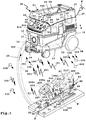
- a suction device 10 has a suction cup 11.
- the nipple housing 11 comprises a lower part 12 and an upper part 13, which is releasably connectable to the lower part 12.
- rollers 14 are arranged, of which the in FIG. 1 front castors are 14 castors.
- a dust collecting space 15 is provided, for example, a receptacle.
- a filter bag can be arranged in the dust collection chamber 15, for example, a filter bag can be arranged.
- the suction device 10 can also be used without a filter bag.
- the dust collecting space 15 is provided in the lower part 12.
- On a front wall 16 of the sucker housing 11, a suction inlet 17 is provided, to which a suction hose 18 can be connected.
- the suction inlet 17 opens into the dust collecting space 15.
- the electrical components of the suction device 10 are housed protected in the nipple housing 11.
- the electrical components in the upper part 13 are arranged, for example, a suction motor 19, with which a suction flow 20 can be generated.
- the suction motor 19 includes, for example, an unspecified explained the fan assembly for generating the suction flow 20th
- the suction device 10 can be operated in a manner known per se, for example via control elements 21, which are arranged on a control wall 22 provided above the front wall 16. There are, for example, a main switch 23 for switching on or off the suction motor 19 or a setting switch 24 for setting a suction power of the suction device 10th
- a socket 25 is still provided, in which a power cord of an electrical load, for example, a hand-held machine tool, not shown, can be inserted.
- the suction device 10 can be supplied with electrical energy via a schematically represented internal energy storage 26, for example a fuel cell or an electric accumulator, and / or connected to an electrical power supply system N, for example 110 V to 230 V AC, for which a connection cable 27 is provided is.
- the connection cable 27 and the suction hose 18 can be inserted when not in use in a receptacle 28 on an upper side 29 of the sucker housing 11.
- the suction hose 18 has a housing end 30 which is configured as a plug-in end and can be plugged into or into the suction inlet 17 in a manner known per se. Its other end forms a suction end 31 and has a suction opening 32, with which, for example, a rigid suction tube, a brush or the like is connectable or what in FIG. 1
- a hand-held machine tool 80 is, for example, a jigsaw, although other saws, for example a circular saw, or milling or the like are alternatively possible.
- the hand-held power tool 80 is an electric machine, that is, it has an electric drive motor 81, but with respect to the later still leadless control concept and / or reporting concept, other drive concepts of a hand-held machine tool with, for example, a pneumatic motor in connection with a particular Polishing tool or grinding tool are readily possible.
- the drive motor 81 drives a tool 82, for example a saw blade, with which a workpiece W can be processed.
- a tool 82 for example a saw blade
- the hand machine tool 80 is used to cut a saw cut S into the workpiece W. This creates dust that is sucked by the suction device 10.
- the drive motor 81 is disposed in a machine housing 83 of the hand machine tool 80.
- a holder 84 for holding the energy storage module 90 hidden by an energy storage module 90 in the drawing, the holder 84 also having electrical contacts 85 (indicated schematically) for electrically connecting the energy storage module 90 to the electrical components inside of the machine housing 83 are located.
- the energy storage module 90 supplies the manual power tool 80 with electrical energy, so that it can be operated freely without connection to an electrical power supply network, for example the power supply network N.
- the hand-held power tool 80 has a dust suction port 86, for example, a connecting piece, which is connectable to the suction end 31 of the suction hose 18.
- a dust suction port 86 for example, a connecting piece, which is connectable to the suction end 31 of the suction hose 18.
- the suction device 10 can be switched by means of a wire-free operating concept without a line connection, so that, for example, the suction motor 19 runs or does not run when the manual machine tool 80 is used or not.
- the suction device 10 enables a comfortable charging of the energy storage module 90.
- an external communication device 50 is arranged at the suction end 31 of the suction hose 18, with the wireless control signals 51 for controlling the suction device 10, in particular for switching on and off of the suction motor 19, can be generated.
- the external communication device 50 is attached to the suction hose 18, for example by means of a Velcro tape or other fastening means 52. It would also be possible for the suction hose 18 to have a pocket or other receptacle in which the external communication device 50 is arranged. It is also possible for the external communication device 50 to be encapsulated with the material, for example plastic, of the suction hose 18.
- the external communication device 50 includes, for example, a motion sensor 53, which responds to movements of the suction hose 18.
- a motion sensor 53 which responds to movements of the suction hose 18.
- the motion sensor 53 generates a sensor signal 54.
- the sensor signal 54 Based on the sensor signal 54 generates an external transmitter 55s the control signal 51, in this case a radio signal, the the external communication device 50 via an antenna 56 shipped.
- the external communication device 50 expediently has a local energy store 57, for example a battery and / or a storage capacitor, and / or a generator 58 for generating electrical energy.
- the generator 58 may for example be a generator which can be charged by means of a particular inductively operating charging device 33 which is arranged on or in the sucker housing 11, without wires, which is indicated by an arrow PL.
- the generator 58 can also be actuated, for example, by movements be. In any case, it is preferable if no line connection is necessary between the nipple housing 11 and the external communication device 50, wherein, for example, a line connection to the electrical power supply is also possible in principle.
- electrical charging contacts 133 may be provided for charging an external communication device according to the invention.
- the charging device 33 and the charging contacts 133 form charging means 233.
- a schematically illustrated charging bay or charging receptacle 355 with the charging contacts 133 and / or the charging device 33 is provided on the upper side 29 of the sucker housing 11.
- the suction device 10 has an electric suction device communication device 40 with a suction device receiver 41 r for receiving the control signals 51 sent by the external communication device 50.
- the suction device communication device 40 comprises, for example, a suction device communication module 42, which is accommodated in a module receptacle 34 on the suction cup housing 11.
- the sucker receiver 41r receives the control signals 51, e.g. via an antenna 46.
- the antenna 46 may e.g. protrude in front of a housing of the suction device communication module 42, be integrated into this or the like.
- the module receptacle 34 has, for example, a plug-in receptacle 35, into which a plug-in projection 43 described in more detail in connection with a charging module 60 can be plugged.
- electric module contacts 44 which can come into electrical connection with module contacts 36 of the module receptacle 34, are provided on the plug-in projection 43.
- the module contacts 44 are, for example, on a preferably in shape a plug-in projection designed contact carrier 45 is provided which is provided for insertion into a plug-in receptacle 39 of the module receptacle 34.
- the module contacts 36, 44 are expediently proprietary contacts, that is not about protective contacts as it has, for example, arranged on the connecting cable 27 plug.
- the module contacts 36, 44 which for the transmission of electrical energy and / or for the transmission of control signals and / or alarm signals.
- the module receptacle 34 has, for example, a substantially rectangular cross-sectional contour and is designed as a recess.
- the suction device communication module 42 sends, for example via its module contacts 44, switching signals 47 to a control device 37, which in turn controls the suction motor 19, e.g. via suitable circuit breakers, semiconductors or the like.
- a control device 37 which in turn controls the suction motor 19, e.g. via suitable circuit breakers, semiconductors or the like.
- the suction device communication module 42 controls the control device 37 accordingly, which in turn turns on, off or also the suction motor 19 Adjustment of power, for example, the speed is reduced or increased, which is indicated by an arrow 48.
- a variant of the invention can provide that the control device of a suction device integrally has a line-less interface, so that a separate suction device communication module, such as the suction device communication module 42, is not necessary.
- the suction device receiver 41r could form part of the control device 37.
- suction device communication device 40 e.g. forms an integral part of the suction device 10.
- the sucker communication device 40 may be e.g. form a part of the control device 37.
- a wireless interface could also be provided between the suction device communication device 40 and the control device 37.
- a potential-free coupling between the suction device communication device 40 and the other electrical components of the suction device 10 is preferred, which can be achieved, for example, by means of optocouplers.
- an external communication device 150 is disposed on board the handheld machine tool 80, or an external communication device 250 is disposed on board the energy storage module 90 and can communicate with the suction device communication device 40 without a lead.
- the external communication devices 150 and 250 may be integral components of the energy storage module 90 and the handheld machine tool 80, respectively. However, it is also a modular concept possible, that is, for example, on the hand-held machine tool 80 and / or the energy storage module 90, a module recording is present, in which the corresponding modular, designed for example as plug-in external communication devices 150 or 250 can be arranged. Furthermore, the external communication devices 150 and / or 250 can also be subsequently arranged on the energy storage module 90 or the handheld machine tool 80 by means of fastening means, for example adhesives, latching connection means or the like. Thus, a retrofit is possible.
- the external communication device 150 includes, for example, a rotational speed sensor 153, which detects a respective rotational speed of the drive motor 81.
- the speed sensor 153 controls an external transmitter 155s including, for example, a Bluetooth transmitter for transmitting control signals 151 through an antenna 156 integrated into the machine housing 83, for example is on, whereupon the suction device communication device 40 turns on the suction motor 19 or sends a switch-on signal to the control device 37.
- the external communication device 150 can control the suction device communication device 40 to an increased speed of the suction motor 19.
- the hand machine tool 80 is turned off, the external communication device 150 controls to turn off the suction motor 19.
- a magnetic sensor instead of or in addition to the rotational speed sensor 153, for example, a magnetic sensor, a Hall sensor or the like could be provided.
- a current sensor can also be provided onboard the hand-held machine tool 80, which detects the current flow to the drive motor 81 or a working-field illumination, not shown, of the hand-held machine tool 80, which illuminates during operation, and the external communication device 150 accordingly a control signal 151 generates to drive the suction device communication device 40.
- a voltage sensor may also be provided which measures a supply voltage applied to the drive motor 81 or the working field illumination.
- a schematically indicated embodiment provides that, for example, a position sensor and / or a magnetic sensor and / or an electrical switching contact or the like of another sensor 153 'are arranged on a switch 87 which serves for switching on and off the drive motor 81 of the hand-held machine tool 80 is that detects the position of the switch 87 or actuated in dependence on its position, so that the external communication device 150 in response to a position of the switch 87 generates the control signals 51 and thus the suction motor 19 by means of the suction device communication device 40 turns on and / or turns off and / or stops its performance.
- an external communication device can of course also have a plurality of sensors, switching contacts and the like, so that it generates the control signal as a function of at least two sensor signals or signals from switching contacts.
- the external communication device 150 evaluates the sensor signals of the sensors 153 and 153 'and only transmits the control signal 51 for turning on the suction motor 19 when both sensors 153 and 153' indicate that the drive motor 81 of the hand machine tool 80 is running.
- the suction device 10 is still running after a fixed or preferably parameterizable overrun time, ie the suction motor 19 only after a certain time, if the Hand machine tool 80 is already switched off, is also switched off.
- the suction motor 19 is still running after a fixed or preferably parameterizable overrun time, ie the suction motor 19 only after a certain time, if the Hand machine tool 80 is already switched off, is also switched off.
- a switch-on delay time is permanently set or parameterized, so that it turns on the suction motor 19 only after the switch-on delay time, if they by the control signal 51 for switching on the suction motor 19th has been controlled.
- the external communication device 250 forms a component of the energy storage module 90 and comprises a current sensor 253 which comprises a current flow from the energy storage module 90 to the manual power tool 80, in particular its drive motor 81.
- a current sensor 253 detects a current flow
- an external transmitter 255s generates a corresponding control signal 251 for driving the suction device communication device 40 to turn on the suction motor 19.
- the external communication device 250 sends a corresponding shutoff control signal 251, whereupon the suction device communication device 40 turns off the suction motor 19.
- the external communication device 250 is arranged in an energy storage housing of the energy storage module 90.
- an intermediate module Provide 100 which is connected between terminals 92 of the energy storage module 90 and the contacts 85 of the hand-held machine tool 80 to detect the flow of current from the energy storage module 90 to the hand machine tool 80 and the drive motor 81 and to generate a corresponding control signal 251.
- the intermediate module 100 is indicated.
- a preferred embodiment provides that a suction device communication device and an external communication device, which communicate with each other without line, in the context of a learning process, e.g. a so-called teach function, so to speak, get to know each other.
- a misuse or a misuse can be prevented.
- the external communication device 50 first sends a communication identifier 59 to the suction device receiver 41r, which in turn checks, for example, using a comparison list, if the communication identifier 59 authorizes the external communication device 50 to transmit the control signals 51.
- suction devices for example, if several craftsmen work on a construction site and turn on and off with their hand tools according to the invention suction devices and thus can be prevented that it comes to interference.
- the suction device communication device 40 prefferably be ready to receive the communication identifier 59, for example by pressing an electrical contact of the suction device communication device, not shown in the drawing, thus thus the external communication device 50, 150, 250 as an authorized external Communication recognizes and then from her then the control signals 51, 151, 251 accepted.
- the charging module 60 can also have or form a suction device communication device according to the invention, for example a suction device communication device 140.
- the external communication device 150 may send a malfunction of the handheld machine tool 80 in the frame by means of an external transmitter 155s as a notification signal 101 to the suction device communication device 40, which in turn then receives the notification signal 101 via a suction device receiver 41r and, for example, one optical display 102, for example an LED, to display the message signal 101 drives.
- the external communication device 250 which is for example on board the energy storage module 90
- the charging module 60 which includes the suction device communication device 140
- a wireless communication is appropriate.
- the external communication device 250 by means of an external transmitter 255s to the charging module 60, so the charging device 61, by means of a message signal 201 to report the state of charge of the energy storage module 90.
- the sucker communication device 140 receives the notification signal via a sucker receiver 141r.
- an optical and / or acoustic display 103 on board the charging device 61 be provided, which indicates the state of charge of the external, operated on the hand-held machine tool 80 energy storage module 90.
- the external communication device 250 includes, for example, a measuring device 257 for detecting the state of charge of the energy storage module 90 and for generating the reporting state of the reporting signal 201.
- the aforementioned wireless concept is also applicable in the reverse direction, that is, the suction device communication devices 40, 140 send messages or signals to the external communication devices 50, 150, 250.
- suction device transmitters 41 s and 141 s are provided, which are designed to send control signals and / or signaling signals to the external communication devices 50, 150, 250.
- the suction device transmitter 41s can a reporting signal 105 to the External communication device 50 send, which on optical or acoustic output means 106, which include, for example, an LED outputs the contents of the message signal 105.
- the operator can recognize on the basis of this on-site, in the hand-held machine tool 80 signal output that he has to empty, for example, the sump of the suction device 10.
- the control device 37 can therefore generate an alarm signal 105 or a message by means of the suction device communication device 40, which sends it via the suction device transmitter 41s to one or more of the external communication devices 50, 150 or 250.
- the message signal 105 which as indicated may also be a complex message containing a plurality of information or may also comprise a plurality of separate messages, contains, for example, information about the size of the suction flow 20 and / or a suction power of the suction motor 19 and / or information about a level of the dust collecting space 15th
- the external communication devices 50, 150 or 250 may output one or more information of the signaling signal 105, for example to output means 106, which comprise, for example, a light display, for example LEDs, and / or a display and / or a loudspeaker or other acoustic output means. If, for example, the message signal 105 signals that soon the dust collecting space 15 and / or a filter arranged therein, not shown in the drawing, is completely filled and dirty, for example a display LED configured as a warning LED 107 of the external communication device 50 can display this ,
- the external communication device 150 or 250 disposed onboard the energy storage module 90 or the intermediate module 100 or the handheld machine tool 80 may, for example, be Also include a haptic display, a vibration display or the like to output the message signal 105.
- a haptic display, a vibration display or the like to output the message signal 105.
- an optical and / or acoustic display 104 and / or a vibration element 109 may be provided as an output means on board the handheld machine tool 80, which at a critical level in the dust collection space 15 and / or at a lower suction power of the suction device 10, which in Signaling signal 105 is signaled vibrates and the operator indicates that he should take care of the suction device 10, so that the desired suction power is available.
- suction device 10 and / or the suction device communication devices 40 or 140 directly influence the function of the handheld machine tool 80 by means of a control signal 108.
- the control device 37 can send information 147 to the suction device communication devices 40 or 140, which generates the control signal 108 corresponding thereto and to the external communication devices 50.
- 150, 250 sends.
- the external communication devices 150 or 250 may then directly affect the operation of the handheld machine tool 80.
- the control signal 108 may instruct to reduce the power of the drive motor 81 or even turn it off completely. As a result, it can be avoided, for example, that the user takes damage to health from swirling particles when the suction device 10 can no longer adequately remove the particles produced by the hand-held machine tool 80.
- the external communications device 250 located onboard the energy storage module 90 may turn off and on the power flow to the handheld machine tool 80 by means of a switching device 258, e.g. after activation by the control signal 108.
- the external communication device 250 may be e.g. a wired or preferably wireless interface 259, e.g. a radio interface for communicating with the handheld machine tool 80, in particular its controller 88, e.g. to forward the control signal 108 and / or to communicate the operating parameters 450, 400 and / or the identifiers 410, 460.
- a wired interface 259 may be e.g. Provide that data on the supply lines to the handheld machine tool 80 digitally transmitted and / or modulated.
- the external communication device 150 is directly connected to the controller, for example, an on-board electronics, the hand-held machine tool 80 or forms part of it, so that this can directly influence the operation of the drive motor 81 in this way, so it can turn off, for example ,
- the controller for example, an on-board electronics, the hand-held machine tool 80 or forms part of it.
- the suction device communication devices 40, 140 and / or the external communication devices 50, 150, 250 have, for example, a microprocessor and / or are suitable for the execution of software modules with which the functions explained above or explained below can be implemented.
- the external communication device 50 has a microprocessor 70, which by means of a program module 71 evaluates the sensor signals 54 and controls or realizes, for example, the external transmitter 55s and / or the external receiver 55r.
- the program module 71 like the communication identifier 59, is expediently stored in a memory 72.
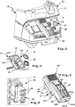
- the charging module 60 is for charging the energy storage module 90 or other energy storage modules, not shown in the drawing, for hand machine tools, such as the hand machine tool 80 or one in FIG FIG. 8 shown hand-tool 180 in the form of a cordless screwdriver or drill provided.
- the charging module 60 forms a charging device 61 for charging the electrical energy storage module 90.
- the charging module 60 has on its charger housing 62 a holder 63 for holding the energy storage module 90.
- the holder 63 includes, for example, a plug-in projection 64, which can be inserted into a plug-in receptacle 93 of the energy storage housing 91 or the energy storage module 90.
- the holder 63 also includes a plug receptacle or holding receptacle 68 into which a plug projection 94 on an upper side 95 of the energy storage housing 91 can engage.
- the bracket 63 corresponds to the bracket 84 of the handheld machine tool 80 or 180, i. it is designed for positive reception of the energy storage housing 91.
- electrical charging contacts 65 are provided for providing a charging voltage L for the electrical energy storage module 90.
- the charging voltage L is for example a DC voltage in a range of 5 V to 25 V.
- the charging module 60 detection means 66 to detect the respective type of the energy storage module 90 and accordingly set the charging voltage L. If, for example, a 12 V energy storage module is connected, the charging voltage L is set correspondingly lower, while in the case of an energy storage module with a nominal voltage of 18 V, a correspondingly higher charging voltage L is inserted.
- the detection means 66 include, for example, electrical means, optical means, or the like. It is also possible for the detection means 66 to include, for example, a bus interface in order to communicate with a bus coupler on board the energy storage module 90 and thus to acquire data of the energy storage module 90, for example its charge state, nominal voltage or the like.
- the charging device 61 can convert a supply voltage V provided, for example, from the supply network N to the charging voltage L.
- monitoring means 75 are advantageously provided for monitoring the charging voltage L and / or for monitoring a charging state of the energy storage module 90, so that it is optimally charged.
- the monitoring means 75 and / or detection means 66 and / or the adaptation means 67 comprise, for example, a microprocessor 76 which executes program code of software modules, for example a software module 78 stored in a memory 77.
- a microprocessor 76 which executes program code of software modules, for example a software module 78 stored in a memory 77.
- a realization of the monitoring means 75 and / or the detection means 66 and / or the adaptation means 67 in hardware is readily possible.
- the charger housing 62 is partially configured similar to the suction device communication module 42, thus also has a plug projection 43, are provided on the module contacts 44 for establishing an electrical connection with the module contacts 36 of the module receptacle 34.
- the adjustment means 67 disposed inside the charger housing 62 may be removed from the aspirator 10, i. for example, via the connecting cable 27, are supplied with electrical energy to provide the charging voltage L.
- An additional fixation of the loading module 60 on the sucker housing 11 or the module receptacle 34 can be effected for example by means of screws 69, which can be screwed into corresponding screw openings 38 of the module receptacle 34.
- a magnetic stop, latching or the like of the loading module 60 on the sucker housing 11 is readily possible, but not shown in the drawing.
- the suction device communication module 42 can expediently also have corresponding holding means (screws, magnets, latching means) in order to find a secure hold in the module receptacle 34.
- the charging module 60 and the charging device 61 forms an integral part of the suction device 10, that is, for example, the charger housing 62 and the nipple housing 11 are integral.
- a holder in the manner of the holder 63 and charging contacts in the manner of the charging contacts 65 may be arranged at another point of the sucker housing 11, for example, above in the region of the receptacle 28, where to be loaded Energy storage module can be accommodated protected, that is less exposed than in the area of the control wall 22nd
- the suction device communication device 140 formed by the loading module 60 has, for example, a suction device receiver 141r. Via the module contacts 36, the charging module 60 is supplied with electrical energy, for example a supply voltage V. A current sensor 49 on board the suction device 10, for example as part of or in conjunction with the control device 37, detects, for example, whether an electrical current flows via the module contacts 36.
- the charging module 60 When the charging module 60 receives a control signal 51, 151, 251 for switching on the suction motor 19 via its suction device receiver 141r and an antenna 146 integrated, for example, in the charger housing 62, it begins charging the energy storage module 90, ie it generates the supply voltage V Charging voltage L, so that a charging current I flows. An input current E necessary for providing the charging current I is detected by the current sensor 49.
- the suction device 10 thus recognizes that an electrical load requires power and then turns on the naturally aspirated motor 19 in a manner known per se.
- the suction device communication device 140 or the charging module 60 reduces the power supply to the energy storage module 90 or switches off the charging process, so that the input side (supply voltage V) no input current E detectable by the current sensor 49 or an input current E lying below a detection threshold flows, and thus, for example, the control device 37 shuts off the suction motor 19.
- the charging module 60 can virtually simulate a network-connected electric hand-held machine tool, which via the suction device 10 with electrical energy is supplied - which is actually not the case.
- the charging device 61 is supplied by the energy storage 26 on board the suction device 10 with electrical energy.
- the control device 37 controls the provision of electrical energy to the module contacts 36. It is preferably provided that the control device 37, for example, the power output at the module contacts 36 lowers when the suction motor 19 is running, then raises again. Thus, for example, a power supply of the suction device 10, which provides the charging voltage L, less heavily loaded.
- the suction device communication devices 40 and / or 140 and the external communication devices 50, 150, 250 located on or connected to the suction device 10 are also suitable for a log-on procedure in which the suction device 10 has at least one operating parameter 400 and / or at least one Identification code 410 sends to the external device, for example the handheld machine tool 80 and / or its energy storage module 90 and / or in the reverse direction the device to be connected to the suction device 10, for example the handheld machine tool 80 or its energy storage module 90 at least one operating parameter 450 and / or or at least one identifier 460 sends to the suction device 10, so that only matching pairs of suction device and hand machine tool are used and / or the operating parameters of the suction device 10 and the hand-held machine tool 80 or 180 are set so that an optimal operation of respective hand-who Machine 80 or 180 on the suction device 10 is possible.
- the suction device 10 has at least one operating parameter 400 and / or at least one Identification code 410 sends to the external device, for example the handheld machine tool 80 and
- the suction power of the suction device 10 is insufficient for the operation of the manual power tool, it can be prevented from using the suction device 10 in conjunction with the manual power tool 80 by the procedure described in detail below.
- the suction power is sufficient for, for example, the hand machine tool 180, the suction apparatus 10 and the hand machine tool 180 may be used together.
- suction device 10 and the respective connected hand-held machine tool 80 or 180 coordinate their respective performances to each other by the one device registers with the other device and / or vice versa.
- a wireless communication between the hand-held power tool 80 and 180 on the one hand and the suction device 10, in particular their suction device communication devices 40, 140 is appropriate, but does not preclude that in particular for the registration procedure or identification procedure described below, but also the transmission of message signals and / or control signals, a wired communication, at least in one direction (from the suction device to the hand-machine tool or vice versa) within the scope of the invention.
- a wired communication at least in one direction (from the suction device to the hand-machine tool or vice versa) within the scope of the invention.
- in one direction that is, for example, from the suction device to the hand-held machine tool cable bound to be communicated in the reverse direction without wires or vice versa.
- At least one communication line 300 for example, an electrical line and / or an optical conductor
- the suction device communication devices 40 and / or the control device 37 or a Other component is connected on board the suction device 10 to communicate with the hand-held power tool 80 or 180.
- the external communication device 150 or 250 may be connected to the at least one communication line 300.
- the external communication device 150 or 250 sends the identification tag 460 identifying the handheld machine tool 80 to the suction device 10.
- the suction device communication device 40 receives the identification code 460 and forwards it, for example, to the control device 37, which recognizes, for example, the type of the hand-held machine tool 80, for example, what amount of particles is to be expected from this hand-held machine tool 80, which suction power corresponding to the identification code 460 is to be provided by the suction device 10 or the like.
- the control device 37 accordingly sets the function of the suction device 10, for example, such that the suction power of the suction motor 19 is adjustable on the adjusting switch 24, but not below a limit value which allows reliable extraction of the particles generated by the hand-held machine tool 80 ,
- the control device 37 may check whether an operation of the hand-held machine tool 80 with the suction device 10 is even possible if at least one criterion is met. If, for example, it should be noted that the suction device 10 should provide explosion protection in connection with the respective hand-held machine tool and / or at least one predetermined suction power of the suction device 10 is required, so that the at least one criterion is met, the controller 37 may determine whether the identification tag 460 is indicated in a table 430 containing a plurality of identification tags. If so, the controller 37 releases the suction device 10 for operation with the hand machine tool 80.
- the nature of the particles may also be different, including, for example, larger chips or smaller chips. Accordingly, it is expedient for the handheld machine tool 80, for example as an operating parameter 450, to send information about the tool 82 used to the suction device communication devices 40 or 140.
- the control device 37 can, for example, set cleaning intervals of a cleaning device 9 which cleans a filter 8, which precedes the suction motor 19.
- the suction device 10 logs on, so to speak, before the start of an operation.
- the suction device communication device 40 sends an identification code 410 of the suction device 10 and / or at least one operating parameter 400 to the manual machine tool 80.
- a controller 88 on-board the handheld machine tool 80 checks, based on a check table, whether the identification tag 410 classifies the suction device 10 so that it can be used in conjunction with the handheld machine tool 80. Only then does the controller 88 release the drive motor 81. Otherwise blocks the controller 88, the drive motor 81, so that, for example, health impairments User of the hand-held machine tool 80 can be avoided by not sucked particles.
- the suction device 10 can inform the hand-held machine tool 80, for example, which suction power can be available.
- the hand-held power tool 80 then reduces, for example, a maximum speed of the drive motor 81, so that even with a maximum switch 87 adjustable speed of the drive motor 81, the suction of the suction device 10 is sufficient to reliably all accumulating particles or at least substantially all particles from the working area of the hand Vacuum machine 80.
- the external communication devices 150 or 250 and / or the suction device communication devices 40 or 140 based on the respectively received identification code when the 410, 460 and / or the received operating parameters 400, 450 directly generate control signals and / or alarm signals and to the other Send communication equipment.
- the external communication devices 150 and / or 250 can determine from the identification code 410, for example, that the suction device 10 has to provide a specific output and accordingly sends a control signal 351 that controls the suction device 10 instructed to set a particular power level as a minimum adjustable power level on the control switch 24.
- a control signal 351 that controls the suction device 10 instructed to set a particular power level as a minimum adjustable power level on the control switch 24.
- the control signal 351 and a message signal 352 are generated, which is displayed for example by the display 102.
- the suction device 10 or the suction device communication devices 40, 140 can also be designed in this way.
- the suction device communication devices 40, 140 and / or the suction device 10 for example the control device 37, use the identification code 460 or the operating parameter 450 to determine which rotational speeds of the drive motor 81 of the handheld machine tool 80 are adjustable or adjustable and accordingly sends a control signal 353 and / or a report signal 354 to the external communication devices 150 or 250.
- the control signal 353 instructs them to communicate, for example, to the control device 88, which outputs of the drive motor 81 are to be adjustable at the switch 87.
- the information of the notification signal 354 is displayed on the display 104, for example, so that the operator knows which power ranges to be set on the hand machine tool 80 and / or which tools are usable or the like.
Landscapes
- Engineering & Computer Science (AREA)
- Mechanical Engineering (AREA)
- Auxiliary Devices For Machine Tools (AREA)
- Electric Vacuum Cleaner (AREA)
Abstract
Die Erfindung betrifft ein Verfahren zum Betreiben einer Hand-Werkzeugmaschine (80) mit einem Sauggerät (10), das einen Saugmotor (19) zum Erzeugen des Saugstroms (20) und ein Saugergehäuse (11), in dem der Saugmotor (19) und ein Staubsammelraum (15) zum Sammeln der aus dem Saugstrom (20) abgesonderten Partikel angeordnet ist, aufweist, wobei das Sauggerät (10) zum Absaugen von beim Betrieb einer einen Antriebsmotor (81) zum Antreiben eines Werkzeugs (82) aufweisenden Hand-Werkzeugmaschine (80), vorgesehen ist. Es ist vorgesehen, dass eine Sauggerät-Kommunikationseinrichtung (40; 140) des Sauggeräts (10) mit einer in einem Abstand zu dem Saugergehäuse (11) im Zusammenhang mit der Hand-Werkzeugmaschine (80) zu betreibenden oder einen Bestandteil der Hand-Werkzeugmaschine (80) bildenden Extern-Kommunikationseinrichtung (50; 150; 250) kommuniziert, wobei die Sauggerät-Kommunikationseinrichtung (40; 140) mindestens eine Identifikationskennung (410, 460) und/oder einen Betriebsparameter (400, 450) an die Extern- Kommunikationseinrichtung (50; 150; 250) sendet und/oder mindestens eine Identifikationskennung (410, 460) und/oder einen Betriebsparameter (400, 450) von der Extern-Kommunikationseinrichtung (50; 150; 250) empfängt, und dass das Sauggerät (10) und/oder die Hand-Werkzeugmaschine (80) mindestens eine Funktion anhand der jeweils empfangenen mindestens einen Identifikationskennung (410, 460) und/oder des jeweils empfangenen Betriebsparameters (400, 450) ausführen.The invention relates to a method for operating a hand-held machine tool (80) with a suction device (10) having a suction motor (19) for generating the suction flow (20) and a suction housing (11) in which the suction motor (19) and a Dust collecting chamber (15) for collecting the separated from the suction flow (20) particles is arranged, wherein the suction device (10) for sucking in the operation of a drive motor (81) for driving a tool (82) having hand-held machine tool (80 ), is provided. It is provided that a suction device communication device (40; 140) of the suction device (10) with a distance to the nipple housing (11) in connection with the hand-held machine tool (80) or a part of the hand-held machine tool ( 80) communicates, wherein the suction device communication device (40; 140) at least one identification code (410, 460) and / or an operating parameter (400, 450) to the external communication device (50 150, 250) and / or receives at least one identification code (410, 460) and / or operating parameter (400, 450) from the external communication device (50; 150; 250), and that the suction device (10) and / or or the hand-held power tool (80) perform at least one function based on the respectively received at least one identification code (410, 460) and / or the respectively received operating parameter (400, 450).
Description
Die Erfindung betrifft ein Verfahren zum Betreiben einer Hand-Werkzeugmaschine mit einem Sauggerät, das einen Saugmotor zum Erzeugen des Saugstroms und ein Saugergehäuse, in dem der Saugmotor und ein Staubsammelraum zum Sammeln der aus dem Saugstrom abgesonderten Partikel angeordnet ist, aufweist, wobei das Sauggerät zum Absaugen von beim Betrieb einer einen Antriebsmotor zum Antreiben eines Werkzeugs aufweisenden Hand-Werkzeugmaschine, vorgesehen ist. Die Erfindung betrifft ferner eine insbesondere einen Bestandteil der Hand-Werkzeugmaschine bildende Extern-Kommunikationseinrichtung und ein Sauggerät.The invention relates to a method for operating a hand-held power tool with a suction device, which comprises a suction motor for generating the suction flow and a suction housing, in which the suction motor and a dust collecting space for collecting the separated from the suction flow particles is arranged, wherein the suction device for Sucking off during operation of a hand tool machine having a drive motor for driving a tool, is provided. The invention further relates to a particular part of the hand-machine tool forming external communication device and a suction device.
Ein derartiges Sauggerät ist beispielsweise aus
Es ist die Aufgabe der vorliegenden Erfindung, die Nutzbarkeit eines Sauggerätes zu verbessern.It is the object of the present invention to improve the usability of a suction device.
Zur Lösung der Aufgabe ist bei einem Verfahren der eingangs genannten Art vorgesehen, dass eine Sauggerät-Kommunikationseinrichtung des Sauggeräts mit einer in einem Abstand zu dem Saugergehäuse im Zusammenhang mit der Hand-Werkzeugmaschine zu betreibenden oder einen Bestandteil der Hand-Werkzeugmaschine bildenden Extern-Kommunikationseinrichtung kommuniziert, wobei die Sauggerät-Kommunikationseinrichtung mindestens eine Identifikationskennung und/oder einen Betriebsparameter an die Extern-Kommunikationseinrichtung sendet und/oder mindestens eine Identifikationskennung und/oder einen Betriebsparameter von der Extern-Kommunikationseinrichtung empfängt, und dass das Sauggerät und/oder die Hand-Werkzeugmaschine mindestens eine Funktion anhand der jeweils empfangenen mindestens einen Identifikationskennung und/oder des jeweils empfangenen Betriebsparameters ausführen.To solve the problem is provided in a method of the type mentioned that a suction device communication device the suction device communicates with an external communication device to be operated at a distance from the vacuum cleaner housing in conjunction with the hand-held machine tool or forming part of the hand-held machine tool, wherein the suction device communication device transmits at least one identification identifier and / or an operating parameter to the external communication device sends and / or receives at least one identification identifier and / or an operating parameter from the external communication device, and that the suction device and / or the hand-held machine tool perform at least one function based on the respectively received at least one identification identifier and / or the respectively received operating parameter.
Die Erfindung betrifft ferner ein Sauggerät, das mit einer Sauggerät-Kommunikationseinrichtung ausgestattet ist oder mit dieser direkt kommuniziert sowie eine Extern-Kommunikationseinrichtung, insbesondere als Bestandteil einer Hand-Werkzeugmaschine.The invention further relates to a suction device which is equipped with a suction device communication device or communicates directly with it and an external communication device, in particular as part of a hand-held machine tool.
Es ist ein Grundgedanke der vorliegenden Erfindung, dass sich die Hand-Werkzeugmaschine bei dem Sauggerät anmeldet und/oder umgekehrt und in diesem Zusammenhang eine Identifikationskennung und/oder eine Betriebsparameter an das jeweils andere Gerät sendet. Anhand dieser Informationen ist eine Initialisierung möglich derart, dass beispielsweise das Sauggerät anschließend seinen Betriebsmodus so einstellt, dass dieser zu der Hand-Werkzeugmaschine passt. Wenn also beispielsweise das Werkzeug eine Hand-Säge ist, die eine große Menge von Partikeln beim Sägen in ein Werkstück produziert, stellt der Sauger entsprechend höhere Saugleistung ein. Auch die Abreinigung eines Filters des Sauggeräts kann dann entsprechend häufiger erfolgen, d.h. dass ein Abreinigungsintervall beispielsweise bei einer Kreissäge wesentlich kleiner ist als beispielsweise bei einer Stichsäge, die weniger Partikel bei ihrem Betrieb erzeugt. An dieser Stelle sei bemerkt, dass die Hand-Werkzeugmaschine selbstverständlich unterschiedlich ausgestaltet sein kann, beispielsweise eine Bohrmaschine, eine Säge, insbesondere eine Kreissäge, Tauchsäge oder dergleichen umfassen kann.It is a basic idea of the present invention that the hand-held machine tool registers with the suction device and / or conversely and in this context sends an identification code and / or an operating parameter to the respective other device. Based on this information, an initialization is possible such that, for example, the suction device then adjusts its operating mode so that it fits the hand-held machine tool. So, for example, if the tool is a hand saw that produces a large amount of particles when sawing into a workpiece, the sucker will set a correspondingly higher suction power. The cleaning of a filter of the suction device can then be done correspondingly more frequently, ie that a Abreinigungsintervall, for example, in a circular saw is much smaller than, for example, a Jig saw that generates fewer particles in its operation. It should be noted that the hand-held machine tool can of course be designed differently, for example, a drill, a saw, in particular a circular saw, dip saw or the like may include.
Es ist möglich, dass das einen Betriebsparameter oder eine Identifikationskennung empfangende Gerät, also das Sauggerät oder die Hand-Werkzeugmaschine, anhand der empfangenen Identifikationskennung bzw. des empfangenen Betriebsparameters seine spätere Funktionsweise einstellt, so dass beispielsweise das Sauggerät sich auf die Hand-Werkzeugmaschine einstellt und dementsprechend beispielsweise die Saugleistung nicht unter ein Mindestmaß sinken oder über ein Maximum ansteigen lässt. Wenn mit der Hand-Werkzeugmaschine, z.B. einer Schleif- oder Poliermaschine, beispielsweise entsprechend empfindliche Oberflächen zu bearbeiten sind, kann eine zu große Saugleistung hinderlich sein. Auf der anderen Seite kann eine zu geringe Saugleistung, ein verstopfter Filter oder dergleichen auf Seiten des Sauggeräts auch zu unerwünschter Beeinträchtigung der Umwelt führen, d.h. dass das Sauggerät nicht in ausreichendem Maße Partikel aus dem Arbeitsbereich der Hand-Werkzeugmaschine absaugt. Dies kann an sich zu gesundheitlichen Beeinträchtigungen des Nutzers führen. Die Erfindung kann hier Abhilfe schaffen, indem das Sauggerät quasi erkennt, welche Hand-Werkzeugmaschine angeschlossen ist und dementsprechend seine Betriebsparameter beziehungsweise Arbeitsparameter einstellt.It is possible for the device, which receives an operating parameter or an identification code, that is to say the suction device or the hand-held machine tool, to set its later functioning on the basis of the received identification code or the received operating parameter, so that, for example, the suction device adjusts to the hand-held machine tool and Accordingly, for example, the suction power can not fall below a minimum or above a maximum increase. If with the hand tool, e.g. a grinding or polishing machine, for example, correspondingly sensitive surfaces are to be processed, a too large suction power can be a hindrance. On the other hand, too low a suction power, a clogged filter or the like on the suction device side can also lead to undesirable environmental damage, i. that the suction device does not sufficiently suck particles from the working area of the hand-held machine tool. This can in itself lead to health problems of the user. The invention can remedy this situation by virtue of the fact that the suction device virtually recognizes which hand-held machine tool is connected and accordingly sets its operating parameters or working parameters.
Die im Zusammenhang mit dem erfindungsgemäßen Verfahren vorgeschlagenen Maßnahmen der abhängigen Ansprüche können sich selbstverständlich auch in entsprechende Ausgestaltung des Sauggeräts, der Sauggerät-Kommunikationseinrichtung und der Extern-Kommunikationseinrichtung niederschlagen. Beispielsweise haben diese Geräte zur Durchführung der jeweiligen Schritte geeignete Betriebsmittel, zum Beispiel einen Mikroprozessor und geeignete Programme oder dergleichen.Of course, the measures of the dependent claims proposed in connection with the method according to the invention can also be reflected in corresponding design of the suction device, the suction device communication device and the external communication device. For example, these devices have to carry out the respective steps suitable resources, for example a microprocessor and suitable programs or the like.
Nachfolgend werden einige erfindungsgemäße Schritte erläutert:
Eine vorteilhafte Maßnahme sieht vor, dass das Sauggerät oder die Hand-Werkzeugmaschine anhand des empfangenen Betriebsparameters und/oder der Identifikationskennung ermittelt, ob oder unter welchen Bedingungen ein mindestens einem Kriterium entsprechende Betrieb der Paarung bestehend aus Sauggerät und der Hand-Werkzeugmaschine möglich ist. Bei dem Kriterium kann es sich beispielsweise um ein Sicherheitskriterium, ein Umweltkriterium, ein Arbeitsschutz-Kriterium oder dergleichen handeln. Wenn also beispielsweise das Sauggerät nicht in ausreichendem Maße Partikel absaugen kann, ist es möglich, dass das Sauggerät und/oder Hand-Werkzeugmaschine einen späteren Betrieb blockiert. Der Benutzer wird dadurch geschützt.Some steps according to the invention are explained below:
An advantageous measure provides that the suction device or the hand-held machine tool based on the received operating parameter and / or identification identification determines whether or under what conditions an at least one criterion corresponding operation of the pairing consisting of suction device and the hand-held machine tool is possible. The criterion may be, for example, a safety criterion, an environmental criterion, a health and safety criterion or the like. If, for example, the suction device can not suck off particles to a sufficient extent, it is possible for the suction device and / or hand-held machine tool to block later operation. The user is protected by this.
Das Sauggerät und/oder die Hand-Werkzeugmaschine verfügen zweckmäßigerweise über ein Ausgabemittel oder mehrere Ausgabemittel, um beispielsweise mindestens einen Betriebsparameter und/oder mindestens eine Identifikationskennung und/oder das obige mindestens eine Kriterium auszugeben. An dem Ausgabemittel kann selbstverständlich auch vorteilhaft angegeben werden, ob und unter welchen Bedingungen der das mindestens eine Kriterium erfüllende Betrieb der Paarung bestehend aus Sauggerät und Hand-Werkzeugmaschine möglich ist. Der Bediener erhält also eine Rückkoppelung, welche Informationen ausgetauscht werden und/oder wie ein späterer Betrieb möglich ist. Wenn beispielsweise das Sauggerät und die Hand-Werkzeugmaschine zueinander passen, kann eine beispielsweise grüne Leuchtanzeige oder dergleichen als ein optisches Ausgabemittel aktiviert werden. Ein solches Ausgabemittel kann bei der Hand-Werkzeugmaschine und/oder bei dem Sauggerät, beispielsweise an der Sauggerät-Kommunikationseinrichtung und/oder bei der Extern-Kommunikationseinrichtung, vorgesehen sein.The suction device and / or the hand-held machine tool expediently have one or more output devices, for example to output at least one operating parameter and / or at least one identification code and / or the above at least one criterion. Of course, it can also advantageously be indicated at the output means whether and under what conditions the operation of the pairing comprising the suction device and the hand-held machine tool fulfilling the at least one criterion is possible. The operator thus receives a feedback, which information is exchanged and / or how a later operation is possible. For example, when the suction apparatus and the hand machine tool are matched, an example green light display or the like may be activated as an optical output means. Such an output means may be in the hand-held power tool and / or in the suction device, for example at the suction device communication device and / or at the external communication device, be provided.
Eine bevorzugte Ausführungsform der Erfindung sieht vor, dass das Sauggerät und/oder die Hand-Werkzeugmaschine so ausgestaltet sind, dass sie einen Betrieb mit dem jeweils anderen Gerät blockieren, wenn das mindestens eine Kriterium nicht erfüllbar ist. Wenn also beispielsweise das Sauggerät erkennt, dass die Hand-Werkzeugmaschine zu viele Partikel produzieren würde, die dann nicht absaugbar sind, kann das Sauggerät seinen Betrieb blockieren. Auch die Hand-Werkzeugmaschine kann einen Betrieb blockieren, wenn das Kriterium nicht erfüllbar ist oder nicht erfüllt ist.A preferred embodiment of the invention provides that the suction device and / or the hand-held power tool are configured such that they block operation with the respective other device if the at least one criterion can not be fulfilled. For example, if the suction device detects that the hand machine tool is producing too many particles that are not aspiratable then the suction device may block its operation. The hand-held machine tool can also block operation if the criterion can not be met or is not met.
Wenn der Betrieb von Sauggerät und Hand-Werkzeugmaschine zwar möglich ist, jedoch bestimmte Betriebs- oder Funktionsparameter dazu notwendig sind, damit ein optimaler Betrieb möglich ist, ist es vorteilhaft, wenn das Sauggerät und/oder die Hand-Werkzeugmaschine dazu ausgestaltet sind, einen oder mehrere Parameter für eine Funktion des Sauggeräts oder der Hand-Werkzeugmaschine entsprechend dem mindestens einen Kriterium einzustellen. Somit kann also beispielsweise das Sauggerät seine Saugleistung an die Hand-Werkzeugmaschine anpassen. Auch die Hand-Werkzeugmaschine ist vorteilhaft so ausgestaltet, dass sie beispielsweise nur in einem solchen Drehzahlbereich oder Arbeitsbereich benutzbar ist, dass das Sauggerät noch in der Lage ist, anfallende Partikel in einem dem Kriterium entsprechenden Umfang abzusaugen. Selbstverständlich kann auch ein Abreinigungsfunktion zur Abreinigung eines Filters des Sauggeräts anhand des Arbeitsparameters eingestellt werden, so dass das mindestens eine Kriterium erfüllt ist.Although the operation of the suction device and hand machine tool is possible, but certain operating or functional parameters are necessary for optimum operation to be possible, it is advantageous if the suction device and / or the hand-held power tool are configured to have one or more set several parameters for a function of the suction device or the hand-held machine tool according to the at least one criterion. Thus, for example, the suction device can adapt its suction power to the hand-held machine tool. The hand-held power tool is advantageously designed so that it is usable, for example, only in such a speed range or work area, that the suction device is still able to suck off particles accumulating in a corresponding extent to the criterion. Of course, a cleaning function for cleaning a filter of the suction device can be adjusted based on the working parameter, so that the at least one criterion is met.
An dieser Stelle sei bemerkt, dass eine Ausführungsform der Erfindung vorsieht, dass die Hand-Werkzeugmaschine anhand der vom Sauggerät erhaltenen Daten seine eigenen Betriebsparameter einstellt, d.h. beispielsweise einen Drehzahlbereich definiert, oder das Sauggerät anhand der von der Hand-Werkzeugmaschine erhaltenen Daten seine eigenen Betriebsparameter, beispielsweise Abreinigungsintervalle, Saugleistung und dergleichen, einstellt. Es ist aber auch möglich, dass das eine Gerät die Betriebsparameter des anderen Geräts modifiziert und/oder entsprechende Steuersignale sendet. Somit kann also beispielsweise das Sauggerät an die Hand-Werkzeugmaschine Betriebsparameter senden, die es der Hand-Werkzeugmaschine anhand der empfangenen Identifikationskennung der Hand-Werkzeugmaschine oder der empfangenen Betriebsparameter der Hand-Werkzeugmaschine vorgibt.It should be noted that an embodiment of the invention provides that the hand-held machine tool based on the data obtained by the suction device sets its own operating parameters, ie defines, for example, a speed range, or the suction device sets its own operating parameters, for example cleaning intervals, suction power and the like, based on the data obtained from the hand-held machine tool. But it is also possible that one device modifies the operating parameters of the other device and / or sends corresponding control signals. Thus, for example, the suction device can send operating parameters to the hand-held machine tool which it specifies for the hand-held machine tool based on the received identification code of the hand-held machine tool or the received operating parameters of the hand-held machine tool.
Die Identifikationskennung kann als eine solche Identifikationskennung ausgestaltet sein, dass sie das Sauggerät oder die Hand-Werkzeugmaschine jeweils eindeutig zu kennzeichnen, das aus der Identifikationskennung Betriebsdaten der Hand-Werkzeugmaschine bzw. Sauggeräts, zum Beispiel Leistungsdaten, Leistungsanforderungen oder dergleichen, ableitbar sind. Beispielsweise kann die Identifikationskennung den jeweiligen Typ des Sauggeräts oder Hand-Werkzeugmaschine angeben. Aber auch eine eindeutige, sozusagen weltweit nur einmal auftretende Kennung ist möglich. Selbstverständlich kann die Identifikationskennung auch mehrteilig sein, das so dass sie beispielsweise zum einen eine Typkennung des jeweiligen Geräts, zum andern auch eine eindeutige Serienkennung oder Seriennummer umfasst.The identification code can be configured as such an identification code that it can clearly identify the suction device or the hand-held machine tool that can be derived from the identification code for operating data of the hand-held machine tool or suction device, for example performance data, performance requirements or the like. For example, the identification code may indicate the respective type of suction device or hand-held machine tool. But even a unique, so to speak, only once occurring worldwide identifier is possible. Of course, the identifier can also be multi-part, so that it includes, for example, on the one hand a type identifier of the respective device, on the other hand, a unique serial identifier or serial number.
Bezüglich des mindestens einen Betriebsparameters ist es möglich, dass er beispielsweise ein Werkzeugmaschinen-Betriebsparameter der Hand-Werkzeugmaschine ist, der einen bei einem Betrieb der Hand-Werkzeugmaschine möglichen oder aktuellen Betriebszustand repräsentiert. Beispielsweise repräsentiert der Betriebsparameter eine beim Betrieb der Hand-Werkzeugmaschine typischerweise oder aktuell anfallende maximale Partikelmenge, eine typische Beschaffenheit der Partikel oder dergleichen.With regard to the at least one operating parameter, it is possible that it is, for example, a machine tool operating parameter of the hand-held machine tool which represents a possible or current operating state during operation of the hand-held power tool. For example, represented the operating parameters include a typical or current maximum amount of particulates occurring during operation of the hand-held power tool, a typical nature of the particles or the like.
Ein dem Sauggerät zugeordneter Betriebsparameter bildet zweckmäßigerweise einen Sauggerät-Betriebsparameter, der einen beim Betrieb des Sauggeräts aktuell oder möglicherweise auftretenden Betriebszustand repräsentiert. Der Sauggerät-Betriebsparameter oder die Sauggerät-Identifikationskennung können beispielsweise eine Saugleistung des Saugmotors und/oder eine maximale Größe des Saugstroms und/oder eine noch vorhandene Aufnahmekapazität für Partikel im Staubsammelraum oder in einem Filter innerhalb des Staubsammelraums angeben.An operating parameter assigned to the suction device expediently forms a suction device operating parameter which represents a current or possibly occurring operating state during operation of the suction device. The suction device operating parameter or the suction device identification code can indicate, for example, a suction power of the suction motor and / or a maximum size of the suction flow and / or a still present absorption capacity for particles in the dust collection space or in a filter within the dust collection space.
Das Sauggerät ist zweckmäßigerweise zur Einstellung mindestens einer Funktion des Sauggeräts und/oder der Hand-Werkzeugmaschine anhand der mindestens einen Identifikationskennung und/oder des Betriebsparameters ausgestaltet. Hierbei kann es sich um eine empfangene oder eine zu sendende Identifikationskennung bzw. um einen empfangenen oder gesendeten Betriebsparameter handeln. Das Sauggerät ist beispielsweise zur Einstellung einer Saugleistung des Saugmotors und/oder eines Größe des Saugstroms und/oder einer Abreinigungsfunktion zum Abreinigen eines Filters des Sauggeräts anhand der mindestens einen empfangenen Identifikationskennung und/oder eines empfangenen Betriebsparameters ausgestaltet.The suction device is expediently configured for setting at least one function of the suction device and / or the hand-held machine tool on the basis of the at least one identification code and / or the operating parameter. This may be a received or an identifier to be sent or a received or sent operating parameter. The suction device is designed, for example, for adjusting a suction power of the suction motor and / or a size of the suction flow and / or a cleaning function for cleaning a filter of the suction device based on the at least one received identification code and / or a received operating parameter.
Beispielsweise ist das Sauggerät dazu ausgestaltet, anhand des von der Hand-Werkzeugmaschine empfangenen Betriebsparameters oder der Identifikationskennung eine eigene Funktion am Sauggerät selbst einzustellen, zum Beispiel eine Saugleistung des Saugmotors, eine Größe des Saugstroms, eine Abreinigungsfunktion zum Abreinigen eines Filters oder dergleichen.For example, the suction device is configured to set its own function on the suction device itself using the operating parameter received from the hand-held machine tool or the identification code, for example a suction power of the suction motor, a size of the suction flow, a cleaning function for cleaning a filter or the like.
Das Sauggerät ist in einer weiteren Ausgestaltung jedoch auch sozusagen als die Hand-Werkzeugmaschine steuernde Einrichtung ausgestaltet, d.h. dass die Sauggerät-Kommunikationseinrichtung beispielsweise zum Senden eines anhand des empfangenen Betriebsparameters und/oder anhand der empfangenen Identifikationskennung gebildeten Steuersignals und/oder Meldesignals an die Extern-Kommunikationseinrichtung ausgestaltet ist, die mit der Hand-Werkzeugmaschine verbunden ist oder einen Teil der Hand-Werkzeugmaschine bildet. Mithilfe des Steuersignals kann beispielsweise eine Funktion der Hand-Werkzeugmaschine angesteuert werden, zum Beispiel der Antriebsmotor der Hand-Werkzeugmaschine. Das Meldesignal eignet sich beispielsweise dazu, eine von der Sauggerät-Kommunikationseinrichtung oder dem Sauggerät ermittelte Information, zum Beispiel einem Warnhinweis auszugeben. Dazu sind die vorgenannten akustischen und/oder optischen Ausgabemittel zweckmäßig.However, in a further embodiment, the suction device is also designed, as it were, as a device controlling the hand-held machine tool, i. in that the suction device communication device is designed, for example, for sending a control signal and / or notification signal formed on the basis of the received operating parameter and / or the received identification code to the external communication device which is connected to the hand-held machine tool or forms part of the hand-held machine tool , By means of the control signal, for example, a function of the hand-held machine tool can be controlled, for example the drive motor of the hand-held machine tool. The message signal is suitable, for example, for outputting information determined by the suction device communication device or the suction device, for example a warning. For this purpose, the aforementioned acoustic and / or optical output means are expedient.
Das Sauggerät weist zweckmäßigerweise nämlich einen am Sauggerät, zum Beispiel dessen Gehäuse, oder an Bord der Sauggerät-Kommunikationseinrichtung angeordnetes Ausgabemittel zur Ausgabe einer anhand des empfangenen Betriebsparameters und richtig oder der empfangenen Identifikationskennung ermittelten Information auf. Beispielsweise kann das Sauggerät akustisch oder optisch anzeigen, wenn die Hand-Werkzeugmaschine zusammen mit dem Sauggerät betrieben werden kann. Selbstverständlich können auch andere Informationen ausgegeben werden.The suction device expediently has an output device arranged on the suction device, for example its housing, or on board the suction device communication device for outputting information determined on the basis of the received operating parameter and correct or the received identification code. For example, the suction device can indicate acoustically or optically if the hand-held power tool can be operated together with the suction device. Of course, other information can be output.
Die Extern-Kommunikationseinrichtung kann beispielsweise als ein Bestandteil der Hand-Werkzeugmaschine ausgestaltet sein oder als ein Modul, das mit der Hand-Werkzeugmaschine verbindbar ist. Beispielsweise hat die Hand-Werkzeugmaschine einen Modulschacht, in die Extern-Kommunikationseinrichtung eingesteckt werden kann. Die Extern-Kommunikationseinrichtung kann beispielsweise auch einen Bestandteil eines Energiespeichermoduls, zum Beispiel eines Akku-Moduls, zur elektrischen Energieversorgung der Hand-Werkzeugmaschine bilden.The external communication device can be designed, for example, as a component of the hand-held machine tool or as a module that can be connected to the hand-held machine tool. For example, the hand-held machine tool has a module slot, into which external communication device can be inserted. The external communication device may, for example, also be a component of an energy storage module, For example, a battery module to form the electrical power supply of the hand-held machine tool.
Die Extern-Kommunikationseinrichtung kann auch beispielsweise an einem von einem Gehäuse des Sauggeräts entfernten Ende eines Saugschlauchs angeordnet sein. Der Saugschlauch ist mit der Hand-Werkzeugmaschine verbunden, so dass auch die z.B. als Modul ausgestaltete Extern-Kommunikationseinrichtung somit mit der Hand-Werkzeugmaschine verbunden ist. Beispielsweise kann vorgesehen sein, dass die Extern-Kommunikationseinrichtung und die Sauggerät-Kommunikationseinrichtung drahtlos oder leitungslos miteinander kommunizieren. Zwischen der Extern-Kommunikationseinrichtung und der Hand-Werkzeugmaschine, beispielsweise deren Steuereinrichtung, kann dann eine Leitung und/oder eine weitere drahtlose Kommunikation vorgesehen sein.The external communication device can also be arranged, for example, on a remote from a housing of the suction device end of a suction hose. The suction hose is connected to the hand machine tool so that the e.g. configured as a module external communication device is thus connected to the hand-held machine tool. For example, it can be provided that the external communication device and the suction device communication device communicate with each other wirelessly or without wires. Between the external communication device and the hand-held machine tool, for example, the control device, then a line and / or another wireless communication can be provided.
Die Extern-Kommunikationseinrichtung ist zweckmäßigerweise zur Einstellung mindestens einer Funktion des Sauggeräts oder der Hand-Werkzeugmaschine oder beiden anhand der mindestens einen Identifikationskennung oder des Betriebsparameters oder beiden ausgestaltet. Die Funktion kann die Extern-Kommunikationseinrichtung beispielsweise anhand eines empfangenen oder an Bord der Hand-Werkzeugmaschine vorhandenen Betriebsparameters ebenso wie anhand einer vom Sauggerät empfangenen Identifikationskennung oder der Identifikationskennung der Hand-Werkzeugmaschine einstellen.The external communication device is expediently designed for setting at least one function of the suction device or the hand-held machine tool or both based on the at least one identification code or the operating parameter or both. The function can set the external communication device, for example, based on an operating parameter that is received or present on board the hand-held machine tool, as well as on the basis of an identification code received from the suction device or the identification code of the hand-held machine tool.
Die Extern-Kommunikationseinrichtung ist zweckmäßigerweise zum Senden eines anhand des empfangenen Betriebsparameters oder der empfangenen Identifikationskennung gebildeten Steuersignals zur Einstellung mindestens einer Funktion des Sauggeräts, beispielsweise zur Einstellung einer Saugleistung des Saugmotors, eine Größe des Saugstroms oder Volumenstroms, Intervallen von Abreinigung Funktion des Sauggeräts oder dergleichen, ausgestaltet. Vorteilhaft ist es auch, wenn die Extern-Kommunikationseinrichtung zum Senden eines Meldesignals an die Sauggerät-Kommunikationseinrichtung zur Ausgabe einer Information, zum Beispiel eines Hinweises, ausgestaltet ist. Diese Information wird beispielsweise von der Extern-Kommunikationseinrichtung oder dem Sauggerät oder beiden in Zusammenwirkung miteinander ermittelt.The external communication device is expediently for transmitting a control signal formed on the basis of the received operating parameter or the received identification signal for setting at least one function of the suction device, for example for adjusting a suction power of the suction motor, a size of the suction flow or volume flow, intervals of cleaning function of the suction device or the like , designed. It is also advantageous if the external communication device for sending a message signal to the suction device communication device for outputting information, for example, a hint, is configured. This information is determined, for example, by the external communication device or the suction device or both in cooperation with each other.
Die Extern-Kommunikationseinrichtung ist vorteilhaft zum Empfang einer Identifikationskennung oder des Betriebsparameters von einer Steuereinrichtung der Hand-Werkzeugmaschine ausgestaltet. Die Steuereinrichtung der Hand-Werkzeugmaschine ermittelt also die Kennung oder den Betriebsparameters und sendet diesen zur Weiterverarbeitung an die Extern-Kommunikationseinrichtung. Auch in umgekehrter Richtung ist es möglich, dass die Extern-Kommunikationseinrichtung der Steuereinrichtung der Hand-Werkzeugmaschine kommuniziert, d.h. dass sie eine vom Sauggerät empfangene Identifikationskennung oder einen vom Sauggerät empfangenen Betriebsparameter an die Steuereinrichtung der Hand-Werkzeugmaschine weiterleitet.The external communication device is advantageously configured to receive an identification code or the operating parameter from a control device of the hand-held machine tool. The control device of the hand-held machine tool thus determines the identifier or the operating parameter and sends it to the external communication device for further processing. Also in the reverse direction, it is possible that the external communication device of the control device of the hand-held machine tool communicates, i. in that it forwards an identification code received from the suction device or an operating parameter received by the suction device to the control device of the hand-held machine tool.
Das erfindungsgemäße Sauggerät ist zweckmäßigerweise ein mobiles Sauggerät. Das Sauggerät weist vorzugsweise Rollen zum Fahren auf einem Untergrund auf. Selbstverständlich könnte das Sauggerät auch ein tragbares Sauggerät sein, das Rollen aufweist oder auch keine Rollen hat. Das Sauggerät gemäß der Erfindung ist zweckmäßigerweise nicht als ein autarkes, in der Art eines Roboters arbeitendes Sauggerät ausgestaltet. Das Sauggerät kann vom Bediener mitgenommen und vor Ort eingesetzt werden. Weiterhin ist an das Sauggerät zweckmäßigerweise ein Saugschlauch anschließbar.The suction device according to the invention is expediently a mobile suction device. The suction device preferably has wheels for driving on a ground. Of course, the suction device could also be a portable suction device which has rollers or has no rollers. The suction device according to the invention is expediently not designed as a self-sufficient, working in the manner of a robot suction device. The suction device can be taken by the operator and used on site. Furthermore, a suction hose can be connected to the suction device expediently.
Es ist bevorzugt, wenn keine Leitungsverbindung zwischen dem Sauggerät und der Extern-Kommunikationseinrichtung notwendig ist. Die Extern-Kommunikationseinrichtung und die Sauggerät-Kommunikationseinrichtung können dementsprechend einen oder mehrere Betriebsparameter und/oder einen oder mehrere Identifikationskennungen und/oder Steuersignale und/oder Meldesignale oder dergleichen leitungslos vom Sauggerät zum Hand-Werkzeug und/oder umgekehrt übermitteln.It is preferred if no line connection between the suction device and the external communication device is necessary is. Accordingly, the external communication device and the suction device communication device can transmit one or more operating parameters and / or one or more identification codes and / or control signals and / or message signals or the like without wires from the suction device to the hand tool and / or vice versa.
Leitungslos ist so zu verstehen, dass zwischen den Kommunikationseinrichtungen keine elektrische oder optische Leitung notwendig ist. In anderer Formulierung könnte man auch drahtlos sagen. Leitungsgebunden kann dementsprechend auch als drahtgebunden verstanden werden, wenn zum Beispiel eine elektrische Drahtverbindung zwischen den Kommunikationseinrichtungen vorhanden ist. Auch ein optischer Leiter ist als Leitung möglich. Die mindestens eine Leitung zwischen den Kommunikationseinrichtungen kann an oder in einem Saugschlauch zwischen der Hand-Werkzeugmaschine und dem Sauggerät angeordnet sein.It should be understood that no electrical or optical line is required between the communication devices. In other wording one could say also wirelessly. Wired may accordingly be understood as wired if, for example, an electrical wire connection between the communication devices is present. An optical conductor is also possible as a cable. The at least one line between the communication devices can be arranged on or in a suction hose between the hand-held machine tool and the suction device.
Es ist möglich, dass zwischen der Hand-Werkzeugmaschine bzw. der Extern-Kommunikationseinrichtung und der Sauggerät-Kommunikationseinrichtung eine Leitungs-Schnittstelle vorgesehen ist, die nur im Rahmen einer Identifikationsprozedur verwendet wird, bei der sich die beiden Geräte sozusagen aufeinander einstellen oder ein Betrieb miteinander freigegeben und anschließend die leitungsgebundene Schnittstelle wieder getrennt wird, so dass die Hand-Werkzeugmaschine frei vom Sauggerät bewegt werden kann.It is possible that a line interface is provided between the hand-held machine tool or the external communication device and the suction device-communication device, which is used only in the context of an identification procedure, in which the two devices, so to speak, to each other or an operation with each other released and then the line interface is disconnected again, so that the hand-held machine tool can be moved freely from the suction device.
Eine Leitungsverbindung zwischen dem Sauggerät und der Hand-Werkzeugmaschine kann beispielsweise in einem Saugschlauch, der die beiden Geräte miteinander verbindet, verlaufen.A line connection between the suction device and the hand-held machine tool, for example, in a suction hose, which connects the two devices together, run.
Bei der leitungslosen Kommunikation kann die Extern-Kommunikationseinrichtung frei bewegt werden, beispielsweise um das Sauggerät einzuschalten, auszuschalten oder dessen Leistung zu steuern, beispielsweise die Saugleistung zu erhöhen oder zu senken. Auch die Übertragung von Meldungen ist leitungslos vereinfacht. Das leitungslose Übertragungskonzept ist von der Extern-Kommunikationseinrichtung zum Sauggerät oder umgekehrt oder beides möglich. Es versteht sich, dass in einer Richtung auch eine leitungsgebundene Übertragung zwischen Sauggerät und Extern-Kommunikationseinrichtung möglich ist.In the wireless communication, the external communication device can be moved freely, for example, the Turn on, off or control the power of the suction device, for example to increase or decrease the suction power. The transmission of messages is also simplified without wires. The wireless transmission concept is possible from the external communication device to the suction device or vice versa or both. It is understood that a line-bound transmission between the suction device and external communication device is possible in one direction.
Ein Steuersignal oder Meldesignal kann beispielsweise nur ein einziger elektrischer oder optischer Impuls sein, zum Beispiel ein Einschaltsignal und ein Ausschaltsignal, aber auch eine Impulsfolge oder dergleichen. Bevorzugt umfasst ein jeweiliges Signal auch komplexere Nachrichten oder Telegramme, die auch umfangreichere Informationen, beispielsweise Konfigurationsdaten, Parametrierungsdaten, Identifikationsdaten, Betriebsparameter oder dergleichen umfassen.For example, a control or signaling signal may be only a single electrical or optical pulse, for example, a turn-on signal and a turn-off signal, but also a pulse train or the like. Preferably, a respective signal also includes more complex messages or telegrams, which also include more extensive information, for example configuration data, parameterization data, identification data, operating parameters or the like.
Bei den leitungslos übermittelten oder übermittelbaren Informationen, beispielsweise der Identifikationskennung oder des Betriebsparameters, der Steuersignale und/oder Meldesignale handelt es sich beispielsweise um Funksignale oder optische Signale oder beides. Beispielsweise können die Kommunikationsmittel der Sauggerät-Kommunikationseinrichtung und der Extern-Kommunikationseinrichtung beispielsweise optische Kommunikationsmittel oder Funk-Kommunikationsmittel umfassen. Die Kommunikationsschnittstelle der Sauggerät-Kommunikationseinrichtung und/oder der Extern-Kommunikationseinrichtung können beispielsweise ein WLAN umfassen. So sind beispielsweise Infrarot-Signale möglich. Eine Sichtverbindung ist jedoch nicht notwendig, wenn die leitungslosen Meldesignale und/oder Steuersignale Funksignale sind oder umfassen. Es ist bevorzugt, wenn die Funksignale nur in einem Nahbereich von beispielsweise bis maximal 2-8 m vom Sauggerät empfangbar sind, so dass eine Störung durch andere Extern-Kommunikationseinrichtungen nicht zu befürchten ist. In der Regel reicht ein solcher Nahbereich auch aus, da das Sauggerät auch am Ort der Extern-Kommunikationseinrichtung benötigt wird, wo Staubpartikeln anfallen.The wirelessly transmitted or transmissible information, for example the identification code or the operating parameter, the control signals and / or alarm signals are, for example, radio signals or optical signals or both. For example, the communication means of the suction device communication device and the external communication device may comprise, for example, optical communication means or radio communication means. The communication interface of the suction device communication device and / or the external communication device may comprise, for example, a WLAN. For example, infrared signals are possible. However, a line-of-sight connection is not necessary if the non-conducting signaling signals and / or control signals are or include radio signals. It is preferred if the radio signals can only be received by the suction device in a near range of, for example, a maximum of 2-8 m, so that a Disturbance by other external communication devices is not to be feared. As a rule, such a short range is also sufficient, since the suction device is also required at the location of the external communication device where dust particles are generated.
Die Sauggerät-Kommunikationseinrichtung kann zur leitungslosen und/oder leitungsgebundenen Kommunikation mit weiteren Komponenten des Sauggeräts ausgestaltet sein. Die Sauggerät-Kommunikationseinrichtung erhält beispielsweise von einer Steuereinrichtung des Sauggeräts Informationen, die sie als ein Meldesignal oder Steuersignal an die Extern-Kommunikationseinrichtung sendet. Es ist auch möglich, dass die Sauggerät-Kommunikationseinrichtung von der Extern-Kommunikationseinrichtung empfangene Meldesignale und/oder Steuersignale leitungsgebunden oder leitungslos an eine weitere Komponente, beispielsweise die vorgenannte Steuereinrichtung, des Sauggeräts weiterleitet. Selbst verständlich kann die Sauggerät-Kommunikationseinrichtung auch eine darüber hinausgehende Intelligenz aufweisen oder weitere Komponenten umfassen, beispielsweise mindestens ein elektrisches Stell- oder Schaltelement zum Stellen oder Schalten beispielsweise des Saugmotors und/oder mindestens einen Sensor oder eine Messeinrichtung zum Erfassen eines Betriebszustandes des Sauggeräts.The suction device communication device can be designed for line-less and / or line-bound communication with other components of the suction device. The suction device communication device receives information from a control device of the suction device, for example, which it sends as a message signal or control signal to the external communication device. It is also possible for the suction device communication device to forward message signals and / or control signals received from the external communication device to the suction device via a line or without wires to another component, for example the aforementioned control device. Of course, the suction device-communication device may also have intelligence beyond or comprise further components, for example at least one electric adjusting or switching element for setting or switching, for example, the suction motor and / or at least one sensor or a measuring device for detecting an operating state of the suction device.
Die Sauggerät-Kommunikationseinrichtung kann einen integralen Bestandteil des Sauggeräts bilden.The suction device communication device may form an integral part of the suction device.
Bevorzugt bildet die Sauggerät-Kommunikationseinrichtung ein Sauggerät-Kommunikationsmodul oder umfasst ein Sauggerät-Kommunikationsmodul, in dem z.B. der Sauggerät-Empfänger und/oder der Sauggerät-Sender angeordnet ist. An dem Saugergehäuse ist zweckmäßigerweise eine Modulaufnahme für das Sauggerät-Kommunikationsmodul vorhanden, mit der das Sauggerät-Kommunikationsmodul lösbar verbindbar ist. Beispielsweise handelt es sich dabei um einen Modulschacht, in den das Sauggerät-Kommunikationsmodul einsteckbar ist.The suction device communication device preferably forms a suction device communication module or comprises a suction device communication module in which, for example, the suction device receiver and / or the suction device transmitter is arranged. On the sucker housing expediently a module receptacle for the suction device communication module is present, with which the suction device communication module is detachably connectable. For example this is a module slot into which the suction device communication module can be inserted.
Die Modulaufnahme umfasst zweckmäßigerweise elektrische Modul-Kontakte zu elektrischen Verbindung des Sauggerät-Kommunikationsmoduls mit in dem Saugergehäuse angeordneten elektrischen Komponenten des Sauggeräts. Es ist aber auch möglich, dass das Sauggerät-Kommunikationsmodul mit den übrigen Komponenten im Innern des Saugergehäuses leitungslos kommuniziert. Bei dieser Ausführungsform sind zweckmäßigerweise leitungslose Kommunikationsmittel, beispielsweise ein Sender und ein Empfänger, vorgesehen, mit denen das Sauggerät-Kommunikationsmodul mit mindestens einer in dem Saugergehäuse angeordneten elektrischen Komponente der Sauggerät-Kommunikationseinrichtung kommuniziert. Beispielsweise überträgt das Sauggerät-Kommunikationsmodul die Steuersignale, die es seinerseits leitungslos von der Steuereinrichtung empfangen hat, an die im Saugergehäuse angeordnete elektrische Komponente oder generiert ein Sauggerät-Kommunikationssignal daraus. Bei dieser elektrischen Komponente handelt es sich beispielsweise um einen elektrischen Schalter, eine Leistungsregelung oder dergleichen.The module receptacle expediently comprises electrical module contacts for electrical connection of the suction device communication module with electrical components of the suction device arranged in the suction housing. But it is also possible that the suction device communication module communicates with the other components in the interior of the sucker housing without wires. In this embodiment, wireless communication means, for example a transmitter and a receiver, are expediently provided, with which the suction device communication module communicates with at least one electrical component of the suction device communication device arranged in the suction device housing. For example, the suction device communication module transmits the control signals, which in turn it has received without wires from the control device, to the electrical component arranged in the suction housing or generates a suction device communication signal therefrom. This electrical component is, for example, an electrical switch, a power control or the like.
Das erfindungsgemäße Sauggerät umfasst zweckmäßigerweise eine Ladeeinrichtung zum Aufladen eines elektrischen Energiespeichermoduls einer Hand-Werkzeugmaschine. Die Ladeeinrichtung weist elektrische Ladekontakte zur Bereitstellung einer Ladespannung für das elektrische Energiespeichermodul auf.The suction device according to the invention expediently comprises a charging device for charging an electrical energy storage module of a hand-held machine tool. The charging device has electrical charging contacts for providing a charging voltage for the electrical energy storage module.
Die Sauggerät-Kommunikationseinrichtung bildet zweckmäßigerweise einen Bestandteil der Ladeeinrichtung.The suction device communication device expediently forms part of the charging device.
Bevorzugt ist eine so genannte Lernfunktion, bei der die Extern-Kommunikationseinrichtung und die Sauggerät-Kommunikationseinrichtung des Sauggeräts zur Bildung eines Sender-Empfänger-Paares miteinander kommunizieren. Im Rahmen dieses Lernprozesses, auch als Teach-Prozess bezeichnet, wird sichergestellt, dass nur einander zugeordnete Extern-Sender und Sauggerät-Empfänger oder Extern-Empfänger und Sauggerät-Sender miteinander kommunizieren. Beispielsweise kommunizieren die Sauggerät-Kommunikationseinrichtung und die Extern-Kommunikationseinrichtung im Rahmen einer Anmeldeprozedur Übertragungsparameter und/oder Authentifizierungsparametern und/oder Zugangscodes oder dergleichen. Es ist zum Beispiel möglich, dass ein Bediener auf eine Taste an der Extern-Kommunikationseinrichtung und/oder der Sauggerät-Kommunikationseinrichtung drückt, so dass diese in an sich bekannter Weise eine Kommunikationsbeziehung eingehen.Preferred is a so-called learning function, in which the external communication device and the suction device communication device of the suction device for forming a transmitter-receiver pair communicate with each other. This learning process, also referred to as a teach process, ensures that only externally assigned external transmitters and suction device receivers or external receivers and suction device transmitters communicate with each other. For example, the suction device communication device and the external communication device communicate transmission parameters and / or authentication parameters and / or access codes or the like within the scope of a registration procedure. For example, it is possible for an operator to press a button on the external communication device and / or the suction device communication device so that they enter into a communication relationship in a manner known per se.
Das Sauggerät bildet zweckmäßigerweise einen Bestandteil eines Systems, das auch die Extern-Kommunikationseinrichtung umfasst. Die Extern-Kommunikationseinrichtung kann jedoch auch eine separate, beispielsweise schon ab Werk in eine Hand-Werkzeugmaschine oder deren Energiespeichermodul eingebaute Extern-Kommunikationseinrichtung sein.The suction device expediently forms part of a system which also includes the external communication device. However, the external communication device can also be a separate external communication device, for example, already installed ex works in a hand-held machine tool or its energy storage module.
Die nachfolgenden Ausführungen beziehen sich auf eine Extern-Kommunikationseinrichtung, die beispielsweise einen Bestandteil eines Systems bildet, das neben dem Sauggerät auch die Extern-Kommunikationseinrichtung umfasst oder auch auf eine Extern-Kommunikationseinrichtung, die als ein separates Kommunikationsmodul beispielsweise zur Nachrüstung eines Energiespeichermoduls oder einer Hand-Werkzeugmaschine ausgestaltet ist oder zur Montage an einem Saugschlauch vorgesehen ist. Ferner kann die Extern-Kommunikationseinrichtung auch einen integralen Bestandteil einer Hand-Werkzeugmaschine oder eines Energiespeichermoduls bilden. Sie kann auch als ein zwischen ein Energiespeichermodul und eine Hand-Werkzeugmaschine einbaubares Zwischenmodul ausgestaltet sein.The following statements relate to an external communication device that forms, for example, a component of a system that includes not only the suction device but also the external communication device or to an external communication device, as a separate communication module, for example, to retrofit an energy storage module or a hand Tool is designed or provided for mounting on a suction hose. Furthermore, the external communication device can also form an integral part of a hand-held machine tool or an energy storage module. It can also be configured as an intermediate module which can be installed between an energy storage module and a hand-held machine tool.
Bevorzugt hat die Extern-Kommunikationseinrichtung mindestens einen Sensor und ist zum Senden der Steuersignale zur Ansteuerung, beispielsweise zum Einschalten oder Ausschalten des Saugmotors, in Abhängigkeit von Sensorsignalen des Sensors ausgestaltet.Preferably, the external communication device has at least one sensor and is configured to send the control signals for driving, for example, to turn on or off the suction motor, in response to sensor signals of the sensor.
Bei der Wahl des Sensors sind viele Möglichkeiten gegeben:
Beispielsweise wird der mindestens eine Sensor von einem Lagesensor gebildet oder umfasst einen Lagesensor, der zur Erfassung einer Lage der Extern-Kommunikationseinrichtung geeignet ist. Bei einer Lageveränderung kann der Lagesensor beispielsweise ein entsprechendes Startsignal senden, worauf die Extern-Kommunikationseinrichtung das leitungslosen Steuersignale zum Einschalten des Saugmotors sendet.When choosing the sensor many possibilities are given:
For example, the at least one sensor is formed by a position sensor or comprises a position sensor which is suitable for detecting a position of the external communication device. In the event of a change in position, the position sensor can, for example, transmit a corresponding start signal, whereupon the external communication device transmits the line-less control signals for switching on the suction motor.
Es ist auch möglich, dass der mindestens eine Sensor einen Bewegungssensor zur Erfassung einer Bewegung der Extern-Kommunikationseinrichtung umfasst.It is also possible that the at least one sensor comprises a motion sensor for detecting a movement of the external communication device.
Auch ein elektrischer Sensor, der zur Erfassung eines elektrischen Stromflusses zu einem zusammen mit dem Sauggerät betriebenen elektrischen Gerät umfasst, und/oder ein Spannungssensor zur Erfassung einer an dem Gerät anliegenden elektrischen Versorgungsspannung sind vorteilhaft. Somit generiert die Extern-Kommunikationseinrichtung also beispielsweise dann, wenn die Extern-Kommunikationseinrichtung vibriert (zum Beispiel wenn die Hand-Werkzeugmaschine läuft) ein Steuersignal zum Einschalten des Saugmotors. Auch wenn eine Arbeitsfeldbeleuchtung eingeschaltet wird, deren Stromfluss der Stromsensor erfasst, kann auf diesem Wege der Saugmotor eingeschaltet werden.Also, an electrical sensor, which comprises for detecting an electric current flow to an electrical device operated together with the suction device, and / or a voltage sensor for detecting an electrical supply voltage applied to the device are advantageous. Thus, for example, when the external communication device vibrates (for example, when the hand machine tool is running), the external communication device generates a control signal for turning on the suction motor. Even if a working field lighting is switched on, whose current flow is detected by the current sensor, the suction motor can be switched on in this way.
Das Sauggerät ist zweckmäßigerweise zur Zusammenwirkung mit einer Hand-Werkzeugmaschine vorgesehen, die einen Antriebsmotor zum Antreiben eines Werkzeugs aufweist. Der Antriebsmotor ist beispielsweise ein pneumatischer Motor oder ein elektrischer Motor. Das Sauggerät ist zum Absaugen von beim Betrieb der Hand-Werkzeugmaschine erzeugten Partikeln vorgesehen. Der mindestens eine Sensor ist vorteilhaft zur Erfassung eines Betriebs des Antriebsmotors oder der Hand-Werkzeugmaschine ausgestaltet. Das Sauggerät bildet beispielsweise eine Komponente eines solchen Systems, das das Sauggerät und die Hand-Werkzeugmaschine umfasst.The suction device is expediently provided for cooperation with a hand-held machine tool, which has a drive motor for driving a tool. The drive motor is, for example, a pneumatic motor or an electric motor. The suction device is provided for sucking off particles generated during operation of the hand-held power tool. The at least one sensor is advantageously designed for detecting an operation of the drive motor or the hand-held power tool. The suction device forms, for example, a component of such a system, which comprises the suction device and the hand-held machine tool.
Im Zusammenhang mit einer solchen Hand-Werkzeugmaschine ist es vorteilhaft, wenn der mindestens eine Sensor einen Stromsensor zur Erfassung eines elektrischen Stromflusses zu einem elektrischen Verbraucher der Hand-Werkzeugmaschine, wenn diese in Betrieb ist, beispielsweise zu dem Antriebsmotor der Hand-Werkzeugmaschine oder einer Arbeitsfeldbeleuchtung der Hand-Werkzeugmaschine, und/oder einen Spannungssensor zu einer Erfassung einer jeweils an dem bei Betrieb der Hand-Werkzeugmaschine aktiven elektrischen Verbraucher anliegenden Versorgungsspannung umfasst. Wenn also der Antriebsmotor betrieben wird, wird dies vom Sensor erkannt und dementsprechend werden von der Extern-Kommunikationseinrichtung leitungslose Steuersignale zum Einschalten oder zur Erhöhung einer Leistung des Saugmotors generiert.In connection with such a hand-held machine tool, it is advantageous if the at least one sensor comprises a current sensor for detecting an electrical current flow to an electrical load of the hand-held machine tool when it is in operation, for example to the drive motor of the hand-held machine tool or a working field lighting the hand-held power tool, and / or a voltage sensor for detecting a respectively applied to the active during operation of the hand-held power tool electrical power supply voltage. Thus, if the drive motor is operated, this is detected by the sensor and, accordingly, the external communication device generates line-less control signals for switching on or increasing the power of the suction motor.
Selbstverständlich kann auch ein Drehzahlsensor vorgesehen sein, der eine Drehzahl des Antriebsmotors erfasst. Wenn der Antriebsmotor nicht dreht, sendet die Extern-Kommunikationseinrichtung ein entsprechendes Steuersignal, worauf Sauggerät-Kommunikationseinrichtung und/oder der Sauggerät-Empfänger bzw. die an Bord des Sauggeräts befindliche Sauggerät-Schalteinrichtung den Saugmotor abschaltet. Auch eine leistungsabhängige Steuerung ist möglich. Wenn also beispielsweise der Antriebsmotor der Hand-Werkzeugmaschine schneller dreht, arbeitet das Werkzeug entsprechend schneller, so dass mehr Partikel weg zu fördern sind. Dann steuert die Sauggerät-Kommunikationseinrichtung den Saugmotor des Sauggeräts vorteilhaft zu einer höheren Leistung an. Es ist aber auch möglich, dass gerade das Umgekehrte stattfindet, das heißt dass beispielsweise bei einem Drehzahl-Einbruch die Leistung des Saugmotors erhöht wird, weil dann ein entsprechend höherer Spanabtrag oder dergleichen andere höhere Partikelerzeugung am Arbeitsort zu befürchten ist, das Sauggerät also entsprechend mehr Saugleistung bringen sollte.Of course, a speed sensor can be provided which detects a speed of the drive motor. When the drive motor is not rotating, the external communication device sends a corresponding control signal, whereupon the suction device communication device and / or the suction device receiver or the suction device switching device located on the suction device switches off the suction motor. Also one Power-dependent control is possible. If, for example, the drive motor of the hand-held machine tool rotates faster, the tool operates correspondingly faster, so that more particles are to be conveyed away. Then, the suction device communication device controls the suction motor of the suction device advantageously to a higher power. But it is also possible that just the reverse takes place, that is, for example, at a speed drop, the power of the suction motor is increased, because then a correspondingly higher chip removal or the like other higher particle generation at the workplace is to be feared, the suction device accordingly more Should bring suction power.
Es auch möglich, dass der Sensor, der an Bord der Hand-Werkzeugmaschine ist, beispielsweise ein Magnetfeld des Antriebsmotors erfasst, also einen magnetischen Sensor umfasst. Der Magnetsensor kann auch zur Erfassung einer Schaltstellung eines Schalters der Hand-Werkzeugmaschine vorgesehen sein, mit dem der Antriebsmotor schaltbar ist oder dessen Leistung beeinflussbar ist.It is also possible that the sensor which is on board the hand-held machine tool, for example, detects a magnetic field of the drive motor, that is to say comprises a magnetic sensor. The magnetic sensor can also be provided for detecting a switching position of a switch of the hand-held machine tool with which the drive motor is switchable or whose power can be influenced.
Die Extern-Kommunikationseinrichtung kann auch einen elektrischen Kontakt oder einen Positionssensor zur Erfassung einer Schaltstellung eines Schalters der Hand-Werkzeugmaschine, beispielsweise eines Drucktasters, zum Schalten oder zur Leistungssteuerung des Antriebsmotors umfassen.The external communication device can also comprise an electrical contact or a position sensor for detecting a switching position of a switch of the hand-held machine tool, for example a pushbutton, for switching or for power control of the drive motor.
Die Extern-Kommunikationseinrichtung ist zweckmäßigerweise als ein zwischen ein Gehäuse der Hand-Werkzeugmaschine und ein Energiespeichermodul zur elektrischen Stromversorgung der Hand-Werkzeugmaschine anordenbares Zwischenmodul ausgestaltet. Somit ist also eine besonders einfache Ausführungsform gegeben, bei der eine an sich bekannte Hand-Werkzeugmaschine zusammen mit einem ebenfalls bekannten Energiespeichermodul verwendet werden kann, die zwischengeschaltete Extern-Kommunikationseinrichtung jedoch beispielsweise einen Stromfluss zwischen dem Energiespeichermodul und der Hand-Werkzeugmaschine erfasst und dementsprechend die leitungslosen Steuersignale zum Einschalten, Ausschalten oder zur Leistungssteuerung des Saugmotors generiert. Selbstverständlich kann auch bei dieser Ausführungsform eine andere Art von sensorische Erfassung eines Betriebs der Hand-Werkzeugmaschine erfolgen, beispielsweise eine Erfassung einer Vibration, einer Bewegung, einer Lageänderung oder dergleichen. Ein solche Zwischenmodul kann beispielsweise zwischen vorhandene Kontakte der Hand-Werkzeugmaschine und des Energiespeichermoduls gesteckt werden und ein eigenes Zwischenmodul-Gehäuse aufweisen. Bevorzugt sind bei dem Zwischenmodul Formschlusskonturen bzw. Steck-Verbindungsmittel vorgesehen, die mit entsprechenden Formschlusskonturen bzw. Steck-Verbindungsmitteln der Hand-Werkzeugmaschine bzw. dem Energiespeichermodul korrespondieren bzw. dazu passen.The external communication device is expediently configured as an intermediate module that can be arranged between a housing of the hand-held machine tool and an energy storage module for the electrical power supply of the hand-held machine tool. Thus, therefore, a particularly simple embodiment is given, in which a hand-held machine tool known per se are used together with a likewise known energy storage module can, however, detects the intermediate external communication device, for example, a current flow between the energy storage module and the hand-held machine tool and accordingly generates the wireless control signals for switching on, off or for power control of the suction motor. Of course, in this embodiment, another type of sensory detection of an operation of the hand-held machine tool, for example, a detection of a vibration, a movement, a change in position or the like. Such an intermediate module can be inserted, for example, between existing contacts of the hand-held machine tool and the energy storage module and have its own intermediate module housing. Forming contours or plug-in connection means are preferably provided in the intermediate module, which correspond or fit with corresponding form-fit contours or plug-in connection means of the hand-held power tool or the energy storage module.
Eine andere, bevorzugte Ausführungsform sieht vor, das die Extern-Kommunikationseinrichtung einen integralen Bestandteil einer Hand-Werkzeugmaschine oder eines Energiespeichermoduls zur elektrischen Versorgung einer Hand-Werkzeugmaschine bildet.Another preferred embodiment provides that the external communication device forms an integral part of a hand-held machine tool or an energy storage module for the electrical supply of a hand-held machine tool.
Es ist aber auch möglich, dass die Extern-Kommunikationseinrichtung nachträglich an einem externen Gerät, beispielsweise einem vorgenannten Energiespeichermodul, an einer Hand-Werkzeugmaschine oder dergleichen, befestigt wird oder auch beispielsweise am Saugschlauch des Sauggerätes. Dazu hat die Extern-Kommunikationseinrichtung bevorzugt Befestigungsmittel, beispielsweise eines oder mehrere Bänder, magnetische Befestigungsmittel, Rastverbindungsmittel oder dergleichen.But it is also possible that the external communication device is subsequently attached to an external device, such as an aforementioned energy storage module on a hand-held power tool or the like, or even, for example, on the suction hose of the suction device. For this purpose, the external communication device preferably has fastening means, for example one or more bands, magnetic fastening means, snap-in connection means or the like.
Es versteht sich, dass die Extern-Kommunikationseinrichtung an eine andere Komponente, zum Beispiel die Hand-Werkzeugmaschine oder ein Energiespeichermodul für deren elektrische Energieversorgung, auch beispielsweise angeschraubt und/oder angeklebt werden kann.It is understood that the external communication device to another component, for example, the hand-held machine tool or an energy storage module for the electrical power supply, for example, screwed and / or glued.
Die Extern-Kommunikationseinrichtung kann beispielsweise auch als ein Aufsatz, der auf einen Druckschalter einer Hand-Werkzeugmaschine aufgesetzt wird, ausgestaltet sein oder einen solchen Aufsatz aufweisen.The external communication device can also be designed, for example, as an attachment, which is placed on a pressure switch of a hand-held machine tool, or have such an attachment.
Die Extern-Kommunikationseinrichtung weist vorzugsweise eine Schnittstelle zur drahtlosen und/oder drahtgebundenen Kommunikation der Hand-Werkzeugmaschine, insbesondere mit deren Steuereinrichtung, und/oder eine Schalteinrichtung zum Schalten einer elektrischen Versorgungsspannung der Hand-Werkzeugmaschine auf. Somit kann die Kommunikationseinrichtung sozusagen die Stromversorgung, alternativ auch eine Druckluftversorgung, der Hand-Werkzeugmaschine abschalten, einschalten oder steuern. Diese Variante ist insbesondere dann vorteilhaft, wenn die Kommunikationseinrichtung an Bord des Energiespeichermoduls angeordnet ist. Die Hand-Werkzeugmaschine und die Extern-Kommunikationseinrichtung kommunizieren beispielsweise über zueinander passende Drahtlos-Schnittstellen, beispielsweise Funk-Schnittstellen, miteinander und/oder haben zueinander passende Modulkontakte, so dass eine drahtgebundene oder leitungsgebundene Kommunikation möglich ist.The external communication device preferably has an interface for wireless and / or wired communication of the hand-held machine tool, in particular with its control device, and / or a switching device for switching an electrical supply voltage of the hand-held power tool. Thus, the communication device, so to speak, the power supply, alternatively, a compressed air supply, the hand-machine switch off, turn on or control. This variant is particularly advantageous when the communication device is arranged on board the energy storage module. The hand-held machine tool and the external communication device communicate, for example, with one another via matching wireless interfaces, for example radio interfaces, with each other and / or have matching module contacts, so that a wired or line-bound communication is possible.
Für einen autarken Betrieb der Extern-Kommunikationseinrichtung ist es vorteilhaft, wenn sie einen elektrischen Energiespeicher, beispielsweise eine Batterie, einen Akku oder dergleichen hat. Ferner ist es vorteilhaft, wenn sie eine Energieerzeugungseinheit aufweist, beispielsweise einen elektrischen Generator, der durch den Saugstrom antreibbar ist, durch Bewegungen der Extern-Kommunikationseinrichtung oder dergleichen.For a self-sufficient operation of the external communication device, it is advantageous if it has an electrical energy storage, such as a battery, a battery or the like. Furthermore, it is advantageous if it has a power generation unit, for example an electric generator that can be driven by the suction flow, by movements of the external communication device or the like.
Nachfolgend werden Ausführungsbeispiele der Erfindung anhand der Zeichnung erläutert. Es zeigen:
- Figur 1
- eine perspektivische Ansicht eines Systems umfassend ein Sauggerät sowie eine mit einem elektrischen Energiespeichermodul versehene Hand-Werkzeugmaschine in Gestalt einer Säge, insbesondere einer Stichsäge,
- Figur 2
- eine perspektivische Schrägansicht auf einen oberen Teil eines Saugergehäuses des Sauggeräts gemäß
Figur 1 , das eine Ladeeinrichtung aufweist, - Figur 3
- das Saugergehäuse gemäß
Figur 2 , jedoch ohne Ladeeinrichtung, so dass eine Modulaufnahme sichtbar ist, etwa entsprechend einem Ausschnitt A inFigur 2 , - Figur 4
- die Ladeeinrichtung gemäß
Figur 2 , jedoch von dem Sauggerät entfernt, - Figur 5
- Modul-Kontakte der Ladeeinrichtung gemäß
Figur 4 , etwa entsprechend einem Ausschnitt B inFigur 4 , - Figur 6
- eine Ansicht etwa entsprechend der Ansicht gemäß
Figur 2 , jedoch mit einem am an der Ladeeinrichtung angeordneten Energiespeichermodul, das in - Figur 7
- von schräg oben dargestellt ist und in
Figur 8- an einer Hand-Werkzeugmaschine in Gestalt eines Schraubgeräts oder Bohrgeräts montiert ist,
Figur 9- ein elektrisches Schaltbild einer zur Verdeutlichung einer leitungslosen Ansteuerung des Sauggeräts gemäß
Figur 1 und Figur 10- ein elektrisches Schaltbild zur Verdeutlichung eines Ladekonzepts zum Aufladen eines elektrischen Energiespeichermoduls mithilfe des Sauggeräts gemäß
Figur 1 , das entsprechendFigur 2 eine Ladeeinrichtung aufweist.
- FIG. 1
- a perspective view of a system comprising a suction device and provided with an electrical energy storage module hand-held machine tool in the form of a saw, in particular a jigsaw,
- FIG. 2
- a perspective oblique view of an upper part of a sucker housing of the suction device according to
FIG. 1 having a charging device, - FIG. 3
- the sucker housing according to
FIG. 2 , but without charging device, so that a module recording is visible, approximately corresponding to a section A inFIG. 2 . - FIG. 4
- the charging device according to
FIG. 2 but away from the suction device, - FIG. 5
- Module contacts of the charging device according to
FIG. 4 , approximately corresponding to a section B inFIG. 4 . - FIG. 6
- a view approximately according to the view according to
FIG. 2 but with an energy storage module arranged on the charging device, which in - FIG. 7
- from obliquely above and in
- FIG. 8
- is mounted on a hand machine tool in the form of a screwdriver or drill,
- FIG. 9
- an electrical circuit diagram of a to illustrate a wireless control of the suction device according to
FIG. 1 and - FIG. 10
- an electrical diagram for illustrating a charging concept for charging an electrical energy storage module using the suction device according to
FIG. 1 that accordinglyFIG. 2 has a charging device.
Ein Sauggerät 10 weist ein Saugergehäuse 11 auf. Das Saugergehäuse 11 umfasst ein Unterteil 12 sowie ein Oberteil 13, das lösbar mit dem Unterteil 12 verbindbar ist. An dem Saugergehäuse 11 sind Rollen 14 angeordnet, von denen die in
Die elektrischen Komponenten des Sauggeräts 10 sind in dem Saugergehäuse 11 geschützt untergebracht. Bevorzugt sind die elektrischen Komponenten im Oberteil 13 angeordnet, beispielsweise ein Saugmotor 19, mit dem ein Saugstrom 20 erzeugbar ist. Der Saugmotor 19 umfasst beispielsweise eine nicht näher erläuterte die Ventilatoranordnung zur Erzeugung des Saugstroms 20.The electrical components of the
Das Sauggerät 10 kann in an sich bekannter Weise beispielsweise über Bedienelemente 21 bedient werden, die an einer oberhalb der Vorderwand 16 vorgesehenen Bedienwand 22 angeordnet sind. Dort befinden sich beispielsweise ein Hauptschalter 23 zum Einschalten oder Ausschalten des Saugmotors 19 oder ein Stellschalter 24 zur Einstellung einer Saugleistung des Sauggeräts 10 .The
Zudem ist noch eine Steckdose 25 vorgesehen, in die ein Netzkabel eines elektrischen Verbrauchers, beispielsweise einer nicht dargestellten Hand-Werkzeugmaschine, einsteckbar ist.In addition, a
Das Sauggerät 10 kann über einen schematisch dargestellten internen Energiespeicher 26, beispielsweise eine Brennstoffzelle oder einen elektrischen Akkumulator, mit elektrischer Energie versorgt werden und/oder an ein elektrisches Stromversorgungsnetz N, beispielsweise 110 V bis 230 V Wechselspannung, angeschlossen werden, wofür ein Anschlusskabel 27 vorgesehen ist. Das Anschlusskabel 27 und der Saugschlauch 18 können bei Nichtgebrauch in eine Aufnahme 28 an einer Oberseite 29 des Saugergehäuses 11 eingelegt werden.The
Der Saugschlauch 18 hat ein Gehäuseende 30, das als Steckende ausgestaltet ist und an oder in den Saugeinlass 17 in an sich bekannter Weise steckbar ist. Sein anderes Ende bildet einen Saugende 31 und weist eine Ansaugöffnung 32 auf, mit der beispielsweise ein starres Saugrohr, eine Bürste oder dergleichen verbindbar ist oder, was in
Die Hand-Werkzeugmaschine 80 ist zwar eine elektrische Maschine, das heißt sie hat einen elektrischen Antriebsmotor 81, wobei aber bezüglich des später noch erläutern leitungslosen Steuerungskonzeptes und/oder Meldekonzepts auch andere Antriebskonzepte einer Hand-Werkzeugmaschine mit beispielsweise einem pneumatischen Motor im Zusammenhang insbesondere mit einem Polierwerkzeug oder Schleifwerkzeug ohne weiteres möglich sind.Although the hand-held
Der Antriebsmotor 81 treibt ein Werkzeug 82, beispielsweise ein Sägeblatt, an, mit dem ein Werkstück W bearbeitbar ist. Beispielsweise wird die Hand-Werkzeugmaschine 80 dazu verwendet, einen Sägeschnitt S in das Werkstück W einzuschneiden. Dabei entsteht Staub, der vom Sauggerät 10 abgesaugt wird.The
Der Antriebsmotor 81 ist in einem Maschinengehäuse 83 der Hand-Werkzeugmaschine 80 angeordnet. An einem hinteren Bereich des Maschinengehäuses 83 befindet sich eine durch ein Energiespeichermodul 90 in der Zeichnung verdeckte Halterung 84 zum Halten des Energiespeichermoduls 90, wobei die Halterung 84 auch elektrische Kontakte 85 (schematisch angedeutet) zur elektrischen Verbindung des Energiespeichermoduls 90 mit den elektrischen Komponenten im Innern des Maschinengehäuses 83 befinden. Jedenfalls versorgt das Energiespeichermodul 90 die Hand-Werkzeugmaschine 80 mit elektrischer Energie, so dass diese ohne eine Verbindung mit einem elektrischen Stromversorgungsnetz, beispielsweise dem Stromversorgungsnetz N, frei betrieben werden kann.The
Die Hand-Werkzeugmaschine 80 verfügt über einen Staub-Absauganschluss 86, beispielsweise einen Anschlussstutzen, der mit dem Saugende 31 des Saugschlauchs 18 verbindbar ist. Somit kann also das Sauggerät 10 den beim Betrieb der Hand-Werkzeugmaschine 80 anfallenden Staub direkt absaugen.The hand-held
Die Bedienung und Nutzung der Hand-Werkzeugmaschine 80 ist in Zusammenwirkung mit dem Sauggerät 10 in mehrfacher Hinsicht erleichtert. Zum einen kann das Sauggerät 10 mittels eines leitungslosen Bedienkonzepts ohne eine Leitungsverbindung geschaltet werden, so dass beispielsweise der Saugmotor 19 läuft oder nicht läuft, wenn die Hand-Werkzeugmaschine 80 genutzt wird oder nicht. Zum anderen ermöglicht das Sauggerät 10 ein komfortables Aufladen des Energiespeichermoduls 90.The operation and use of the
Zunächst wird die leitungslose Bedienung erläutert:
Beispielsweise ist an dem Saugende 31 des Saugschlauchs 18 eine Extern-Kommunikationseinrichtung 50 angeordnet, mit der leitungslose Steuersignale 51 zum Steuern des Sauggeräts 10, insbesondere zum Einschalten und Ausschalten des Saugmotors 19, erzeugbar sind. Die Extern-Kommunikationseinrichtung 50 ist beispielsweise mittels eines Klett-Bandes oder sonstigen Befestigungsmitteln 52 an dem Saugschlauch 18 befestigt. Es wäre auch möglich, dass der Saugschlauch 18 eine Tasche oder sonstige Aufnahme hat, in der die Extern-Kommunikationseinrichtung 50 angeordnet ist. Es ist auch möglich, dass die Extern-Kommunikationseinrichtung 50 mit dem Material, zum Beispiel Kunststoff, des Saugschlauchs 18 umspritzt ist.First, the wireless operation is explained:
For example, an
Die Extern-Kommunikationseinrichtung 50 umfasst beispielsweise einen Bewegungssensor 53, der auf Bewegungen des Saugschlauchs 18 reagiert. Wenn also der Saugschlauch 18 im Bereich seines Saugendes 31 bewegt wird, beispielsweise beim Betrieb der Hand-Werkzeugmaschine 80 vibriert, erzeugt der Bewegungssensor 53 ein Sensorsignal 54. Anhand des Sensorsignals 54 erzeugt ein Extern-Sender 55s das Steuersignal 51, vorliegend ein Funksignal, das die Extern-Kommunikationseinrichtung 50 über eine Antenne 56 versendet.The
Die Extern-Kommunikationseinrichtung 50 hat zweckmäßigerweise einen lokalen Energiespeicher 57, zum Beispiel eine Batterie und/oder einen Speicherkondensator, und/oder einen Generator 58 zur Erzeugung elektrischer Energie. Der Generator 58 kann beispielsweise ein Generator sein, der mittels einer insbesondere induktiv arbeitenden Ladeeinrichtung 33, die am oder im Saugergehäuse 11 angeordnet ist, leitungslos aufgeladen werden kann, was durch einen Pfeil PL angedeutet ist. Ferner kann der Generator 58 auch beispielsweise durch Bewegungen betätigbar sein. Jedenfalls ist es bevorzugt, wenn zwischen dem Saugergehäuse 11 und der Extern-Kommunikationseinrichtung 50 keine Leitungsverbindung notwendig ist, wobei beispielsweise eine Leitungsverbindung zur elektrischen Stromversorgung im Prinzip auch möglich ist. So können beispielsweise alternativ oder in Ergänzung zur Ladeeinrichtung 33 elektrische Ladekontakte 133 zum Aufladen einer erfindungsgemäßen Extern-Kommunikationseinrichtung vorgesehen sein. Die Ladeeinrichtung 33 und die Ladekontakte 133 bilden Lademittel 233. Z.B. ist an der Oberseite 29 des Saugergehäuses 11 eine schematisch dargestellte Ladebucht oder Ladeaufnahme 355 mit den Ladekontakten 133 und/oder der Ladeeinrichtung 33 vorgesehen.The
Das Sauggerät 10 weist eine elektrische Sauggerät-Kommunikationseinrichtung 40 mit einem Sauggerät-Empfänger 41r zum Empfang der durch die Extern-Kommunikationseinrichtung 50 gesendeten Steuersignalen 51 auf. Die Sauggerät-Kommunikationseinrichtung 40 umfasst beispielsweise ein Sauggerät-Kommunikationsmodul 42, das in einer Modulaufnahme 34 am Saugergehäuse 11 aufgenommen ist.The
Der Sauggerät-Empfänger 41r empfängt die Steuersignale 51 z.B. über eine Antenne 46. Die Antenne 46 kann z.B. vor ein Gehäuse des Sauggerät-Kommunikationsmoduls 42 vorstehen, in dieses integriert sein oder dergleichen.The
Die Modulaufnahme 34 weist beispielsweise eine Steckaufnahme 35 auf, in die ein im Zusammenhang mit einem Lademodul 60 näher beschriebener Steckvorsprung 43 eingesteckt werden kann.The
An dem Steckvorsprung 43 sind beispielsweise elektrische Modul-Kontakte 44 vorgesehen, die in elektrische Verbindung mit Modul-Kontakten 36 der Modulaufnahme 34 gelangen können. Die Modul-Kontakte 44 sind z.B. an einem vorzugsweise in Gestalt eines Steckvorsprungs ausgestalteten Kontaktträger 45 vorgesehen, der zum Einstecken in eine Steckaufnahme 39 der Modulaufnahme 34 vorgesehen ist. Die Modul-Kontakte 36, 44 sind zweckmäßigerweise proprietäre Kontakte, das heißt nicht etwa Schutzkontakte wie sie der beispielsweise der am Anschlusskabel 27 angeordnete Stecker aufweist. Die Modul-Kontakte 36, 44 denen zur Übertragung elektrischer Energie und/oder zur Übermittlung von Steuersignalen und/oder Meldesignalen.For example,
Die Modulaufnahme 34 hat beispielsweise eine im wesentlichen rechteckige Querschnittskontur und ist als eine Vertiefung ausgestaltet.The
Das Sauggerät-Kommunikationsmodul 42 sendet beispielsweise über seine Modul-Kontakte 44 Schaltsignale 47 an eine Steuereinrichtung 37, die ihrerseits wiederum den Saugmotor 19 steuert, z.B. über geeignete Leistungsschalter, Halbleiter oder dergleichen. Wenn also der Sauggerät-Empfänger 41r von der Extern-Kommunikationseinrichtung 50 ein Steuersignal 51 erhält, das zum Einschalten des Saugmotors 19 dient, steuert das Sauggerät-Kommunikationsmodul 42 die Steuereinrichtung 37 entsprechend an, welche ihrerseits wiederum den Saugmotor 19 einschaltet, ausschaltet oder auch dessen Leistung einstellt, zum Beispiel dessen Drehzahl reduziert oder erhöht, was durch einen Pfeil 48 angedeutet ist.The suction
Es versteht sich, dass derartige Stellmittel, Schalter oder dergleichen, auch direkt an Bord des Sauggerät-Kommunikationsmoduls 42 sein können, so dass die Zwischenschaltung der Steuereinrichtung 37 nicht notwendig ist.It is understood that such adjusting means, switches or the like, can also be directly on board the suction
Weiterhin kann eine Variante der Erfindung vorsehen, dass die Steuereinrichtung eines Sauggeräts integral eine leitungslose Schnittstelle, so dass ein separates Sauggerät-Kommunikationsmodul, wie beispielsweise das Sauggerät-Kommunikationsmodul 42, nicht notwendig ist. Beispielsweise könnte der Sauggerät-Empfänger 41r einen Bestandteil der Steuereinrichtung 37 bilden.Furthermore, a variant of the invention can provide that the control device of a suction device integrally has a line-less interface, so that a separate suction device communication module, such as the suction
Es versteht sich, dass da obengenannte modulare Konzept vorteilhaft ist, es aber auch möglich ist, dass die Sauggerät-Kommunikationseinrichtung 40 z.B. einen festen Bestandteil des Sauggeräts 10 bildet. Die Sauggerät-Kommunikationseinrichtung 40 kann z.B. einen Bestandteil der Steuereinrichtung 37 bilden.It is understood that the above modular concept is advantageous, but it is also possible that the suction
Anstelle oder in Ergänzung der Modul-Kontakte 36, 44 könnte auch eine leitungslose Schnittstelle (Funkschnittstelle oder optische Schnittstelle) zwischen der Sauggerät-Kommunikationseinrichtung 40 und der Steuereinrichtung 37 vorgesehen sein. Bevorzugt ist jedenfalls eine potenzialfreie Kopplung zwischen der Sauggerät-Kommunikationseinrichtung 40 und den übrigen elektrischen Komponenten des Sauggeräts 10, was man beispielsweise auch mittels Optokopplern erreichen kann.Instead of or in addition to the
Ein anderes Konzept sieht vor, dass beispielsweise an Bord der Hand-Werkzeugmaschine 80 eine Extern-Kommunikationseinrichtung 150 oder an Bord des Energiespeichermoduls 90 eine Extern-Kommunikationseinrichtung 250 angeordnet sind, die mit der Sauggerät-Kommunikationseinrichtung 40 leitungslos kommunizieren können.Another concept envisages that, for example, an
Die Extern-Kommunikationseinrichtungen 150 und 250 können integrale Bestandteile des Energiespeichermoduls 90 bzw. der Hand-Werkzeugmaschine 80 sein. Es ist aber auch ein modulares Konzept möglich, das heißt dass beispielsweise an der Hand-Werkzeugmaschine 80 und/oder am Energiespeichermodul 90 eine Modulaufnahme vorhanden ist, in denen die entsprechend modular, beispielsweise als Steckteile ausgestalteten Extern-Kommunikationseinrichtungen 150 oder 250 angeordnet werden können. Ferner können die Extern-Kommunikationseinrichtungen 150 und/oder 250 auch mittels Befestigungsmitteln, zum Beispiel Klebemitteln, Rastverbindungsmitteln oder dergleichen, nachträglich am Energiespeichermodul 90 oder der Hand-Werkzeugmaschine 80 angeordnet werden. Somit ist eine Nachrüstung möglich.The
Die Extern-Kommunikationseinrichtung 150 umfasst beispielsweise einen Drehzahlsensor 153, der eine jeweilige Drehzahl des Antriebsmotors 81 erfasst. Wenn also der Antriebsmotor 81 und somit die Hand-Werkzeugmaschine 80 betrieben wird, steuert der Drehzahlsensor 153 einen Extern-Sender 155s, der beispielsweise ein Bluetooth-Sender umfasst, zum Senden von Steuersignalen 151 über eine Antenne 156, die beispielsweise in das Maschinengehäuse 83 integriert ist, an, worauf die Sauggerät-Kommunikationseinrichtung 40 den Saugmotor 19 einschaltet oder ein Einschaltsignal an die Steuereinrichtung 37 sendet. Wenn die Drehzahl des Antriebsmotors 81 steigt, das Werkzeug 82 also noch mehr Staub bei der Bearbeitung des Werkstücks W erzeugt, kann die Extern-Kommunikationseinrichtung 150 die Sauggerät-Kommunikationseinrichtung 40 zu einer erhöhten Drehzahl des Saugmotors 19 ansteuern. Wenn die Hand-Werkzeugmaschine 80 abgeschaltet wird, steuert die Extern-Kommunikationseinrichtung 150 zum Abschalten des Saugmotors 19 an.The
Anstelle oder in Ergänzung des Drehzahlsensors 153 könnte beispielsweise auch ein magnetischer Sensor, ein Hall-Sensor oder dergleichen vorgesehen sein. Selbstverständlich kann auch an Bord der Hand-Werkzeugmaschine 80 ein Stromsensor vorgesehen sein, der den Stromfluss zum Antriebsmotor 81 oder einer nicht dargestellten Arbeitsfeldbeleuchtung der Hand-Werkzeugmaschine 80, die beim Betrieb derselben leuchtet, erfasst und die Extern-Kommunikationseinrichtung 150 dementsprechend ein Steuersignal 151 zur Ansteuerung der Sauggerät-Kommunikationseinrichtung 40 erzeugt. Anstelle oder in Ergänzung des Stromsensors kann auch ein Spannungssensor vorgesehen sein, der eine am Antriebsmotor 81 oder der Arbeitsfeldbeleuchtung anliegende Versorgungsspannung misst.Instead of or in addition to the
Eine schematisch angedeutete Ausführungsform sieht vor, dass an einem Schalter 87, der zum Einschalten und Ausschalten des Antriebsmotors 81 der Hand-Werkzeugmaschine 80 dient, beispielsweise ein Positionssensor und/oder ein magnetischer Sensor und/oder ein elektrischer Schaltkontakt oder dergleichen anderer Sensor 153' angeordnet ist, der die Position des Schalters 87 erfasst oder in Abhängigkeit von dessen Position betätigbar ist, so dass die Extern-Kommunikationseinrichtung 150 in Abhängigkeit von einer Position des Schalters 87 die Steuersignale 51 erzeugt und somit den Saugmotor 19 mithilfe der Sauggerät-Kommunikationseinrichtung 40 einschaltet und/oder ausschaltet und/oder dessen Leistung einstellt.A schematically indicated embodiment provides that, for example, a position sensor and / or a magnetic sensor and / or an electrical switching contact or the like of another sensor 153 'are arranged on a
In diesem Zusammenhang sei noch auf ein redundantes Erfassungskonzept hingewiesen, das heißt dass eine erfindungsgemäße Extern-Kommunikationseinrichtung selbstverständlich auch mehrere Sensoren, Schaltkontakte und dergleichen aufweisen kann, so dass sie das Steuersignal in Abhängigkeit von mindestens zwei Sensorsignalen bzw. Signalen von Schaltkontakten erzeugt. Beispielsweise wertet die Extern-Kommunikationseinrichtung 150 die Sensorsignale der Sensoren 153 und 153' aus und sendet nur dann das Steuersignal 51 zum Einschalten des Saugmotors 19, wenn beide Sensoren 153 und 153' melden, dass der Antriebsmotor 81 der Hand-Werkzeugmaschine 80 läuft.In this connection, reference should also be made to a redundant detection concept, that is to say that an external communication device according to the invention can of course also have a plurality of sensors, switching contacts and the like, so that it generates the control signal as a function of at least two sensor signals or signals from switching contacts. For example, the
Es ist vorteilhaft, wenn das Sauggerät 10 noch um eine feste oder vorzugsweise parametrierbare Nachlaufzeit nachläuft, d.h. der Saugmotor 19 erst nach einer gewissen Zeit, wenn die Hand-Werkzeugmaschine 80 bereits abgeschaltet ist, ebenfalls abgeschaltet wird. Somit kann noch im Saugschlauch 18 befindlicher Staub oder auch in der Umgebung um das Werkzeug 82 befindlicher Staub abgesaugt werden, auch wenn die Hand-Werkzeugmaschine 80 bereits abgeschaltet ist.It is advantageous if the
Auch ein sofortiges Einschalten des Saugmotors 19, wenn das Steuersignal 51 ein Einschalten angibt, ist nicht immer vorteilhaft. Beispielsweise kann eine Fehlbedienung vorliegen oder die Hand-Werkzeugmaschine noch nicht in Eingriff mit dem Werkstück W sein. Dementsprechend kann es vorteilhaft sein, wenn bei der Sauggerät-Kommunikationseinrichtung 40 auch eine Einschalt-Verzögerungszeit fest eingestellt oder parametrierbar ist, so dass diese den Saugmotor 19 erst nach Ablauf der Einschalt-Verzögerungszeit einschaltet, wenn sie durch das Steuersignal 51 zum Einschalten des Saugmotors 19 angesteuert worden ist.Even if the
Die Extern-Kommunikationseinrichtung 250 bildet einen Bestandteil des Energiespeichermoduls 90 und umfasst einen Stromsensor 253, der einen Stromfluss vom Energiespeichermodul 90 zu der Hand-Werkzeugmaschine 80, insbesondere deren Antriebsmotor 81, umfasst. Wenn der Stromsensor 253 einen Stromfluss feststellt, erzeugt ein Extern-Sender 255s ein entsprechendes Steuersignal 251 zur Ansteuerung der Sauggerät-Kommunikationseinrichtung 40, so dass diese den Saugmotor 19 einschaltet. Wenn die Hand-Werkzeugmaschine 80 abgeschaltet wird, sendet die Extern-Kommunikationseinrichtung 250 ein entsprechendes Abschalt-Steuersignal 251, worauf die Sauggerät-Kommunikationseinrichtung 40 den Saugmotor 19 abschaltet.The
Die Extern-Kommunikationseinrichtung 250 ist in einem Energiespeichergehäuse des Energiespeichermoduls 90 angeordnet. Selbstverständlich wäre es auch möglich, sozusagen ein Zwischenmodul 100 vorzusehen, das zwischen Anschlusskontakte 92 des Energiespeichermoduls 90 und die Kontakte 85 der Hand-Werkzeugmaschine 80 geschaltet ist, um den Stromfluss vom Energiespeichermodul 90 zur Hand-Werkzeugmaschine 80 bzw. der Antriebsmotor 81 zu erfassen und ein entsprechendes Steuersignal 251 zu erzeugen. Das Zwischenmodul 100 ist angedeutet.The
Eine bevorzugte Ausführungsform sieht vor, dass eine Sauggerät-Kommunikationseinrichtung und eine Extern-Kommunikationseinrichtung, die leitungslos miteinander kommunizieren, im Rahmen eines Lernprozesses, z.B. einer so genannten Teach-Funktion, quasi kennen lernen. Somit kann zum Beispiel einem Missbrauch oder eine Fehlbedienung vorgebeugt werden. Beispielsweise sendet die Extern-Kommunikationseinrichtung 50 im Rahmen einer Startprozedur zunächst eine Kommunikationskennung 59 an den Sauggerät-Empfänger 41r, der seinerseits wiederum anhand zum Beispiel einer Vergleichsliste überprüft, ob die Kommunikationskennung 59 die Extern-Kommunikationseinrichtung 50 zum Senden der Steuersignale 51 berechtigt. Wenn also beispielsweise mehrere Handwerker auf einer Baustelle arbeiten und mit ihren Hand-Werkzeugen gemäß der Erfindung Sauggeräte leitungslos einschalten und ausschalten, kann somit verhindert werden, dass es zu Störungen kommt.A preferred embodiment provides that a suction device communication device and an external communication device, which communicate with each other without line, in the context of a learning process, e.g. a so-called teach function, so to speak, get to know each other. Thus, for example, a misuse or a misuse can be prevented. For example, as part of a start-up procedure, the
Es ist auch möglich, dass die Sauggerät-Kommunikationseinrichtung 40 beispielsweise durch Drücken eines in der Zeichnung nicht dargestellten elektrischen Kontaktes der Sauggerät-Kommunikationseinrichtung 40 zum Empfang der Kommunikationskennung 59 bereit ist, somit also die Extern-Kommunikationseinrichtung 50, 150, 250 als eine berechtigte Extern-Kommunikationseinrichtung erkennt und anschließend von ihr dann die Steuersignale 51, 151, 251 akzeptiert.It is also possible for the suction
Auch das Lademodul 60 kann eine erfindungsgemäße Sauggerät-Kommunikationseinrichtung aufweisen oder bilden, beispielsweise eine Sauggerät-Kommunikationseinrichtung 140.The charging
Bislang wurde die Kommunikationsrichtung von der Extern-Kommunikationseinrichtung 50, 150, 250 zur Sauggerät-Kommunikationseinrichtungen 40, 140 im Sinne einer Steuerung beschrieben des Sauggeräts 10 durch die Extern-Kommunikationseinrichtung 50, 150, 250.So far, the communication direction has been described by the
In der Kommunikationsrichtung von der Hand-Werkzeugmaschine zum Sauggerät können selbstverständlich auch Meldungen erfolgen, so dass beispielsweise ein Betriebszustand der Hand-Werkzeugmaschine 80 an Bord des Sauggeräts 10 angezeigt werden können. Beispielsweise kann die Extern-Kommunikationseinrichtung 150 eine Funktionsstörung der Hand-Werkzeugmaschine 80 im Rahmen mittels eines Extern-Senders 155s als ein Meldesignal 101 an die Sauggerät-Kommunikationseinrichtung 40 senden, welche ihrerseits dann das Meldesignal 101 über einen Sauggerät-Empfänger 41r empfängt und beispielsweise eine optische Anzeige 102, zum Beispiel eine LED, zur Anzeige des Meldesignals 101 ansteuert.In the direction of communication from the hand-held machine tool to the suction device, it is of course also possible for messages to occur, so that, for example, an operating state of the hand-held
Auch zwischen der Extern-Kommunikationseinrichtung 250, die beispielsweise an Bord des Energiespeichermoduls 90 ist, und dem Lademodul 60, das die Sauggerät-Kommunikationseinrichtung 140 umfasst, ist eine leitungslose Kommunikation zweckmäßig. So kann beispielsweise die Extern-Kommunikationseinrichtung 250 mittels eines Extern-Senders 255s an das Lademodul 60, also die Ladeeinrichtung 61, mittels eines Meldesignals 201 den Ladezustand des Energiespeichermoduls 90 melden. Die Sauggerät-Kommunikationseinrichtung 140 empfängt das Meldesignal über einen Sauggerät-Empfänger 141r. Beispielsweise kann eine optische und/oder akustische Anzeige 103 an Bord der Ladeeinrichtung 61 vorgesehen sein, die den Ladezustand des externen, an der Hand-Werkzeugmaschine 80 betriebenen Energiespeichermoduls 90 anzeigt.Also between the
Ferner ist es möglich, dass beispielsweise die Ladeeinrichtung 61 die Aufladung des aktuell aufzuladenden Energiespeichermoduls 90 in Abhängigkeit von dem Meldesignal 201 steuert, beispielsweise die elektrische Aufladung dieses aufzuladenden Energiespeichermoduls 90 beschleunigt, wenn das an der Hand-Werkzeugmaschine 80 betriebene Energiespeichermodul 90 schnell einen Ladung verliert, also bald ausgetauscht werden muss. Die Extern-Kommunikationseinrichtung 250 umfasst beispielsweise eine Messeinrichtung 257 zur Erfassung des Ladezustand des Energiespeichermoduls 90 und zur Erzeugung des den Ladezustand meldenden Meldesignals 201.Furthermore, it is possible, for example, for the charging
Selbstverständlich ist das vorgenannte leitungslose Konzept auch in umgekehrter Richtung anwendbar, das heißt dass die Sauggerät-Kommunikationseinrichtungen 40, 140 Nachrichten oder Signale an die Extern-Kommunikationseinrichtungen 50, 150, 250 senden.Of course, the aforementioned wireless concept is also applicable in the reverse direction, that is, the suction
An Bord der Sauggerät-Kommunikationseinrichtungen 40 und/oder der Sauggerät-Kommunikationseinrichtungen 140 sind beispielsweise Sauggerät-Sender 41s und 141s vorgesehen, die zum Senden von Steuersignalen und/oder Meldesignalen an die Extern-Kommunikationseinrichtungen 50, 150, 250 ausgestaltet sind.On-board the suction
Wenn beispielsweise die Steuereinrichtung 37 des Sauggeräts 10 der Sauggerät-Kommunikationseinrichtung 40 mittels eines internen Signals 147 signalisiert, dass der Staubsammelraum 15 nahezu gefüllt ist, also keine weiteren Partikel mehr aufnehmen kann, kann der Sauggerät-Sender 41s ein Meldesignal 105 an die Extern-Kommunikationseinrichtung 50 senden, welche an optischen oder akustischen Ausgabemitteln 106, die z.B. eine LED umfassen, den Inhalt des Meldesignals 105 ausgibt. Der Bediener kann anhand dieser direkt vor Ort, bei der Hand-Werkzeugmaschine 80 erfolgenden Signalausgabe erkennen, dass er beispielsweise den Sammelbehälter des Sauggeräts 10 entleeren muss.If, for example, the
Die Steuereinrichtung 37 kann also ein Meldesignal 105 oder eine Nachricht mithilfe der Sauggerät-Kommunikationseinrichtung 40 generieren, das diese über den Sauggerät-Sender 41s an eine oder mehrere der Extern-Kommunikationseinrichtungen 50, 150 oder 250 sendet. Das Meldesignal 105, das wie angedeutet auch eine komplexere, mehrere Informationen enthaltende Nachricht sein kann oder auch mehrere voneinander separate Nachrichten umfassen kann, enthält beispielsweise eine Information über die Größe des Saugstroms 20 und/oder eine Saugleistung des Saugmotors 19 und/oder eine Information über einen Füllstand des Staubsammelraums 15.The
Die Extern-Kommunikationseinrichtungen 50, 150 oder 250 können eine oder mehrere Informationen des Meldesignals 105 beispielsweise an Ausgabemitteln 106 ausgeben, die beispielsweise eine Leuchtanzeige, zum Beispiel LEDs, und/oder ein Display und/oder einen Lautsprecher oder andere akustische Ausgabemittel umfassen. Wenn also beispielsweise das Meldesignal 105 signalisiert, dass demnächst der Staubsammelraum 15 und/oder ein darin angeordneter, in der Zeichnung nicht dargestellter Filter, vollständig gefüllt und verschmutzt ist, kann beispielsweise eine als Warn-LED ausgestaltete Leuchtanzeige 107 der Extern-Kommunikationseinrichtung 50 dieses anzeigen.The
Die an Bord des Energiespeichermoduls 90 oder des Zwischenmodul 100 oder der Hand-Werkzeugmaschine 80 angeordnete Extern-Kommunikationseinrichtung 150 oder 250 kann darüber hinaus beispielsweise auch eine haptische Anzeige, eine Vibrationsanzeige oder dergleichen umfassen, um das Meldesignal 105 auszugeben. Beispielsweise kann als ein Ausgabemittel an Bord der Hand-Werkzeugmaschine 80 eine optische und/oder akustische Anzeige 104 und/oder ein Vibrationselement 109 vorgesehen sein, das bei einem kritischen Füllstand im Staubsammelraum 15 und/oder bei einer geringeren Saugleistung des Sauggeräts 10, die im Rahmen des Meldesignals 105 signalisiert wird, vibriert und so dem Bediener anzeigt, dass er sich um das Sauggerät 10 kümmern sollte, damit die von ihm gewünschte Saugleistung zur Verfügung steht.Moreover, the
Eine noch weiter gehende Funktion stellt es dar, wenn das Sauggerät 10 und/oder die Sauggerät-Kommunikationseinrichtungen 40 oder 140 mithilfe eines Steuersignals 108 direkt Einfluss auf die Funktion der Hand-Werkzeugmaschine 80 nimmt. Beispielsweise kann die Steuereinrichtung 37 bei einem Ausfall des Sauggeräts 10 oder einer entsprechend kritischen, geringeren Saugleistung des Sauggeräts 10, eine Information 147 an die Sauggerät-Kommunikationseinrichtungen 40 oder 140 senden, die daraus entsprechende das Steuersignal 108 erzeugt und an die Extern-Kommunikationseinrichtungen 50, 150, 250 sendet. Die Extern-Kommunikationseinrichtungen 150 oder 250 können dann direkt Einfluss auf den Betrieb der Hand-Werkzeugmaschine 80 nehmen. Wenn beispielsweise die Saugleistung des Sauggeräts 10 nicht oder nur in einem verringerten Umfang zur Verfügung steht, kann das Steuersignal 108 dazu instruieren, die Leistung des Antriebsmotors 81 zu reduzieren oder diesen sogar ganz ab zu schalten. Dadurch kann beispielsweise vermieden werden, das der Nutzer durch umher wirbelnde Partikel gesundheitlichen Schaden nimmt, wenn das Sauggerät 10 die von der Hand-Werkzeugmaschine 80 erzeugten Partikeln nicht mehr ausreichend absaugen kann.An even more extensive function is when the
Die an Bord des Energiespeichermoduls 90 befindliche Extern-Kommunikationseinrichtung 250 kann beispielsweise den Stromfluss zur Hand-Werkzeugmaschine 80 mittels einer Schalteinrichtung 258 ab- und anschalten, z.B. nach Ansteuerung durch das Steuersignal 108.For example, the
Ferner kann die Extern-Kommunikationseinrichtung 250 z.B. eine drahtgebundene oder vorzugsweise drahtlose Schnittstelle 259, z.B. eine Funkschnittstelle, zur Kommunikation mit der Hand-Werkzeugmaschine 80, insbesondere deren Steuerung 88, aufweisen, z.B. um das Steuersignal 108 weiterzuleiten und/oder die Betriebsparameter 450, 400 und/oder die Identifikationskennungen 410, 460 zu kommunizieren. Eine drahtgebundene Schnittstelle 259 kann z.B. vorsehen, dass Daten über die Versorgungsleitungen zur Hand-Werkzeugmaschine 80 digital übertragen und/oder aufmoduliert werden.Further, the
Die Extern-Kommunikationseinrichtung 150 ist direkt an die Steuerung, zum Beispiel eine Bordelektronik, der Hand-Werkzeugmaschine 80 angeschlossen oder bildet einen Teil derselben, so dass diese auf diesem Wege direkt Einfluss auf den Betrieb des Antriebsmotors 81 nehmen kann, diesen also beispielsweise abschalten kann. Selbstverständlich ist es vorteilhaft, wenn zuvor noch eine Warnung erfolgt, so dass der Bediener nicht durch die vorgenannte Zwangsabschaltung überrascht wird.The
Es ist vorteilhaft, wenn die Sauggerät-Kommunikationseinrichtungen 40, 140 und/oder die Extern-Kommunikationseinrichtungen 50, 150, 250 beispielsweise einen Mikroprozessor aufweisen und/oder zur Ausführung von Softwaremodulen geeignet sind, mit denen die oben erläuterten oder nachfolgend erläuterten Funktionen realisierbar sind. Beispielsweise hat die Extern-Kommunikationseinrichtung 50 einen Mikroprozessor 70, der mittels eines Programmmoduls 71 die Sensorsignale 54 auswertet und beispielsweise den Extern-Sender 55s und/oder den Extern-Empfänger 55r ansteuert oder realisiert. Das Programmmodul 71 ist ebenso wie die Kommunikationskennung 59 zweckmäßigerweise in einem Speicher 72 gespeichert.It is advantageous if the suction
In einer Funktion ist das Lademodul 60 zum Aufladen des Energiespeichermoduls 90 oder anderen, in der Zeichnung nicht dargestellten Energiespeichermodulen für Hand-Werkzeugmaschinen, beispielsweise der Hand-Werkzeugmaschine 80 oder einer in
Das Lademodul 60 hat an seinem Ladergehäuse 62 eine Halterung 63 zum Halten des Energiespeichermoduls 90. Die Halterung 63 umfasst beispielsweise einen Steckvorsprung 64, der in eine Steckaufnahme 93 des Energiespeichergehäuses 91 bzw. des Energiespeichermoduls 90 einsteckbar ist.The charging
Die Halterung 63 umfasst auch eine Steckaufnahme oder Halteaufnahme 68, in die ein Steckvorsprung 94 an einer Oberseite 95 des Energiespeichergehäuses 91 eingreifen kann. Die Halterung 63 entspricht der Halterung 84 der Hand-Werkzeugmaschine 80 oder 180, d.h. sie ist zur formschlüssigen Aufnahme des Energiespeichergehäuses 91 ausgestaltet.The
Im Bereich des Steckvorsprungs 64 sind elektrische Ladekontakte 65 zur Bereitstellung einer Ladespannung L für das elektrische Energiespeichermodul 90 vorgesehen.In the region of the plug-in
Die Ladespannung L ist beispielsweise eine Gleichspannung in einem Bereich von 5 V bis 25 V. In diesem Zusammenhang ist es vorteilhaft, wenn das Lademodul 60 Erkennungsmittel 66 aufweist, um den jeweiligen Typ des Energiespeichermoduls 90 zu erkennen und dementsprechend die Ladespannung L einzustellen. Wenn also beispielsweise ein 12 V-Energiespeichermodul angeschlossen wird, wird die Ladespannung L entsprechend niedriger eingestellt, während bei einem Energiespeichermodul mit einer Nennspannung von 18 V eine entsprechend höhere Ladespannung L eingesteckt wird. Die Erkennungsmittel 66 umfassen beispielsweise elektrische Mittel, optische Mittel oder dergleichen. Es ist auch möglich, dass die Erkennungsmittel 66 beispielsweise eine Bus-Schnittstelle umfassen, um mit einem Buskoppler an Bord des Energiespeichermoduls 90 zu kommunizieren und so Daten des Energiespeichermoduls 90, beispielsweise dessen Ladezustand, Nennspannung oder dergleichen, zu erfassen.The charging voltage L is for example a DC voltage in a range of 5 V to 25 V. In this context, it is advantageous if the charging
Mithilfe von elektrischen Anpassungsmitteln 67, die beispielsweise einen elektrischen Transformator und/oder einen Gleichrichter oder dergleichen umfassen, kann die Ladeeinrichtung 61 eine beispielsweise vom Versorgungsnetz N bereitgestellte Versorgungsspannung V zu der Ladespannung L umwandeln.By means of electrical adaptation means 67, which comprise, for example, an electrical transformer and / or a rectifier or the like, the charging
Ferner sind vorteilhaft Überwachungsmittel 75 zur Überwachung der Ladespannung L und/oder zur Überwachung eines Ladezustand des Energiespeichermoduls 90 vorgesehen, so dass dieses optimal aufgeladen wird.Furthermore, monitoring means 75 are advantageously provided for monitoring the charging voltage L and / or for monitoring a charging state of the
Die Überwachungsmittel 75 und/oder Erkennungsmittel 66 und/oder die Anpassungsmittel 67 umfassen beispielsweise einen Mikroprozessor 76, der Programmcode von Softwaremodulen ausführt, beispielsweise eines in einem Speicher 77 gespeicherten Softwaremoduls 78. Eine Realisierung der Überwachungsmittel 75 und/oder der Erkennungsmittel 66 und/oder der Anpassungsmittel 67 in Hardware ist ohne weiteres möglich.The monitoring means 75 and / or detection means 66 and / or the adaptation means 67 comprise, for example, a
Das Ladergehäuse 62 ist teilweise ähnlich ausgestaltet wie das Sauggerät-Kommunikationsmodul 42, hat also auch einen Steckvorsprung 43, an dem Modul-Kontakte 44 zur Herstellung einer elektrischen Verbindung mit den Modul-Kontakten 36 der Modulaufnahme 34 vorgesehen sind. Somit können die im Innern des Ladergehäuses 62 angeordneten Anpassungsmittel 67 vom Sauggerät 10, d.h. beispielsweise über das Anschlusskabel 27, mit elektrischer Energie versorgt werden, um die Ladespannung L bereitzustellen.The
Eine zusätzliche Fixierung des Lademoduls 60 am Saugergehäuse 11 bzw. der Modulaufnahme 34 kann beispielsweise durch Schrauben 69 erfolgen, die in korrespondierende Schrauböffnungen 38 der Modulaufnahme 34 einschraubbar sind. Auch ein magnetischer Halt, ein Verrasten oder dergleichen des Lademoduls 60 am Saugergehäuse 11 ist ohne weiteres möglich, jedoch in der Zeichnung nicht dargestellt. Das Sauggerät-Kommunikationsmodul 42 kann zweckmäßigerweise auch entsprechende Haltemittel (Schrauben, Magnete, Rastmittel) aufweisen, um in der Modulaufnahme 34 einen sicheren Halt zu finden.An additional fixation of the
Weiterhin ist es zweckmäßig, in der Zeichnung jedoch nicht dargestellt, dass das Lademodul 60 beziehungsweise die Ladeeinrichtung 61 einen integralen Bestandteil des Sauggeräts 10 bildet, das heißt dass beispielsweise das Ladergehäuse 62 und das Saugergehäuse 11 einstückig sind.Furthermore, it is expedient, in the drawing, however, not shown that the charging
Selbstverständlich können auch an einer anderen Stelle des Saugergehäuses 11 eine Halterung in der Art der Halterung 63 und Ladekontakte in der Art der Ladekontakte 65 angeordnet sein, beispielsweise oben im Bereich der Aufnahme 28, wo das zu ladende Energiespeichermodul geschützt untergebracht werden kann, also weniger exponiert ist als im Bereich der Bedienwand 22.Of course, a holder in the manner of the
Die durch das Lademodul 60 gebildete Sauggerät-Kommunikationseinrichtung 140 weist beispielsweise einen Sauggerät-Empfänger 141r auf. Über die Modul-Kontakte 36 wird das Lademodul 60 mit elektrischer Energie, beispielsweise einer Versorgungsspannung V, versorgt. Ein Stromsensor 49 an Bord des Sauggeräts 10, zum Beispiel als Bestandteil oder in Verbindung mit der Steuereinrichtung 37, erfasst beispielsweise, ob über die Modul-Kontakte 36 ein elektrischer Strom fließt.The suction
Wenn das Lademodul 60 über seinen Sauggerät-Empfänger 141r und eine beispielsweise in das Ladergehäuse 62 integrierte Antenne 146 ein Steuersignal 51, 151, 251 zum Einschalten des Saugmotors 19 erhält, beginnt es mit dem Ladevorgang des Energiespeichermoduls 90, erzeugt also aus der Versorgungsspannung V die Ladespannung L, so dass ein Ladestrom I fließt. Ein zur Bereitstellung des Ladestroms I notwendiger Eingangsstrom E wird von dem Stromsensor 49 erfasst. Das Sauggerät 10 erkennt also, dass ein elektrischer Verbraucher Strom benötigt und schaltet in an sich bekannter Weise den Saugmotor 19 daraufhin ein.When the charging
Wenn Steuersignal 51, 151, 251 dazu instruiert, den Saugmotor 19 abzuschalten oder dessen Leistung zu verringern, reduziert die Sauggerät-Kommunikationseinrichtung 140 bzw. das Lademodul 60 die Stromzufuhr in das Energiespeichermodul 90 oder schaltet den Ladevorgang ab, so dass eingangsseitig (Versorgungsspannung V) kein durch den Stromsensor 49 erfassbarer Eingangsstrom E oder ein unterhalb einer Erfassungsschwelle liegender Eingangsstrom E fließt und somit beispielsweise die Steuereinrichtung 37 den Saugmotor 19 abschaltet. Somit kann also beispielsweise das Lademodul 60 quasi eine netzgebundene elektrische Hand-Werkzeugmaschine simulieren, die über das Sauggerät 10 mit elektrischer Energie versorgt wird - was tatsächlich jedoch nicht der Fall ist.When
Es ist auch möglich, dass die Ladeeinrichtung 61 von dem Energiespeicher 26 an Bord des Sauggeräts 10 mit elektrischer Energie versorgt wird. Beispielsweise steuert die Steuereinrichtung 37 die Bereitstellung elektrischer Energie an den Modul-Kontakten 36. Bevorzugt ist dabei vorgesehen, dass die Steuereinrichtung 37 beispielsweise die Leistungsabgabe an den Modul-Kontakten 36 absenkt, wenn der Saugmotor 19 läuft, anschließend wieder anhebt. Somit wird beispielsweise ein Netzteil des Sauggeräts 10, das die Ladespannung L bereitstellt, weniger stark belastet.It is also possible that the charging
Die an Bord des Sauggeräts 10 befindlichen oder mit diesem verbundenen Sauggerät-Kommunikationseinrichtungen 40 und/oder 140 und die Extern-Kommunikationseinrichtungen 50, 150, 250 eignen sich auch für eine Anmeldeprozedur, bei der das Sauggerät 10 mindestens einen Betriebsparameter 400 und/oder mindestens eine Identifikationskennung 410 an das externe Gerät, beispielsweise die Hand-Werkzeugmaschine 80 und/oder deren Energiespeichermodul 90 sendet und/oder in umgekehrter Richtung das an das Sauggerät 10 anzuschließende Gerät, beispielsweise die Hand-Werkzeugmaschine 80 oder deren Energiespeichermodul 90 mindestens einen Betriebsparameter 450 und/oder mindestens eine Identifikationskennung 460 an das Sauggerät 10 sendet, so dass nur zueinander passende Paare von Sauggerät und Hand-Werkzeugmaschine verwendet werden und/oder die Betriebsparameter des Sauggeräts 10 und der Hand-Werkzeugmaschine 80 oder 180 so eingestellt werden, dass ein optimaler Betrieb der jeweiligen Hand-Werkzeugmaschine 80 oder 180 an dem Sauggerät 10 möglich ist.The suction
Wenn beispielsweise die Saugleistung des Sauggeräts 10 für den Betrieb der Hand-Werkzeugmaschine nicht ausreicht, kann anhand der nachfolgend im Detail beschriebenen Prozedur verhindert werden, das das Sauggerät 10 im Zusammenhang mit der Hand-Werkzeugmaschine 80 verwendet wird. Wenn die Saugleistung jedoch für beispielsweise die Hand-Werkzeugmaschine 180 ausreicht, können das Sauggerät 10 und die Hand-Werkzeugmaschine 180 miteinander verwendet werden.For example, if the suction power of the
Weiterhin ist es vorteilhaft möglich, dass das Sauggerät 10 und die jeweils angeschlossene Hand-Werkzeugmaschine 80 oder 180 ihre jeweiligen Leistungen aufeinander abstimmen, indem sich das eine Gerät beim anderen Gerät und/oder umgekehrt anmeldet.Furthermore, it is advantageously possible that the
An dieser Stelle sei bemerkt, dass zwar eine leitungslose Kommunikation zwischen der Hand-Werkzeugmaschine 80 und 180 einerseits und dem Sauggerät 10, insbesondere deren Sauggerät-Kommunikationseinrichtungen 40, 140 zweckmäßig ist, jedoch nicht ausschließt, dass insbesondere für die nachfolgend beschriebene Anmeldeprozedur oder Identifikationsprozedur, aber auch das Senden von Meldesignalen und/oder Steuersignalen, eine leitungsgebundene Kommunikation, zumindest in einer Richtung (vom Sauggerät zur Hand-Werkzeugmaschine oder umgekehrt) im Rahmen der Erfindung liegt. Mit anderen Worten kann beispielsweise in eine Richtung, das heißt beispielsweise vom Sauggerät zur Hand-Werkzeugmaschine leitungsgebunden, in umgekehrter Richtung leitungslos kommuniziert werden oder auch umgekehrt.At this point it should be noted that although a wireless communication between the hand-held
Beispielsweise verläuft in dem Saugschlauch 18 zu diesem Zweck mindestens eine Kommunikationsleitung 300, zum Beispiel eine elektrische Leitung und/oder ein optischer Leiter, an die einerseits beispielsweise die Sauggerät-Kommunikationseinrichtungen 40 und/oder die Steuereinrichtung 37 oder auch eine sonstige Komponente an Bord des Sauggeräts 10 angeschlossen ist, um mit der Hand-Werkzeugmaschine 80 oder 180 zu kommunizieren. Auf Seiten der Hand-Werkzeugmaschine 80 oder 180 kann beispielsweise die Extern-Kommunikationseinrichtung 150 oder 250 mit der mindestens einen Kommunikationsleitung 300 verbunden sein.For example, runs in the
Beispielsweise sendet die Extern-Kommunikationseinrichtung 150 oder 250 die die Hand-Werkzeugmaschine 80 identifizierende Identifikationskennung 460 an das Sauggerät 10.For example, the
Die Sauggerät-Kommunikationseinrichtung 40 empfängt die Identifikationskennung 460 und leitet diese beispielsweise an die Steuereinrichtung 37 weiter, welche anhand der Identifikationskennung 460 beispielsweise den Typ der Hand-Werkzeugmaschine 80 erkennt, beispielsweise welche Partikelmenge von dieser Hand-Werkzeugmaschine 80 zu erwarten ist, welche Saugleistung dementsprechend vom Sauggerät 10 zu erbringen ist oder dergleichen.The suction
Die Steuereinrichtung 37 stellt dementsprechend die Funktion des Sauggerätes 10 ein, beispielsweise derart, dass an dem Stellschalter 24 zwar die Saugleistung des Saugmotors 19 einstellbar ist, jedoch nicht unterhalb eines Grenzwertes, der eine zuverlässige Absaugung der Partikel ermöglicht, die die Hand-Werkzeugmaschine 80 erzeugt.The
Es ist auch möglich, dass die Steuereinrichtung 37 überprüft, ob ein Betrieb der Hand-Werkzeugmaschine 80 mit dem Sauggerät 10 überhaupt möglich ist, so mindestens ein Kriterium erfüllt ist. Wenn beispielsweise zu beachten ist, dass das Sauggerät 10 im Zusammenhang mit der jeweiligen Hand-Werkzeugmaschine einen Explosionsschutz bereitstellen soll und/oder mindestens eine vorbestimmte Absaugleistung des Sauggeräts 10 erforderlich ist, damit das mindestens eine Kriterium erfüllt ist, kann die Steuereinrichtung 37 ermitteln, ob die Identifikationskennung 460 in einer Tabelle 430 angegeben ist, die mehrere Identifikationskennungen enthält. Wenn dies der Fall ist, gibt die Steuereinrichtung 37 das Sauggerät 10 für einen Betrieb mit der Hand-Werkzeugmaschine 80 frei.It is also possible for the
Je nach an der Hand-Werkzeugmaschine 80 verwendetem Werkzeug 82 kann auch die Art der Partikel unterschiedlich sein, beispielsweise größere Späne oder kleinere Späne umfassen. Dementsprechend ist es zweckmäßig, wenn die Hand-Werkzeugmaschine 80 beispielsweise als einen Betriebsparameter 450 eine Information über das verwendete Werkzeug 82 an die Sauggerät-Kommunikationseinrichtungen 40 oder 140 sendet. In Abhängigkeit von der Beschaffenheit der Partikel, die der Betriebsparameter 450 dann repräsentiert, kann beispielsweise die Steuereinrichtung 37 Abreinigungsintervalle einer Abreinigungseinrichtung 9, die einen Filter 8, der den Saugmotor 19 vorgelagert ist, abreinigt, einstellen.Depending on the
Auch auf Seiten der Hand-Werkzeugmaschine 80 ist es vorteilhaft, wenn sich das Sauggerät 10 sozusagen vor dem Beginn eines Betriebes anmeldet. So sendet beispielsweise die Sauggerät-Kommunikationseinrichtung 40 eine Identifikationskennung 410 des Sauggeräts 10 und/oder mindestens einen Betriebsparameter 400 an die Hand-Werkzeugmaschine 80.Also on the part of the hand-held
Eine Steuerung 88 an Bord der Hand-Werkzeugmaschine 80 überprüft beispielsweise anhand einer Prüftabelle, ob die Identifikationskennung 410 das Sauggerät 10 derart klassifiziert, dass es im Zusammenhang mit der Hand-Werkzeugmaschine 80 verwendet werden kann. Nur dann gibt die Steuerung 88 den Antriebsmotor 81 frei. Ansonsten blockiert die Steuerung 88 den Antriebsmotor 81, so dass beispielsweise gesundheitliche Beeinträchtigungen eines Nutzers der Hand-Werkzeugmaschine 80 durch nicht abgesaugte Partikel vermieden werden können.For example, a
Anhand des Betriebsparameters 400 kann das Sauggerät 10 der Hand-Werkzeugmaschine 80 beispielsweise mitteilen, welche Saugleistung zur Verfügung stehen kann. Die Hand-Werkzeugmaschine 80 reduziert dann beispielsweise eine Maximaldrehzahl des Antriebsmotors 81, so dass selbst bei einer höchsten am Schalter 87 einstellbaren Drehzahl des Antriebsmotors 81 die Absaugleistung des Sauggeräts 10 ausreicht, um zuverlässig alle anfallenden Partikel oder zumindest im Wesentlichen alle Partikel vom Arbeitsbereich der Hand-Werkzeugmaschine 80 abzusaugen.Based on the
Weiterhin können die Extern-Kommunikationseinrichtungen 150 oder 250 und/oder die Sauggerät-Kommunikationseinrichtungen 40 oder 140 anhand der jeweils empfangenen Identifikationskennung wenn der 410, 460 und/oder der empfangenen Betriebsparameter 400, 450 unmittelbar Steuersignale und/oder Meldesignale erzeugen und an die jeweils andere Kommunikationseinrichtungen versenden.Furthermore, the
Wenn beispielsweise die Identifikationskennung 410 das Sauggerät 10 einer bestimmten Leistungsklasse zuordnet, kann die Extern-Kommunikationseinrichtungen 150 und/oder 250 anhand der Identifikationskennung 410 beispielsweise ermitteln, dass das Sauggerät 10 eine bestimmte Leistung erbringen muss und sendet dementsprechend ein Steuersignal 351, das das Sauggerät 10 dazu instruiert, eine bestimmte Leistungsstufe als eine minimal am Stellschalter 24 einstellbare Leistungsstufe einzustellen. Selbstverständlich kann anstelle des Steuersignals 351 auch ein Meldesignal 352 generiert werden, das beispielsweise von der Anzeige 102 angezeigt wird.If, for example, the
Das Sauggerät 10 bzw. die Sauggerät-Kommunikationseinrichtungen 40, 140 können auch in dieser Weise ausgestaltet sein. Beispielsweise ermitteln die Sauggerät-Kommunikationseinrichtungen 40, 140 und/oder das Sauggerät 10, beispielsweise die Steuereinrichtung 37, anhand der Identifikationskennung 460 oder des Betriebsparameters 450, welche Drehzahlen des Antriebsmotors 81 der Hand-Werkzeugmaschine 80 einzustellen oder einstellbar sind und sendet dementsprechend ein Steuersignal 353 und/oder ein Meldesignal 354 an die Extern-Kommunikationseinrichtungen 150 oder 250. Das Steuersignal 353 instruiert diese dazu, beispielsweise der Steuereinrichtung 88 mitzuteilen, welche Leistungen des Antriebsmotors 81 am Schalter 87 einstellbar sein sollen. Die Informationen des Meldesignals 354 werden beispielsweise an der Anzeige 104 angezeigt, so dass der Bediener weiß, welche Leistungsbereiche an der Hand-Werkzeugmaschine 80 vorzugsweise einzustellen sind und/oder welche Werkzeuge verwendbar sind oder dergleichen.The
Claims (15)
Priority Applications (1)
| Application Number | Priority Date | Filing Date | Title |
|---|---|---|---|
| EP22185176.9A EP4098164A3 (en) | 2012-02-17 | 2013-02-08 | Identification method for a suction device and a hand-held machine tool |
Applications Claiming Priority (2)
| Application Number | Priority Date | Filing Date | Title |
|---|---|---|---|
| DE102012003077A DE102012003077A1 (en) | 2012-02-17 | 2012-02-17 | Identification method for a suction device and a hand-held machine tool |
| EP13000690.1A EP2628431B2 (en) | 2012-02-17 | 2013-02-08 | Identification method for a suction device and a hand machine tool |
Related Parent Applications (3)
| Application Number | Title | Priority Date | Filing Date |
|---|---|---|---|
| EP13000690.1A Division EP2628431B2 (en) | 2012-02-17 | 2013-02-08 | Identification method for a suction device and a hand machine tool |
| EP13000690.1A Previously-Filed-Application EP2628431B2 (en) | 2012-02-17 | 2013-02-08 | Identification method for a suction device and a hand machine tool |
| EP13000690.1A Division-Into EP2628431B2 (en) | 2012-02-17 | 2013-02-08 | Identification method for a suction device and a hand machine tool |
Related Child Applications (2)
| Application Number | Title | Priority Date | Filing Date |
|---|---|---|---|
| EP22185176.9A Division EP4098164A3 (en) | 2012-02-17 | 2013-02-08 | Identification method for a suction device and a hand-held machine tool |
| EP22185176.9A Division-Into EP4098164A3 (en) | 2012-02-17 | 2013-02-08 | Identification method for a suction device and a hand-held machine tool |
Publications (2)
| Publication Number | Publication Date |
|---|---|
| EP3415066A1 true EP3415066A1 (en) | 2018-12-19 |
| EP3415066B1 EP3415066B1 (en) | 2022-08-24 |
Family
ID=47826796
Family Applications (3)
| Application Number | Title | Priority Date | Filing Date |
|---|---|---|---|
| EP13000690.1A Active EP2628431B2 (en) | 2012-02-17 | 2013-02-08 | Identification method for a suction device and a hand machine tool |
| EP18182607.4A Active EP3415066B1 (en) | 2012-02-17 | 2013-02-08 | Identification method for a suction device and a hand-held machine tool |
| EP22185176.9A Pending EP4098164A3 (en) | 2012-02-17 | 2013-02-08 | Identification method for a suction device and a hand-held machine tool |
Family Applications Before (1)
| Application Number | Title | Priority Date | Filing Date |
|---|---|---|---|
| EP13000690.1A Active EP2628431B2 (en) | 2012-02-17 | 2013-02-08 | Identification method for a suction device and a hand machine tool |
Family Applications After (1)
| Application Number | Title | Priority Date | Filing Date |
|---|---|---|---|
| EP22185176.9A Pending EP4098164A3 (en) | 2012-02-17 | 2013-02-08 | Identification method for a suction device and a hand-held machine tool |
Country Status (3)
| Country | Link |
|---|---|
| EP (3) | EP2628431B2 (en) |
| DE (1) | DE102012003077A1 (en) |
| DK (1) | DK3415066T3 (en) |
Cited By (4)
| Publication number | Priority date | Publication date | Assignee | Title |
|---|---|---|---|---|
| US10444720B2 (en) | 2017-07-05 | 2019-10-15 | Milwaukee Electrical Tool Corporation | Adapters for communication between power tools |
| US10671521B2 (en) | 2012-07-17 | 2020-06-02 | Milwaukee Electric Tool Corporation | Universal protocol for power tools |
| WO2020221869A1 (en) * | 2019-05-02 | 2020-11-05 | Festool Gmbh | Drive motor with an insulating housing |
| US11011053B2 (en) | 2018-07-31 | 2021-05-18 | Tti (Macao Commercial Offshore) Limited | Systems and methods for remote power tool device control |
Families Citing this family (25)
| Publication number | Priority date | Publication date | Assignee | Title |
|---|---|---|---|---|
| WO2015016355A1 (en) | 2013-08-02 | 2015-02-05 | 株式会社マキタ | Dust collector |
| DE102015222159A1 (en) * | 2015-11-11 | 2017-05-11 | Robert Bosch Gmbh | Coupling means for a machine tool |
| US20180133819A1 (en) * | 2016-11-11 | 2018-05-17 | Makita Corporation | Cutting device |
| DE102017100541A1 (en) | 2017-01-12 | 2018-07-12 | Metabowerke Gmbh | Multi-purpose vacuum cleaners |
| DE102017201565A1 (en) | 2017-01-31 | 2018-08-02 | Robert Bosch Gmbh | Accessory device for a hand tool |
| JP6918553B2 (en) * | 2017-04-05 | 2021-08-11 | 株式会社マキタ | Portable processing machine |
| DE102017131457A1 (en) * | 2017-06-08 | 2018-12-13 | Festool Gmbh | Electrical device for controlling a vacuum cleaner |
| DE102017131460A1 (en) * | 2017-06-08 | 2018-12-13 | Festool Gmbh | Configuration device for a system with machine tool and vacuum cleaner |
| CN110832560B (en) * | 2017-06-08 | 2021-10-01 | 费斯托工具有限责任公司 | Energy storage module for a hand-held power tool |
| DE102017131462A1 (en) * | 2017-06-08 | 2018-12-13 | Festool Gmbh | Electrical device as a system component for controlling a vacuum cleaner |
| JP6878166B2 (en) * | 2017-06-16 | 2021-05-26 | 株式会社マキタ | Communication unit and electric work machine |
| DE102017115436A1 (en) | 2017-07-10 | 2019-01-10 | Metabowerke Gmbh | Method for user control of a multipurpose vacuum cleaner |
| DE202017104107U1 (en) | 2017-07-10 | 2017-07-30 | Metabowerke Gmbh | Use of a suction hose for user control |
| DE102017217424A1 (en) * | 2017-09-29 | 2019-04-04 | Robert Bosch Gmbh | suction device |
| DE102017218852A1 (en) * | 2017-10-23 | 2019-04-25 | Robert Bosch Gmbh | Absauganschlussadapter |
| EP3489922B1 (en) | 2017-11-24 | 2022-01-05 | Andreas Stihl AG & Co. KG | Method of operating a wireless transmitter and a wireless receiver and system |
| DE102018210127A1 (en) * | 2018-06-21 | 2019-12-24 | Robert Bosch Gmbh | Procedure for tightening a screw connection |
| DE102018210682A1 (en) * | 2018-06-29 | 2020-01-02 | Robert Bosch Gmbh | System of suction device and hand tool |
| DE102018124324B3 (en) * | 2018-10-02 | 2020-02-27 | Metabowerke Gmbh | Machine tool system with replacement load |
| CN110301863A (en) * | 2019-08-02 | 2019-10-08 | 珠海格力电器股份有限公司 | Hand-held vacuum cleaner |
| DE102019213782A1 (en) * | 2019-09-11 | 2021-03-11 | Robert Bosch Gmbh | Dust collection device worn on the body |
| DE102019213780A1 (en) * | 2019-09-11 | 2021-03-11 | Robert Bosch Gmbh | Dust collection device worn on the body |
| DE102019219307A1 (en) * | 2019-12-11 | 2021-06-17 | MTU Aero Engines AG | TOOL FOR EDITING A COMPONENT |
| DE102020213170A1 (en) * | 2020-10-19 | 2022-04-21 | Robert Bosch Gesellschaft mit beschränkter Haftung | suction device |
| CN115026629B (en) * | 2022-08-15 | 2022-11-01 | 南通佰瑞利电动工具有限公司 | Dust collection power control method for dust collection electric drill |
Citations (6)
| Publication number | Priority date | Publication date | Assignee | Title |
|---|---|---|---|---|
| JP2001179705A (en) * | 1999-12-24 | 2001-07-03 | Hitachi Koki Co Ltd | Dust collector |
| JP2004195565A (en) * | 2002-12-16 | 2004-07-15 | Makita Corp | Interlocking system of transmitter, receiver and dust collector |
| EP2207249A2 (en) * | 2009-01-09 | 2010-07-14 | HILTI Aktiengesellschaft | Control method for an accumulator and a hand tool machine |
| US20100199453A1 (en) * | 2009-02-09 | 2010-08-12 | Brotto Daniele C | Wireless particle collection system |
| WO2011157232A1 (en) * | 2010-06-18 | 2011-12-22 | 苏州宝时得电动工具有限公司 | Combination of electric tools and start method thereof |
| EP2613683A1 (en) * | 2010-09-07 | 2013-07-17 | Alfred Kärcher GmbH & Co. KG | Device and method for sensing a change in operating state of a power tool, and vacuum cleaner |
Family Cites Families (11)
| Publication number | Priority date | Publication date | Assignee | Title |
|---|---|---|---|---|
| DE3219391A1 (en) † | 1982-05-24 | 1983-11-24 | Guido Oberdorfer Wap-Maschinen, 7919 Bellenberg | Vacuum cleaner |
| CA2175268C (en) † | 1995-12-07 | 2001-11-20 | George E. Hendrix | Portable electric tool vacuum cleaner control |
| US7296323B2 (en) * | 2002-08-21 | 2007-11-20 | Hitachi Koki Co., Ltd. | Dust collector |
| US20080022479A1 (en) † | 2006-06-30 | 2008-01-31 | Kong Zhao | Power tool combination and synchronization control device |
| JP2010142879A (en) | 2007-04-09 | 2010-07-01 | Mitsubishi Electric Corp | Machine tool |
| US8443485B2 (en) † | 2008-01-18 | 2013-05-21 | Black & Decker Inc. | Outlet box for power tool sense |
| US20090241283A1 (en) † | 2008-01-21 | 2009-10-01 | Michael Loveless | Tool operated switch for vacuums |
| DE102008000973A1 (en) | 2008-04-03 | 2009-10-08 | Hilti Aktiengesellschaft | Hand-held implement |
| JP5446257B2 (en) * | 2008-12-26 | 2014-03-19 | 日立工機株式会社 | Dust collector |
| DE102009015642A1 (en) | 2009-03-21 | 2010-09-30 | Festool Gmbh | Suction device with function module |
| DE102009017859B4 (en) | 2009-03-25 | 2016-05-12 | Oliver Frieters | Dedusting system with radio switch-on control and method for connecting the dedusting system |
-
2012
- 2012-02-17 DE DE102012003077A patent/DE102012003077A1/en active Pending
-
2013
- 2013-02-08 DK DK18182607.4T patent/DK3415066T3/en active
- 2013-02-08 EP EP13000690.1A patent/EP2628431B2/en active Active
- 2013-02-08 EP EP18182607.4A patent/EP3415066B1/en active Active
- 2013-02-08 EP EP22185176.9A patent/EP4098164A3/en active Pending
Patent Citations (7)
| Publication number | Priority date | Publication date | Assignee | Title |
|---|---|---|---|---|
| JP2001179705A (en) * | 1999-12-24 | 2001-07-03 | Hitachi Koki Co Ltd | Dust collector |
| JP2004195565A (en) * | 2002-12-16 | 2004-07-15 | Makita Corp | Interlocking system of transmitter, receiver and dust collector |
| EP2207249A2 (en) * | 2009-01-09 | 2010-07-14 | HILTI Aktiengesellschaft | Control method for an accumulator and a hand tool machine |
| US20100199453A1 (en) * | 2009-02-09 | 2010-08-12 | Brotto Daniele C | Wireless particle collection system |
| WO2011157232A1 (en) * | 2010-06-18 | 2011-12-22 | 苏州宝时得电动工具有限公司 | Combination of electric tools and start method thereof |
| US20140008087A1 (en) * | 2010-06-18 | 2014-01-09 | Positec Power Tools (Suzhou) Co., Ltd. | Combination of electric tools and start method thereof |
| EP2613683A1 (en) * | 2010-09-07 | 2013-07-17 | Alfred Kärcher GmbH & Co. KG | Device and method for sensing a change in operating state of a power tool, and vacuum cleaner |
Cited By (10)
| Publication number | Priority date | Publication date | Assignee | Title |
|---|---|---|---|---|
| US10671521B2 (en) | 2012-07-17 | 2020-06-02 | Milwaukee Electric Tool Corporation | Universal protocol for power tools |
| US11409647B2 (en) | 2012-07-17 | 2022-08-09 | Milwaukee Electric Tool Corporation | Universal protocol for power tools |
| US11874766B2 (en) | 2012-07-17 | 2024-01-16 | Milwaukee Electric Tool Corporation | Universal protocol for power tools |
| US10444720B2 (en) | 2017-07-05 | 2019-10-15 | Milwaukee Electrical Tool Corporation | Adapters for communication between power tools |
| US11360450B2 (en) | 2017-07-05 | 2022-06-14 | Milwaukee Electric Tool Corporation | Adapters for communication between power tools |
| US12019420B2 (en) | 2017-07-05 | 2024-06-25 | Milwaukee Electric Tool Corporation | Adapters for communication between power tools |
| US11011053B2 (en) | 2018-07-31 | 2021-05-18 | Tti (Macao Commercial Offshore) Limited | Systems and methods for remote power tool device control |
| US11386774B2 (en) | 2018-07-31 | 2022-07-12 | Techtronic Cordless Gp | Systems and methods for remote power tool device control |
| US11890738B2 (en) | 2018-07-31 | 2024-02-06 | Techtronic Cordless Gp | Systems and methods for remote power tool device control |
| WO2020221869A1 (en) * | 2019-05-02 | 2020-11-05 | Festool Gmbh | Drive motor with an insulating housing |
Also Published As
| Publication number | Publication date |
|---|---|
| EP2628431A2 (en) | 2013-08-21 |
| EP4098164A3 (en) | 2024-08-21 |
| EP2628431B2 (en) | 2023-06-21 |
| DE102012003077A1 (en) | 2013-08-22 |
| EP3415066B1 (en) | 2022-08-24 |
| EP2628431A3 (en) | 2016-05-11 |
| EP2628431B1 (en) | 2018-10-17 |
| DK3415066T3 (en) | 2022-10-03 |
| EP4098164A2 (en) | 2022-12-07 |
Similar Documents
| Publication | Publication Date | Title |
|---|---|---|
| EP2628431B1 (en) | Identification method for a suction device and a hand machine tool | |
| EP2628427B1 (en) | Suction device with a suction device transmitter and external communication device thereof | |
| EP2628428B1 (en) | Suction device with a charging device | |
| DE102012003073A1 (en) | Suction device for separating particle in suction flow from handheld machine tool, has suction communication device with suction channel to transmit leadless control signal and alarm signal to external communication device of hand tool | |
| EP3625782B1 (en) | Configuration device for a system with machine tool and vacuum cleaner | |
| EP3635703B1 (en) | Electrical device for controlling a vacuum cleaner | |
| EP3634192B1 (en) | Suction cleaner | |
| EP2878249B1 (en) | Multipurpose vacuum cleaner | |
| EP3635704B1 (en) | Electrical device as a system component for controlling a vacuum cleaner | |
| EP3625781B1 (en) | Energy storage module for a hand tool machine | |
| DE102013222313A1 (en) | device system | |
| DE202017104107U1 (en) | Use of a suction hose for user control | |
| DE102019107870A1 (en) | dust collectors | |
| WO2019063292A1 (en) | Suction apparatus | |
| EP3813622B1 (en) | System of suction device and hand tool and method of operating the system | |
| DE102017131456A1 (en) | Energy storage module for hand-held machine tools or vacuum cleaners |
Legal Events
| Date | Code | Title | Description |
|---|---|---|---|
| PUAI | Public reference made under article 153(3) epc to a published international application that has entered the european phase |
Free format text: ORIGINAL CODE: 0009012 |
|
| STAA | Information on the status of an ep patent application or granted ep patent |
Free format text: STATUS: THE APPLICATION HAS BEEN PUBLISHED |
|
| AC | Divisional application: reference to earlier application |
Ref document number: 2628431 Country of ref document: EP Kind code of ref document: P |
|
| AK | Designated contracting states |
Kind code of ref document: A1 Designated state(s): AL AT BE BG CH CY CZ DE DK EE ES FI FR GB GR HR HU IE IS IT LI LT LU LV MC MK MT NL NO PL PT RO RS SE SI SK SM TR |
|
| STAA | Information on the status of an ep patent application or granted ep patent |
Free format text: STATUS: REQUEST FOR EXAMINATION WAS MADE |
|
| 17P | Request for examination filed |
Effective date: 20190611 |
|
| RBV | Designated contracting states (corrected) |
Designated state(s): AL AT BE BG CH CY CZ DE DK EE ES FI FR GB GR HR HU IE IS IT LI LT LU LV MC MK MT NL NO PL PT RO RS SE SI SK SM TR |
|
| GRAP | Despatch of communication of intention to grant a patent |
Free format text: ORIGINAL CODE: EPIDOSNIGR1 |
|
| STAA | Information on the status of an ep patent application or granted ep patent |
Free format text: STATUS: GRANT OF PATENT IS INTENDED |
|
| RIC1 | Information provided on ipc code assigned before grant |
Ipc: B23Q 11/00 20060101ALI20220307BHEP Ipc: A47L 7/00 20060101ALI20220307BHEP Ipc: A47L 9/28 20060101AFI20220307BHEP |
|
| INTG | Intention to grant announced |
Effective date: 20220324 |
|
| GRAS | Grant fee paid |
Free format text: ORIGINAL CODE: EPIDOSNIGR3 |
|
| GRAA | (expected) grant |
Free format text: ORIGINAL CODE: 0009210 |
|
| STAA | Information on the status of an ep patent application or granted ep patent |
Free format text: STATUS: THE PATENT HAS BEEN GRANTED |
|
| AC | Divisional application: reference to earlier application |
Ref document number: 2628431 Country of ref document: EP Kind code of ref document: P |
|
| AK | Designated contracting states |
Kind code of ref document: B1 Designated state(s): AL AT BE BG CH CY CZ DE DK EE ES FI FR GB GR HR HU IE IS IT LI LT LU LV MC MK MT NL NO PL PT RO RS SE SI SK SM TR |
|
| REG | Reference to a national code |
Ref country code: CH Ref legal event code: EP |
|
| REG | Reference to a national code |
Ref country code: DE Ref legal event code: R096 Ref document number: 502013016224 Country of ref document: DE |
|
| REG | Reference to a national code |
Ref country code: IE Ref legal event code: FG4D Free format text: LANGUAGE OF EP DOCUMENT: GERMAN |
|
| REG | Reference to a national code |
Ref country code: AT Ref legal event code: REF Ref document number: 1513097 Country of ref document: AT Kind code of ref document: T Effective date: 20220915 |
|
| REG | Reference to a national code |
Ref country code: FI Ref legal event code: FGE |
|
| REG | Reference to a national code |
Ref country code: DK Ref legal event code: T3 Effective date: 20220928 |
|
| REG | Reference to a national code |
Ref country code: NL Ref legal event code: FP |
|
| REG | Reference to a national code |
Ref country code: LT Ref legal event code: MG9D |
|
| PG25 | Lapsed in a contracting state [announced via postgrant information from national office to epo] |
Ref country code: SE Free format text: LAPSE BECAUSE OF FAILURE TO SUBMIT A TRANSLATION OF THE DESCRIPTION OR TO PAY THE FEE WITHIN THE PRESCRIBED TIME-LIMIT Effective date: 20220824 Ref country code: RS Free format text: LAPSE BECAUSE OF FAILURE TO SUBMIT A TRANSLATION OF THE DESCRIPTION OR TO PAY THE FEE WITHIN THE PRESCRIBED TIME-LIMIT Effective date: 20220824 Ref country code: PT Free format text: LAPSE BECAUSE OF FAILURE TO SUBMIT A TRANSLATION OF THE DESCRIPTION OR TO PAY THE FEE WITHIN THE PRESCRIBED TIME-LIMIT Effective date: 20221226 Ref country code: NO Free format text: LAPSE BECAUSE OF FAILURE TO SUBMIT A TRANSLATION OF THE DESCRIPTION OR TO PAY THE FEE WITHIN THE PRESCRIBED TIME-LIMIT Effective date: 20221124 Ref country code: LV Free format text: LAPSE BECAUSE OF FAILURE TO SUBMIT A TRANSLATION OF THE DESCRIPTION OR TO PAY THE FEE WITHIN THE PRESCRIBED TIME-LIMIT Effective date: 20220824 Ref country code: LT Free format text: LAPSE BECAUSE OF FAILURE TO SUBMIT A TRANSLATION OF THE DESCRIPTION OR TO PAY THE FEE WITHIN THE PRESCRIBED TIME-LIMIT Effective date: 20220824 |
|
| PG25 | Lapsed in a contracting state [announced via postgrant information from national office to epo] |
Ref country code: PL Free format text: LAPSE BECAUSE OF FAILURE TO SUBMIT A TRANSLATION OF THE DESCRIPTION OR TO PAY THE FEE WITHIN THE PRESCRIBED TIME-LIMIT Effective date: 20220824 Ref country code: IS Free format text: LAPSE BECAUSE OF FAILURE TO SUBMIT A TRANSLATION OF THE DESCRIPTION OR TO PAY THE FEE WITHIN THE PRESCRIBED TIME-LIMIT Effective date: 20221224 Ref country code: HR Free format text: LAPSE BECAUSE OF FAILURE TO SUBMIT A TRANSLATION OF THE DESCRIPTION OR TO PAY THE FEE WITHIN THE PRESCRIBED TIME-LIMIT Effective date: 20220824 Ref country code: GR Free format text: LAPSE BECAUSE OF FAILURE TO SUBMIT A TRANSLATION OF THE DESCRIPTION OR TO PAY THE FEE WITHIN THE PRESCRIBED TIME-LIMIT Effective date: 20221125 |
|
| PG25 | Lapsed in a contracting state [announced via postgrant information from national office to epo] |
Ref country code: ES Free format text: LAPSE BECAUSE OF FAILURE TO SUBMIT A TRANSLATION OF THE DESCRIPTION OR TO PAY THE FEE WITHIN THE PRESCRIBED TIME-LIMIT Effective date: 20220824 Ref country code: CZ Free format text: LAPSE BECAUSE OF FAILURE TO SUBMIT A TRANSLATION OF THE DESCRIPTION OR TO PAY THE FEE WITHIN THE PRESCRIBED TIME-LIMIT Effective date: 20220824 Ref country code: SM Free format text: LAPSE BECAUSE OF FAILURE TO SUBMIT A TRANSLATION OF THE DESCRIPTION OR TO PAY THE FEE WITHIN THE PRESCRIBED TIME-LIMIT Effective date: 20220824 Ref country code: RO Free format text: LAPSE BECAUSE OF FAILURE TO SUBMIT A TRANSLATION OF THE DESCRIPTION OR TO PAY THE FEE WITHIN THE PRESCRIBED TIME-LIMIT Effective date: 20220824 |
|
| REG | Reference to a national code |
Ref country code: DE Ref legal event code: R026 Ref document number: 502013016224 Country of ref document: DE |
|
| PLBI | Opposition filed |
Free format text: ORIGINAL CODE: 0009260 |
|
| PG25 | Lapsed in a contracting state [announced via postgrant information from national office to epo] |
Ref country code: SK Free format text: LAPSE BECAUSE OF FAILURE TO SUBMIT A TRANSLATION OF THE DESCRIPTION OR TO PAY THE FEE WITHIN THE PRESCRIBED TIME-LIMIT Effective date: 20220824 Ref country code: EE Free format text: LAPSE BECAUSE OF FAILURE TO SUBMIT A TRANSLATION OF THE DESCRIPTION OR TO PAY THE FEE WITHIN THE PRESCRIBED TIME-LIMIT Effective date: 20220824 |
|
| PLAX | Notice of opposition and request to file observation + time limit sent |
Free format text: ORIGINAL CODE: EPIDOSNOBS2 |
|
| P01 | Opt-out of the competence of the unified patent court (upc) registered |
Effective date: 20230517 |
|
| 26 | Opposition filed |
Opponent name: NILFISK A/S Effective date: 20230523 |
|
| PG25 | Lapsed in a contracting state [announced via postgrant information from national office to epo] |
Ref country code: AL Free format text: LAPSE BECAUSE OF FAILURE TO SUBMIT A TRANSLATION OF THE DESCRIPTION OR TO PAY THE FEE WITHIN THE PRESCRIBED TIME-LIMIT Effective date: 20220824 |
|
| PG25 | Lapsed in a contracting state [announced via postgrant information from national office to epo] |
Ref country code: SI Free format text: LAPSE BECAUSE OF FAILURE TO SUBMIT A TRANSLATION OF THE DESCRIPTION OR TO PAY THE FEE WITHIN THE PRESCRIBED TIME-LIMIT Effective date: 20220824 |
|
| PG25 | Lapsed in a contracting state [announced via postgrant information from national office to epo] |
Ref country code: MC Free format text: LAPSE BECAUSE OF FAILURE TO SUBMIT A TRANSLATION OF THE DESCRIPTION OR TO PAY THE FEE WITHIN THE PRESCRIBED TIME-LIMIT Effective date: 20220824 |
|
| REG | Reference to a national code |
Ref country code: CH Ref legal event code: PL |
|
| REG | Reference to a national code |
Ref country code: BE Ref legal event code: MM Effective date: 20230228 |
|
| PLBB | Reply of patent proprietor to notice(s) of opposition received |
Free format text: ORIGINAL CODE: EPIDOSNOBS3 |
|
| PG25 | Lapsed in a contracting state [announced via postgrant information from national office to epo] |
Ref country code: LU Free format text: LAPSE BECAUSE OF NON-PAYMENT OF DUE FEES Effective date: 20230208 Ref country code: LI Free format text: LAPSE BECAUSE OF NON-PAYMENT OF DUE FEES Effective date: 20230228 Ref country code: CH Free format text: LAPSE BECAUSE OF NON-PAYMENT OF DUE FEES Effective date: 20230228 |
|
| REG | Reference to a national code |
Ref country code: IE Ref legal event code: MM4A |
|
| PGFP | Annual fee paid to national office [announced via postgrant information from national office to epo] |
Ref country code: GB Payment date: 20231228 Year of fee payment: 12 |
|
| PG25 | Lapsed in a contracting state [announced via postgrant information from national office to epo] |
Ref country code: IE Free format text: LAPSE BECAUSE OF NON-PAYMENT OF DUE FEES Effective date: 20230208 |
|
| PGFP | Annual fee paid to national office [announced via postgrant information from national office to epo] |
Ref country code: FR Payment date: 20231228 Year of fee payment: 12 |
|
| PLAB | Opposition data, opponent's data or that of the opponent's representative modified |
Free format text: ORIGINAL CODE: 0009299OPPO |
|
| PG25 | Lapsed in a contracting state [announced via postgrant information from national office to epo] |
Ref country code: BE Free format text: LAPSE BECAUSE OF NON-PAYMENT OF DUE FEES Effective date: 20230228 |
|
| R26 | Opposition filed (corrected) |
Opponent name: NILFISK A/S Effective date: 20230523 |
|
| REG | Reference to a national code |
Ref country code: AT Ref legal event code: MM01 Ref document number: 1513097 Country of ref document: AT Kind code of ref document: T Effective date: 20230208 |
|
| PGFP | Annual fee paid to national office [announced via postgrant information from national office to epo] |
Ref country code: NL Payment date: 20240219 Year of fee payment: 12 |
|
| PG25 | Lapsed in a contracting state [announced via postgrant information from national office to epo] |
Ref country code: AT Free format text: LAPSE BECAUSE OF NON-PAYMENT OF DUE FEES Effective date: 20230208 |
|
| PG25 | Lapsed in a contracting state [announced via postgrant information from national office to epo] |
Ref country code: AT Free format text: LAPSE BECAUSE OF NON-PAYMENT OF DUE FEES Effective date: 20230208 |
|
| PGFP | Annual fee paid to national office [announced via postgrant information from national office to epo] |
Ref country code: FI Payment date: 20240219 Year of fee payment: 12 Ref country code: DE Payment date: 20240103 Year of fee payment: 12 |
|
| PGFP | Annual fee paid to national office [announced via postgrant information from national office to epo] |
Ref country code: IT Payment date: 20240111 Year of fee payment: 12 Ref country code: DK Payment date: 20240223 Year of fee payment: 12 |