EP3414993A1 - Landwirtschaftliche grosspackenpresse - Google Patents
Landwirtschaftliche grosspackenpresse Download PDFInfo
- Publication number
- EP3414993A1 EP3414993A1 EP18000513.4A EP18000513A EP3414993A1 EP 3414993 A1 EP3414993 A1 EP 3414993A1 EP 18000513 A EP18000513 A EP 18000513A EP 3414993 A1 EP3414993 A1 EP 3414993A1
- Authority
- EP
- European Patent Office
- Prior art keywords
- air flow
- binding
- guide element
- baler
- binding unit
- Prior art date
- Legal status (The legal status is an assumption and is not a legal conclusion. Google has not performed a legal analysis and makes no representation as to the accuracy of the status listed.)
- Granted
Links
Images

Classifications
-
- A—HUMAN NECESSITIES
- A01—AGRICULTURE; FORESTRY; ANIMAL HUSBANDRY; HUNTING; TRAPPING; FISHING
- A01F—PROCESSING OF HARVESTED PRODUCE; HAY OR STRAW PRESSES; DEVICES FOR STORING AGRICULTURAL OR HORTICULTURAL PRODUCE
- A01F15/00—Baling presses for straw, hay or the like
- A01F15/08—Details
- A01F15/14—Tying devices specially adapted for baling presses
-
- A—HUMAN NECESSITIES
- A01—AGRICULTURE; FORESTRY; ANIMAL HUSBANDRY; HUNTING; TRAPPING; FISHING
- A01B—SOIL WORKING IN AGRICULTURE OR FORESTRY; PARTS, DETAILS, OR ACCESSORIES OF AGRICULTURAL MACHINES OR IMPLEMENTS, IN GENERAL
- A01B71/00—Construction or arrangement of setting or adjusting mechanisms, of implement or tool drive or of power take-off; Means for protecting parts against dust, or the like; Adapting machine elements to or for agricultural purposes
- A01B71/08—Means for protecting against dust or the like, or for cleaning agricultural implements
Definitions
- the invention relates to an agricultural large-size baler for compacting located on the field soil crop such as straw, hay or the like, which has a guide member for receiving and transporting unwanted material according to the preamble of claim 1.
- large pack presses also known as square, square or large balers
- great advantages of these agricultural machines include the continuous pressing work, a usually high press density and the good storability of the finished harvested bales, To collect these machines initially lying on the field crop with the help of a recording device, commonly known as a pick-up on , Subsequently, the crop is taken over by a conveyor, such as a conveyor rotor and / or a refining unit. This promotes the crop in a conveying channel leading to the pressing channel.
- the collected crop is conveyed into the bale chamber, where it is compacted by the plunger into a crop bale, also called square bale, large bale or square bale, so that the bales keep their shape after being ejected from the bale channel , they are wrapped with binding material, this is currently used in particular yarn.
- a crop bale also called square bale, large bale or square bale
- binding units which provide a Erntegutballen both at the beginning, as well as at the end of the pressing process with a node.
- These binding units called “double knots", are enjoying increasing popularity. This is because the binding unit and the binding material do not stress each other during the pressing operation. The so-called “simple knots” provide the Erntegutballen only with a node, so a weak point.
- the binding material must be kept at / from the binding unit, thereby binding material and unit are loaded during the entire pressing process and are under tension. As a result, the wear on the components of the binding unit is significantly enhanced. Furthermore, the resilience of the binding material suffers from the permanent strain.
- the agricultural large-size baler according to the invention is equipped with a chassis for supporting the large-size baler on the field soil, a receiving device for recovering lying on the field crop, at least one conveyor for transporting the harvested crop in a press channel, in which a reciprocatingly driven plunger adapted to compact the crop to a Erntegutballen, with at least one of the press channel associated binding unit for strapping the crop with binding material, and at least one air flow generator for cleaning the binding unit, the binding unit is associated with a guide element which receives unwanted material and through the directed by the air flow generator airflow away from the binding unit.
- a large agricultural baler is first equipped with an air flow generator, designed as a cleaning fan, for the binding unit.
- This cleaning blower is in the best case with its conveying direction easily aligned in the direction of travel of the large pack press.
- an inventive guide element is designed as a kind of air duct or shaft.
- This guide element lies with its lowest point below the position of the binding unit from the binder material residues. From this lowest point of the guide element projections are preferably performed to the point at which binding material residues are formed by the binding unit.
- the binding material residue can now be deposited directly on the associated extension of the guide element after a triggered binding process.
- the constantly operating air flow generator skillfully conveys the leftover or otherwise captured binding material remnants into the guide element. Arrived at the rear wall of the guide element, the binder material remnants can be removed by variously executed applications.
- the binding unit is enclosed by a housing.
- the housing accommodates the air flow generator.
- the air flow generator is designed in one embodiment to generate a steady, constant air flow.
- the use of other air generators is conceivable.
- a compressed air device which cleans the binding unit at regular intervals.
- the compressed air cleaning can also be coupled to the binding process. It makes sense that the housing is shielded from the environment as airtight as possible. As a result, an overpressure is generated in the region of the binding unit. This overpressure keeps the dusty ambient air and crop residues away from the binding unit.
- the generated air flow can lead out the recorded binding material residues.
- air guide elements can be added to the guide element. These guide elements are directed, for example, as fin-like plates obliquely in the direction of the air outlet.
- the generated air flow is influenced in such a way that little or no turbulence occurs. The removal of unwanted materials, such as binding material or crop residues, is therefore faster.
- a particularly preferred embodiment provides to apply the guide element transversely to the direction of travel. By the air flow, the unwanted material can thus be ejected laterally of the pressing chamber, without getting into or on the crop bales to be pressed. In this case, previously described or similar air guide elements can be particularly helpful.
- the binding unit Since in the process of strapping the binding unit is supplied with binding material by the binder material transfer known as a needle, crop material can reach the area of the binding unit. Because the binding material feed the binding unit must pass through the press channel to transfer the binding material to the binding unit. If a guide element is now used to remove unwanted material, crop residues could be returned to a press element. On the other hand, for binder units that produce residual binder, these residues of binding material should be picked up and collected to avoid danger to animals by contaminating their litter / feed.
- a device to separate the unwanted material from the binding unit.
- On the one hand can be adjusted by separating the unwanted materials vessels for the collection of binder residues in their size of agricultural large-size baler.
- the sump can be made smaller to be used in a small space can.
- the collection container is installed as much as possible despite separation of the binding material residues to allow a longer error-free operation time. In any case, the service life of the large agricultural packer can be increased with such a collection device.
- a two-part air outlet of the guide element is already sufficient to to make a separation. Due to the different mass of unwanted materials, this division of the air outlet can ideally be fulfilled by a horizontal element.
- a collecting container is mounted in the lower of the two areas of the air outlet of the guide element according to the invention. In the upper area can now optionally a device for returning the crop residues in the Erntegut Weg respectively.
- a guide of the air flow rate with crop residues is executable.
- a version made of metal can also offer advantages, as a version made of plastic.
- a metal version may possibly be better fastened. Or an improved resistance of a metal collection container with respect to stronger air flow comes to mind.
- Obvious advantages of a plastic collection container would be the reduced weight of this design.
- plastic fabrics are safe due to their low weight and flexibility advantageous.
- a plastic mesh could be coarsely meshed enough to allow the airflow through to the filling of the collection container. As a result, turbulence can be avoided, which may otherwise return the collected binding material residues on the Erntegutballen or in the environment.
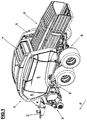
- FIG.1 First, a construction familiar from the prior art can be seen with a drawbar 2 and a subsequent receiving device 3.
- a tractor is able to attach the large agricultural baler 1 and move over the field B in the direction of travel F.
- the machine main frame 4 located, movably driven machine elements of machine panels 5 are covered.
- the machine panels 5 can be made visually appealing to also offer an aesthetic appeal / distinction to competitors.
- the entire large square baler 1 is supported by means of a chassis 6 to the field B floor. Also visible, but only more clearly visible in the following figure, are the housing 7 for the binding unit 12 and the pressing channel 8.
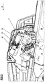
- a conveyor 9 takes the salvaged crop from the receiving device 3 and collects it first a conveyor channel 10.
- the conveyor unit consists of a conveyor rotor and a tine removal unit.
- the plunger 11 moves forward through the associated drive (not shown) in the press channel 8, it is replaced by at least one Part of the conveyor 9 promoted the collected in the conveyor channel 10 crop in the press channel 8. If the plunger 11 is now moved backwards, the newly inserted crop in the press channel 8 is compressed to a Erntegutballen 20.
- the Erntegutballen 20 is additionally wrapped with binding material.
- This housing 7 and the surrounding machine elements are in Figure 3 into focus.
- the generated air flow Q acts in the housing 7 on the binding unit 12 and the surrounding machine elements.
- a portion of the air flow Q passes through the openings for the binding material transfer 21 in the pressing channel 8.
- Another part of the air flow Q is forced by an upper guide element 17 of the guide member 16 to the part of the binding unit 12, where a binder material residue.
- this part of the generated air flow Q promotes the resulting binding material residue on the lower guide element 18 of the channel-like guide element 16 and further on the rear wall of the guide element 16.
- further guide elements 19 favors the removal of the binding material residues by directing the air flow Q in the guide element 16.
- the binding unit 12 is located directly in front of the guide element 16, so that even with discontinuous actuation of the air flow generator 13, a binding material residue can initially be deposited on the lower guide element 18.
- the generated air stream Q now conveys the deposited binding material residue out of the area of the binding unit 12, or out of the housing 7.
- the generated air flow Q passes through the ceiling of the pressing channel 8 located beneath the binding unit 12 can.
- further machine elements can be positively influenced by the air flow Q. For example, with a sufficient volume of the airflow Q, a part of the plunger 11 may be cleaned of dust or like foreign matter.
Landscapes
- Life Sciences & Earth Sciences (AREA)
- Environmental Sciences (AREA)
- Engineering & Computer Science (AREA)
- Mechanical Engineering (AREA)
- Soil Sciences (AREA)
- Harvester Elements (AREA)
- Storage Of Harvested Produce (AREA)
Abstract
Description
- Die Erfindung betrifft eine landwirtschaftliche Großpackenpresse zur Verdichtung von auf dem Feldboden befindlichen Erntematerial wie Stroh, Heu oder dergleichen, welche ein Führungselement zur Aufnahme und zum Abtransport unerwünschten Materials nach dem Oberbegriff des Anspruchs 1 aufweist.
- In der Landwirtschaft sind Großpackenpressen, auch als Quader-, Vierkant- oder Großballenpressen bezeichnet, seit geraumer Zeit bekannt und werden in zahlreichen Varianten eingesetzt. Zu den großen Vorteilen dieser Landmaschinen zählen unter anderem die kontinuierliche Pressarbeit, eine in der Regel hohe Pressdichte und die gute Lagerbarkeit der gefertigten Erntegutballen, Dazu sammeln diese Maschinen zunächst auf dem Feld liegendes Erntegut mit Hilfe einer Aufnahmevorrichtung, landläufig als Pick-Up bekannt, auf. Im Anschluss daran wird das Erntegut von einer Fördereinrichtung übernommen, beispielsweise einem Förderrotor und/oder einer Raffereinheit. Diese fördert das Erntegut in einen zum Presskanal führenden Förderkanal. Sobald der Presskolben weit genug zurückgefahren wurde, wird das gesammelte Erntegut in die Presskammer befördert, wo es durch den Presskolben zu einem Erntegutballen, auch als Quaderballen, Großpacken oder Vierkantballen bezeichnet, verdichtet wird, Damit die Großpacken nach ihrem Ausstoß aus dem Presskanal ihre Form behalten, werden sie mit Bindematerial umschlungen, Dazu wird aktuell insbesondere Garn eingesetzt.
- Wie bei vielen Maschinentypen im landwirtschaftlichen Sektor ist auch bei Großpackenpressen das Bestreben der Hersteller zu erkennen, den Kundenwünschen nach Maschinen mit höherer Leistungsfähigkeit bestmöglich nachzukommen. Mit diesen Anforderungen gehen allerdings auch neue Herausforderungen für die Maschinenhersteller einher. Im Bereich der Großpackenpressen bedeutet erhöhte Leistungsfähigkeit besonders höhere Durchsatzleistung bei größtmöglicher Pressdichte. Die Pressdichte einer Großpackenpresse hängt dabei unter anderem von der Presskraft der Maschine ab. Das eingesetzte Material, mit dem der Erntegutballen umschlungen wird, spielt dabei eine entscheidende Rolle. Diese Garne nehmen, je nach Fabrikat und Qualität, zum Teil Kräfte über 5 kN auf. Da diese Bindematerialien jedoch getrennt und neu verbunden werden müssen, nimmt die maximale Belastbarkeit ab. Diese Problematik tritt besonders bei Bindeeinheiten auf, welche einen Erntegutballen sowohl zum Beginn, als auch zum Ende des Pressvorgangs mit einem Knoten versehen. Diese als "Doppelknoter" bezeichneten Bindeeinheiten erfreuen sich steigender Beliebtheit. Das ist darauf zurückzuführen, dass die Bindeeinheit und das Bindematerial sich während des Pressvorgangs nicht gegenseitig belasten. Die sogenannten "Einfachknoter" versehen den Erntegutballen nur mit einem Knoten, also einem Schwachpunkt. Doch während des Pressvorgangs muss das Bindematerial bei/von der Bindeeinheit gehalten werden, Dadurch sind Bindematerial und -einheit während des gesamten Pressvorgangs belastet und stehen unter Spannung. Hierdurch wird der Verschleiß an den Komponenten der Bindeeinheit erheblich verstärkt. Weiterhin leidet die Belastbarkeit des Bindematerials durch die dauerhafte Strapazierung.
- Durch die Verwendung eines "Doppelknoters" können, ganzheitlich betrachtet, bessere Ergebnisse erzielt werden. Insbesondere bezüglich des Verschleißes der Bindeeinheit und der Belastbarkeit des Bindematerials. Jedoch bringt der "Doppelknoter" einen entscheidenden Nachteil mit sich, der bislang im Stand der Technik nicht hinreichend behandelt wurde. Denn durch das eingesetzte Verfahren der aktuell bekannten und eingesetzten Bindeeinheiten vom Typ "Doppelknoter" bleibt ein Bindematerialrest beim Umschlingen eines Erntegutballens übrig. In der Regel befindet sich die Bindeeinheit oberhalb des Presskanals. Dadurch besteht die Gefahr, dass die erwähnten Bindematerialreste in einen Erntegutballen geraten. Dafür können sowohl Vibrationen der Maschine oder mangelnde Ablagefläche an/ bei der Bindeeinheit verantwortlich sein. Darüber hinaus sind als Reinigungseinheiten eingesetzte Luftstromerzeuger oftmals für dieses Risiko verantwortlich. Diese Luftstromerzeuger sind zumeist als Gebläse ausgeführt, welche Luft entgegen der Fahrtrichtung gegen die Bindeeinheit fördern. Dadurch wird Material entfernt, dass die Bindeeinheit zu blockieren droht. Dazu gehören bei den erwähnten "Doppelknotern" aber auch die zumeist synthetischen Bindematerialreste. Zu versorgende Tiere könnten also das Bindematerial versehentlich fressen. Dieses Bindematerial, bzw. dessen Reste sind nicht/ oder nur schwer verdaulich und können zu erheblichen Problemen bei den Tieren führen.
- Im Stand der Technik ist ein Lösungsansatz für landwirtschaftliche Pressen mit Knoter(n) als Bindeeinheit durch die Patentschrift
US 4,805,391 eröffnet. Dabei sollten, bei als Bindeeinheiten eingesetzten Garnknotern, anfallende Garnreste abgesaugt werden. Durch das zumeist staubige Arbeitsumfeld von Großpackenpressen neigen Bindeeinheiten wie Knoter zu Fehlfunktionen. Um diesen Fehlfunktionen vorzubeugen werden im Bereich der Bindeeinheiten bei Großpackenpressen zuvor erwähnte Reinigungseinrichtungen eingesetzt, die einen Luftstrom im Bereich der Knoter hervorrufen. Hierbei kommen sowohl Drucklufteinrichtungen als auch Gebläse mit konstantem Luftstrom zum Einsatz. Dadurch wird ein Absaugen der Bindematerialreste erschwert oder gar verhindert. Aktuellen Großpackenpressen kann die in der Patentschrift aufgezeigte Lösung daher nicht weiterhelfen. - Aufgabe der vorliegenden Erfindung ist daher, eine landwirtschaftliche Großpackenpresse anzubieten, welche eine benutzerfreundliche und dennoch einfache Möglichkeit zur Bewältigung der im Stand der Technik auftretenden Herausforderungen anbietet, indem eine Reinigungseinheit um eine einfache Baugruppe ergänzt wird und sowohl zur Reinigung der Bindeeinheit beiträgt, als auch sicher verhindert, dass Bindematerialreste in einen zu pressenden Großpacken geraten.
- Die Aufgabe wird durch eine landwirtschaftliche Großpackenpresse gemäß den Merkmalen des Anspruchs 1 gelöst, wobei vorteilhafte Weiterbildungen aus den weiteren Patentansprüchen und den Ausführungsbeispielen hervorgehen. In den folgenden Ausführungsbeispielen und Beschreibungen sind Angaben wie "oben", "unten", "links", "rechts", "vorne" und "hinten" bezogen auf eine landwirtschaftliche Großpackenpresse mit der Zugdeichsel in Fahrtrichtung weisend zu verstehen.
- Die erfindungsgemäße, landwirtschaftliche Großpackenpresse ist ausgestattet mit einem Fahrwerk zum Abstützen der Großpackenpresse auf dem Feldboden, einer Aufnahmevorrichtung zum Bergen von auf dem Feldboden liegenden Erntegut, wenigstens einer Fördereinrichtung zur Beförderung des geborgenen Ernteguts in einen Presskanal, in welchem ein hin und her beweglich angetriebener Presskolben dazu ausgelegt ist, das Erntegut zu einem Erntegutballen zu verdichten, mit wenigstens einer dem Presskanal zugeordneten Bindeeinheit zur Umreifung des Erntegut mit Bindematerial, sowie wenigstens einem Luftstromerzeuger zur Reinigung der Bindeeinheit, wobei der Bindeeinheit ein Führungselement zugeordnet ist, welches unerwünschtes Material aufnimmt und durch den vom Luftstromerzeuger hervorgebrachten Luftstrom von der Bindeeinheit wegleitet.
- Gemäß der Erfindung wird eine landwirtschaftliche Großpackenpresse zunächst mit einem Luftstromerzeuger, ausgeführt als Reinigungsgebläse, für die Bindeeinheit ausgestattet. Dieses Reinigungsgebläse ist im besten Fall mit seiner Förderrichtung leicht in Fahrtrichtung der Großpackenpresse ausgerichtet. An der Bindeeinheit angeordnet befindet sich ein erfindungsgemäßes Führungselement. Idealerweise wird ein derartiges Führungselement als eine Art Luftkanal oder -schacht ausgeführt. Dieses Führungselement liegt dabei mit seiner tiefsten Stelle unterhalb der Position der Bindeeinheit von der die Bindematerialreste ausgehen. Von dieser tiefsten Stelle des Führungselements werden bevorzugt Fortsätze zu der Stelle geführt, an der Bindematerialreste durch die Bindeeinheit entstehen. Im Optimalfall kann nun nach einem ausgelösten Bindevorgang der Bindematerialrest direkt auf dem dazugehörigen Fortsatz des Führungselements abgelegt werden. Geschickter Weise fördert der konstant arbeitende Luftstromerzeuger die abgelegten oder anderweitig von den Fortsätzen aufgefangenen Bindematerialreste in das Führungselement, An der Rückwand des Führungselements angelangt, können die Bindematerialreste durch verschieden ausgeführte Anwendungen entfernt werden.
- Bevorzugt wird auch hierbei die Kombination des Führungselements mit einem Luftstromerzeuger in Form eines konstant arbeitenden Gebläses. Die Bindeeinheit wird dabei von einem Gehäuse umschlossen. Erfindungsgemäß beherbergt das Gehäuse den Luftstromerzeuger. Der Luftstromerzeuger ist in einer Ausführung dazu ausgelegt, einen stetigen, konstanten Luftstrom zu erzeugen. Allerdings ist auch die Nutzung anderer Luftstromerzeuger denkbar. Denkbar wäre eine Druckluftvorrichtung, welche in regelmäßigen Intervallen die Bindeeinheit reinigt. Weiterhin kann die Druckluftreinigung auch an den Bindevorgang gekoppelt sein. Sinnvoller Weise wird das Gehäuse möglichst luftdicht von der Umgebung abgeschirmt. Dadurch wird ein Überdruck im Bereich der Bindeeinheit erzeugt. Dieser Überdruck hält die staubige Umgebungsluft und Erntegutreste von der Bindeeinheit fern. Wird jetzt das Führungselement mit wenigstens einem Luftauslass versehen, kann der generierte Luftstrom die aufgenommenen Bindematerialreste herausleiten. Sinnvollerweise können dem Führungselement Luftleitelemente hinzugefügt werden. Diese Leitelemente sind beispielsweise als flossenartige Bleche schräg in Richtung Luftauslass gerichtet. So wird der erzeugte Luftstrom derart beeinflusst, dass wenig/oder keine Verwirbelungen entstehen. Der Abtransport der unerwünschten Materialien, wie Bindematerial oder Erntegutreste, erfolgt demnach zügiger.
- Eine besonders bevorzugte Ausführung sieht vor, das Führungselement quer zur Fahrtrichtung anzulegen. Durch den Luftstrom kann das unerwünschte Material also seitlich der Presskammer ausgeworfen werden, ohne in oder auf den zu pressenden Erntegutballen zu gelangen. Dabei können zuvor beschriebene oder ähnliche Luftleitelemente besonders hilfreich sein.
- Insbesondere bei der Verwendung synthetischer Bindematerialien kann selbst der Ausstoß des unerwünschten Materials seitlich oder hinter der Maschine unerwünscht sein. Denn es besteht die Möglichkeit, dass bei einem folgenden Erntevorgang derart entsorgtes Bindematerial, bzw. dessen Reste, beispielsweise durch die Aufnahmevorrichtung einer Landmaschine aufgenommen werden und direkt in den Erntegutfluss gelangen. Daher wird weiterhin vorgeschlagen, das von der Bindeeinheit weisende Ende des Führungselements mit einer Vorrichtung zum Auffangen des unerwünschten Materials auszustatten, In diesem Fall ist auch ein Führungselement denkbar, dessen Luftauslass etwa parallel zur Fahrtrichtung ausgerichtet ist. Durch die Auffangvorrichtung kann auch hier eine Ablage unerwünschten Materials auf den Erntegutballen verhindert werden.
Da bei dem Vorgang der Umreifung die Bindeeinheit durch die als Nadel bekannte Bindematerialübergabe mit Bindematerial versorgt wird, kann Erntegut in den Bereich der Bindeeinheit gelangen. Denn die Bindematerialbeschickung der Bindeeinheit muss durch den Presskanal gelangen, um das Bindematerial an die Bindeeinheit zu übergeben. Wird nun ein Führungselement eingesetzt um unerwünschtes Material abzutransportieren, könnten Erntegutreste einem Presseelement zurückgeführt werden. Bei Bindeeinheiten, die Bindematerialreste erzeugen hingegen, sollten diese Bindematerialreste aufgenommen und gesammelt werden, um Gefahren für Tiere durch Verunreinigung ihres Streus/Futters zu vermeiden. - Um optimale Ergebnisse zu erzielen, wird eine Vorrichtung zum Trennen des bei der Bindeeinheit unerwünschten Materials empfohlen. Zum einen können durch eine Trennung der unerwünschten Materialien Gefäße für die Sammlung von Bindematerialresten in ihrer Größe der landwirtschaftlichen Großpackenpresse angepasst werden. Der Sammelbehälter kann kleiner ausgeführt werden, um bei geringem räumlichen Platz eingesetzt werden zu können. Oder der Sammelbehälter wird trotz Trennung der Bindematerialreste größtmöglich verbaut, um eine längere fehlerlose Einsatzzeit zu ermöglichen. In jedem Fall kann die Einsatzzeit der landwirtschaftlichen Großpackenpresse mit einer derartigen Sammeleinrichtung erhöht werden. Denn die Erntegutreste werden in der Regel eine geringere Masse aufweisen, jedoch durchaus räumlichen Platz in Sammelbehältnissen einnehmen, sollte eine Trennung nicht stattfinden, Da in der Regel die Erntegutreste eine geringere Masse aufweisen als die Bindematerialreste, kann ein zweigeteilter Luftauslass des Führungselements bereits ausreichen, um eine Trennung vorzunehmen. Durch die unterschiedliche Masse der unerwünschten Materialien kann diese Zweiteilung des Luftauslasses idealerweise durch ein horizontales Element erfüllt werden. Demnach wird gemäß dieser vorteilhaften Ausführung ein Sammelbehältnis in dem unteren der beiden Bereiche des Luftauslass des erfindungsgemäßen Führungselements angebracht, Im oberen Bereich kann nun wahlweise eine Vorrichtung zur Rückführung der Erntegutreste in den Erntegutfluss erfolgen. Auch eine Führung des Luftstromanteils mit Erntegutresten ist ausführbar. Durch Leitelemente zum Führen der Erntegutreste können Verschmutzungen weitere Maschinenelemente verhindert oder zumindest vermieden werden.
- Darüber hinaus sind verschiedene Ausführungen von Sammelbehältnissen denkbar. Eine Ausführung aus Metall kann ebenso Vorteile bieten, wie eine Ausführung aus Kunststoff. Eine Ausführung als Metall kann möglicherweise besser befestigt werden. Oder einen verbesserter Widerstand eines metallenen Sammelbehältnisses bezüglich stärkerer Luftströmung kommt in den Sinn. Offensichtliche Vorteile eines Sammelbehältnisses aus Kunststoff wären das verringerte Gewicht dieser Ausführung. Weiterhin sind Kunststoffgewebe sicher durch ihr geringes Gewicht und ihre Flexibilität vorteilhaft. Darüber hinaus könnte ein Kunststoffgewebe grobmaschig genug ausgeführt sein, um den Luftstrom bis zur Füllung des Sammelbehältnisses hindurch zu lassen. Dadurch können Verwirbelungen vermieden werden, welche sonst möglicherweise die gesammelten Bindematerialreste wieder auf den Erntegutballen oder in die Umwelt abgeben.
Bezugszelchenllste: 1. Großpackenpresse Q - Luftstrom 2. Zugdeichsel F - Fahrtrichtung 3. Aufnahmevorrichtung B - Feldboden 4. Maschinenhauptrahmen 5. Maschinenverkleidung 6. Fahrwerk 7. Gehäuse 8. Presskanal 9. Fördereinrichtung 10. Förderkanal 11. Presskolben 12. Bindeeinheit 13. Luftstromerzeuger 14. Rotorblatt 15. Antrieb 16. Führungselement 17. Oberes Leitelement 18. Unteres Leitelement 19. Inneres Leitelement 20. Erntegutballen 21. Bindematerialübergabe (Nadel) - Nachfolgend wird eine bevorzugte Ausführungsform der Erfindung anhand einiger Zeichnungen näher beschrieben. Die Zeichnungen zeigen:
-
FIG.1 : eine perspektivische Ansicht einer landwirtschaftlichen Großpackenpresse ohne einen Großteil der Schutzverkleidung, sodass die Position der Bindeeinheit und des dazugehörigen Luftstromerzeuger sichtbar wird; -
FIG.2 : eine Ansicht im Längsschnitt zur weiteren Verdeutlichung der Positionierung und Funktionsweise des Luftstromerzeugers und einem erfindungsgemäßen Führungselement; -
FIG.3 : eine erfindungsgemäße Bindeeinheit mit dazugehörigem Luftstromerzeuger und erfindungsgemäßem Führungselement zum Entfernen von unerwünschtem Material. - In
FIG.1 wird eine landwirtschaftliche Großpackenpresse 1 gemäß der Erfindung, Zunächst lässt sich ein aus dem Stand der Technik vertrauter Aufbau mit einer Zugdeichsel 2 und einer darauf folgenden Aufnahmevorrichtung 3 erkennen. Durch diese Zugdeichsel 2 ist eine Zugmaschine in der Lage, die landwirtschaftliche Großpackenpresse 1 anzuhängen und über den Feldboden B in Fahrtrichtung F zu bewegen. Aus Sicherheitsgründen werden die am Maschinenhauptrahmen 4 befindlichen, beweglich angetriebenen Maschinenelemente von Maschinenverkleidungen 5 verdeckt. Nebenbei können die Maschinenverkleidungen 5 optisch ansprechend gestaltet werden, um auch einen ästhetischen Anreiz/ eine optische Unterscheidungskraft zu Mitbewerbern anzubieten. Die gesamte Großpackenpresse 1 stützt sich mit Hilfe eines Fahrwerks 6 zum Feldboden B ab. Ebenfalls sichtbar, aber erst in der folgenden Figur genauer erkennbar, sind das Gehäuse 7 für die Bindeeinheit 12 und der Presskanal 8. - Nachdem das Erntegut von der Aufnahmevorrichtung 3 vom Feldboden B aufgelesen ist, lässt sich durch die
FIG.2 die weitere Funktionsweise nachvollziehen. Eine Fördereinrichtung 9 übernimmt das geborgene Erntegut von der Aufnahmevorrichtung 3 und sammelt es zunächst ein einem Förderkanal 10. In der Darstellung besteht die Fördereinheit aus einem Förderrotor und einer Zinkenraffereinheit. Sobald der Presskolben 11 durch den dazugehörigen Antrieb (nicht dargestellt) im Presskanal 8 nach vorne verfährt, wird durch zumindest einen Teil der Fördereinrichtung 9 das im Förderkanal 10 gesammelte Erntegut in den Presskanal 8 gefördert. Wird der Presskolben 11 jetzt wieder nach hinten bewegt, wird das grade eingeschobene Erntegut im Presskanal 8 zu einem Erntegutballen 20 verdichtet. Der Erntegutballen 20 wird zusätzlich mit Bindematerial umschlungen. Das geschieht, damit der Erntegutballen 20 nach dem Verlassen des Presskanals 8 seine Form nicht verliert und/oder zerfällt. Um das Bindematerial von unterhalb eines zu umschlingenden Erntegutballen 20 hinauf zur oberhalb des Presskanals 8 angeordneten Bindeeinheit 12 zu befördern, werden Elemente zur Bindematerialübergabe 21 eingesetzt. Diese Bindematerialübergabe 21 wird für gewöhnlich als "Nadel" bezeichnet, da sie das Bindematerial, zumeist also einen Garnfaden durch den Presskanal 8 durchreicht. Zur besseren Übersicht ist an dieser Stelle die Maschinenverkleidung 5 weggelassen. Lediglich das Gehäuse 7 des Luftstromerzeugers 13 wird dargestellt. - Dieses Gehäuse 7 und die umgebenden Maschinenelemente werden in
Fig.3 in den Fokus gerückt. Durch die Darstellung des erfindungsgemäßen, größtenteils luftdicht ausgeführten Gehäuses 7 und des dazugehörigen Luftstromerzeugers 13, wird auch deutlich, wie der erzeugte Luftstrom Q erfindungsgemäß im Gehäuse 7 auf die Bindeeinheit 12 und die umgebenden Maschinenelemente wirkt. Ein Teil des Luftstroms Q gelangt durch die Öffnungen für die Bindematerialübergabe 21 in den Presskanal 8. Ein weiterer Teil des Luftstroms Q wird durch ein oberes Leitelement 17 des Führungselementes 16 an den Teil der Bindeeinheit 12 gezwungen, an dem ein Bindematerialrest entsteht. Dadurch fördert dieser Teil des erzeugten Luftstroms Q den entstehenden Bindematerialrest auf das untere Leitelement 18 des kanalartigen Führungselements 16 und weiter an die Rückwand des Führungselements 16. Durch den Einsatz weiterer Leitelemente 19 wird der Abtransport der Bindematerialreste durch Leitung des Luftstroms Q im Führungselement 16 begünstigt. Die Bindeeinheit 12 liegt direkt vor dem Führungselement 16, sodass auch bei diskontinuierlicher Betätigung des Luftstromerzeugers 13 ein Bindematerialrest zunächst auf dem unteren Leitelement 18 abgelegt werden kann. In jedem Fall fördert der erzeugte Luftstrom Q den abgelegten Bindematerialrest nun aus dem Bereich der Bindeeinheit 12, bzw. aus dem Gehäuse 7. Weiterhin lässt sich erkennen, dass der erzeugte Luftstrom Q durch die unterhalb der Bindeeinheit 12 befindliche Decke des Presskanals 8 gelangen kann. Dadurch können weitere Maschinenelemente positiv von dem Luftstrom Q beeinflusst werden. Beispielsweise kann bei ausreichendem Volumen des Luftstroms Q ein Teil des Presskolbens 11 von Staub oder ähnlichen Fremdkörpern gereinigt werden. Ebenso können Verschmutzungen des Ernteguts vermindert werden, indem Erntegut, welches aus dem Förderkanal 10 in den Presskanal 8 geschoben wird im noch gering verdichteten Zustand durchströmt werden, bevor es durch den Presskolben 11 im Presskanal zu einem Erntegutballen 20 verdichtet wird.
Claims (10)
- Landwirtschaftliche Großpackenpresse (1) mit einem Fahrwerk (6) zum Abstützen der Großpackenpresse (1) auf dem Feldboden (B), einer Aufnahmevorrichtung (3) zum Bergen von auf dem Feldboden (B) liegenden Erntegut, wenigstens einer Fördereinrichtung (4) zur Beförderung des geborgenen Ernteguts in einen Presskanal (8), in welchem ein hin und her beweglich angetriebener Presskolben (11) dazu ausgelegt ist, das Erntegut zu einem Erntegutballen (20) zu verdichten, mit wenigstens einer dem Presskanal (8) zugeordneten Bindeeinheit (12) zur Umreifung des Erntegutballens (20) mit Bindematerial, sowie wenigstens einem Luftstromerzeuger (13) zur Reinigung der Bindeeinheit (12), dadurch gekennzeichnet, dass der Bindeeinheit (12) ein Führungselement (16) zugeordnet ist, welches unerwünschtes Material aufnimmt und durch den vom Luftstromerzeuger (13) hervorgebrachten Luftstrom (Q) von der Bindeeinheit (12) wegleitet.
- Landwirtschaftliche Großpackenpresse (1) nach Anspruch 1, dadurch gekennzeichnet, dass der Luftstromerzeuger (13) dazu eingerichtet ist, unerwünschtes Material in zumindest einer dem Bindevorgang angepassten Frequenz durch Erzeugung eines Luftstroms (Q) von der Bindeeinheit (12) in Richtung des Führungselementes (16) zu fördern.
- Landwirtschaftliche Großpackenpresse (1) nach Anspruch 1 oder 2, dadurch gekennzeichnet, dass das Führungselement (16) derart ausgeformt ist, das unerwünschtes Material seitlich zur Fahrtrichtung (F) der Großpackenpresse (1) entfernt wird.
- Landwirtschaftliche Großpackenpresse (1) nach zumindest einem der vorherigen Ansprüche, dadurch gekennzeichnet, dass das Führungselement (6), in das der ausgegebene Luftstrom (Q) des Luftstromerzeugers (13) unerwünschtes Material transportiert, kanalartig ausgebildet ist.
- Landwirtschaftliche Großpackenpresse (1) nach zumindest einem der vorherigen Ansprüche, dadurch gekennzeichnet, dass das Führungselement (16) derart ausgeführt ist, dass unerwünschtes Material unmittelbar an der Bindeeinheit (12) aufgenommen wird.
- Landwirtschaftliche Großpackenpresse (1) nach zumindest einem der vorherigen Ansprüche, dadurch gekennzeichnet, dass dem Führungselement (16) wenigstens ein Leitelement (17/18/19) zugeordnet ist, welches einen erzeugten Luftstrom (Q) in zumindest eine bevorzugte Richtung leitet.
- Landwirtschaftliche Großpackenpresse (1) nach zumindest einem der vorherigen Ansprüche, dadurch gekennzeichnet, dass dem Führungselement (16) zumindest eine Vorrichtung zum Auffangen von zumindest einem Teil des unerwünschten Materials nachgeordnet ist.
- Landwirtschaftliche Großpackenpresse (1) nach Anspruch 7, dadurch gekennzeichnet, dass die Vorrichtung zum Auffangen von unerwünschtem Material darüber hinaus in der Lage ist, das aufgefangene Material voneinander zu trennen.
- Landwirtschaftliche Großpackenpresse (1) nach zumindest einem der vorherigen Ansprüche, dadurch gekennzeichnet, dass es sich bei unerwünschtem Material um Bindematerialreste oder Erntegutreste handelt.
- Landwirtschaftliche Großpackenpresse (1) nach zumindest einem der Ansprüche 8 und 9, dadurch gekennzeichnet, dass die Trennung von Bindematerialresten und Erntegutresten durch den Luftstrom (Q) wenigstens unterstützt wird.
Applications Claiming Priority (1)
| Application Number | Priority Date | Filing Date | Title |
|---|---|---|---|
| DE102017005667.6A DE102017005667A1 (de) | 2017-06-14 | 2017-06-14 | Landwirtschaftliche Großpackenpresse |
Publications (2)
| Publication Number | Publication Date |
|---|---|
| EP3414993A1 true EP3414993A1 (de) | 2018-12-19 |
| EP3414993B1 EP3414993B1 (de) | 2020-09-30 |
Family
ID=62630887
Family Applications (1)
| Application Number | Title | Priority Date | Filing Date |
|---|---|---|---|
| EP18000513.4A Active EP3414993B1 (de) | 2017-06-14 | 2018-06-12 | Landwirtschaftliche grosspackenpresse |
Country Status (2)
| Country | Link |
|---|---|
| EP (1) | EP3414993B1 (de) |
| DE (1) | DE102017005667A1 (de) |
Cited By (1)
| Publication number | Priority date | Publication date | Assignee | Title |
|---|---|---|---|---|
| DE202020103727U1 (de) | 2020-06-29 | 2021-10-04 | Maschinenfabrik Bernard Krone GmbH & Co. KG | Ballenpresse mit einer Bindevorrichtung und mit einer Fördervorrichtung für Bindemittelreste |
Citations (5)
| Publication number | Priority date | Publication date | Assignee | Title |
|---|---|---|---|---|
| US4805391A (en) * | 1987-04-03 | 1989-02-21 | Ford New Holland, Inc. | Twine tail collector system for agricultural balers |
| US7318376B1 (en) * | 2006-09-12 | 2008-01-15 | Agco Corporation | Knotter blower for agricultural balers |
| EP2289305A1 (de) * | 2009-08-28 | 2011-03-02 | Müthing GmbH & Co. KG | Vorrichtung zur Reinigung einer Ballenpresse |
| EP2709432A1 (de) * | 2011-05-19 | 2014-03-26 | CNH Industrial Belgium nv | Quaderballenpresse mit verbessertem luftfluss nach den astfängern |
| EP3028562A1 (de) * | 2014-12-03 | 2016-06-08 | Usines Claas France S.A.S | Quaderballenpresse |
Family Cites Families (1)
| Publication number | Priority date | Publication date | Assignee | Title |
|---|---|---|---|---|
| DE19528658B4 (de) * | 1995-08-04 | 2005-05-12 | Laverda S.P.A. | Verfahren und Schaltungsanordnung zum Steuern eines Reinigungsgebläses und einer Zentralschmierung für eine Quadergroßballenpresse |
-
2017
- 2017-06-14 DE DE102017005667.6A patent/DE102017005667A1/de not_active Withdrawn
-
2018
- 2018-06-12 EP EP18000513.4A patent/EP3414993B1/de active Active
Patent Citations (5)
| Publication number | Priority date | Publication date | Assignee | Title |
|---|---|---|---|---|
| US4805391A (en) * | 1987-04-03 | 1989-02-21 | Ford New Holland, Inc. | Twine tail collector system for agricultural balers |
| US7318376B1 (en) * | 2006-09-12 | 2008-01-15 | Agco Corporation | Knotter blower for agricultural balers |
| EP2289305A1 (de) * | 2009-08-28 | 2011-03-02 | Müthing GmbH & Co. KG | Vorrichtung zur Reinigung einer Ballenpresse |
| EP2709432A1 (de) * | 2011-05-19 | 2014-03-26 | CNH Industrial Belgium nv | Quaderballenpresse mit verbessertem luftfluss nach den astfängern |
| EP3028562A1 (de) * | 2014-12-03 | 2016-06-08 | Usines Claas France S.A.S | Quaderballenpresse |
Cited By (1)
| Publication number | Priority date | Publication date | Assignee | Title |
|---|---|---|---|---|
| DE202020103727U1 (de) | 2020-06-29 | 2021-10-04 | Maschinenfabrik Bernard Krone GmbH & Co. KG | Ballenpresse mit einer Bindevorrichtung und mit einer Fördervorrichtung für Bindemittelreste |
Also Published As
| Publication number | Publication date |
|---|---|
| DE102017005667A1 (de) | 2018-12-20 |
| EP3414993B1 (de) | 2020-09-30 |
Similar Documents
| Publication | Publication Date | Title |
|---|---|---|
| DE1782382C3 (de) | Ladewagen mit einer ballenbildenden Ladeeinrichtung | |
| DE69709981T2 (de) | Rundballenpresse | |
| EP2289305B1 (de) | Vorrichtung zur Reinigung einer Ballenpresse | |
| DE1160229C2 (de) | Verfahren zum aufladen, pressen und horizontalen verteilen von landwirtschaftlichem halm- und blattgut auf einen transportwagen und landwirtschaftliches transportfahrzeug zur durchfuehrung dieses verfahrens | |
| EP1932419B1 (de) | Landwirtschaftliche Presse | |
| DE3519356C2 (de) | Preßstempel-Reinigungsvorrichtung für eine Ballenpresse mit Zuführung von unten | |
| DE4102034A1 (de) | Rundballenpresse | |
| DE68910003T2 (de) | Ballenpresse. | |
| EP1557080B1 (de) | Ballenpresse | |
| EP2742794B1 (de) | Landwirtschaftliche Erntemaschine und Verfahren zum Warten einer solchen Erntemaschine | |
| EP2556741B1 (de) | Landwirtschaftliche Rundballenpresse | |
| DE102007031211B4 (de) | Ballenpresse | |
| EP3414993B1 (de) | Landwirtschaftliche grosspackenpresse | |
| EP2659762B1 (de) | Landwirtschaftliche Erntemaschine mit Schneidvorrichtung | |
| EP2659763B1 (de) | Erntemaschine mit einer Schneidvorrichtung | |
| DE4312991A1 (de) | Verfahren und Presse zum Bilden quaderförmiger Preßballen aus landwirtschaftlichem Erntegut | |
| EP4282248A1 (de) | Rundballenpresse | |
| EP3959961B1 (de) | Halmgutpresse mit entnehmbarem schneidmodul und verfahren zur handhabung eines solchen entnehmbaren schneidmoduls | |
| EP4183244A1 (de) | Rundballenpresse | |
| EP3414992B1 (de) | Landwirtschaftliche grosspackenpresse | |
| DE102021121746A1 (de) | Landwirtschaftliche Ballenpresse | |
| DE102021106061A1 (de) | Fördervorrichtung für eine ballenpresse | |
| EP3732955B1 (de) | Ballenpresse für landwirtschaftliches erntegut | |
| EP3575073B1 (de) | Ballenausstosseinrichtung und ballenpresse | |
| DE102004023760B4 (de) | Erntemaschine zum Aufnehmen von landwirtschaftlichem Erntegut |
Legal Events
| Date | Code | Title | Description |
|---|---|---|---|
| PUAI | Public reference made under article 153(3) epc to a published international application that has entered the european phase |
Free format text: ORIGINAL CODE: 0009012 |
|
| STAA | Information on the status of an ep patent application or granted ep patent |
Free format text: STATUS: THE APPLICATION HAS BEEN PUBLISHED |
|
| AK | Designated contracting states |
Kind code of ref document: A1 Designated state(s): AL AT BE BG CH CY CZ DE DK EE ES FI FR GB GR HR HU IE IS IT LI LT LU LV MC MK MT NL NO PL PT RO RS SE SI SK SM TR |
|
| AX | Request for extension of the european patent |
Extension state: BA ME |
|
| STAA | Information on the status of an ep patent application or granted ep patent |
Free format text: STATUS: REQUEST FOR EXAMINATION WAS MADE |
|
| 17P | Request for examination filed |
Effective date: 20190614 |
|
| RBV | Designated contracting states (corrected) |
Designated state(s): AL AT BE BG CH CY CZ DE DK EE ES FI FR GB GR HR HU IE IS IT LI LT LU LV MC MK MT NL NO PL PT RO RS SE SI SK SM TR |
|
| STAA | Information on the status of an ep patent application or granted ep patent |
Free format text: STATUS: EXAMINATION IS IN PROGRESS |
|
| 17Q | First examination report despatched |
Effective date: 20191031 |
|
| GRAP | Despatch of communication of intention to grant a patent |
Free format text: ORIGINAL CODE: EPIDOSNIGR1 |
|
| STAA | Information on the status of an ep patent application or granted ep patent |
Free format text: STATUS: GRANT OF PATENT IS INTENDED |
|
| INTG | Intention to grant announced |
Effective date: 20200520 |
|
| GRAS | Grant fee paid |
Free format text: ORIGINAL CODE: EPIDOSNIGR3 |
|
| GRAA | (expected) grant |
Free format text: ORIGINAL CODE: 0009210 |
|
| STAA | Information on the status of an ep patent application or granted ep patent |
Free format text: STATUS: THE PATENT HAS BEEN GRANTED |
|
| AK | Designated contracting states |
Kind code of ref document: B1 Designated state(s): AL AT BE BG CH CY CZ DE DK EE ES FI FR GB GR HR HU IE IS IT LI LT LU LV MC MK MT NL NO PL PT RO RS SE SI SK SM TR |
|
| REG | Reference to a national code |
Ref country code: CH Ref legal event code: EP Ref country code: GB Ref legal event code: FG4D Free format text: NOT ENGLISH |
|
| REG | Reference to a national code |
Ref country code: AT Ref legal event code: REF Ref document number: 1317806 Country of ref document: AT Kind code of ref document: T Effective date: 20201015 |
|
| REG | Reference to a national code |
Ref country code: DE Ref legal event code: R096 Ref document number: 502018002554 Country of ref document: DE |
|
| REG | Reference to a national code |
Ref country code: IE Ref legal event code: FG4D Free format text: LANGUAGE OF EP DOCUMENT: GERMAN |
|
| REG | Reference to a national code |
Ref country code: NL Ref legal event code: FP |
|
| PG25 | Lapsed in a contracting state [announced via postgrant information from national office to epo] |
Ref country code: BG Free format text: LAPSE BECAUSE OF FAILURE TO SUBMIT A TRANSLATION OF THE DESCRIPTION OR TO PAY THE FEE WITHIN THE PRESCRIBED TIME-LIMIT Effective date: 20201230 Ref country code: SE Free format text: LAPSE BECAUSE OF FAILURE TO SUBMIT A TRANSLATION OF THE DESCRIPTION OR TO PAY THE FEE WITHIN THE PRESCRIBED TIME-LIMIT Effective date: 20200930 Ref country code: HR Free format text: LAPSE BECAUSE OF FAILURE TO SUBMIT A TRANSLATION OF THE DESCRIPTION OR TO PAY THE FEE WITHIN THE PRESCRIBED TIME-LIMIT Effective date: 20200930 Ref country code: FI Free format text: LAPSE BECAUSE OF FAILURE TO SUBMIT A TRANSLATION OF THE DESCRIPTION OR TO PAY THE FEE WITHIN THE PRESCRIBED TIME-LIMIT Effective date: 20200930 Ref country code: NO Free format text: LAPSE BECAUSE OF FAILURE TO SUBMIT A TRANSLATION OF THE DESCRIPTION OR TO PAY THE FEE WITHIN THE PRESCRIBED TIME-LIMIT Effective date: 20201230 Ref country code: GR Free format text: LAPSE BECAUSE OF FAILURE TO SUBMIT A TRANSLATION OF THE DESCRIPTION OR TO PAY THE FEE WITHIN THE PRESCRIBED TIME-LIMIT Effective date: 20201231 |
|
| PG25 | Lapsed in a contracting state [announced via postgrant information from national office to epo] |
Ref country code: RS Free format text: LAPSE BECAUSE OF FAILURE TO SUBMIT A TRANSLATION OF THE DESCRIPTION OR TO PAY THE FEE WITHIN THE PRESCRIBED TIME-LIMIT Effective date: 20200930 Ref country code: LV Free format text: LAPSE BECAUSE OF FAILURE TO SUBMIT A TRANSLATION OF THE DESCRIPTION OR TO PAY THE FEE WITHIN THE PRESCRIBED TIME-LIMIT Effective date: 20200930 |
|
| REG | Reference to a national code |
Ref country code: LT Ref legal event code: MG4D |
|
| PG25 | Lapsed in a contracting state [announced via postgrant information from national office to epo] |
Ref country code: PT Free format text: LAPSE BECAUSE OF FAILURE TO SUBMIT A TRANSLATION OF THE DESCRIPTION OR TO PAY THE FEE WITHIN THE PRESCRIBED TIME-LIMIT Effective date: 20210201 Ref country code: RO Free format text: LAPSE BECAUSE OF FAILURE TO SUBMIT A TRANSLATION OF THE DESCRIPTION OR TO PAY THE FEE WITHIN THE PRESCRIBED TIME-LIMIT Effective date: 20200930 Ref country code: CZ Free format text: LAPSE BECAUSE OF FAILURE TO SUBMIT A TRANSLATION OF THE DESCRIPTION OR TO PAY THE FEE WITHIN THE PRESCRIBED TIME-LIMIT Effective date: 20200930 Ref country code: EE Free format text: LAPSE BECAUSE OF FAILURE TO SUBMIT A TRANSLATION OF THE DESCRIPTION OR TO PAY THE FEE WITHIN THE PRESCRIBED TIME-LIMIT Effective date: 20200930 Ref country code: SM Free format text: LAPSE BECAUSE OF FAILURE TO SUBMIT A TRANSLATION OF THE DESCRIPTION OR TO PAY THE FEE WITHIN THE PRESCRIBED TIME-LIMIT Effective date: 20200930 Ref country code: LT Free format text: LAPSE BECAUSE OF FAILURE TO SUBMIT A TRANSLATION OF THE DESCRIPTION OR TO PAY THE FEE WITHIN THE PRESCRIBED TIME-LIMIT Effective date: 20200930 |
|
| PG25 | Lapsed in a contracting state [announced via postgrant information from national office to epo] |
Ref country code: ES Free format text: LAPSE BECAUSE OF FAILURE TO SUBMIT A TRANSLATION OF THE DESCRIPTION OR TO PAY THE FEE WITHIN THE PRESCRIBED TIME-LIMIT Effective date: 20200930 Ref country code: AL Free format text: LAPSE BECAUSE OF FAILURE TO SUBMIT A TRANSLATION OF THE DESCRIPTION OR TO PAY THE FEE WITHIN THE PRESCRIBED TIME-LIMIT Effective date: 20200930 Ref country code: IS Free format text: LAPSE BECAUSE OF FAILURE TO SUBMIT A TRANSLATION OF THE DESCRIPTION OR TO PAY THE FEE WITHIN THE PRESCRIBED TIME-LIMIT Effective date: 20210130 Ref country code: PL Free format text: LAPSE BECAUSE OF FAILURE TO SUBMIT A TRANSLATION OF THE DESCRIPTION OR TO PAY THE FEE WITHIN THE PRESCRIBED TIME-LIMIT Effective date: 20200930 |
|
| PG25 | Lapsed in a contracting state [announced via postgrant information from national office to epo] |
Ref country code: SK Free format text: LAPSE BECAUSE OF FAILURE TO SUBMIT A TRANSLATION OF THE DESCRIPTION OR TO PAY THE FEE WITHIN THE PRESCRIBED TIME-LIMIT Effective date: 20200930 |
|
| REG | Reference to a national code |
Ref country code: DE Ref legal event code: R097 Ref document number: 502018002554 Country of ref document: DE |
|
| PLBE | No opposition filed within time limit |
Free format text: ORIGINAL CODE: 0009261 |
|
| STAA | Information on the status of an ep patent application or granted ep patent |
Free format text: STATUS: NO OPPOSITION FILED WITHIN TIME LIMIT |
|
| PG25 | Lapsed in a contracting state [announced via postgrant information from national office to epo] |
Ref country code: DK Free format text: LAPSE BECAUSE OF FAILURE TO SUBMIT A TRANSLATION OF THE DESCRIPTION OR TO PAY THE FEE WITHIN THE PRESCRIBED TIME-LIMIT Effective date: 20200930 |
|
| 26N | No opposition filed |
Effective date: 20210701 |
|
| PG25 | Lapsed in a contracting state [announced via postgrant information from national office to epo] |
Ref country code: IT Free format text: LAPSE BECAUSE OF FAILURE TO SUBMIT A TRANSLATION OF THE DESCRIPTION OR TO PAY THE FEE WITHIN THE PRESCRIBED TIME-LIMIT Effective date: 20200930 |
|
| PG25 | Lapsed in a contracting state [announced via postgrant information from national office to epo] |
Ref country code: SI Free format text: LAPSE BECAUSE OF FAILURE TO SUBMIT A TRANSLATION OF THE DESCRIPTION OR TO PAY THE FEE WITHIN THE PRESCRIBED TIME-LIMIT Effective date: 20200930 |
|
| PG25 | Lapsed in a contracting state [announced via postgrant information from national office to epo] |
Ref country code: MC Free format text: LAPSE BECAUSE OF FAILURE TO SUBMIT A TRANSLATION OF THE DESCRIPTION OR TO PAY THE FEE WITHIN THE PRESCRIBED TIME-LIMIT Effective date: 20200930 |
|
| REG | Reference to a national code |
Ref country code: CH Ref legal event code: PL |
|
| PG25 | Lapsed in a contracting state [announced via postgrant information from national office to epo] |
Ref country code: LU Free format text: LAPSE BECAUSE OF NON-PAYMENT OF DUE FEES Effective date: 20210612 |
|
| PG25 | Lapsed in a contracting state [announced via postgrant information from national office to epo] |
Ref country code: LI Free format text: LAPSE BECAUSE OF NON-PAYMENT OF DUE FEES Effective date: 20210630 Ref country code: IE Free format text: LAPSE BECAUSE OF NON-PAYMENT OF DUE FEES Effective date: 20210612 Ref country code: CH Free format text: LAPSE BECAUSE OF NON-PAYMENT OF DUE FEES Effective date: 20210630 |
|
| PG25 | Lapsed in a contracting state [announced via postgrant information from national office to epo] |
Ref country code: IS Free format text: LAPSE BECAUSE OF FAILURE TO SUBMIT A TRANSLATION OF THE DESCRIPTION OR TO PAY THE FEE WITHIN THE PRESCRIBED TIME-LIMIT Effective date: 20210130 |
|
| GBPC | Gb: european patent ceased through non-payment of renewal fee |
Effective date: 20220612 |
|
| PG25 | Lapsed in a contracting state [announced via postgrant information from national office to epo] |
Ref country code: GB Free format text: LAPSE BECAUSE OF NON-PAYMENT OF DUE FEES Effective date: 20220612 |
|
| P01 | Opt-out of the competence of the unified patent court (upc) registered |
Effective date: 20230517 |
|
| PG25 | Lapsed in a contracting state [announced via postgrant information from national office to epo] |
Ref country code: CY Free format text: LAPSE BECAUSE OF FAILURE TO SUBMIT A TRANSLATION OF THE DESCRIPTION OR TO PAY THE FEE WITHIN THE PRESCRIBED TIME-LIMIT Effective date: 20200930 |
|
| PG25 | Lapsed in a contracting state [announced via postgrant information from national office to epo] |
Ref country code: HU Free format text: LAPSE BECAUSE OF FAILURE TO SUBMIT A TRANSLATION OF THE DESCRIPTION OR TO PAY THE FEE WITHIN THE PRESCRIBED TIME-LIMIT; INVALID AB INITIO Effective date: 20180612 |
|
| PG25 | Lapsed in a contracting state [announced via postgrant information from national office to epo] |
Ref country code: MK Free format text: LAPSE BECAUSE OF FAILURE TO SUBMIT A TRANSLATION OF THE DESCRIPTION OR TO PAY THE FEE WITHIN THE PRESCRIBED TIME-LIMIT Effective date: 20200930 |
|
| PG25 | Lapsed in a contracting state [announced via postgrant information from national office to epo] |
Ref country code: TR Free format text: LAPSE BECAUSE OF FAILURE TO SUBMIT A TRANSLATION OF THE DESCRIPTION OR TO PAY THE FEE WITHIN THE PRESCRIBED TIME-LIMIT Effective date: 20200930 |
|
| REG | Reference to a national code |
Ref country code: AT Ref legal event code: MM01 Ref document number: 1317806 Country of ref document: AT Kind code of ref document: T Effective date: 20230612 |
|
| PG25 | Lapsed in a contracting state [announced via postgrant information from national office to epo] |
Ref country code: MT Free format text: LAPSE BECAUSE OF FAILURE TO SUBMIT A TRANSLATION OF THE DESCRIPTION OR TO PAY THE FEE WITHIN THE PRESCRIBED TIME-LIMIT Effective date: 20200930 |
|
| PG25 | Lapsed in a contracting state [announced via postgrant information from national office to epo] |
Ref country code: AT Free format text: LAPSE BECAUSE OF NON-PAYMENT OF DUE FEES Effective date: 20230612 |
|
| PG25 | Lapsed in a contracting state [announced via postgrant information from national office to epo] |
Ref country code: AT Free format text: LAPSE BECAUSE OF NON-PAYMENT OF DUE FEES Effective date: 20230612 |
|
| PGFP | Annual fee paid to national office [announced via postgrant information from national office to epo] |
Ref country code: DE Payment date: 20250618 Year of fee payment: 8 |
|
| PGFP | Annual fee paid to national office [announced via postgrant information from national office to epo] |
Ref country code: NL Payment date: 20250618 Year of fee payment: 8 Ref country code: BE Payment date: 20250617 Year of fee payment: 8 |
|
| PGFP | Annual fee paid to national office [announced via postgrant information from national office to epo] |
Ref country code: FR Payment date: 20250626 Year of fee payment: 8 |
|
| PGFP | Annual fee paid to national office [announced via postgrant information from national office to epo] |
Ref country code: AT Payment date: 20260410 Year of fee payment: 5 |