EP3414810B1 - System und verfahren zur unterdrückung von netzfrequenzabweichungen - Google Patents
System und verfahren zur unterdrückung von netzfrequenzabweichungen Download PDFInfo
- Publication number
- EP3414810B1 EP3414810B1 EP17710065.8A EP17710065A EP3414810B1 EP 3414810 B1 EP3414810 B1 EP 3414810B1 EP 17710065 A EP17710065 A EP 17710065A EP 3414810 B1 EP3414810 B1 EP 3414810B1
- Authority
- EP
- European Patent Office
- Prior art keywords
- storage
- threshold
- frequency
- grid
- energy
- Prior art date
- Legal status (The legal status is an assumption and is not a legal conclusion. Google has not performed a legal analysis and makes no representation as to the accuracy of the status listed.)
- Active
Links
Images







Classifications
-
- H—ELECTRICITY
- H02—GENERATION; CONVERSION OR DISTRIBUTION OF ELECTRIC POWER
- H02J—ELECTRIC POWER NETWORKS; CIRCUIT ARRANGEMENTS OR SYSTEMS FOR SUPPLYING OR DISTRIBUTING ELECTRIC POWER; SYSTEMS FOR STORING ELECTRIC ENERGY
- H02J3/00—Circuit arrangements for AC mains or AC distribution networks
- H02J3/001—Arrangements for handling faults or abnormalities, e.g. emergencies or contingencies
- H02J3/0014—Arrangements for handling faults or abnormalities, e.g. emergencies or contingencies for preventing or reducing power oscillations in networks
- H02J3/00142—Oscillations concerning frequency
-
- G—PHYSICS
- G05—CONTROLLING; REGULATING
- G05B—CONTROL OR REGULATING SYSTEMS IN GENERAL; FUNCTIONAL ELEMENTS OF SUCH SYSTEMS; MONITORING OR TESTING ARRANGEMENTS FOR SUCH SYSTEMS OR ELEMENTS
- G05B9/00—Safety arrangements
- G05B9/02—Safety arrangements electric
-
- H—ELECTRICITY
- H02—GENERATION; CONVERSION OR DISTRIBUTION OF ELECTRIC POWER
- H02J—ELECTRIC POWER NETWORKS; CIRCUIT ARRANGEMENTS OR SYSTEMS FOR SUPPLYING OR DISTRIBUTING ELECTRIC POWER; SYSTEMS FOR STORING ELECTRIC ENERGY
- H02J3/00—Circuit arrangements for AC mains or AC distribution networks
-
- H—ELECTRICITY
- H02—GENERATION; CONVERSION OR DISTRIBUTION OF ELECTRIC POWER
- H02J—ELECTRIC POWER NETWORKS; CIRCUIT ARRANGEMENTS OR SYSTEMS FOR SUPPLYING OR DISTRIBUTING ELECTRIC POWER; SYSTEMS FOR STORING ELECTRIC ENERGY
- H02J3/00—Circuit arrangements for AC mains or AC distribution networks
- H02J3/28—Arrangements for balancing of the load in networks by storage of energy
- H02J3/30—Arrangements for balancing of the load in networks by storage of energy using dynamo-electric machines coupled to flywheels
-
- H—ELECTRICITY
- H02—GENERATION; CONVERSION OR DISTRIBUTION OF ELECTRIC POWER
- H02J—ELECTRIC POWER NETWORKS; CIRCUIT ARRANGEMENTS OR SYSTEMS FOR SUPPLYING OR DISTRIBUTING ELECTRIC POWER; SYSTEMS FOR STORING ELECTRIC ENERGY
- H02J7/00—Circuit arrangements for charging or discharging batteries or for supplying loads from batteries
- H02J7/865—Battery or charger load switching, e.g. concurrent charging and load supply
-
- H—ELECTRICITY
- H02—GENERATION; CONVERSION OR DISTRIBUTION OF ELECTRIC POWER
- H02J—ELECTRIC POWER NETWORKS; CIRCUIT ARRANGEMENTS OR SYSTEMS FOR SUPPLYING OR DISTRIBUTING ELECTRIC POWER; SYSTEMS FOR STORING ELECTRIC ENERGY
- H02J2103/00—Details of circuit arrangements for mains or AC distribution networks
- H02J2103/30—Simulating, planning, modelling, reliability check or computer assisted design [CAD] of electric power networks
-
- Y—GENERAL TAGGING OF NEW TECHNOLOGICAL DEVELOPMENTS; GENERAL TAGGING OF CROSS-SECTIONAL TECHNOLOGIES SPANNING OVER SEVERAL SECTIONS OF THE IPC; TECHNICAL SUBJECTS COVERED BY FORMER USPC CROSS-REFERENCE ART COLLECTIONS [XRACs] AND DIGESTS
- Y02—TECHNOLOGIES OR APPLICATIONS FOR MITIGATION OR ADAPTATION AGAINST CLIMATE CHANGE
- Y02E—REDUCTION OF GREENHOUSE GAS [GHG] EMISSIONS, RELATED TO ENERGY GENERATION, TRANSMISSION OR DISTRIBUTION
- Y02E60/00—Enabling technologies; Technologies with a potential or indirect contribution to GHG emissions mitigation
-
- Y—GENERAL TAGGING OF NEW TECHNOLOGICAL DEVELOPMENTS; GENERAL TAGGING OF CROSS-SECTIONAL TECHNOLOGIES SPANNING OVER SEVERAL SECTIONS OF THE IPC; TECHNICAL SUBJECTS COVERED BY FORMER USPC CROSS-REFERENCE ART COLLECTIONS [XRACs] AND DIGESTS
- Y04—INFORMATION OR COMMUNICATION TECHNOLOGIES HAVING AN IMPACT ON OTHER TECHNOLOGY AREAS
- Y04S—SYSTEMS INTEGRATING TECHNOLOGIES RELATED TO POWER NETWORK OPERATION, COMMUNICATION OR INFORMATION TECHNOLOGIES FOR IMPROVING THE ELECTRICAL POWER GENERATION, TRANSMISSION, DISTRIBUTION, MANAGEMENT OR USAGE, i.e. SMART GRIDS
- Y04S40/00—Systems for electrical power generation, transmission, distribution or end-user application management characterised by the use of communication or information technologies, or communication or information technology specific aspects supporting them
- Y04S40/20—Information technology specific aspects, e.g. CAD, simulation, modelling, system security
Definitions
- the present disclosure relates to a method and a system, configured to suppress frequency deviations in a power grid relative to a desired frequency behaviour, in particular at hour crossings. Normally a stable frequency behaviour at 50 or 60 Hz, or any other value, is very important. Frequency deviations are associated with imbalances between supply and load of the grid.
- a power grid may extend across national borders, and normally comprises power lines, power supply and a beforehand unknown load.
- the supply may comprise normally a plurality of energy generating facilities, such as very stable and predictable coal or other fossil fuel burning electricity generating facilities and /or nuclear facilities, but also at least somewhat more spurious renewable electricity generating facilities, such as wind, wave and solar power facilities. Other electricity providing facilities can also be comprised.
- the power supply facilities may be exploited by power suppliers.
- the load is defined by the amount of energy consumed or received by power consumers or end users in homes, factories, businesses and the like.
- WO-2014/121794 discloses power generation using wind turbines and supply to a grid with a storage of flywheels or batteries to continuously dampen grid frequency deviations relative to a maximum. Therein the storage is constantly deployed, to also equalize turbine output for supply to the grid.
- energy storage in for example batteries and flywheels appears to have been contemplated only in the framework of conventional primary or secondary controls, exhibiting a fixed time delay and proportional response.
- a varying threshold is set, depending on system parameters that may be dependent on time-of-day, or other considerations, to optimise the method.
- a df threshold is determined.
- storage is deployed to counteract proportionally to the deviation in order to suppress the frequency deviation.
- the algorithm may prepare the storage for the next up or down peak by charging (or discharging) its capacity, preferably to a 50% level. This way the storage can react on both positive or negative df peaks.
- the rate at which the (dis)charging takes place may also be set.
- the threshold value can be dynamically adapted in this manner, for instance depending on the hour of the day. Statistics have shown that the largest peaks always occur on the same hour of the day. At these moments the threshold value can be set to 50 mHz or higher. At other moments during the day the threshold value may be lowered to 20 or 30 mHz. Thus a variable adaptation of the threshold value may correlate with the severity of anticipated peaks, and/or with available storage capacity needed for suppression of practically all peaks under the threshold (or at least practically all peaks, for example 80% of all such peaks), and/or with availability of primary control, et cetera..
- results of simulations and tests have yielded - for a storage configuration of 600MW / 36MWh - a reduction of df peaks of 20,7% and throughout the simulated day of 9,0% (average hourly improvement). Moreover, using this algorithm, deployed Primary Control power is reduced by 29%.
- deployed PCR without added storage controlled on the basis of the threshold can be 1544MW, but deployed PCR with storage controlled based on threshold is anticipated to be 1096MW; a reduction 448 MW].
- variable threshold also proves to have benefits in other contexts than hour crossings.
- flywheel when a frequency deviation or excursion exceeds a threshold, energy is deployed from storage, such as a flywheel or battery.
- a flywheel is a preferred embodiment according to the present disclosure, because flywheels exhibit no or hardly any degradations over time.
- the flywheel is made to charge with energy from the grid or release energy therefrom into the grid, as frequency excursions occur.
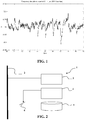
- a system 1, embodying a also a method according to the present disclosure, in an extremely simplified form, comprises a frequency monitor 3, connected to a grid 2, a controller 4 acting on a switch 6, dependent on frequency behaviour on the grid 2 as detected by the frequency monitor 3, to selectively connect energy storage 5 to the grid for storing energy from the grid in the storage 5 or deploying energy from the storage 5 into the grid 2, thereby effecting suppression of frequency excursions as depicted in figure 1 .
- the control 4 may compare instantaneous frequency values with a threshold, for example a 50 mHz threshold relative to the desired stable frequency of for example 50 or 60 Hz, to determine when to connect the storage 5 to the grid 2.
- a threshold for example a 50 mHz threshold relative to the desired stable frequency of for example 50 or 60 Hz
- An advantage of storage 5 over prior art primary control and secondary control is that storage can respond within a matter of milliseconds and can therefore be deployed at any given time. Timing is of importance, as the available power from a storage is limited.
- Instantaneous deployment of a storage has the advantage that the primary (and secondary) controls may be deployed to a much lesser extent or even not at all, thus reserving or conserving the primary and secondary controls for true calamities, emergencies and the like. It is not excluded that the primary and even secondary controls are deployed, for instance to combat larger frequency deviations or deviations that persist for longer periods of time, which the storage cannot combat alone. Such occurrences should therefore be considered emergencies in the sense that the primary and secondary controls are justly deployed.
- Figures 3 and 4 show statistical analysis of frequency behaviour on the grid 2.
- Figure 3 shows negative deviations below 49,95 Hz
- figure 4 shows positive deviations above 50,05 Hz.
- the amount of storage required in the European situation is determined through a statistical analysis in terms of power of the same data on which figures 3 and 4 are based. A bigger data set can be employed, than for one month as in figures 3 and 4 , for example for an entire year or more than one year.
- the threshold frequency is set at 50mHz after which the amount of peaks are determined that surpass this threshold, which results in the graphs of figures 3 and 4 . Also, the duration of the peaks and the amount of power involved was determined. From the same data sets resulting in the graphs of figures 3 and 4 it has been deduced that the maximum amount of power needed to suppress the frequency deviations is 1638MW, on day 30, hour 0 and day 15, hour 23 (negative frequency deviation of figure 3 ). A broader analysis has revealed that a power to energy of 1638 MW / 200 MWh is required for full suppression of all peaks.
- Figures 5 and 6 exemplify graphs indicating amounts of energy needed to suppress frequency deviations to below 50 mHz.
- a maximum of 200 MWh is detectable on day 14, hour 0 (positive frequency deviation of figure 4 ).
- Research and investigations have revealed that this 200MWh peak is at three individual peaks above 50mHz, without recuperation time cause the big energy requirement not found on other days, see figure 7 .
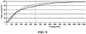
- Optimizing the ratio allows it to be reduced to 0,06 and still cover 80% of peaks (i.e. 85% of positive peaks and 75% of negative peaks), as shown in figure 9 . Further reduction of the ratio will also reduce the coverage.
- the control in figure 2 may analyse changes in frequency on the grid to decide on deployment of the storage when any change relative to a desired value of the frequency occurs.
- a mode that can be designated as proportional to changes in the frequency (df) acts continuously on the grid and reacts at any frequency deviation.
- frequency variations are continuously dampened.
- a df threshold is determined.
- storage is deployed to counteract proportionally to the deviation in order to suppress the frequency deviation.
- the algorithm prepares the storage for the next peak by charging (or discharging) its capacity, preferably to a 50% level. This way the storage can react on both positive or negative df peaks.
- the rate at which the (dis)charging takes place can be set.
- the threshold value can be dynamically adapted depending on the hour of the day. Statistics have shown that the largest peaks always occur on the same hour of the day. At these moments the threshold value can be set to 50 mHz or higher. At other moments during the day the threshold value may be lowered to 20 or 30 mHz.
- Results of simulations and tests have yielded - for a storage configuration of 600MW / 36MWh - a reduction of df peaks of 20,7% and throughout the simulated day of 9,0% (average hourly improvement). Moreover, using this algorithm, the amount of deployed Primary Control power is reduced by 29%. More in particular, deployed PCR without added storage controlled on the basis of the threshold: 1544MW, deployed PCR with storage controlled based on threshold: 1096MW; a reduction 448 MW.
- Figure 10 exhibits in a dashed line 7 in the top graph of figure 10 , an example of an hourly adjusted threshold. This adjustment may be based on an instantaneous response to frequency changes in the grid 2, or statistically based on historical data (see for example figures 3 - 6 ).
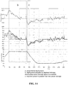
- Figure 11 shows the effect of this scheme on deployment of primary control (PCR), at a single hour crossing. The effects are extra-ordinary.
- the time between a frequency change and the system's follow-up action consists of the steps given below.
- the measured response time and the cause of the duration of the steps is broken down as follows.
- a fast switching IGBT drive was chosen It creates a fairly clean sine and there are no occurrences of 3 rd or 5 th harmonics. Normally, these types of drive create higher harmonics but they are filtered efficiently in the setup of figure 13 .
- Phase balance is another important power quality aspect, and like harmonics, it is fully determined by the drive. In the current setup, there were no significant degradations to the phase balance, and as a result, phase balance was within the measurement error of the Power Quality Analyser (PQA).
- PQA Power Quality Analyser
- test runs of one hour have been defined based on one frequency profile containing 'high' and 'low' frequency deviations in practice and/or based on data sets acquired by grid monitoring beforehand, as well as designed frequency slopes consisting of clean up and down-ramps.
- test runs were due to variations in algorithm parameters, power-to-energy ratios and RPM-levels.
- the results of testing the proportional algorithm are shown in figure 14 .
- the Proportional algorithm behaves as was shown predicted and expected from prior simulations. When looking at zone a in figure 14 it is self evident that storage is following the requested power output perfectly.
- the required power line in the middle graph is visualised as a proportional value derived from the frequency (not in kW).
- the measured power line in the same graph is visualised as actual measured power (in kW).
- the limitations of a proportional algorithm are visible. Considering the fact that the frequency is never stable at 50Hz, this algorithm continuously requires an amount of energy.
- zone b the frequency starts to decline below 50Hz and storage is fully prepared to deploy the countermeasures.
- Figure 15 exemplifies test results for the static threshold level based algorithm.
- the static threshold algorithm also performs as previously simulated. Again, the required power line in the middle graph is shown as a proportional value derived from the frequency (not in kW). The measured power line in the same graph is shown as actual measured power (in kW).
- the second graph shows the amount of actual deployed power vs. requested power and the flywheel is able to follow the algorithm continuously during the complete hour of testing.
- the scale of the storage depletion graph is emphasized here.
- the storage capacity is completely used in this algorithm as well.
- the difference with the proportional algorithm is that the amount of storage was the same for both algorithms, but is only sufficient for this static threshold algorithm.
- Goal of this study is to come to an enhancement of autonomy and performance of the static threshold algorithm through df/dt analysis.
- a data set of at least approximately one year was used to analyse the behaviour of the grid frequency (mainly around the hourly crossings).
- a prior analysis of frequency behaviour of the grid revealed a correlation between peak height and df/dt to some extent.
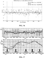
- Figure 16 shows df/dt at a particular hour crossing.
- the detected correlation turned out to be less suitable for predictive storage deployment without taking certain precautionary measures.
- the mathematic approach of finding correlation led to the loss of some extremities in predicted values.
- the predictability could only be found once a 36sec. filter was applied, which was not in favour of the algorithm effectiveness, relying on speed of intervention.
- Hourly crossing profiles differ for every hour of the day. This matches the theory on the origin of these particular frequency deviations as a result of scheduled/stepwise adjustment of generation and import profiles to the daily power requirement (W Dahlbach).
- the direction of the frequency deviations during the day is related to the daily consumption and production patterns and therefore predictable.
- Figure 17 shows an exemplary pattern deducible from data of frequency deviations.
- Values for b and e can be positive or negative. Values for a until f are determined from the data set after normalising the profile to a start frequency of 50,000Hz. Mean and standard deviation values are calculated for values a until f . At phase 1 storage levels will slowly be prepared to its optimum. At phase 2 the optimum threshold point will be determined and set by combining the actual frequency with the reference profile.
- this blueprint will give us a continuously updated reference profile for every hourly crossing to come. It will provide predictive data on the direction of the frequency to determine the optimal storage level; and also a predicted df/dt profile to determine - together with the actual frequency signal - where the initial threshold level must be set.
- the threshold level will be dynamically adjusted every second by comparing the actual df/dt value with the actual storage level. On this comparison, the algorithm will make a decision whether storage deployment must continue based on the same threshold level or if the threshold level need to be fine-tuned.
- the dynamic threshold function is shown in action through the line 8 in the top graph, in comparison with the static algorithm to the left.
- the threshold was set to 0,07 Hz, relative to the desired stable frequency of 50 or 60 Hz.
- an initial value of he threshold was set at 30:00 at its starting value by the algorithm. From this point on, the algorithm increases the threshold to move up gradually until the frequency deviation is mitigated. Results: in comparison with the purely static threshold based algorithm, the presently described dynamic algorithm is 54% more effective on the peak reduction, both in terms of frequency and of PCR (middle graph).
- the slope (df/dt) of the frequency deviations within the hourly crossing originate from the fact that the grid frequency depicts the balance between the gradual variation in energy consumption and the stepwise adaption of the energy generation and import mixes, as shown in figure 23 .
- Figure 25 exhibits a first example of an approach to an hourly crossing, in which all observations are negative. Based on this intelligence, it is possible to anticipate on a negative frequency deviation and prepare the storage load level for 100%.
- Figure 26 exhibits a second example of an hour crossing, in which observations are for the most part in the positive area; a small part is in the negative area. Because the observations in the negative area have small amplitudes it is possible to choose between two options: anticipate on positive frequency deviations only and prepare the storage for 100%, or anticipate on positive frequency deviations and prepare the storage for e.g. 80%, leaving 20% 'room' for small negative deviations. This adaptability provides an extremely enhanced improvement to suppress frequency deviations.
- Figure 27 exhibits yet another situation in which the observations are evenly distributed. The algorithm then prepares a storage level of 50%, which seems adequate and appropriate as the deviation could go either way.
- a threshold level needs to be determined for the deployment of storage. Based on the continuously refreshing analysis an optimal threshold value is available for every hour of the week. By measuring the frequency slope, as shown in figure 28 , immediately after the full hour, the threshold level can be fine-tuned to match the available storage capacity on the energy requirement to suppress the frequency deviation.
- Figure 29 shows an embodiment in which no load management (no dynamic adaptation of the threshold) is applied: after every deployment a 50% load level is restored.
- figure 30 exhibits optimal preparation of the load level, through dynamic adaptation of the threshold as described above, thereby making available a full storage capacity in crucial moments. The full storage capacity is then available to put on or extract energy from the grid, to enable suppression of frequency deviations. The result constitutes an improvement of -100% on df reduction with same storage capacity.
- the algorithm sets a response to frequency deviations from the storage, in which the response is proportional to the deviations, whereas in full anticipation, the response from the storage is to insert or extract its full capacity.
- the predicted peak height and time are used to calculate a threshold level that will allow the storage to mitigate the predicted peak completely.
- the actual frequency level is measured in phase 2 of the hourly crossing, and used to translate the value to the prediction.
- the actual capacity of the storage must match the surface the triangle in figure 28 , thus fixing the threshold level in the equation.
- the predicted threshold values will be fine-tuned during the hourly crossing comparing measurements of actual storage level and actual df/dt.
- the invention could be implemented using a very quickly deployable supply or generator, which can be deployed more quickly than supplies currently available.
- a reserve generator may be coupled with a flywheel for replenishing more quickly the charge of the flywheel than from the grid after deployment and having been drained.
Landscapes
- Engineering & Computer Science (AREA)
- Power Engineering (AREA)
- Physics & Mathematics (AREA)
- General Physics & Mathematics (AREA)
- Automation & Control Theory (AREA)
- Supply And Distribution Of Alternating Current (AREA)
- Remote Monitoring And Control Of Power-Distribution Networks (AREA)
- Charge And Discharge Circuits For Batteries Or The Like (AREA)
Claims (15)
- Verfahren zur Unterdrückung von Netzfrequenzabweichungen (2) relativ zu einem gewünschten Frequenzverhalten, insbesondere bei Stundenübergängen, wobei ein Energiespeicher (5) mit dem Netz verbunden ist, und wobei das Verfahren umfasst:- Überwachen einer Frequenz in dem Netz (2) relativ zu dem gewünschten Frequenzverhalten, um detektierte Frequenzabweichungen zu bestimmen;- Vergleichen von detektierten Frequenzabweichungen mit einem Schwellenwert; - Einsetzen des Speichers (5), um darin Energie aus dem Netz zu laden oder um Energie davon in das Netz zu entladen, wenn detektierte Frequenzabweichungen den Schwellenwert überschreiten; und- Einstellen eines variablen Schwellenwerts,GEKENNZEICHNET DURCH- statistisches Bestimmen, aus historischen Verhaltensdaten von dem Netz und/oder aus dem Verfahren, wann im Rahmen einer Zeitdauer größere und kleinere Frequenzabweichungen statistisch auftreten, wobei die Frequenzabweichungen mit einer Tageszeit, zum Beispiel Stundenübergängen, assoziiert sind, und wobei die Zeitdauer zumindest eines ist aus einer Gruppe umfassend: ein Tag, eine Woche, ein Monat und ein Jahr zuvor;- wenn sich eine Tageszeit nähert, bei welcher erwartet wird, dass eine größere Frequenzabweichung statistisch auftritt, Einstellen von zumindest einem ersten höheren Schwellenwert, der einzusetzen ist, wobei der zumindest eine erste höhere Schwellenwert im Verhältnis zu der erwarteten größeren Frequenzabweichung eingestellt wird; und- wenn sich eine Tageszeit nähert, bei welcher erwartet wird, dass eine kleinere Frequenzabweichung statistisch auftritt, Einstellen von zumindest einem zweiten niedrigeren Schwellenwert, der einzusetzen ist, wobei der zweite niedrigere Schwellenwert im Verhältnis zu der antizipierten kleineren Frequenzabweichung eingestellt wird.
- Verfahren gemäß Anspruch 1, weiterhin umfassend: Laden von Energie in den Speicher (5) aus dem Netz (2) oder Entladen der Energie von dem Speicher in das Netz bei einer maximalen Rate, welche mit dem Speicher assoziiert ist.
- Verfahren gemäß Anspruch 1 oder 2, weiterhin umfassend:- Bestimmen, aus den historischen Verhaltensdaten und/oder aus dem Verfahren, einer Menge von Leistung P, ausgedrückt in Einheiten W, welche benötigt wird, um einen vorbestimmten Anteil von Frequenzabweichungen in dem Netz auf den Schwellenwert zu unterdrücken;- Bestimmen, aus den historischen Verhaltensdaten und/oder aus dem Verfahren, einer Menge von Energie E, ausgedrückt in Einheiten Wh), welche benötigt wird, um den vorbestimmten Anteil von Frequenzabweichungen in dem Netz (2) auf den Schwellenwert zu unterdrücken;- Konfigurieren des Speichers (5), um ein Verhältnis von Speicherenergie zu Speicherleistung höchstens gleich zu dem Verhältnis von der bestimmten Menge an Energie zu der bestimmten Menge an Leistung aufzuweisen.
- Verfahren gemäß Anspruch 3, wobei ein Konfigurieren des Speichers (5) weiterhin umfasst ein Absenken von einem oder beiden von der Speicherenergie und der Speicherleistung auf höchstens 70 %, vorzugsweise 55 %, noch bevorzugter höchstens 40 %, und am bevorzugtesten ein Drittel von einem oder beiden von der bestimmten Energie und der bestimmten Leistung.
- Verfahren gemäß Anspruch 3 oder 4, weiterhin umfassend ein Absenken des Verhältnisses von Speicherenergie zu Speicherleistung auf höchstens 75 %, und noch bevorzugter ungefähr 50 % von dem Verhältnis von der bestimmten Menge an Energie zu der bestimmten Menge an Leistung.
- Verfahren gemäß irgendeinem der vorhergehenden Ansprüche, weiterhin umfassend ein Einstellen eines festen Schwellenwerts.
- Verfahren gemäß irgendeinem der vorhergehenden Ansprüche, weiterhin umfassend:- statistisches Bestimmen, aus dem historischen Verhaltensdatensatz von dem Netz und/ oder aus dem Verfahren von zumindest zwei Frequenzprofilen;- Bestimmen von zumindest einem Schwellenwert, welcher mit jedem von den Frequenzprofilen assoziiert ist,- Überwachen der Entwicklung der Frequenz über die Zeit;- Vergleichen der überwachten Entwicklung der Frequenz mit den Profilen; und- Auswählen eines Profils, welches am meisten der Entwicklung der Frequenz über die Zeit ähnelt, Auswählen des assoziierten Schwellenwerts; und- Einsetzen des assoziierten Schwellenwerts im Einsatz des Energiespeichers.
- Verfahren gemäß Anspruch 7, wobei ein Überwachen der Entwicklung der Frequenzabweichung ein Messen einer Flankensteilheit der Frequenz über die Zeit ausgedrückt in df/dt umfasst, und ein Einsetzen des ausgewählten assoziierten Schwellenwerts durchgeführt wird in Übereinstimmung mit einer verfügbaren Speicherkapazität und eines erwarteten Energiebedarfs zur Unterdrückung der Frequenzabweichung.
- Verfahren gemäß irgendeinem der vorhergehenden Ansprüche, weiterhin umfassend: wenn, während des Einsatzes von dem Speicher (5), um darin Energie aus dem Netz zu laden oder um Energie daraus in das Netz (2) zu entladen, detektiert wird, dass die Frequenzabweichungen fortfahren, den Schwellenwert zu überschreiten, Anheben des Schwellenwerts, wobei ein Anheben des Schwellenwerts ein Erhöhen des Schwellenwerts auf eine Weise umfasst, umfassend ein schrittweises Erhöhen, lineares Erhöhen, asymptotisches Erhöhen.
- Verfahren gemäß irgendeinem der vorhergehenden Ansprüche, wobei der Speicher eines oder beides umfasst von zumindest einer Batterie und zumindest einem Schwungrad, wobei Schwungräder gegenüber Batterien bevorzugt sein können hinsichtlich überlegener Degenerationscharakteristika der Schwungräder gegenüber zumindest einigen Typen von Batterien.
- Verfahren gemäß irgendeinem der vorhergehenden Ansprüche, weiterhin umfassend: Einsetzen des Speichers (5), um darin Energie aus dem Netz zu laden oder um Energie daraus in das Netz (2) nur zeitnah zu Stundenübergängen zu entladen.
- Verfahren gemäß irgendeinem der vorhergehenden Ansprüche, weiterhin umfassend ein Laden oder Entladen des Speichers (5), wenn detektierte Frequenzabweichungen unterhalb des Schwellenwerts sind.
- Verfahren gemäß Anspruch 12, weiterhin umfassend ein Einstellen einer Lade- oder Entladerate des Speichers (5) und/oder Laden oder Entladen des Speichers auf einen Anteil der vollen Speicherkapazität.
- Verfahren gemäß Anspruch 13, weiterhin ein Laden oder Entladen des Speichers (5) umfassend auf halbe und volle Speicherkapazität, wobei bei einer nachfolgenden Instanz von der Frequenzabweichung, welche den Schwellenwert überschreitet, antizipiert wird, dass eine Entladung des Speichers erforderlich ist, oder ein Laden oder ein Entladen des Speichers auf mehr als keine Ladung und die Hälfte einer vollen Ladekapazität.
- System, umfassend:- eine Verbindung zu einem Stromnetz (2);- einen Energiespeicher (5), welcher selektiv mit der Verbindung verbindbar ist;- einen Frequenzüberwacher (3), welcher mit der Verbindung verbunden ist; und- eine Steuerung (4), welche konfiguriert ist, um selektiv den Energiespeicher (5) mit der Verbindung zu verbinden, basierend auf einem Vergleich der detektierten Frequenzabweichungen mit einem Schwellenwert; - wobei die Steuerung (4) weiterhin konfiguriert ist, um den Energiespeicher (5) einzusetzen, wenn detektierte Frequenzabweichungen den Schwellenwert überschreiten, um darin Energie aus dem Netz zu laden oder um Energie daraus in das Netz (2) zu laden, um einen variablen Schwellenwert einzustellen,DADURCH GEKENNZEICHNET, DASS
die Steuerung weiterhin konfiguriert ist, um:- wenn sich eine Tageszeit nähert, bei welcher erwartet wird, dass eine größere Frequenzabweichung statistisch auftritt, Einstellen von zumindest einem ersten höheren Schwellenwert, der einzusetzen ist, wobei der zumindest eine erste höhere Schwellenwert im Verhältnis zu der erwarteten größeren Frequenzabweichung eingestellt wird; und- wenn sich eine Tageszeit nähert, bei welcher erwartet wird, dass eine kleinere Frequenzabweichung statistisch auftritt, Einstellen von zumindest einem zweiten niedrigeren Schwellenwert, der einzusetzen ist, wobei der zweite niedrigere Schwellenwert im Verhältnis zu der antizipierten kleineren Frequenzabweichung eingestellt wird;- wobei erwartet wird, dass die größeren und kleineren Frequenzabweichungen statistisch auftreten und die Tageszeit, bei welcher erwartet wird, dass kleinere Frequenzabweichungen auftreten, statistisch bestimmt wird basierend auf einem historischen Verhaltensdatensatz von dem Netz (2) und/oder des Verfahrens durch Bestimmen, wann erwartet wird, dass sie im Verlauf der Zeitdauer auftreten, wobei die Zeitdauer zumindest eines ist aus einer Gruppe umfassend: einen Tag, eine Woche, einen Monat und ein Jahr im Voraus.
Applications Claiming Priority (2)
| Application Number | Priority Date | Filing Date | Title |
|---|---|---|---|
| NL2016251A NL2016251B1 (en) | 2016-02-11 | 2016-02-11 | System and method to suppress grid frequency deviations. |
| PCT/NL2017/050078 WO2017138811A1 (en) | 2016-02-11 | 2017-02-09 | System and method to suppress grid frequency deviations |
Publications (2)
| Publication Number | Publication Date |
|---|---|
| EP3414810A1 EP3414810A1 (de) | 2018-12-19 |
| EP3414810B1 true EP3414810B1 (de) | 2020-07-08 |
Family
ID=56117930
Family Applications (1)
| Application Number | Title | Priority Date | Filing Date |
|---|---|---|---|
| EP17710065.8A Active EP3414810B1 (de) | 2016-02-11 | 2017-02-09 | System und verfahren zur unterdrückung von netzfrequenzabweichungen |
Country Status (11)
| Country | Link |
|---|---|
| US (1) | US10944266B2 (de) |
| EP (1) | EP3414810B1 (de) |
| JP (1) | JP2019507570A (de) |
| KR (1) | KR20190002428A (de) |
| CN (1) | CN109075572B (de) |
| BR (1) | BR112018016470A2 (de) |
| CA (1) | CA3014298A1 (de) |
| NL (1) | NL2016251B1 (de) |
| RU (1) | RU2018132171A (de) |
| WO (1) | WO2017138811A1 (de) |
| ZA (1) | ZA201805305B (de) |
Families Citing this family (7)
| Publication number | Priority date | Publication date | Assignee | Title |
|---|---|---|---|---|
| EP3739711A1 (de) * | 2019-05-13 | 2020-11-18 | TRIMET Aluminium SE | Mehrkanal-prl: verfahren und system zum erbringen einer regelleistung zum regeln einer netzfrequenz eines stromnetzes sowie stromnetz |
| CN111371126A (zh) * | 2020-04-10 | 2020-07-03 | 黑龙江苑博信息技术有限公司 | 一种提高火电机组一次调频中频率信号可靠性的方法 |
| CN112542845B (zh) * | 2020-11-30 | 2021-12-10 | 国网浙江省电力有限公司电力科学研究院 | 一种计及频率支撑能力的储能电站参与调峰控制方法 |
| CN112769147B (zh) * | 2020-12-30 | 2022-04-15 | 国家电网有限公司 | 一种基于电网感知数据的频率稳定性预警方法 |
| EP4309257A1 (de) * | 2021-03-16 | 2024-01-24 | Vestas Wind Systems A/S | Verfahren und systeme zur dämpfung von leistungsschwankungen während frequenzschwankungen |
| CN113128867B (zh) * | 2021-04-20 | 2021-11-02 | 四川瑞康智慧能源有限公司 | 一种售电偏差管理系统及其方法 |
| KR20240160429A (ko) | 2023-05-02 | 2024-11-11 | 한국전력공사 | 성능시험을 위한 동기조상기 시뮬레이터 및 그 운전 방법 |
Family Cites Families (15)
| Publication number | Priority date | Publication date | Assignee | Title |
|---|---|---|---|---|
| US5659593A (en) * | 1994-11-30 | 1997-08-19 | Lucent Technologies Inc. | Detection of deviations in monitored patterns |
| JP3529266B2 (ja) * | 1998-04-08 | 2004-05-24 | 松下電器産業株式会社 | ループコイル式車両感知器と車両検知方法 |
| GB2407440B (en) * | 2003-09-23 | 2006-02-22 | Responsiveload Ltd | Grid stabilising system |
| DE102004050455A1 (de) * | 2004-10-13 | 2006-05-04 | Siemens Ag | Verfahren zum Steuern der Elektronenergiequalität eines elektrischen Energieversorgungsnetzes |
| WO2009012399A2 (en) * | 2007-07-17 | 2009-01-22 | Gridpoint, Inc. | Utility interactive inverter with var dispatch capabilities |
| US8478452B2 (en) * | 2010-04-06 | 2013-07-02 | Battelle Memorial Institute | Grid regulation services for energy storage devices based on grid frequency |
| US8930035B2 (en) * | 2011-06-29 | 2015-01-06 | Acciona Energia, S.A. | Procedure for supply control and storage of power provided by a renewable energy generation plant |
| US9207735B2 (en) * | 2011-08-02 | 2015-12-08 | Gram Power, Inc. | Power management device and system |
| JP5816288B2 (ja) * | 2011-08-30 | 2015-11-18 | 株式会社日立製作所 | 系統安定化システム |
| DE102011055232A1 (de) * | 2011-11-10 | 2013-05-16 | Evonik Industries Ag | Verfahren zur Bereitstellung von Regelleistung mit einem Energiespeicher mit variabler Totbandbreite bei der Regelleistungserbringung |
| US9660442B2 (en) * | 2012-03-08 | 2017-05-23 | Panasonic Intellectual Property Management Co., Ltd. | Frequency regulation method |
| WO2014058571A2 (en) * | 2012-10-08 | 2014-04-17 | Eaton Corporation | Generator dispatching or load shedding control method and system for microgrid applications |
| EP2954605B1 (de) * | 2013-02-07 | 2021-01-13 | Vestas Wind Systems A/S | Kraftwerk und energiespeichersystem zur bereitstellung von hilfsdiensten für ein stromversorgungsnetz |
| NL2012577B1 (en) | 2014-04-07 | 2016-03-08 | S4 Energy B V | A flywheel system. |
| US10520966B2 (en) * | 2014-06-20 | 2019-12-31 | General Electric Company | System and method of power control for an energy storage charging station |
-
2016
- 2016-02-11 NL NL2016251A patent/NL2016251B1/en not_active IP Right Cessation
-
2017
- 2017-02-09 EP EP17710065.8A patent/EP3414810B1/de active Active
- 2017-02-09 RU RU2018132171A patent/RU2018132171A/ru not_active Application Discontinuation
- 2017-02-09 KR KR1020187026297A patent/KR20190002428A/ko not_active Withdrawn
- 2017-02-09 WO PCT/NL2017/050078 patent/WO2017138811A1/en not_active Ceased
- 2017-02-09 CN CN201780010662.9A patent/CN109075572B/zh active Active
- 2017-02-09 CA CA3014298A patent/CA3014298A1/en not_active Abandoned
- 2017-02-09 US US16/077,077 patent/US10944266B2/en active Active
- 2017-02-09 BR BR112018016470-4A patent/BR112018016470A2/pt not_active Application Discontinuation
- 2017-02-09 JP JP2018541162A patent/JP2019507570A/ja active Pending
-
2018
- 2018-08-10 ZA ZA201805305A patent/ZA201805305B/en unknown
Non-Patent Citations (1)
| Title |
|---|
| None * |
Also Published As
| Publication number | Publication date |
|---|---|
| JP2019507570A (ja) | 2019-03-14 |
| CA3014298A1 (en) | 2017-08-17 |
| US10944266B2 (en) | 2021-03-09 |
| NL2016251B1 (en) | 2017-08-22 |
| BR112018016470A2 (pt) | 2018-12-26 |
| WO2017138811A1 (en) | 2017-08-17 |
| KR20190002428A (ko) | 2019-01-08 |
| US20190044337A1 (en) | 2019-02-07 |
| CN109075572A (zh) | 2018-12-21 |
| RU2018132171A (ru) | 2020-03-11 |
| ZA201805305B (en) | 2019-10-30 |
| CN109075572B (zh) | 2022-10-04 |
| EP3414810A1 (de) | 2018-12-19 |
Similar Documents
| Publication | Publication Date | Title |
|---|---|---|
| US10944266B2 (en) | System and method to suppress grid frequency deviations | |
| Mercier et al. | Optimizing a battery energy storage system for frequency control application in an isolated power system | |
| Holttinen et al. | Power system requirements for wind power | |
| Kroposki | Integrating high levels of variable renewable energy into electric power systems | |
| EP2530308A2 (de) | Windkraftanlagensystem und Verfahren für die Installation einer zusätzlichen Windkraftanlage darin | |
| JP7339329B2 (ja) | バッテリエネルギーの蓄積システム | |
| TWI594539B (zh) | 電網、充電站、風力發電裝置、風力發電場及用於操作一充電站之方法 | |
| Bera et al. | Sizing of energy storage systems for grid inertial response | |
| KR20200144726A (ko) | 신재생 에너지와 연계된 에너지 저장 시스템의 용량을 산정하는 방법 및 이를 위한 장치 | |
| Zhang et al. | Optimal power flow with primary and secondary frequency constraint | |
| JP6888173B1 (ja) | 蓄電池システム、および交流電力の系統の周波数の変動を抑制する方法 | |
| US20130144450A1 (en) | Generator system | |
| Karagiannopoulos et al. | Battery energy storage capacity fading and control strategies for deterministic and stochastic power profiles | |
| Prakash et al. | Inertia and primary frequency response assessment under uncertain photovoltaic generation | |
| Kilani et al. | Dynamic under frequency load shedding in power systems | |
| US20160134117A1 (en) | System for Providing a Primary Control Power for a Power Grid | |
| Das et al. | Adequacy of operating reserves for power systems in future european wind power scenarios | |
| Zicmane et al. | Evaluation of inertial response and frequency regulation in the long-term based on the development strategy of the Latvian power system | |
| Nerkar et al. | An analysis of the impact on frequency response with penetration of RES in power system and modified virtual inertia controller | |
| Ciapessoni et al. | Renewable power integration in Sicily: Frequency stability issues and possible countermeasures | |
| Lian et al. | Investigation of energy storage and open cycle gas turbine for load frequency regulation | |
| Sánchez et al. | Dynamic data-driven SoC control of BESS for provision of fast frequency response services | |
| Wu et al. | Online methodology to determine reasonable spinning reserve requirement for isolated power systems | |
| Nousdilis et al. | Investigating the impact of decentralized energy storage systems in active low-voltage distribution networks | |
| Mittelstaedt et al. | Identification of critical states regarding voltage stability by using a continuation power flow combined contingency analysis |
Legal Events
| Date | Code | Title | Description |
|---|---|---|---|
| STAA | Information on the status of an ep patent application or granted ep patent |
Free format text: STATUS: UNKNOWN |
|
| STAA | Information on the status of an ep patent application or granted ep patent |
Free format text: STATUS: THE INTERNATIONAL PUBLICATION HAS BEEN MADE |
|
| PUAI | Public reference made under article 153(3) epc to a published international application that has entered the european phase |
Free format text: ORIGINAL CODE: 0009012 |
|
| STAA | Information on the status of an ep patent application or granted ep patent |
Free format text: STATUS: REQUEST FOR EXAMINATION WAS MADE |
|
| 17P | Request for examination filed |
Effective date: 20180910 |
|
| AK | Designated contracting states |
Kind code of ref document: A1 Designated state(s): AL AT BE BG CH CY CZ DE DK EE ES FI FR GB GR HR HU IE IS IT LI LT LU LV MC MK MT NL NO PL PT RO RS SE SI SK SM TR |
|
| AX | Request for extension of the european patent |
Extension state: BA ME |
|
| RIN1 | Information on inventor provided before grant (corrected) |
Inventor name: VISSER, LEENDERT Inventor name: KLUNDER, JOHANNES CORNELIS |
|
| DAV | Request for validation of the european patent (deleted) | ||
| DAX | Request for extension of the european patent (deleted) | ||
| STAA | Information on the status of an ep patent application or granted ep patent |
Free format text: STATUS: EXAMINATION IS IN PROGRESS |
|
| 17Q | First examination report despatched |
Effective date: 20190910 |
|
| GRAP | Despatch of communication of intention to grant a patent |
Free format text: ORIGINAL CODE: EPIDOSNIGR1 |
|
| STAA | Information on the status of an ep patent application or granted ep patent |
Free format text: STATUS: GRANT OF PATENT IS INTENDED |
|
| INTG | Intention to grant announced |
Effective date: 20200127 |
|
| GRAS | Grant fee paid |
Free format text: ORIGINAL CODE: EPIDOSNIGR3 |
|
| GRAA | (expected) grant |
Free format text: ORIGINAL CODE: 0009210 |
|
| STAA | Information on the status of an ep patent application or granted ep patent |
Free format text: STATUS: THE PATENT HAS BEEN GRANTED |
|
| AK | Designated contracting states |
Kind code of ref document: B1 Designated state(s): AL AT BE BG CH CY CZ DE DK EE ES FI FR GB GR HR HU IE IS IT LI LT LU LV MC MK MT NL NO PL PT RO RS SE SI SK SM TR |
|
| REG | Reference to a national code |
Ref country code: AT Ref legal event code: REF Ref document number: 1289498 Country of ref document: AT Kind code of ref document: T Effective date: 20200715 Ref country code: CH Ref legal event code: EP |
|
| REG | Reference to a national code |
Ref country code: DE Ref legal event code: R096 Ref document number: 602017019355 Country of ref document: DE |
|
| REG | Reference to a national code |
Ref country code: IE Ref legal event code: FG4D |
|
| REG | Reference to a national code |
Ref country code: NO Ref legal event code: T2 Effective date: 20200708 |
|
| REG | Reference to a national code |
Ref country code: LT Ref legal event code: MG4D |
|
| REG | Reference to a national code |
Ref country code: AT Ref legal event code: MK05 Ref document number: 1289498 Country of ref document: AT Kind code of ref document: T Effective date: 20200708 |
|
| REG | Reference to a national code |
Ref country code: NL Ref legal event code: MP Effective date: 20200708 |
|
| PG25 | Lapsed in a contracting state [announced via postgrant information from national office to epo] |
Ref country code: PT Free format text: LAPSE BECAUSE OF FAILURE TO SUBMIT A TRANSLATION OF THE DESCRIPTION OR TO PAY THE FEE WITHIN THE PRESCRIBED TIME-LIMIT Effective date: 20201109 Ref country code: BG Free format text: LAPSE BECAUSE OF FAILURE TO SUBMIT A TRANSLATION OF THE DESCRIPTION OR TO PAY THE FEE WITHIN THE PRESCRIBED TIME-LIMIT Effective date: 20201008 Ref country code: LT Free format text: LAPSE BECAUSE OF FAILURE TO SUBMIT A TRANSLATION OF THE DESCRIPTION OR TO PAY THE FEE WITHIN THE PRESCRIBED TIME-LIMIT Effective date: 20200708 Ref country code: ES Free format text: LAPSE BECAUSE OF FAILURE TO SUBMIT A TRANSLATION OF THE DESCRIPTION OR TO PAY THE FEE WITHIN THE PRESCRIBED TIME-LIMIT Effective date: 20200708 Ref country code: FI Free format text: LAPSE BECAUSE OF FAILURE TO SUBMIT A TRANSLATION OF THE DESCRIPTION OR TO PAY THE FEE WITHIN THE PRESCRIBED TIME-LIMIT Effective date: 20200708 Ref country code: GR Free format text: LAPSE BECAUSE OF FAILURE TO SUBMIT A TRANSLATION OF THE DESCRIPTION OR TO PAY THE FEE WITHIN THE PRESCRIBED TIME-LIMIT Effective date: 20201009 Ref country code: AT Free format text: LAPSE BECAUSE OF FAILURE TO SUBMIT A TRANSLATION OF THE DESCRIPTION OR TO PAY THE FEE WITHIN THE PRESCRIBED TIME-LIMIT Effective date: 20200708 Ref country code: HR Free format text: LAPSE BECAUSE OF FAILURE TO SUBMIT A TRANSLATION OF THE DESCRIPTION OR TO PAY THE FEE WITHIN THE PRESCRIBED TIME-LIMIT Effective date: 20200708 Ref country code: SE Free format text: LAPSE BECAUSE OF FAILURE TO SUBMIT A TRANSLATION OF THE DESCRIPTION OR TO PAY THE FEE WITHIN THE PRESCRIBED TIME-LIMIT Effective date: 20200708 |
|
| PG25 | Lapsed in a contracting state [announced via postgrant information from national office to epo] |
Ref country code: IS Free format text: LAPSE BECAUSE OF FAILURE TO SUBMIT A TRANSLATION OF THE DESCRIPTION OR TO PAY THE FEE WITHIN THE PRESCRIBED TIME-LIMIT Effective date: 20201108 Ref country code: RS Free format text: LAPSE BECAUSE OF FAILURE TO SUBMIT A TRANSLATION OF THE DESCRIPTION OR TO PAY THE FEE WITHIN THE PRESCRIBED TIME-LIMIT Effective date: 20200708 Ref country code: PL Free format text: LAPSE BECAUSE OF FAILURE TO SUBMIT A TRANSLATION OF THE DESCRIPTION OR TO PAY THE FEE WITHIN THE PRESCRIBED TIME-LIMIT Effective date: 20200708 Ref country code: LV Free format text: LAPSE BECAUSE OF FAILURE TO SUBMIT A TRANSLATION OF THE DESCRIPTION OR TO PAY THE FEE WITHIN THE PRESCRIBED TIME-LIMIT Effective date: 20200708 |
|
| PG25 | Lapsed in a contracting state [announced via postgrant information from national office to epo] |
Ref country code: NL Free format text: LAPSE BECAUSE OF FAILURE TO SUBMIT A TRANSLATION OF THE DESCRIPTION OR TO PAY THE FEE WITHIN THE PRESCRIBED TIME-LIMIT Effective date: 20200708 |
|
| REG | Reference to a national code |
Ref country code: DE Ref legal event code: R097 Ref document number: 602017019355 Country of ref document: DE |
|
| PG25 | Lapsed in a contracting state [announced via postgrant information from national office to epo] |
Ref country code: CZ Free format text: LAPSE BECAUSE OF FAILURE TO SUBMIT A TRANSLATION OF THE DESCRIPTION OR TO PAY THE FEE WITHIN THE PRESCRIBED TIME-LIMIT Effective date: 20200708 Ref country code: DK Free format text: LAPSE BECAUSE OF FAILURE TO SUBMIT A TRANSLATION OF THE DESCRIPTION OR TO PAY THE FEE WITHIN THE PRESCRIBED TIME-LIMIT Effective date: 20200708 Ref country code: RO Free format text: LAPSE BECAUSE OF FAILURE TO SUBMIT A TRANSLATION OF THE DESCRIPTION OR TO PAY THE FEE WITHIN THE PRESCRIBED TIME-LIMIT Effective date: 20200708 Ref country code: IT Free format text: LAPSE BECAUSE OF FAILURE TO SUBMIT A TRANSLATION OF THE DESCRIPTION OR TO PAY THE FEE WITHIN THE PRESCRIBED TIME-LIMIT Effective date: 20200708 Ref country code: EE Free format text: LAPSE BECAUSE OF FAILURE TO SUBMIT A TRANSLATION OF THE DESCRIPTION OR TO PAY THE FEE WITHIN THE PRESCRIBED TIME-LIMIT Effective date: 20200708 Ref country code: SM Free format text: LAPSE BECAUSE OF FAILURE TO SUBMIT A TRANSLATION OF THE DESCRIPTION OR TO PAY THE FEE WITHIN THE PRESCRIBED TIME-LIMIT Effective date: 20200708 |
|
| PLBE | No opposition filed within time limit |
Free format text: ORIGINAL CODE: 0009261 |
|
| STAA | Information on the status of an ep patent application or granted ep patent |
Free format text: STATUS: NO OPPOSITION FILED WITHIN TIME LIMIT |
|
| PG25 | Lapsed in a contracting state [announced via postgrant information from national office to epo] |
Ref country code: AL Free format text: LAPSE BECAUSE OF FAILURE TO SUBMIT A TRANSLATION OF THE DESCRIPTION OR TO PAY THE FEE WITHIN THE PRESCRIBED TIME-LIMIT Effective date: 20200708 |
|
| 26N | No opposition filed |
Effective date: 20210409 |
|
| PG25 | Lapsed in a contracting state [announced via postgrant information from national office to epo] |
Ref country code: SK Free format text: LAPSE BECAUSE OF FAILURE TO SUBMIT A TRANSLATION OF THE DESCRIPTION OR TO PAY THE FEE WITHIN THE PRESCRIBED TIME-LIMIT Effective date: 20200708 |
|
| PG25 | Lapsed in a contracting state [announced via postgrant information from national office to epo] |
Ref country code: SI Free format text: LAPSE BECAUSE OF FAILURE TO SUBMIT A TRANSLATION OF THE DESCRIPTION OR TO PAY THE FEE WITHIN THE PRESCRIBED TIME-LIMIT Effective date: 20200708 |
|
| PG25 | Lapsed in a contracting state [announced via postgrant information from national office to epo] |
Ref country code: MC Free format text: LAPSE BECAUSE OF FAILURE TO SUBMIT A TRANSLATION OF THE DESCRIPTION OR TO PAY THE FEE WITHIN THE PRESCRIBED TIME-LIMIT Effective date: 20200708 |
|
| PG25 | Lapsed in a contracting state [announced via postgrant information from national office to epo] |
Ref country code: LI Free format text: LAPSE BECAUSE OF NON-PAYMENT OF DUE FEES Effective date: 20210228 Ref country code: LU Free format text: LAPSE BECAUSE OF NON-PAYMENT OF DUE FEES Effective date: 20210209 Ref country code: CH Free format text: LAPSE BECAUSE OF NON-PAYMENT OF DUE FEES Effective date: 20210228 |
|
| P01 | Opt-out of the competence of the unified patent court (upc) registered |
Effective date: 20230424 |
|
| PG25 | Lapsed in a contracting state [announced via postgrant information from national office to epo] |
Ref country code: CY Free format text: LAPSE BECAUSE OF FAILURE TO SUBMIT A TRANSLATION OF THE DESCRIPTION OR TO PAY THE FEE WITHIN THE PRESCRIBED TIME-LIMIT Effective date: 20200708 |
|
| PG25 | Lapsed in a contracting state [announced via postgrant information from national office to epo] |
Ref country code: HU Free format text: LAPSE BECAUSE OF FAILURE TO SUBMIT A TRANSLATION OF THE DESCRIPTION OR TO PAY THE FEE WITHIN THE PRESCRIBED TIME-LIMIT; INVALID AB INITIO Effective date: 20170209 |
|
| PG25 | Lapsed in a contracting state [announced via postgrant information from national office to epo] |
Ref country code: MK Free format text: LAPSE BECAUSE OF FAILURE TO SUBMIT A TRANSLATION OF THE DESCRIPTION OR TO PAY THE FEE WITHIN THE PRESCRIBED TIME-LIMIT Effective date: 20200708 |
|
| PG25 | Lapsed in a contracting state [announced via postgrant information from national office to epo] |
Ref country code: MT Free format text: LAPSE BECAUSE OF FAILURE TO SUBMIT A TRANSLATION OF THE DESCRIPTION OR TO PAY THE FEE WITHIN THE PRESCRIBED TIME-LIMIT Effective date: 20200708 |
|
| PGFP | Annual fee paid to national office [announced via postgrant information from national office to epo] |
Ref country code: DE Payment date: 20250227 Year of fee payment: 9 |
|
| PGFP | Annual fee paid to national office [announced via postgrant information from national office to epo] |
Ref country code: IE Payment date: 20250227 Year of fee payment: 9 |
|
| PGFP | Annual fee paid to national office [announced via postgrant information from national office to epo] |
Ref country code: NO Payment date: 20250227 Year of fee payment: 9 |
|
| PGFP | Annual fee paid to national office [announced via postgrant information from national office to epo] |
Ref country code: BE Payment date: 20250227 Year of fee payment: 9 |
|
| PGFP | Annual fee paid to national office [announced via postgrant information from national office to epo] |
Ref country code: FR Payment date: 20250225 Year of fee payment: 9 |
|
| PGFP | Annual fee paid to national office [announced via postgrant information from national office to epo] |
Ref country code: GB Payment date: 20250227 Year of fee payment: 9 |
|
| PG25 | Lapsed in a contracting state [announced via postgrant information from national office to epo] |
Ref country code: TR Free format text: LAPSE BECAUSE OF FAILURE TO SUBMIT A TRANSLATION OF THE DESCRIPTION OR TO PAY THE FEE WITHIN THE PRESCRIBED TIME-LIMIT Effective date: 20200708 |