EP3414548B1 - Zellvereinzelungsvorrichtung und verwendung einer strömungsformation zur zellvereinzelungsvorrichtung - Google Patents
Zellvereinzelungsvorrichtung und verwendung einer strömungsformation zur zellvereinzelungsvorrichtung Download PDFInfo
- Publication number
- EP3414548B1 EP3414548B1 EP17705566.2A EP17705566A EP3414548B1 EP 3414548 B1 EP3414548 B1 EP 3414548B1 EP 17705566 A EP17705566 A EP 17705566A EP 3414548 B1 EP3414548 B1 EP 3414548B1
- Authority
- EP
- European Patent Office
- Prior art keywords
- axial
- flow
- formation
- configuration
- conduit
- Prior art date
- Legal status (The legal status is an assumption and is not a legal conclusion. Google has not performed a legal analysis and makes no representation as to the accuracy of the status listed.)
- Active
Links
Images

Classifications
-
- C—CHEMISTRY; METALLURGY
- C12—BIOCHEMISTRY; BEER; SPIRITS; WINE; VINEGAR; MICROBIOLOGY; ENZYMOLOGY; MUTATION OR GENETIC ENGINEERING
- C12M—APPARATUS FOR ENZYMOLOGY OR MICROBIOLOGY; APPARATUS FOR CULTURING MICROORGANISMS FOR PRODUCING BIOMASS, FOR GROWING CELLS OR FOR OBTAINING FERMENTATION OR METABOLIC PRODUCTS, i.e. BIOREACTORS OR FERMENTERS
- C12M47/00—Means for after-treatment of the produced biomass or of the fermentation or metabolic products, e.g. storage of biomass
- C12M47/04—Cell isolation or sorting
Definitions
- the present invention relates to a cell separation device according to the preamble of claim 1.
- the present invention further relates to a use of a flow formation for the isolation of living cells in a cell suspension.
- a generic cell separation device is from WO 2008/067044 A known.
- Cell clusters or cell agglomerations in cell suspensions thus lead to differently developed cells in the cell culture due to the mechanisms shown, with the cell agglomerations generally having a detrimental effect on the productivity of the cell culture.
- the cell mortality in cell agglomerations increases compared to the cell mortality of single cells.
- WO 2008/067044 A is a cell suspension leading line with a turbulence flow section is known, which is formed by flow obstacles in the line.
- two flow obstacles are arranged at a distance from one another in the flow direction, which have mutually offset through-flow hole patterns.
- the disadvantage of the known flow formation of the generic cell separation device is its small passage cross-section, because in order to achieve the desired degree of turbulence, the known flow obstacles in the least obstructive case only have 50% of the flow cross-section of the line carrying the cell suspension without a flow formation.
- the hole pattern of the known flow obstacles can be narrowed so far that the passage cross section of the flow obstacles is only 1% of the flow cross section of the flow-carrying line without a flow formation.
- An apparatus for counting cells in a cell suspension with all the features of the preamble of claim 1 is from DE 10 2013 200 927 A1 known.
- the flow formation has at least two formation axial sections located axially one behind the other, one of which is designed for this purpose, and one of which is the conduit axially to accelerate cell suspension flowing through away from the cell culture container referred to below as "container" in a first direction in the circumferential direction, and of which the other is designed to accelerate the cell suspension in a second direction opposite the first direction in the circumferential direction.
- the flow formation extends along a formation path that is intended to centrally penetrate the flow formation, the formation path defines an axial direction running along the formation path, a radial direction orthogonal to the formation path and a circumferential direction encircling the formation path, the flow formation having at least two formation axial sections located axially one behind the other, of which one formation axial section is designed to carry a fluid flowing axially onto the formation axial section in to accelerate a first sense of direction in the circumferential direction and of which the respective other formation axial section is designed to convey the fluid in one of the first direction To accelerate the opposite second sense of direction in the circumferential direction, for the isolation of living cells in a cell suspension as the flowing fluid.
- the conduction path and the formation path run collinear in the operational cell separation device.
- the coordinate system of the formation path that is directly related to the flow formation is used here instead of the line-based coordinate system.
- the basic idea of the present invention is to accelerate the axial flow in the conduit through the formation axial sections located axially one behind the other in addition to the axial movement in opposite circumferential movements.
- a perforated diaphragm as used in the generic prior art, can thereby omitted.
- a sufficient degree of turbulence can thus be achieved without the cross-sectional constrictions of the flow cross-section that are typical for the perforated diaphragm of the prior art.
- the cell separation device of the prior art achieves the degree of turbulence through two axially successive perforated diaphragms in an axially very short space
- the arrangement space available between the container and the end of the line remote from the container is generally not critical, especially since the line is not stretched, i.e. with a straight line path, but can be wound into a helix, spiral and the like.
- the cell separation device according to the invention therefore requires a longer axial line section to achieve a high degree of turbulence than the generic device of the prior art, but this can be achieved with a cross-sectional reduction of the flow cross-section of the line compared with the identical line without flow formation, which is 15%, preferably 10%, of the identical line cross-section without flow formation.
- the axially slightly longer configuration of the line is therefore more than compensated for by the considerably increased volume throughput per unit of
- axially successive formation axial sections are designed to accelerate the cell suspension, which basically flows axially through the line, in opposite circumferential directions.
- the cell suspension is swirled which is sufficient to separate the cell agglomerates possibly contained therein. This is also achieved particularly gently, which has a beneficial effect on cell viability.
- Many cells are mechanically only weakly resilient, especially due to the shear stress (shear stress) that frequently occurs in currents.
- shear stress shear stress
- the singling result for example determined by the number after passage through the flow formation in a predetermined amount Cell agglomerates contained in cell suspension compared to their number before passage through the flow formation is excellent.
- the consequence of the oppositely directed circumferential accelerations can be that the cell suspension, while it is flowing through the turbulence flow section, always flows in the same direction, but at different speeds in the circumferential direction.
- the at least two formation axial sections located axially one behind the other are designed to give the cell suspension axially flowing through them in an upstream formation axial section a flow component running in a first direction in the circumferential direction, and in a downstream formation axial section Cell suspension to give a second directional direction opposite to the first directional direction in the circumferential direction.
- the flow component of the cell suspension changes in the circumferential direction not only in its amount but also in its sense of direction.
- one formation axial section is designed to give the fluid flowing axially to the formation axial section a flow component running in a first direction in the circumferential direction
- the respective other formation axial section is designed to give the fluid a flow component running in the circumferential direction in a second direction opposite to the first direction.
- the fluid or the cell suspension also flows axially against the formation axial sections, that is, in addition to the axial flow component, it also has flow components in other flow directions: radial and / and in the circumferential direction.
- the flow in the line or through the flow formation does not have to be purely axial at any point.
- the separation result can be improved with a consistently high cell viability by increasing the axial length of the flow formation and the number of changes in direction of the acceleration of the flow in the circumferential direction that take place during this axial length.
- the flow formation has a plurality of formation axial sections located axially one behind the other, of which each formation axial section axially following another formation axial section is designed to allow the cell suspension flowing through the line in the axial direction away from the container in one direction to accelerate in the circumferential direction, which is opposite to the direction of the acceleration in the circumferential direction in the axially immediately preceding formation axial section.
- a formation axial section within the meaning of this application should always be an axial section of the flow formation in which the suspension flow is accelerated in the circumferential direction in a uniform direction. If the direction of the flow acceleration changes in the circumferential direction, a new formation axial section begins, which extends axially until the direction of the acceleration of the suspension flow in the circumferential direction is reversed again.
- each formation axial section axially following another formation axial section is designed to give the cell suspension flowing through the line in the axial direction away from the container a circumferential flow component whose circumferential direction is opposite to that in the axially immediately preceding formation axial section.
- the flow formation preferably comprises at least eight formation axial sections.
- the flow formation in at least two formation axial sections can each have at least one guide surface, which is inclined with respect to the conduction path in such a way that the normal vector of the guide surface, which by definition points away from the guide surface, has an axial component on the one hand, which in the axial direction points towards the longitudinal end of the line which is closer to the container, from which the cell suspension flows, and has a circumferential component which points in the circumferential direction.
- the circumferential components of the normal vectors of guide surfaces of axially one behind the other formation axial sections point in opposite directions.
- the flow formation preferably has at least one such guide surface in more than two formation axial sections, particularly preferably in each of its formation axial sections.
- the guiding surface can be a flat surface which can be set at an angle of incidence with respect to the conduction path about a setting axis running in the radial direction.
- the pitch axis can, but does not have to, intersect the conductor path, but can also run at a distance from it.
- the guide surface in particular in the discussed case of a flat surface as a guide surface, can be rotated about an axis of rotation parallel to the conductor path, in particular in such a way that the normal vector of the guide surface also has a component radially inward toward the conductive path.
- the angle of incidence of the guide surface is at least at the axial inflow end of a formation axial section not greater than 45 ° with respect to a plane containing the conduction path at the same location in order not to unnecessarily increase the dynamic pressure at the inflow end of a formation axial section.
- the angle of incidence of a guide surface in a formation axial section can increase with increasing axial distance from the axial inflow end, so that the flow component in the circumferential direction becomes larger and larger with increasing axial distance from the inflow end in the relevant formation axial section.
- the guide surface can then be formed from a plurality of flat surface sections, two of which are angled to one another in the circumferential direction, immediately following one another.
- the angle of attack can, however, also be constant over the axial length of a formation axial section or also over the axial length of the entire flow formation over all guide surfaces.
- the guide surface of a formation axial section can extend radially inward beyond the duct, starting from a duct wall which delimits the flow area of the duct radially outwards.
- at least one formation axial section of the flow formation has at least two guide surfaces. The two guide surfaces are then each arranged in the same axial area of the line in a radial area between the line path and the line wall, but in different circumferential areas.
- a plurality of formation axial sections is preferably designed in this way, particularly preferably each formation axial section of the flow formation.
- the two or more guide surfaces of a formation axial section are preferably designed symmetrically with respect to the conduction path in such a way that one guide surface can be converted into a respective other guide surface of the same formation axial section by rotation around the conduction path.
- exactly two or three guide surfaces are arranged per formation axial section, offset from one another in the circumferential direction, preferably offset equidistantly by 180 ° (two guide surfaces) or 120 ° (three guide surfaces).
- the at least one guide surface of a formation axial section can be of helical design.
- all guide surfaces of a formation axial section, particularly preferably all formation axial sections, are helical in shape.
- the angle of inclination of the helical guide surface is defined by a tangent plane to the guide surface, which is curved due to its helical design.
- the pitch angle can increase with increasing axial distance from the axial inflow end of the formation axial section to the axial outflow end.
- the pitch angle is preferably constant over the entire axial length of the guide surface. If a formation axial section has more than one guide surface, the angles of inclination of all guide surfaces are preferably the same at the same axial position.
- the angles of inclination of a guide surface, in particular of all guide surfaces are preferably constant over the entire axial length of a formation axial section.
- the angle of inclination of all guide surfaces of all formation axial sections are constant in terms of amount and of the same size and differ between the different formation axial sections only in their different signs, in order to reduce due to their different inclination To be able to accelerate the suspension flow in opposite directions in the circumferential direction.
- the helical guide surface of a formation axial section can encircle the central imaginary line path or formation path as often as desired.
- the helical guide surface extends along its axial extension just enough in the circumferential direction around the duct that the suspension flowing along it is given a clear acceleration or even movement in the circumferential direction, before the flow flows into the axially following formation axial section and is accelerated or even moved there in the opposite direction in the circumferential direction.
- the acceleration of part of the total cell suspension flow in the circumferential direction is sufficient, about 60% of the mass flow or more.
- a particularly low-loss flow axially through the line or along the flow formation can be achieved with an axial sequence of formation axial sections accelerating in the opposite direction in the circumferential direction in that the axially inflow-side edge of a guide surface of a formation axial section with respect to the axially outflow-side edge of a guide surface of the immediately preceding one (Upstream) formation axial section is arranged offset in the circumferential direction, is preferably arranged offset by 90 ° or 180 °.
- Such silicone plastic allows after curing a non-destructive removal of a mold core, which forms the flow formation radially inward in the line, in the axial direction, in which the line is ultimately also flowed through by the cell suspension during operation.
- the guide surfaces of the formation axial sections can protrude radially inward from the line wall, whereby they do not necessarily have to run radially inward to the center of the line, i.e. to the location of the virtual line path.
- the flow formation is preferably formed on a formation component that is formed separately from the line.
- this has advantages in terms of manufacturing technology, because such a formation component can be produced as a separate component much more simply and cost-effectively with a greater degree of structural freedom than a one-piece flow formation extending radially within the line.
- a suitable formation component is a mixer component for the effective mixing of two components of a mixed product from the DE 20 2012 002 102 U1 known. While the formation component in the cited document is used for mixing different liquid components, it is used according to the present invention for the separation of cell agglomerations in a liquid.
- Another advantage of the separate design of the formation component is the considerably improved possibility of cleaning the line and flow formation after use and, if necessary, sterilizing them in order to be able to use the line and flow component again for another cell suspension without the cell suspension being contaminated by the line and having to fear the flow formation due to the previous use.
- the formation component is preferably deformable so that it can also be used in a structurally long, non-linear line.
- the line is rolled up helically to achieve the longest possible axial turbulence, so that it is particularly advantageous for the formation component if it is flexible, in particular about one or more bending axes enclosing an angle with the line path.
- the angle between the bending axes and the conduction path is preferably a right angle.
- the line is preferably also deformable so that it can be brought into a suitable shape depending on the application, in each case within the scope of its deformability.
- the formation component is preferably manufactured as an injection-molded component, in which case the deformability can then advantageously be adjusted by the material thickness of the guide structure having the guide surfaces.
- the formation component can have a support structure that extends at least along an axial section of the flow formation, preferably axially along the entire flow formation, with which the guide surfaces are connected at their radially inner end, preferably are connected in one piece.
- the support structure is preferably a central rod or column structure, therefore a core of the formation component, the radial dimension of which is preferably smaller than the radial dimension of the flow formation as a whole in order to avoid unnecessary flow obstacles.
- the cell isolation with the device according to the invention can advantageously take place in a completely closed system without the cell suspension coming into contact with the atmosphere.
- a collecting container can be arranged in which the cell suspension with the isolated cells is conveyed.
- FIG. 1 An embodiment according to the invention of a cell isolation device of the present application is generally designated 10.
- This comprises a container 12, for example a cell culture container, of which in the roughly schematic longitudinal section of FIG Figure 1 only a corner area is shown.
- a line 14 for example a flexible hose line 14, connects to the container 12.
- the hose line 14 is coupled to an outlet formation 16 of the cell culture container 12 and is secured in position there by means of a screw lock 18, in particular against being pulled out of the outlet formation 16.
- the outlet formation 16 is in Figure 1 shown only roughly schematically.
- the line 14 is permanently coupled to the outlet formation 16. It doesn't have to be that way.
- the line 14 can also be plugged in via connection or coupling formations known per se and can thus be quickly connected and releasably coupled to the outlet formation 16. At least such a pluggable connection can be established and released again more quickly than is the case with the screw lock 18.
- the manner in which the flow connection of the line 14 to an outlet opening 20 of the cell culture container 12 surrounded by the outlet formation 16 is not important in the present case.
- valve arrangement 24 which acts in a manner known per se can be arranged, via which a flow connection between the line 14 and the outlet opening 20 can optionally be established or blocked.
- the valve arrangement 24 can be switched in a manner known per se without contact by magnetic field manipulation from outside the outlet formation 16, for example by changing a magnetic field acting on the valve arrangement 24 from outside the outlet formation 16, whereby a ferromagnetic valve body can be displaced between an open position and a blocking position.
- the cell culture container 12 is used to cultivate adherent cells, which initially grow adhering to a culture surface in the cell culture container 12 and, after adding a suitable solvent to the liquid in the cell container 12, detach from their culture surfaces, so that the cells are then freely immersed in the liquid Cell culture containers 12 float and thus form a cell suspension with the liquid in cell culture container 12.
- the cells dissolved in the cell suspension are ready for harvest and are usually removed from their culture surfaces from the cell culture container 12 shortly after they have been dissolved, in the present example through the outlet opening 20.
- a flow formation 26 is arranged in the line 14, in the example shown formed by a formation component 28 formed separately from the line 14 and arranged in it.
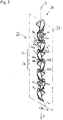
- the formation component 28 is also shown in perspective on its own in Figure 2 shown.
- the spatial proximity of the flow formation 26 to the outlet opening 20 in Figure 1 is preferred.
- the flow formation 26 can actually be arranged at any point in the line 14. Furthermore, between the line 14 and the outlet formation 16 further, in Figure 1 lines not shown be interposed.
- the line 14 which is also shown as a straight line 14 for the sake of simplicity, extends along a line path L, which is imagined to centrally penetrate the conduit cavity 30 through which the flow can flow Formation path F, along which the flow formation 26 and the formation component 28 extend (see also Figure 2 ).
- the flow formation 26, like the line 14, is flexible and can be bent about any bending axes. In particular, it can be rolled up into a helix and the like to save space.
- the flow formation 26 serves as a turbulence flow section 32 of the line 14 along its extension area in order to cause at least in this turbulence flow section 32 a turbulence which separates the cell agglomerations in the cell suspension flowing through it.
- the flow formation 26 has a plurality of formation axial sections arranged axially one behind the other, of which only the formation axial sections 34 and 36 are explained in more detail below, which are arranged alternately in the axial direction in the flow formation 26.
- the conduction path L as well as the formation path F define an axial direction A. They also define a radial direction R which is orthogonal to the axial direction and a circumferential direction U surrounding the respective paths L and F, respectively.
- the natural sense of direction of the axial direction A is directed away from the cell culture container 12.
- the natural sense of direction of the radial direction R is from the Web L or F directed away and the natural direction of the circumferential direction is counterclockwise when viewed in the natural axial direction.
- the formation axial sections 34 and 36 alternating one after the other in the axial direction A serve to accelerate a cell suspension axially flowing through the turbulence flow section 32 in opposite directions in the circumferential direction U.
- the cutting plane SE along which the flow formation 26 or the formation component 28 in Figure 1 section is shown in Figure 2 shown in dash-dotted lines.
- the cutting plane SE contains the formation path F.
- the formation axial sections 34 are designed to accelerate a cell suspension flowing through the conduit 14 or the flow formation 26 in the natural axial direction A in the circumferential direction U in the natural sense of direction, i.e. counterclockwise when viewed in the natural axial direction.
- the formation axial sections 36 are designed to accelerate the cell suspension flowing axially through them in the opposite direction in the circumferential direction, that is to say clockwise when viewed in the natural direction of the axial direction A.
- both the formation axial sections 34 and the formation axial sections 36 have guide surfaces 40a and 40b, respectively.
- the guide surfaces 40a and 40b which each extend radially outward starting from the formation path F, run helically with mutually opposite screwing directions.
- both the formation axial sections 34 and the formation axial sections 36 each have a second guide surface in addition to the guide surface 40a or 40b, which, however, in FIG Figure 2 is always turned away from the viewer.
- the two guide surfaces of each formation axial section 34 or 36 are constructed symmetrically to one another that they can be converted into one another by rotating around the formation path F, in the example shown in each case by rotating through 180 °.
- guide surfaces 40a and 40b therefore also applies to the respective second guide surface of the same formation axial section 34 and 36, respectively Figure 1 a part of the second guide surface 42a of the formation axial sections 34 can be seen.
- the helical guide surfaces 40a, 42a and 40b as well as the non-recognizable further guide surface of the formation axial section 36 have a constant pitch angle ⁇ over their axial extent, the amount of which is the same for both formation axial sections 34 and 36 and only points in opposite directions.
- the helical guide surface 40a thus has a normal vector N, which has an axial component Na, which points axially in the direction from which the flow against the guide surface, and has a component Nu, which points in the circumferential direction in the direction in which the the guide surface 40a impinging flow is accelerated.
- the guide surfaces 40b also have normal vectors M, the axial component Ma of which is of the same magnitude and direction with respect to the axial component Na of the normal vector N of the guide surface 40a. Furthermore, the circumferential direction component Mu of the normal vector M of the guide surface 40b has the same amount, but is directed in the opposite direction to the circumferential direction component Nu of the normal vector N of the guide surface 40a. As a result, the acceleration of the cell suspension flowing through the formation axial sections 34 and 36 in opposite directions in the circumferential direction U is achieved.
- the guide surfaces of one and the same formation axial section each extend in the circumferential direction by 180 ° and thus form half a screw base turn.
- the two guide surfaces of one and the same formation axial section are arranged offset from one another by 180 ° in the circumferential direction, they form both a straight edge 44a, which is orthogonal to the formation path F, axially inflow-side edge 44a for the formation axial sections 34 and 44b for the formation axial sections 36, as well as a straight line to Formation trajectory F orthogonal axially downstream Edge 46a for formation axial sections 34 and 46b for formation axial sections 36.
- the axially inflow-side edges 44a and 44b of a first formation axial section 34 or 36 with respect to the axially outflow-side are preferably Edges 46b or 46a axially of a second formation axial section 36 or 34 immediately preceding the first formation axial section 34 or 36 rotated by 90 ° with respect to one another.
- This cross-wise arrangement of the axially successive formation axial sections 34 and 36 is possible without loss of stability of the formation component 28, since the formation component 28 is stabilized by a central support structure or core 48, which in the present example extends over the entire axial length of the flow formation 26 or the formation component 28 extends.
- a feed pump for generating a cell suspension stream flowing axially through the line 14 away from the cell culture container 12 may be present.
- a pump is not absolutely necessary.
- a flow of cell suspension through the line 14 past the flow formation 26 can be induced by gravity.
- the flow can be generated by generating an overpressure in a gas bubble in the cell culture container 12, so that the gas overpressure in the cell culture container 12 drives the cell suspension out of the container 12 via the outlet opening 20 through the line 14.
- the turbulence flow section 32 can be axially lengthened by arranging several flow formations 26 or several formation components 28 one behind the other in a line 14, thereby lengthening the turbulence path through which the cell suspension passes.
- the formation component 28 can be axially secured in position in the line 14 in a form-fitting manner, for example by an interaction of projections and recesses, and / or cohesively, for example by adhesive.
- a frictional connection between the inner wall of the line 14 and the outer edge of the formation component 28 is sufficient to prevent an axial displacement of the formation component 28 relative to the line 14 when the flow passes through the line 14.
- the line carrying the cell suspension should always be thought of as a straight line along a straight line path, although this is not technically necessary in reality.
Landscapes
- Life Sciences & Earth Sciences (AREA)
- Engineering & Computer Science (AREA)
- Health & Medical Sciences (AREA)
- Chemical & Material Sciences (AREA)
- Wood Science & Technology (AREA)
- Biotechnology (AREA)
- Bioinformatics & Cheminformatics (AREA)
- Organic Chemistry (AREA)
- Zoology (AREA)
- Biomedical Technology (AREA)
- Sustainable Development (AREA)
- Microbiology (AREA)
- Cell Biology (AREA)
- Biochemistry (AREA)
- General Engineering & Computer Science (AREA)
- General Health & Medical Sciences (AREA)
- Genetics & Genomics (AREA)
- Molecular Biology (AREA)
- Apparatus Associated With Microorganisms And Enzymes (AREA)
Description
- Die vorliegende Erfindung betrifft eine Zellvereinzelungsvorrichtung gemäß dem Oberbegriff von Anspruch 1.
- Die vorliegende Erfindung betrifft weiter eine Verwendung einer Strömungsformation zur Vereinzelung von lebenden Zellen in einer Zellsuspension.
- Eine gattungsgemäße Zellvereinzelungsvorrichtung ist aus der
WO 2008/067044 A bekannt. - Grundsätzlich besteht bei Zellkulturen das Problem, dass die nach ihrer Ernte in einer Zellsuspension vorliegenden kultivierten Zellen häufig nicht vollständig vereinzelt vorliegen, sondern zum Teil als Zellcluster oder Zellagglomerationen, in denen mehrere Zellen miteinander verbunden sind.
- Diese Zellagglomerationen sind nachteilig, da die darin verbundenen Zellen sich gegenseitig bedecken, so dass eine agglomerierte Zelle - je nach Anzahl der mit ihr verbundenen Zellen - eine unterschiedlich große von der Flüssigkeit der Zellsuspension benetzbare Oberfläche aufweist. Da Zellen Nährstoffe durch die Membran ihrer Zellhülle aufnehmen, haben die Zellen einer Zellagglomeration unterschiedlich guten Zugang zu in der Suspensionsflüssigkeit enthaltenen Nährstoffen. Weiter wird häufig durch den Kontakt der Zellen untereinander das Zellwachstum der miteinander verbundenen Zellen einschränkt, und zwar umso mehr, je größer die Anzahl an kontaktierenden Nachbarzellen einer Zelle ist.
- Somit führen Zellcluster oder Zellagglomerationen in Zellsuspensionen aufgrund der dargestellten Mechanismen zu unterschiedlich entwickelten Zellen in der Zellkultur, wobei die Zellagglomerationen in der Regel die Ergiebigkeit der Zellkultur nachteilig beeinflussen. Außerdem steigt die Zellsterblichkeit in Zellagglomerationen, verglichen mit der Zellsterblichkeit von Einzelzellen.
- Aus der gattungsgemäßen
WO 2008/067044 A ist eine Zellsuspension führende Leitung mit einem Turbulenz-Strömungsabschnitt bekannt, welcher durch Strömungshindernisse in der Leitung gebildet ist. Dabei sind zwei Strömungshindernisse in Strömungsrichtung mit Abstand voneinander angeordnet, die zueinander versetzte durchströmbare Lochmuster aufweisen. - Bei der Durchströmung der beiden Lochmuster in den die Strömungsformation des Standes der Technik bildenden Strömungshindernissen wird ein Turbulenzgrad in der strömenden Zellsuspension erzielt, bei welchem Zellagglomerationen aufgelöst und die agglomerierten Zellen vereinzelt werden.
- Nachteilig an der bekannten Strömungsformation der gattungsgemäßen Zellvereinzelungsvorrichtung ist ihr geringer Durchlassquerschnitt, denn zur Erzielung des gewünschten Turbulenzgrads weisen die bekannten Strömungshindernisse in dem am wenigsten obstruktiven Fall nur 50 % des Strömungsquerschnitts der die Zellsuspension führenden Leitung ohne Strömungsformation auf. Das Lochmuster der bekannten Strömungshindernisse kann so weit verengt werden, dass der Durchlassquerschnitt der Strömungshindernisse nur noch 1 % des Strömungsquerschnitts der strömungsführenden Leitung ohne Strömungsformation beträgt.
- Eine Vorrichtung zur Zählung von Zellen in einer Zellsuspension mit allen Merkmalen des Oberbegriffs von Anspruch 1 ist aus der
DE 10 2013 200 927 A1 bekannt. - Es ist daher Aufgabe der vorliegenden Erfindung, eine technische Lehre anzugeben, welche bei wenigstens gleichem Vereinzelungserfolg und bei gleichem durchströmbaren Leitungsquerschnitt ohne Strömungsformation einen höheren Mengendurchsatz pro Zeiteinheit gestattet, was nachvollziehbarerweise die Wirtschaftlichkeit der Zellvereinzelungsvorrichtung erhöht.
- Diese Aufgabe wird erfindungsgemäß durch eine Zellvereinzelungsvorrichtung mit allen Merkmalen des Anspruchs 1 gelöst. In einer solchen Vorrichtung weist die Strömungsformation wenigstens zwei axial hintereinander gelegene Formationsaxialabschnitte auf, von welchen der eine dazu ausgebildet ist, eine die Leitung axial von dem nachfolgend nur als "Behälter" bezeichneten Zellkulturbehälter weg durchströmende Zellsuspension in einem ersten Richtungssinn in Umfangsrichtung zu beschleunigen, und von welchen der jeweils andere dazu ausgebildet ist, die Zellsuspension in einem dem ersten Richtungssinn entgegengesetzten zweiten Richtungssinn in Umfangsrichtung zu beschleunigen.
- Gemäß einem weiteren, mit dem vorgenannten durch eine gemeinsame erfinderische Idee verbundenen Erfindungsgedanken wird diese Aufgabe auch gelöst durch die Verwendung einer Strömungsformation mit allen Merkmalen des Anspruchs 11. Gemäß dieser Verwendung erstreckt sich die Strömungsformation längs einer die Strömungsformation zentral durchsetzend gedachten Formationsbahn, wobei die Formationsbahn eine längs der Formationsbahn verlaufende axiale Richtung, eine zur Formationsbahn orthogonale radiale Richtung und eine um die Formationsbahn umlaufende Umfangsrichtung definiert, wobei die Strömungsformation wenigstens zwei axial hintereinander gelegene Formationsaxialabschnitte aufweist, von denen der eine Formationsaxialabschnitt dazu ausgebildet ist, ein den Formationsaxialabschnitt axial anströmendes Fluid in einem ersten Richtungssinn in Umfangsrichtung zu beschleunigen und von welchen der jeweils andere Formationsaxialabschnitt dazu ausgebildet ist, das Fluid in einem dem ersten Richtungssinn entgegengesetzten zweiten Richtungssinn in Umfangsrichtung zu beschleunigen, zur Vereinzelung von lebenden Zellen in einer Zellsuspension als dem strömenden Fluid.
- Nachfolgend wird hauptsächlich die Zellvereinzelungsvorrichtung erläutert und weitergebildet, wobei Weiterbildungen der Strömungsformation auch als Weiterbildungen der Verwendung der Strömungsformation verstanden werden sollen, mit der Maßgabe, dass der Begriff der "Leitungsbahn" für die Weiterbildung der Verwendungsansprüche durch den Begriff "Formationsbahn" ersetzt sein soll.
- Tatsächlich verlaufen Leitungsbahn und Formationsbahn in der betriebsbereiten Zellvereinzelungsvorrichtung kollinear. Da der Verwendungsanspruch jedoch auf die Verwendung einer Strömungsformation für sich alleine gerichtet ist, wird hier anstelle des leitungsbasierten Koordinatensystems das unmittelbar auf die Strömungsformation bezogene Koordinatensystem der Formationsbahn verwendet.
- Erläuterungen der Zellvereinzelungsvorrichtung, die auf die Leitungswandung bezogen sind, sind im Hinblick auf den Verwendungsanspruch als Erläuterungen zu verstehen, die auf den radial äußeren Rand der Strömungsformation gerichtet sind. Dann, wenn sich die Strömungsformation radial bis zur Leitungswand erstreckt, bezeichnet die Radialkoordinate "radial äußerster Rand" der Strömungsformation den gleichen radialen Ort wie die Radialkoordinate "Leitungswand".
- Bei der Beschreibung der Zellvereinzelungsvorrichtung unter Umständen genannte Richtungszusätze zur axialen Richtung, etwa zu dem dem Behälter näheren Längsende der Leitung hin oder von dem Behälter weg, sollen für die Verwendung der Strömungsformation unbeachtlich sein. Hier kommt es lediglich auf die durch die Formationsbahn definierte axiale Richtung an, unabhängig von den zwei konkret möglichen axialen Richtungssinnen.
- Der Grund für diese Begriffszuordnung zwischen den zur Beschreibung der erfindungsgemäßen Zellvereinzelungsvorrichtung verwendeten Begriffen und dem diesen Begriffen für die Weiterbildung der Verwendung der Strömungsformation zu Grunde zu legenden Verständnis liegt darin, dass die Strömungsformation nicht nur integral mit der jeweiligen Leitung ausgebildet sein muss, sondern auch als gesondertes Formationsbauteil unabhängig von der Leitung vorliegen kann, sodass im letztgenannten Fall das zur Beschreibung der Zellvereinzelungsvorrichtung vorteilhafte leitungsbasierte Koordinatensystem nicht anwendbar ist.
- Die Grundidee der vorliegenden Erfindung liegt darin, die axiale Strömung in der Leitung durch die axial hintereinander gelegenen Formationsaxialabschnitte zusätzlich zur axialen Bewegung in entgegengesetzte Umfangsbewegungen zu beschleunigen. Eine Lochblende, wie sie der gattungsgemäße Stand der Technik verwendet, kann dadurch entfallen. Somit kann ein ausreichender Turbulenzgrad ohne die für die Lochblende des Standes der Technik typischen Querschnittsverengungen des Strömungsquerschnitts erreicht werden.
- Zwar erreicht die Zellvereinzelungsvorrichtung des Standes der Technik den Turbulenzgrad durch zwei axial aufeinanderfolgende Lochblenden auf axial sehr kurzem Raum, jedoch ist der zwischen Behälter und dem behälterfernen Leitungsende der Leitung zur Verfügung stehende Anordnungsraum in der Regel nicht kritisch, insbesondere da die Leitung nicht gestreckt, also mit geradliniger Leitungsbahn, verlaufen muss, sondern zu einer Wendel, Spirale und dgl. gewickelt sein kann. Die erfindungsgemäße Zellvereinzelungsvorrichtung benötigt daher zwar einen längeren axialen Leitungsabschnitt zur Erzielung eines hohen Turbulenzgrads als die gattungsgemäße Vorrichtung des Standes der Technik, jedoch kann dies mit einer Querschnittsverringerung des Strömungsquerschnitts der Leitung, verglichen mit der identischen Leitung ohne Strömungsformation, erreicht werden, die 15 %, vorzugsweise 10 %, des identischen Leitungsquerschnitts ohne Strömungsformation nicht überschreitet. Damit kann pro Zeiteinheit eine wesentlich größere Menge an Zellsuspension verwirbelt und damit die darin enthaltenen Zellen sicher vereinzelt werden. Die axial geringfügig längere Ausgestaltung der Leitung wird daher durch den erheblich erhöhten Mengendurchsatz pro Zeiteinheit mehr als kompensiert.
- Dabei ist daran gedacht, dass axial aufeinanderfolgende Formationsaxialabschnitte dazu ausgebildet sind, die grundsätzlich axial die Leitung durchströmende Zellsuspension in entgegengesetzte Umfangsrichtungen zu beschleunigen. Dadurch wird eine Verwirbelung der Zellsuspension erreicht, die für eine Vereinzelung der darin möglicherweise enthaltenen Zellagglomerate ausreicht. Dies wird außerdem besonders schonend erreicht, was sich vorteilhaft auf die Zellviabilität auswirkt. Viele Zellen sind mechanisch nur schwach belastbar, insbesondere durch in Strömungen häufig auftretende Scherbelastung (Scherspannung). Durch die hier auftretende axial abwechselnde Beschleunigung der Suspensionsströmung in entgegengesetzte Umfangsrichtungen wird ein hoher Turbulenzgrad ohne unerwünscht hohe Scherbelastungen erreicht. Das Vereinzelungsergebnis, beispielsweise bestimmt durch die Anzahl nach Durchgang durch die Strömungsformation in einer vorbestimmten Menge an Zellsuspension enthaltener Zellagglomerate im Vergleich zu deren Anzahl vor Durchgang durch die Strömungsformation, ist hervorragend.
- Die Folge der entgegengesetzt gerichteten Umfangsbeschleunigungen kann sein, dass die Zellsuspension, während sie den Turbulenz-Strömungsabschnitt durchströmt, stets im gleichen Richtungssinn, jedoch mit unterschiedlich hohen Geschwindigkeitsbeträgen in Umfangsrichtung strömt. Aus Gründen eines vorteilhaft höheren Turbulenzgrads ist es jedoch bevorzugt, wenn die wenigstens zwei axial hintereinander gelegenen Formationsaxialabschnitte dazu ausgebildet sind, der sie axial durchströmenden Zellsuspension in einem stromaufwärtigen Formationsaxialabschnitt eine in einem ersten Richtungssinn in Umfangsrichtung verlaufende Strömungskomponente zu verleihen, und in einem stromabwärtigen Formationsaxialabschnitt der Zellsuspension eine in einem dem ersten Richtungssinn entgegengesetzten zweiten Richtungssinn in Umfangsrichtung verlaufende Strömungskomponente zu verleihen. In diesem Falle ändert sich die Strömungskomponente der Zellsuspension in Umfangsrichtung nicht nur in ihrem Betrag, sondern auch in ihrem Richtungssinn.
- Auch für die Verwendung gilt der zur Erzielung eines besonders hohen Turbulenzgrads in der Zellsuspension bevorzugte Anwendungsfall, dass von den wenigstens zwei Formationsaxialabschnitten der eine Formationsaxialabschnitt dazu ausgebildet ist, dem den Formationsaxialabschnitt axial anströmenden Fluid eine in einem ersten Richtungssinn in Umfangsrichtung verlaufende Strömungskomponente zu verleihen, und dass der jeweils andere Formationsaxialabschnitt dazu ausgebildet ist, dem Fluid eine in einem dem ersten Richtungssinn entgegengesetzten zweiten Richtungssinn in Umfangsrichtung verlaufende Strömungskomponente zu verleihen.
- Dabei reicht es aus, wenn das Fluid bzw. die Zellsuspension die Formationsaxialabschnitte auch axial anströmt, also neben der axialen Strömungskomponente noch Strömungskomponenten in andere Strömungsrichtungen: radial oder/und in Umfangsrichtung, aufweist. Die Strömung in der Leitung bzw. durch die Strömungsformation muss an keiner Stelle rein axial sein.
- Das Vereinzelungsergebnis kann bei gleichbleibend hoher Zellviabilität verbessert werden, indem die axiale Länge der Strömungsformation und die Anzahl der während dieser axialen Länge stattfindenden Richtungssinnwechsel der Beschleunigung der Strömung in Umfangsrichtung erhöht wird. Gemäß einer vorteilhaften Weiterbildung der Zellvereinzelungsvorrichtung ist daher vorgesehen, dass die Strömungsformation eine Mehrzahl von axial hintereinander gelegenen Formationsaxialabschnitten aufweist, von welchen jeder einem anderen Formationsaxialabschnitt axial nachfolgende Formationsaxialabschnitt dazu ausgebildet ist, die die Leitung in axialer Richtung von dem Behälter weg durchströmende Zellsuspension in einem Richtungssinn in Umfangsrichtung zu beschleunigen, der dem Richtungssinn der Beschleunigung in Umfangsrichtung im axial unmittelbar vorhergehenden Formationsaxialabschnitt entgegengesetzt ist.
- Ein Formationsaxialabschnitt im Sinne dieser Anmeldung soll dabei immer ein Axialabschnitt der Strömungsformation sein, in welchem die Suspensionsströmung in Umfangsrichtung in einem einheitlichen Richtungssinn beschleunigt wird. Ändert sich der Richtungssinn der Strömungsbeschleunigung in Umfangsrichtung, beginnt ein neuer Formationsaxialabschnitt, der sich axial so lange erstreckt, bis sich der Richtungssinn der Beschleunigung der Suspensionsströmung in Umfangsrichtung erneut umkehrt.
- Wiederum ist aus Gründen eines möglichst hohen erzielbaren Turbulenzgrads bevorzugt, wenn sich durch die Umfangsbeschleunigungen in entgegensetzten Richtungssinnen nicht nur der Betrag der Strömungsgeschwindigkeitskomponente der strömenden Zellsuspension in Umfangsrichtung ändert, sondern der Richtungssinn der Bewegung selbst. Folglich ist es bevorzugt, wenn von der Mehrzahl von axial hintereinander gelegenen Formationsaxialabschnitten jeder einem anderen Formationsaxialabschnitt axial nachfolgende Formationsaxialabschnitt dazu ausgebildet ist, der die Leitung in axialer Richtung von dem Behälter weg durchströmenden Zellsuspension eine in Umfangsrichtung verlaufende Strömungskomponente zu verleihen, deren Umfangsrichtungssinn jenem im axial unmittelbar vorhergehenden Formationsaxialabschnitt entgegengesetzt ist.
- Bevorzugt umfasst die Strömungsformation wenigstens acht Formationsaxialabschnitte.
- Fachleute wissen üblicherweise, wie eine axiale Strömung in einer Leitung mit einer Strömungskomponente in Umfangsrichtung versehen werden kann, also in Umfangsrichtung beschleunigt bzw. abgelenkt werden kann. Zur Erzielung des erfindungsgemäßen Erfolgs ist jede Art der Strömungsbeeinflussung geeignet, die in axial aufeinanderfolgenden Formationsaxialabschnitten die Zellsuspension in entgegengesetzte Richtungssinne in Umfangsrichtung beschleunigt.
- So kann gemäß einer vorteilhaften Weiterbildung der vorliegenden Erfindung konstruktiv die Strömungsformation in wenigstens zwei Formationsaxialabschnitten jeweils wenigstens eine Leitfläche aufweisen, welche derart bezüglich der Leitungsbahn geneigt ist, dass der von der Leitfläche definitionsgemäß weg weisende Normalenvektor der Leitfläche einerseits eine Axialkomponente aufweist, die in axialer Richtung zu dem dem Behälter näheren Längsende der Leitung hin weist, von welchem her die Zellsuspension anströmt, und eine Umfangskomponente aufweist, die in Umfangsrichtung weist. Um die Zellsuspension in axial hintereinandergelegenen Formationsaxialabschnitten in Umfangsrichtung in entgegengesetzte Richtungssinne zu beschleunigen, weisen die Umfangskomponenten der Normalenvektoren von Leitflächen axial hintereinandergelegener Formationsaxialabschnitte in entgegengesetzte Richtungen. Bevorzugt weist die Strömungsformation in mehr als zwei Formationsaxialabschnitten jeweils wenigstens eine derartige Leitfläche auf, besonders bevorzugt in jedem ihrer Formationsaxialabschnitte.
- Die Leitfläche kann in einem besonders einfachen Fall eine ebene Fläche sein, welche bezüglich der Leitungsbahn um eine in radiale Richtung verlaufende Anstellachse um einen Anstellwinkel angestellt sein kann. Die Anstellachse kann, muss jedoch nicht, die Leitungsbahn schneiden, sondern kann auch mit Abstand zu dieser verlaufen.
- Zusätzlich kann die Leitfläche, insbesondere in dem diskutierten Fall einer ebenen Fläche als Leitfläche, um eine zur Leitungsbahn parallele Drehachse verdreht sein, insbesondere derart, dass der Normalenvektor der Leitfläche auch eine Komponente nach radial innen auf die Leitungsbahn zu aufweist.
- Der Anstellwinkel der Leitfläche ist wenigstens am axialen Einströmende eines Formationsaxialabschnitts nicht größer als 45° bezüglich einer die Leitungsbahn enthaltenden Ebene am selben Ort, um den Staudruck am Einströmende eines Formationsaxialabschnitts nicht unnötig zu erhöhen.
- Der Anstellwinkel einer Leitfläche in einem Formationsaxialabschnitt kann mit zunehmendem axialen Abstand von dem axialen Einströmende größer werden, sodass die Strömungskomponente in Umfangsrichtung mit zunehmendem axialen Abstand vom Einströmende in dem betreffenden Formationsaxialabschnitt immer größer wird. Die Leitfläche kann dann aus einer Mehrzahl von ebenen Flächenabschnitten gebildet sein, von welchen je zwei in Umfangsrichtung unmittelbar aufeinanderfolgende zueinander abgewinkelt sind. Der Anstellwinkel kann jedoch auch über die axiale Länge eines Formationsaxialabschnitts oder auch über die axiale Länge der gesamten Strömungsformation über alle Leitflächen kontant sein.
- Grundsätzlich kann sich die Leitfläche eines Formationsaxialabschnitts ausgehend von einer den Strömungsbereich der Leitung nach radial außen begrenzenden Leitungswand nach radial innen über die Leitungsbahn hinaus erstrecken. Für eine besonders effektive Ablenkung der Suspensionsströmung in Umfangsrichtung ist es jedoch vorteilhaft, wenn wenigstens ein Formationsaxialabschnitt der Strömungsformation wenigstens zwei Leitflächen aufweist. Die beiden Leitflächen sind dann jeweils im selben Axialbereich der Leitung jeweils in einem Radialbereich zwischen Leitungsbahn und Leitungswand, aber in unterschiedlichen Umfangsbereichen angeordnet. Bevorzugt ist eine Mehrzahl von Formationsaxialabschnitten derart ausgebildet, besonders bevorzugt jeder Formationsaxialabschnitt der Strömungsformation.
- Um eine in einem Formationsaxialabschnitt möglichst homogene Strömung auszubilden, sind die zwei oder mehr Leitflächen eines Formationsaxialabschnitts bevorzugt bezogen auf die Leitungsbahn derart symmetrisch ausgebildet, dass die eine Leitfläche durch Rotation um die Leitungsbahn in eine jeweils andere Leitfläche desselben Formationsaxialabschnitts überführbar ist.
- Dabei gilt: Je mehr Leitflächen in einem Formationsaxialabschnitt in unterschiedlichen Umfangsabschnitten vorgesehen sind, desto sicherer ist einerseits die Beschleunigung der Zellsuspension in Umfangsrichtung, desto größer ist andererseits jedoch auch die Abnahme des durchströmbaren Leitungsquerschnitts, da die Leitflächen als körperliche Gestalten Volumen in dem Leitungsabschnitt beanspruchen, in dem sie angeordnet sind. Bevorzugt sind dabei pro Formationsaxialabschnitt genau zwei oder drei Leitflächen angeordnet, zueinander in Umfangsrichtung versetzt, bevorzugt um 180° (zwei Leitflächen) oder 120° (drei Leitflächen) äquidistant versetzt.
- Zur möglichst sanften und damit scherbelastungsarmen Beschleunigung der Zellsuspensionsströmung in Umfangsrichtung kann die wenigstens eine Leitfläche eines Formationsaxialabschnitts wendelförmig ausgebildet sein. Bevorzugt sind alle Leitflächen eines Formationsaxialabschnitts, besonders bevorzugt aller Formationsaxialabschnitte, wendelförmig ausgebildet.
- Der Steigungswinkel der wendelförmigen Leitfläche ist durch eine Tangentenebene an die aufgrund ihrer wendelförmigen Ausbildung gekrümmte Leitfläche definiert. Wiederum kann der Steigungswinkel mit größer werdendem axialem Abstand vom axialen Einströmende des Formationsaxialabschnitts zum axialen Ausströmende hin zunehmen. Bevorzugt ist der Steigungswinkel über die gesamte axiale Länge der Leitfläche jedoch konstant. Dann, wenn ein Formationsaxialabschnitt mehr als eine Leitfläche aufweist, sind bevorzugt die Steigungswinkel aller Leitflächen an derselben Axialposition gleich. Vorzugsweise sind die Steigungswinkel einer Leitfläche, insbesondere aller Leitflächen, über die gesamte axiale Länge eines Formationsaxialabschnitts konstant. Bevorzugt sind die Steigungswinkel aller Leitflächen aller Formationsaxialabschnitte betragsmäßig konstant und gleich groß und unterscheiden sich zwischen den unterschiedlichen Formationsaxialabschnitten nur durch ihr unterschiedliches Vorzeichen, um aufgrund ihrer unterschiedlichen Neigung die Beschleunigung der Suspensionsströmung in entgegengesetzte Richtungssinne in Umfangsrichtung leisten zu können.
- Grundsätzlich kann die wendelförmige Leitfläche eines Formationsaxialabschnitts die zentral gedachte Leitungsbahn bzw. Formationsbahn beliebig oft umrunden. Für eine besonders effektive und damit wirtschaftliche Strömungsformation ist es jedoch ausreichend und vorteilhaft, wenn die wendelförmige Leitfläche sich längs ihrer Axialerstreckung gerade so weit in Umfangsrichtung um die Leitungsbahn herum erstreckt, dass der sie entlangströmenden Suspension eine eindeutige Beschleunigung oder sogar Bewegung in Umfangsrichtung erteilt wird, bevor die Strömung in den axial nachfolgenden Formationsaxialabschnitt einströmt und dort im entgegengesetzten Richtungssinn in Umfangsrichtung beschleunigt oder sogar bewegt wird. Die Beschleunigung eines Teils der gesamten Zellsuspensionsströmung in Umfangsrichtung reicht dabei aus, etwa 60 % des Massenstroms oder mehr. Versuche haben gezeigt, dass es dabei ausreicht, wenn die wendelförmige Leitfläche längs ihrer axialen Erstreckung wenigstens, vorzugsweise genau, einen Winkel von 180° um die Leitungsbahn überstreicht. Dies gilt bevorzugt für alle Leiflächen ein und desselben Formationsaxialabschnitts. Eine besonders verlustarme Strömung axial durch die Leitung bzw. entlang der Strömungsformation kann bei einer axialen Abfolge von in entgegengesetztem Richtungssinn in Umfangsrichtung beschleunigend wirkenden Formationsaxialabschnitten dadurch erreicht werden, dass der axial einströmseitige Rand einer Leitfläche eines Formationsaxialabschnitts bezüglich des axial ausströmseitigen Randes einer Leitfläche des unmittelbar vorhergehenden (stromaufwärtigen) Formationsaxialabschnitts in Umfangsrichtung versetzt angeordnet ist, vorzugsweise 90° oder 180° versetzt angeordnet ist. Es kann natürlich auch daran gedacht sein, dass die Leitflächen unterschiedlicher axial aufeinanderfolgender Formationsaxialabschnitte randfrei ineinander übergehend verlaufen, wobei dann jedoch bei gleicher axialer Länge der Strömungsanordnung ein weniger starker Turbulenzgrad erreicht wird, was für besonders empfindliche Zellen vorteilhaft sein kann. Die kontinuierliche randfreie Ausbildung einer einzigen Leitstruktur mit unterschiedlichen Leitflächenabschnitten, die den jeweiligen Formationsaxialabschnitten zugeordnet sind, soll jedoch von der vorliegenden Anmeldung nicht ausgeschlossen sein. Grundsätzlich kann weiter daran gedacht sein, die Strömungsformation einstückig mit der Leitung auszubilden, etwa indem die Leitung durch vergleichsweise weichelastischen Silikonkunststoff gebildet ist. Derartiger Silikonkunststoff gestattet nach dem Aushärten eine zerstörungsfreie Entformung eines die Strömungsformation radial innen in der Leitung bildenden Formkerns in axialer Richtung, in welcher die Leitung schließlich auch von der Zellsuspension im Betrieb durchströmt wird. Beispielsweise können die Leitflächen der Formationsaxialabschnitte bei einstückiger Ausbildung der Strömungsformation mit der Leitung von der Leitungswand nach radial innen vorstehen, wobei sie nicht notwendigerweise nach radial innen bis zur Leitungsmitte, also bis zum Ort der virtuellen Leitungsbahn, verlaufen müssen.
- Bevorzugt ist die Strömungsformation jedoch an einem von der Leitung gesondert ausgebildeten Formationsbauteil ausgebildet. Dies hat zum einen fertigungstechnische Vorteile, denn ein solches Formationsbauteil kann als gesondertes Bauteil wesentlich einfacher und kostengünstiger mit größerem konstruktiven Freiheitsgrad hergestellt werden als eine einstückig sich radial innerhalb der Leitung erstreckende Strömungsformation.
- Ein geeignetes Formationsbauteil ist als Mischerbauteil zur effektiven Vermischung von zwei Komponenten eines Mischerzeugnisses aus der
DE 20 2012 002 102 U1 bekannt. Während das Formationsbauteil in der genannten Druckschrift zum Mischen unterschiedlicher flüssiger Komponenten verwendet wird, wird es gemäß der vorliegenden Erfindung zur Trennung von Zellagglomerationen in einer Flüssigkeit verwendet. - Ein weiterer Vorteil in der gesonderten Ausbildung des Formationsbauteils liegt in der erheblich verbesserten Möglichkeit, Leitung und Strömungsformation nach Gebrauch zu reinigen und gegebenenfalls zu sterilisieren, um Leitung und Strömungsbauteil erneut für eine andere Zellsuspension einsetzen zu können, ohne eine Kontamination der Zellsuspension durch die Leitung und die Strömungsformation aufgrund des vorherigen Einsatzes befürchten zu müssen.
- Um die Leitung bei vorgegebener Axial-Strömungsgeschwindigkeitskomponente mit langer Verwirbelungsdauer und damit wiederum hohem Vereinzelungserfolg bei gleichzeitig hoher Zellviabilität mit Zellsuspension durchströmen zu können zu können, ist das Formationsbauteil bevorzugt verformbar, sodass es auch in eine baulich lange, nicht geradlinig verlaufende Leitung einsetzbar ist. Bevorzugt ist die Leitung zur Erzielung einer möglichst langen axialen Verwirbelungsstrecke wendelförmig aufgerollt, sodass es für das Formationsbauteil besonders vorteilhaft ist, wenn es biegsam ist, insbesondere um eine oder mehrere mit der Leitungsbahn einen Winkel einschließende Biegeachsen. Der Winkel der Biegeachsen mit der Leitungsbahn ist dabei vorzugsweise ein rechter Winkel.
- Bevorzugt ist auch die Leitung verformbar, sodass sie je nach Anwendungsfall in eine geeignete Form gebracht werden kann, jeweils im Rahmen ihrer Verformbarkeit.
- Bevorzugt ist das Formationsbauteil als Spritzgussbauteil hergestellt, wobei dann vorteilhafterweise die Verformbarkeit durch die Materialdicke der die Leitflächen aufweisenden Leitstruktur einstellbar ist.
- Zur Stabilisierung der Strömungsformation, insbesondere des Formationsbauteils, kann diese eine sich wenigstens längs eines Axialabschnitts der Strömungsformation, vorzugsweise sich axial längs der gesamten Strömungsformation erstreckende Tragstruktur aufweisen, mit welcher die Leitflächen an ihrem radial inneren Ende verbunden sind, vorzugsweise einstückig verbunden sind. Die Tragstruktur ist vorzugsweise eine zentrale Stab- oder Säulenstruktur, mithin eine Seele des Formationsbauteils, deren radiale Abmessung zur Vermeidung unnötiger Strömungshindernisse bevorzugt kleiner ist als die radiale Abmessung der Strömungsformation insgesamt.
- Die Zellvereinzelung mit der erfindungsgemäßen Vorrichtung kann vorteilhaft in einem vollständig geschlossenen System erfolgen, ohne dass die Zellsuspension mit der Atmosphäre in Kontakt gelangt. Am stromabwärtigen Ende der Leitung kann ein Auffangbehälter angeordnet sein, in welchen die Zellsuspension mit den vereinzelten Zellen gefördert wird.
- Die vorliegende Erfindung wird nachfolgend anhand der beiliegenden Zeichnungen näher erläutert. Es stellt dar:
- Figur 1
- eine grobschematische Darstellung durch eine erfindungsgemäße Ausführungsform einer Zellvereinzelungsvorrichtung der vorliegenden Anmeldung im Längsschnitt und
- Figur 2
- eine perspektivische Ansicht des in der Zellvereinzelungsvorrichtung von
Figur 1 verwendeten Formationsbauteils. - In
Figur 1 ist eine erfindungsgemäße Ausführungsform einer Zellvereinzelungsvorrichtung der vorliegenden Anmeldung allgemein mit 10 bezeichnet. Diese umfasst einen Behälter 12, etwa einen Zellkulturbehälter, von welchem in dem grobschematischen Längsschnitt vonFigur 1 lediglich ein Eckbereich dargestellt ist. - An den Behälter 12 schließt eine Leitung 14 an, etwa eine flexible Schlauchleitung 14.
- Die Schlauchleitung 14 ist an eine Auslassformation 16 des Zellkulturbehälters 12 gekoppelt und dort mittels einer Schraubsicherung 18 positionsgesichert, insbesondere gegen einen Auszug aus der Auslassformation 16.
- Die Auslassformation 16 ist in
Figur 1 lediglich grobschematisch dargestellt. Im dargestellten Beispiel ist die Leitung 14 mit der Auslassformation 16 dauerhaft gekoppelt. Dies muss nicht so sein. Die Leitung 14 kann auch über an sich bekannte Anschluss- bzw. Kopplungsformationen steckbar und somit schnell verbindbar und lösbar mit der Auslassformation 16 koppelbar sein. Zumindest kann eine solche steckbare Verbindung schneller hergestellt und wieder gelöst werden, als dies durch die Schraubsicherung 18 der Fall ist. Auf die Art und Weise der Strömungsverbindung der Leitung 14 mit einer von der Auslassformation 16 umgebenen Auslassöffnung 20 des Zellkulturbehälters 12 kommt es jedoch vorliegend nicht an. - In dem strichliniert umfassten Bereich 24 in der Anschlussformation 16 und ebenso in der Leitung 14 kann eine in an sich bekannter Weise wirkende Ventilanordnung 24 angeordnet sein, über die eine Strömungsverbindung der Leitung 14 mit der Auslassöffnung 20 wahlweise herstellbar oder sperrbar ist. Die Ventilanordnung 24 kann in an sich bekannter Weise berührungslos durch Magnetfeldmanipulation von außerhalb der Auslassformation 16 schaltbar sein, beispielsweise durch Änderung eines von außerhalb der Auslassformation 16 auf die Ventilanordnung 24 einwirkenden Magnetfelds, wodurch ein ferromagnetischer Ventilkörper zwischen einer Durchlassstellung und einer Sperrstellung verlagerbar sein kann.
- Der Zellkulturbehälter 12 dient im vorliegenden Beispiel der Kultivierung adhärenter Zellen, die zunächst an einer Kulturfläche im Zellkulturbehälter 12 anhaftend wachsen und sich nach Zugabe eines entsprechenden Lösemittels in die im Zellbehälter 12 vorhandene Flüssigkeit von ihren Kulturflächen lösen, sodass die Zellen dann frei in der Flüssigkeit im Zellkulturbehälter 12 schweben und somit mit der Flüssigkeit im Zellkulturbehälter 12 eine Zellsuspension bilden. Die in der Zellsuspension gelösten Zellen sind erntereif und werden üblicherweise kurz nach dem Lösen von ihren Kulturflächen aus dem Zellkulturbehälter 12 entnommen, im vorliegenden Beispiel durch die Auslassöffnung 20.
- Dabei passiert es in der Regel, dass die Zellen nicht völlig vereinzelt in der Flüssigkeit im Zellkulturbehälter 12 aufgenommen sind, sondern darin Zellagglomerationen aus einer unterschiedlichen Anzahl aneinander anhaftender Zellen bilden. Gewünscht sind jedoch vereinzelte Zellen, da die Zellagglomerationen, wie in der Beschreibungseinleitung dieser Anmeldung geschildert, sich überwiegend nachteilig auf die Entwicklung und die Weiterverarbeitbarkeit der kultivierten Zellen auswirken.
- Zum Zwecke der Vereinzelung der Zellen aus den unerwünschten Zellagglomerationen ist in der Leitung 14 eine Strömungsformation 26 angeordnet, im dargestellten Beispiel ausgebildet durch ein gesondert von der Leitung 14 ausgebildetes und in dieser angeordnetes Formationsbauteil 28. Das Formationsbauteil 28 ist in Alleinstellung perspektivisch auch in
Figur 2 dargestellt. - Die räumliche Nähe der Strömungsformation 26 zur Auslassöffnung 20 in
Figur 1 ist bevorzugt. Die Strömungsformation 26 kann tatsächlich an einer beliebigen Stelle in der Leitung 14 angeordnet sein. Weiterhin können zwischen der Leitung 14 und der Auslassformation 16 weitere, inFigur 1 nicht dargestellte Leitungen zwischenangeordnet sein. - Die Leitung 14, die ebenfalls der Einfachheit halber als geradlinige Leitung 14 dargestellt ist, erstreckt sich längs einer den durchströmbaren Leitungshohlraum 30 zentral durchsetzend gedachten Leitungsbahn L. Da die Strömungsformation 26 in der Leitung 14 kollinear mit dieser angeordnet ist, ist die Leitungsbahn L zugleich auch Formationsbahn F, längs welcher sich die Strömungsformation 26 sowie das Formationsbauteil 28 erstrecken (siehe auch
Figur 2 ). - Die Strömungsformation 26 ist ebenso wie die Leitung 14 flexibel und kann um beliebige Biegeachsen gebogen werden. Sie kann insbesondere raumsparend zu einer Wendel und ähnlichem aufgerollt werden.
- Die Strömungsformation 26 dient vorliegend längs ihres Erstreckungsbereichs als Turbulenz-Strömungsabschnitt 32 der Leitung 14, um wenigstens in diesem Turbulenz-Strömungsabschnitt 32 eine die Zellagglomerationen in der sie durchströmenden Zellsuspension vereinzelnde Verwirbelung zu bewirken.
- Hierzu weist die Strömungsformation 26 mehrere axial hintereinander angeordnete Formationsaxialabschnitte auf, von denen nachfolgend lediglich die Formationsaxialabschnitte 34 und 36 näher erläutert werden, die in axialer Richtung in der Strömungsformation 26 alternierend angeordnet sind.
- Die Leitungsbahn L ebenso wie die Formationsbahn F definieren eine axiale Richtung A. Sie definieren außerdem eine zur axialen Richtung orthogonale radiale Richtung R sowie eine die jeweiligen Bahnen L bzw. F umgebende Umfangsrichtung U.
- Der natürliche Richtungssinn der axialen Richtung A ist von dem Zellkulturbehälter 12 weg gerichtet. Der natürliche Richtungssinn der radialen Richtung R ist von der Bahn L bzw. F weg gerichtet und der natürliche Richtungssinn der Umfangsrichtung ist bei Betrachtung in der natürlichen axialen Richtung entgegen dem Uhrzeigersinn.
- Die in axialer Richtung A alternierend aufeinanderfolgenden Formationsaxialabschnitte 34 und 36 dienen dazu, eine den Turbulenz-Strömungsabschnitt 32 axial durchströmende Zellsuspension abwechselnd in entgegengesetzte Richtungssinne in Umfangsrichtung U zu beschleunigen.
- Die Schnittebene SE, längs welcher die Strömungsformation 26 bzw. das Formationsbauteil 28 in
Figur 1 geschnitten dargestellt ist, ist inFigur 2 strichpunktiert dargestellt. Die Schnittebene SE enthält die Formationsbahn F. - Die Formationsaxialabschnitte 34 sind dazu ausgebildet, eine die Leitung 14 bzw. die Strömungsformation 26 in der natürlichen axialen Richtung A durchströmende Zellsuspension in Umfangsrichtung U im Sinne des natürlichen Richtungssinns, also bei Betrachtung in der natürlichen axialen Richtung, im Gegenuhrzeigersinn zu beschleunigen.
- Die Formationsaxialabschnitte 36 sind dagegen dazu ausgebildet, die sie axial durchströmende Zellsuspension im entgegengesetzten Richtungssinn in Umfangsrichtung, also bei Betrachtung im natürlichen Richtungssinn der axialen Richtung A im Uhrzeigersinn, zu beschleunigen. Hierzu weisen sowohl die Formationsaxialabschnitte 34 wie auch die Formationsaxialabschnitte 36 Leitflächen 40a bzw. 40b auf. Die Leitflächen 40a und 40b, welche sich jeweils von der Formationsbahn F ausgehend radial nach außen erstrecken, verlaufen wendelförmig mit einander entgegengesetztem Schraubsinn. Tatsächlich weisen sowohl die Formationsaxialabschnitte 34 wie auch die Formationsaxialabschnitte 36 jeweils eine zweite Leitfläche zusätzlich zur Leitfläche 40a bzw. 40b auf, die jedoch in
Figur 2 stets vom Betrachter abgewandt ist. Die beiden Leitflächen eines jeden Formationsaxialabschnitts 34 oder 36 sind derart symmetrisch zueinander aufgebaut, dass sie durch Drehung um die Formationsbahn F ineinander überführbar sind, im dargestellten Beispiel jeweils durch Drehung um 180°. - Somit gilt die Beschreibung der Leitflächen 40a und 40b auch für die jeweils zweite Leitfläche desselben Formationsaxialabschnitts 34 bzw. 36. Lediglich in
Figur 1 ist ein Teil der zweiten Leitfläche 42a der Formationsaxialabschnitte 34 erkennbar. - Die wendelförmigen Leitflächen 40a, 42a und 40b sowie die nicht erkennbare weitere Leitfläche des Formationsaxialabschnitts 36 weisen über ihre axiale Erstreckung einen konstanten Steigungswinkel α auf, der für beide Formationsaxialabschnitte 34 und 36 betragsmäßig gleich groß und lediglich entgegengesetzt gerichtet ist.
- Die wendelförmige Leitfläche 40a weist somit einen Normalenvektor N auf, der eine Axialkomponente Na aufweist, die axial in die Richtung weist, aus der die Leitfläche angeströmt wird, und weist eine Komponente Nu auf, die in Umfangsrichtung in jenem Richtungssinn weist, in dem die auf die Leitfläche 40a auftreffende Strömung beschleunigt wird.
- Ebenso weisen die Leitflächen 40b Normalenvektoren M auf, deren Axialkomponente Ma betrags- und richtungsgleich bezüglich der Axialkomponente Na des Normalenvektors N der Leitfläche 40a ist. Weiter ist die Umfangsrichtungskomponente Mu des Normalenvektors M der Leitfläche 40b betragsgleich, aber entgegengesetzt gerichtet wie die Umfangsrichtungskomponente Nu des Normalenvektors N der Leitfläche 40a. Dadurch wird die Beschleunigung der die Formationsaxialabschnitte 34 und 36 durchströmenden Zellsuspension in entgegengesetzte Richtungssinne in Umfangsrichtung U erreicht.
- Die Leitflächen ein und desselben Formationsaxialabschnitts erstrecken sich in Umfangsrichtung jeweils um 180° und bilden somit eine halbe Schraubenbasiswindung aus.
- Dadurch, dass die beiden Leitflächen ein und desselben Formationsaxialabschnitts um 180° in Umfangsrichtung zueinander versetzt angeordnet sind, bilden sie sowohl einen geradlinigen zur Formationsbahn F orthogonalen axial einströmseitigen Rand 44a für die Formationsaxialabschnitte 34 und 44b für die Formationsaxialabschnitte 36, als auch einen geradlinigen und zur Formationsbahn F orthogonalen axial ausströmseitigen Rand 46a für die Formationsaxialabschnitte 34 und 46b für die Formationsaxialabschnitte 36.
- Da sich die Leitflächen 40a, 40b und 42a der Formationsaxialabschnitte 34 bzw. 36 längs ihrer Axialerstreckung um 180° in Umfangsrichtung um die Formationsbahn F bzw. Leitungsbahn L winden, sind die axial einströmseitigen und die axial ausströmseitigen Ränder 44a und 46a bzw. 44b und 46b ein und desselben Formationsaxialabschnitts 34 bzw. 36 zueinander parallel.
- Um eine möglichst effektive Verwirbelung der die Leitung 14 mit der Strömungsformation 26 durchströmenden Zellsuspension und damit eine möglichst gründliche Vereinzelung der in der Zellsuspension vorhandenen Zellen zu erreichen, sind vorzugsweise die axial einströmseitigen Ränder 44a bzw. 44b eines ersten Formationsaxialabschnitts 34 oder 36 bezüglich der axial ausströmseitigen Ränder 46b bzw. 46a axial eines dem ersten Formationsaxialabschnitt 34 oder 36 unmittelbar vorausgehenden zweiten Formationsaxialabschnitts 36 oder 34 um 90° zueinander verdreht.
- Diese kreuzweise Anordnung der axial aufeinanderfolgenden Formationsaxialabschnitte 34 und 36 ist ohne Stabilitätsverlust des Formationsbauteils 28 möglich, da das Formationsbauteil 28 durch eine zentrale Tragstruktur bzw. Seele 48 stabilisiert ist, die sich im vorliegenden Beispiel über die gesamte axiale Länge der Strömungsformation 26 bzw. des Formationsbauteils 28 erstreckt.
- In
Figur 1 ist keine Pumpe eingezeichnet, wenngleich eine Förderpumpe zur Erzeugung eines axial die Leitung 14 vom Zellkulturbehälter 12 weg durchströmenden Zellsuspensionsstroms vorhanden sein kann. Allerdings ist eine Pumpe nicht zwingend notwendig. Zusätzlich oder alternativ kann eine Strömung von Zellsuspension durch die Leitung 14 an der Strömungsformation 26 vorbei schwerkraftinduziert sein. Weiter zusätzlich oder alternativ kann die Strömung durch Erzeugung eines Überdrucks in einer Gasblase im Zellkulturbehälter 12 erzeugt werden, sodass der Gasüberdruck im Zellkulturbehälter 12 die Zellsuspension aus dem Behälter 12 über die Auslassöffnung 20 durch die Leitung 14 hindurch austreibt. - Mit der in der vorliegenden Anmeldung beschriebenen Strömungsformation 26 und ihrer Verwendung zur Zellvereinzelung wird ein hervorragendes Vereinzelungsergebnis bei gleichzeitig hoher Zellviabilität erzielt. Je nach "Hartnäckigkeit" der in der Zellsuspension vorhandenen Zellagglomerationen kann der Turbulenz-Strömungsabschnitt 32 durch Hintereinanderanordnung mehrerer Strömungsformationen 26 bzw. mehrerer Formationsbauteile 28 in einer Leitung 14 axial verlängert werden, wodurch die Turbulenzstrecke verlängert wird, die die Zellsuspension durchläuft. So kann durch Anpassung der axialen Länge des Turbulenz-Strömungsabschnitts 32 und durch die Aufwickelbarkeit der Leitung 14 zusammen mit der darin aufgenommenen Strömungsformation 26 jede Zellsuspension ohne großen Bauraumaufwand nahezu vollständig von Zellagglomerationen befreit werden.
- Das Formationsbauteil 28 kann formschlüssig, etwa durch ein Zusammenspiel von Vorsprüngen und Ausnehmungen, oder/und stoffschlüssig, etwa durch Klebstoff, in der Leitung 14 axial positionsgesichert sein. Üblicherweise reicht jedoch bereits ein Reibschluss zwischen der Innenwand der Leitung 14 und dem Außenrand des Formationsbauteils 28 aus, um bei der Durchströmung der Leitung 14 eine axiale Verlagerung des Formationsbauteils 28 relativ zur Leitung 14 zu verhindern. Der Reibschluss ist umso ausreichender, je stärker der Leitung 14 gekrümmt angeordnet ist, etwa in der oben beschriebenen Wendelform zur platzsparenden Anordnung auch längerer Leitungsabschnitte.
- Sofern im Verständnis der vorliegenden Anmeldung Zweifel bestehen, soll die die Zellsuspension führende Leitung immer als geradlinige Leitung entlang einer geradlinigen Leitungsbahn gedacht sein, wenngleich dies in der Realität technisch nicht zwingend erforderlich ist.
Claims (12)
- Zellvereinzelungsvorrichtung (10) zur Vereinzelung lebender Zellen, umfassend einen Zellkulturbehälter (12) zur Aufnahme einer Zellsuspension und eine mit dem Zellkulturbehälter (12) verbundene Leitung (14) zur Durchleitung von Zellsuspension aus dem Zellkulturbehälter (12), wobei sich die Leitung (14) längs einer die Leitung (14) zentral durchsetzend gedachten Leitungsbahn (L) erstreckt, wobei die Leitungsbahn (L) in der Leitung (14) eine längs der Leitungsbahn (L) verlaufende axiale Richtung (A), eine zur Leitungsbahn (L) orthogonale radiale Richtung (R) und eine um die Leitungsbahn (L) umlaufende Umfangsrichtung (U) definiert, wobei wenigstens ein Abschnitt der Leitung (14) als Turbulenz-Strömungsabschnitt (32) eine eine turbulente Zellsuspensionsströmung erzeugende Strömungsformation (26) aufweist,
dadurch gekennzeichnet, dass die Strömungsformation (26) wenigstens zwei axial hintereinander gelegene Formationsaxialabschnitte (34, 36) aufweist, von welchen der eine dazu ausgebildet ist, eine die Leitung (14) axial von dem Zellkulturbehälter (12) weg durchströmende Zellsuspension in einem ersten Richtungssinn in Umfangsrichtung (U) zu beschleunigen, und von welchen der jeweils andere dazu ausgebildet ist, die Zellsuspension in einem dem ersten Richtungssinn entgegengesetzten zweiten Richtungssinn in Umfangsrichtung (U) zu beschleunigen. - Zellvereinzelungsvorrichtung (10) nach Anspruch 1,
dadurch gekennzeichnet, dass die Strömungsformation (26) eine Mehrzahl von axial hintereinander gelegenen Formationsaxialabschnitten (34, 36) aufweist, von welchen jeder einem anderen Formationsaxialabschnitt (34, 36) axial nachfolgende Formationsaxialabschnitt (34, 36) dazu ausgebildet ist, die die Leitung (14) in axialer Richtung (A) von dem Zellkulturbehälter (12) weg durchströmende Zellsuspension in Umfangsrichtung (U) in einem Umfangsrichtungssinn zu beschleunigen, welcher jenem im axial unmittelbar vorhergehenden Formationsaxialabschnitt (36, 34) entgegengesetzt ist. - Zellvereinzelungsvorrichtung (10) nach Anspruch 1 oder 2,
dadurch gekennzeichnet, dass die Strömungsformation (26) in wenigstens zwei Formationsaxialabschnitten (34, 36), vorzugsweise in jedem Formationsaxialabschnitt (34, 36), jeweils wenigstens eine Leitfläche (40a, 42a, 40b) aufweist, welche derart bezüglich der Leitungsbahn (L) geneigt ist, dass der Normalenvektor (N, M) der Leitfläche (40a, 42a, 40b) eine Axialkomponente (Na, Ma) aufweist, die in axialer Richtung (A) zu dem dem Zellkulturbehälter (12) näheren Längsende der Leitung (14) hinweist, und eine Umfangskomponente (Nu, Mu) aufweist, die in Umfangsrichtung (U) weist, wobei die Umfangskomponenten (Nu, Mu) von Leitflächen (40a, 42a, 40b) axial hintereinander gelegener Formationsaxialabschnitte (34, 36) in entgegengesetzte Richtungssinne weisen. - Zellvereinzelungsvorrichtung (10) nach Anspruch 3,
dadurch gekennzeichnet, dass wenigstens ein Formationsaxialabschnitt (34, 36) der Strömungsformation (26), vorzugsweise eine Mehrzahl von Formationsaxialabschnitten (34, 36), besonders bevorzugt jeder Formationsaxialabschnitt (34, 36), jeweils wenigstens zwei Leitflächen (40a, 42a, 40b) aufweist, welche im selben Axialbereich der Leitung (14) in einem Radialbereich zwischen Leitungsbahn (L) und Leitungswand, aber in unterschiedlichen Umfangsbereichen angeordnet sind, wobei bevorzugt die Leitflächen (40a, 42a, 40b) eines Formationsaxialabschnitts (34, 36) bezogen auf die Leitungsbahn (L) derart symmetrisch ausgebildet sind, dass die eine Leitfläche (40a, 42a, 40b) durch Rotation um die Leitungsbahn (L) in eine jeweils andere Leitfläche (40a, 42a, 40b) desselben Formationsaxialabschnitts (34, 36) überführbar ist. - Zellvereinzelungsvorrichtung (10) nach Anspruch 3 oder 4,
dadurch gekennzeichnet, dass die wenigstens eine Leitfläche (40a, 42a, 40b) wendelförmig ausgebildet ist. - Zellvereinzelungsvorrichtung (10) nach Anspruch 5,
dadurch gekennzeichnet, dass die wendelförmige Leitfläche (40a, 42a, 40b) längs ihrer axialen Erstreckung wenigstens, vorzugsweise genau, einen Winkel von 180° um die Leitungsbahn (L) überstreicht. - Zellvereinzelungsvorrichtung (10) nach einem der Ansprüche 3 bis 6,
dadurch gekennzeichnet, dass der axial einströmseitige Rand (44a, 44b) einer Leitfläche (40a, 42a, 40b) eines Formationsaxialabschnitts (34, 36) bezüglich des axial ausströmseitigen Randes (46b, 46a) einer Leitfläche (40a, 42a, 40b) des unmittelbar vorhergehenden Formationsaxialabschnitts (36, 34) in Umfangsrichtung (U) versetzt angeordnet ist, vorzugsweise um 90° oder um 180° versetzt angeordnet ist. - Zellvereinzelungsvorrichtung (10) nach einem der vorhergehenden Ansprüche,
dadurch gekennzeichnet, dass die Strömungsformation (26) an einem von der Leitung (14) gesonderten Formationsbauteil (28) ausgebildet ist. - Zellvereinzelungsvorrichtung (10) nach Anspruch 8,
dadurch gekennzeichnet, dass das Formationsbauteil (28) verformbar ist, insbesondere biegsam ist, besonders bevorzugt um eine oder mehrere mit der Leitungsbahn (L) einen Winkel, vorzugsweise einen rechten Winkel, einschließende Biegeachsen. - Zellvereinzelungsvorrichtung (10) nach einem der vorhergehenden Ansprüche,
dadurch gekennzeichnet, dass der Zellkulturbehälter (12) als Zellkulturbehälter (12) zur Kultivierung adhärenter Zellen eine Kulturfläche aufweist, an welcher die adhärenten Zellen anhaftend wachsen. - Zellvereinzelungsvorrichtung (10) nach einem der vorhergehenden Ansprüche,
dadurch gekennzeichnet, dass die Strömungsformation (26) frei von Lochblenden ist. - Verwendung einer Strömungsformation (26) zur Vereinzelung von lebenden Zellen in einer Zellsuspension als dem strömenden Fluid, welche Strömungsformation (26) sich längs einer die Strömungsformation (26) zentral durchsetzend gedachten Formationsbahn (F) erstreckt, wobei die Formationsbahn (F) eine längs der Formationsbahn (F) verlaufende axiale Richtung (A), eine zur Formationsbahn (F) orthogonale radiale Richtung (R) und eine um die Formationsbahn (F) umlaufende Umfangsrichtung (U) definiert, wobei die Strömungsformation (26) wenigstens zwei axial hintereinander gelegene Formationsaxialabschnitte (34, 36) aufweist, von denen der eine Formationsaxialabschnitt (34, 36) dazu ausgebildet ist, ein den Formationsaxialabschnitt (34, 36) axial anströmendes Fluid in einem ersten Richtungssinn in Umfangsrichtung (U) zu beschleunigen und von welchen der jeweils andere Formationsaxialabschnitt (34, 36) dazu ausgebildet ist, das Fluid in einem dem ersten Richtungssinn entgegengesetzten zweiten Richtungssinn in Umfangsrichtung (U) zu beschleunigen.
Applications Claiming Priority (2)
| Application Number | Priority Date | Filing Date | Title |
|---|---|---|---|
| DE102016202139.7A DE102016202139A1 (de) | 2016-02-12 | 2016-02-12 | Zellvereinzelungsvorrichtung und Verwendung einer Strömungsformation zur Zellvereinzelungsvorrichtung |
| PCT/EP2017/052812 WO2017137472A1 (de) | 2016-02-12 | 2017-02-09 | Zellvereinzelungsvorrichtung und verwendung einer strömungsformation zur zellvereinzelungsvorrichtung |
Publications (2)
| Publication Number | Publication Date |
|---|---|
| EP3414548A1 EP3414548A1 (de) | 2018-12-19 |
| EP3414548B1 true EP3414548B1 (de) | 2020-10-07 |
Family
ID=58054095
Family Applications (1)
| Application Number | Title | Priority Date | Filing Date |
|---|---|---|---|
| EP17705566.2A Active EP3414548B1 (de) | 2016-02-12 | 2017-02-09 | Zellvereinzelungsvorrichtung und verwendung einer strömungsformation zur zellvereinzelungsvorrichtung |
Country Status (4)
| Country | Link |
|---|---|
| US (1) | US11485952B2 (de) |
| EP (1) | EP3414548B1 (de) |
| DE (1) | DE102016202139A1 (de) |
| WO (1) | WO2017137472A1 (de) |
Families Citing this family (5)
| Publication number | Priority date | Publication date | Assignee | Title |
|---|---|---|---|---|
| DE102024121069A1 (de) | 2024-07-24 | 2026-01-29 | Hamilton Bonaduz Ag | Medienbehältersystem für eine Zellkultur-Bewirtschaftungsvorrichtung |
| DE102024121072A1 (de) | 2024-07-24 | 2026-01-29 | Hamilton Bonaduz Ag | Taumelvorrichtung für eine Zellkultur-Bewirtschaftungsvorrichtung zur Benetzung von Oberflächen in einem Zellkulturbehälter |
| DE102024121067A1 (de) | 2024-07-24 | 2026-01-29 | Hamilton Bonaduz Ag | Zellkultur-Bewirtschaftungsvorrichtung mit einer Ventilblockanordnung mit wenigstens zwei gesondert voneinander ausgebildeten Ventilblöcken |
| WO2026022007A1 (de) | 2024-07-24 | 2026-01-29 | Hamilton Bonaduz Ag | Zellkulturbehälter-betriebseinrichtung zur sicheren lösbaren aufnahme eines zellkulturbehälters während einer zellkultur-bewirtschaftung |
| DE102024121070A1 (de) | 2024-07-24 | 2026-01-29 | Hamilton Bonaduz Ag | Zellkultur-Bewirtschaftungsvorrichtung mit Medienförderung zwischen Zellkulturbehältern und Verfahren für einen Medientransfer zwischen Zellkulturbehältern |
Family Cites Families (15)
| Publication number | Priority date | Publication date | Assignee | Title |
|---|---|---|---|---|
| US3794300A (en) * | 1971-12-30 | 1974-02-26 | Dow Badische Co | Annular spiral isg |
| US4840493A (en) * | 1987-11-18 | 1989-06-20 | Horner Terry A | Motionless mixers and baffles |
| US5069881A (en) * | 1990-07-10 | 1991-12-03 | Mobay Corporation | Device and method for applying adhesives |
| DE4435717A1 (de) * | 1994-07-06 | 1996-01-11 | Hennecke Gmbh Maschf | Verfahren zum kontinuierlichen Dispergieren von feinteiligen Feststoffen in einer Flüssigkeit |
| US6840281B1 (en) * | 2001-11-06 | 2005-01-11 | Vent-Matic Company, Inc. | Liquid flow pressure reducer and method |
| US7041218B1 (en) * | 2002-06-10 | 2006-05-09 | Inflowsion, L.L.C. | Static device and method of making |
| US20050106452A1 (en) * | 2003-07-28 | 2005-05-19 | Qureshi Nawaz M. | Acid stripper |
| WO2008019964A1 (de) | 2006-08-15 | 2008-02-21 | Basf Se | Verfahren zur isolierung von proteinen aus produktionszellen |
| EP2076157B1 (de) | 2006-10-11 | 2018-08-01 | Merial, Inc. | Dispersionsvorrichtungen für aggregate |
| US8927287B2 (en) | 2009-10-09 | 2015-01-06 | Georgia Tech Research Corporation | Method for dispersion of assemblies of biological material |
| US9957472B2 (en) * | 2011-09-22 | 2018-05-01 | Georgia Tech Research Corporation | Deterministic high-density single-cell trap array |
| US20130205729A1 (en) * | 2012-02-13 | 2013-08-15 | Nawaz M. Qureshi | Acid Stripper |
| DE202012002102U1 (de) | 2012-03-02 | 2013-06-04 | Udo Tartler | Vorrichtung zum Mischen mindestens zweier fluider Komponenten, drehangetriebener Mischereinsatz dafür und System aus beidem |
| DE102013200927A1 (de) | 2013-01-22 | 2014-07-24 | Siemens Aktiengesellschaft | Verfahren zum Anreichern und Vereinzeln von Zellen mit Konzentrationen über mehrere logarithmische Stufen |
| EP4234569A3 (de) | 2014-04-15 | 2023-10-18 | Boehringer Ingelheim International GmbH | Verfahren und gebrauch zur kontinuierlichen inaktivierung eines virus bei der herstellung eines biologischen produktes |
-
2016
- 2016-02-12 DE DE102016202139.7A patent/DE102016202139A1/de not_active Withdrawn
-
2017
- 2017-02-09 US US16/077,588 patent/US11485952B2/en active Active
- 2017-02-09 WO PCT/EP2017/052812 patent/WO2017137472A1/de not_active Ceased
- 2017-02-09 EP EP17705566.2A patent/EP3414548B1/de active Active
Also Published As
| Publication number | Publication date |
|---|---|
| US20190032002A1 (en) | 2019-01-31 |
| WO2017137472A1 (de) | 2017-08-17 |
| DE102016202139A1 (de) | 2017-08-17 |
| US11485952B2 (en) | 2022-11-01 |
| EP3414548A1 (de) | 2018-12-19 |
Similar Documents
| Publication | Publication Date | Title |
|---|---|---|
| EP3795836B1 (de) | Zentrifugalpumpe | |
| DE69731841T2 (de) | Fraktale kaskade als alternative zu interfluid-turbulenz | |
| EP3414548A1 (de) | Zellvereinzelungsvorrichtung und verwendung einer strömungsformation zur zellvereinzelungsvorrichtung | |
| DE112020000964B4 (de) | Turbinenleitschaufel und dampfturbine | |
| WO2012069387A1 (de) | Vorrichtung zum abscheiden von ferromagnetischen partikeln aus einer suspension | |
| DE102010003224B4 (de) | Mischer zum Einsetzen in einen Rotor einer Zentrifuge | |
| DE202013007104U1 (de) | Vorrichtung für automatische Zuführ- und/oder Sortiersysteme zur Führung, Förderung und/oder Positionierung von Behältnisverschlüssen, insbesondere von Behältnisverschlüssen für Tuben, Cremedosen oder Flaschen | |
| DE102012004062A1 (de) | Vorrichtung zum Schneiden von abgeernteten Spargelstangen | |
| EP0515939A1 (de) | Vorrichtung zum Auflösen von Flockenverklumpungen | |
| DE202014003567U1 (de) | Durchflussmengenregler | |
| DE2532528C3 (de) | Verfahren zur Einstellung eines bestimmten Verteilungsgesetzes des Durchflusses in einem Mediumsstrom, Vorrichtung zur Durchführung des Verfahrens und Verwendung des Verfahrens bzw. der Vorrichtung | |
| WO2022023524A1 (de) | Vorichtung zur sequentiellen positionierung von partikeln | |
| DE10205531B4 (de) | Vorrichtung zur Gewinnung von Energie aus einem strömenden Fluidum | |
| DE102014006215A1 (de) | Durchflussmengenbegrenzer | |
| DE102013200927A1 (de) | Verfahren zum Anreichern und Vereinzeln von Zellen mit Konzentrationen über mehrere logarithmische Stufen | |
| EP2429711B1 (de) | Kontinuierlich arbeitende zentrifuge | |
| EP0513431A1 (de) | Vorrichtung zum Aufbereiten und Strangpressen von Werkstoffen | |
| DE3535901C2 (de) | ||
| DE948476C (de) | Strahlpumpe, insbesondere zum Foerdern von Gemengen aus Fluessigkeit und Feststoffen | |
| WO2005113157A1 (de) | Vorrichtung und verfahren zum aufteilen einer mittels einer gasströmung transportierten viskosen flüssigkeit in mindestens zwei teilströmen | |
| DE102014205273B4 (de) | Vorrichtung zum Homogenisieren und/oder Dispergieren von Gütern | |
| DE102007028353A1 (de) | Distanzstück zum Einsatz in einer Filteranlage | |
| AT396205B (de) | Verfahren zum abtrennen von gasfoermigen bestandteilen aus fliessfaehigen medien sowie vorrichtung und anlage dafuer | |
| EP2204781B1 (de) | Umlenkvorrichtung | |
| EP2662131B1 (de) | Emulgiervorrichtung |
Legal Events
| Date | Code | Title | Description |
|---|---|---|---|
| STAA | Information on the status of an ep patent application or granted ep patent |
Free format text: STATUS: UNKNOWN |
|
| STAA | Information on the status of an ep patent application or granted ep patent |
Free format text: STATUS: THE INTERNATIONAL PUBLICATION HAS BEEN MADE |
|
| PUAI | Public reference made under article 153(3) epc to a published international application that has entered the european phase |
Free format text: ORIGINAL CODE: 0009012 |
|
| STAA | Information on the status of an ep patent application or granted ep patent |
Free format text: STATUS: REQUEST FOR EXAMINATION WAS MADE |
|
| 17P | Request for examination filed |
Effective date: 20180910 |
|
| AK | Designated contracting states |
Kind code of ref document: A1 Designated state(s): AL AT BE BG CH CY CZ DE DK EE ES FI FR GB GR HR HU IE IS IT LI LT LU LV MC MK MT NL NO PL PT RO RS SE SI SK SM TR |
|
| AX | Request for extension of the european patent |
Extension state: BA ME |
|
| DAV | Request for validation of the european patent (deleted) | ||
| DAX | Request for extension of the european patent (deleted) | ||
| GRAP | Despatch of communication of intention to grant a patent |
Free format text: ORIGINAL CODE: EPIDOSNIGR1 |
|
| STAA | Information on the status of an ep patent application or granted ep patent |
Free format text: STATUS: GRANT OF PATENT IS INTENDED |
|
| INTG | Intention to grant announced |
Effective date: 20200422 |
|
| GRAS | Grant fee paid |
Free format text: ORIGINAL CODE: EPIDOSNIGR3 |
|
| GRAA | (expected) grant |
Free format text: ORIGINAL CODE: 0009210 |
|
| STAA | Information on the status of an ep patent application or granted ep patent |
Free format text: STATUS: THE PATENT HAS BEEN GRANTED |
|
| AK | Designated contracting states |
Kind code of ref document: B1 Designated state(s): AL AT BE BG CH CY CZ DE DK EE ES FI FR GB GR HR HU IE IS IT LI LT LU LV MC MK MT NL NO PL PT RO RS SE SI SK SM TR |
|
| REG | Reference to a national code |
Ref country code: GB Ref legal event code: FG4D Free format text: NOT ENGLISH |
|
| REG | Reference to a national code |
Ref country code: AT Ref legal event code: REF Ref document number: 1321680 Country of ref document: AT Kind code of ref document: T Effective date: 20201015 Ref country code: CH Ref legal event code: EP |
|
| REG | Reference to a national code |
Ref country code: IE Ref legal event code: FG4D Free format text: LANGUAGE OF EP DOCUMENT: GERMAN |
|
| REG | Reference to a national code |
Ref country code: DE Ref legal event code: R096 Ref document number: 502017007604 Country of ref document: DE |
|
| REG | Reference to a national code |
Ref country code: CH Ref legal event code: NV Representative=s name: E. BLUM AND CO. AG PATENT- UND MARKENANWAELTE , CH |
|
| REG | Reference to a national code |
Ref country code: NL Ref legal event code: MP Effective date: 20201007 |
|
| PG25 | Lapsed in a contracting state [announced via postgrant information from national office to epo] |
Ref country code: PT Free format text: LAPSE BECAUSE OF FAILURE TO SUBMIT A TRANSLATION OF THE DESCRIPTION OR TO PAY THE FEE WITHIN THE PRESCRIBED TIME-LIMIT Effective date: 20210208 Ref country code: RS Free format text: LAPSE BECAUSE OF FAILURE TO SUBMIT A TRANSLATION OF THE DESCRIPTION OR TO PAY THE FEE WITHIN THE PRESCRIBED TIME-LIMIT Effective date: 20201007 Ref country code: NO Free format text: LAPSE BECAUSE OF FAILURE TO SUBMIT A TRANSLATION OF THE DESCRIPTION OR TO PAY THE FEE WITHIN THE PRESCRIBED TIME-LIMIT Effective date: 20210107 Ref country code: GR Free format text: LAPSE BECAUSE OF FAILURE TO SUBMIT A TRANSLATION OF THE DESCRIPTION OR TO PAY THE FEE WITHIN THE PRESCRIBED TIME-LIMIT Effective date: 20210108 Ref country code: FI Free format text: LAPSE BECAUSE OF FAILURE TO SUBMIT A TRANSLATION OF THE DESCRIPTION OR TO PAY THE FEE WITHIN THE PRESCRIBED TIME-LIMIT Effective date: 20201007 |
|
| REG | Reference to a national code |
Ref country code: LT Ref legal event code: MG4D |
|
| PG25 | Lapsed in a contracting state [announced via postgrant information from national office to epo] |
Ref country code: ES Free format text: LAPSE BECAUSE OF FAILURE TO SUBMIT A TRANSLATION OF THE DESCRIPTION OR TO PAY THE FEE WITHIN THE PRESCRIBED TIME-LIMIT Effective date: 20201007 Ref country code: BG Free format text: LAPSE BECAUSE OF FAILURE TO SUBMIT A TRANSLATION OF THE DESCRIPTION OR TO PAY THE FEE WITHIN THE PRESCRIBED TIME-LIMIT Effective date: 20210107 Ref country code: LV Free format text: LAPSE BECAUSE OF FAILURE TO SUBMIT A TRANSLATION OF THE DESCRIPTION OR TO PAY THE FEE WITHIN THE PRESCRIBED TIME-LIMIT Effective date: 20201007 Ref country code: PL Free format text: LAPSE BECAUSE OF FAILURE TO SUBMIT A TRANSLATION OF THE DESCRIPTION OR TO PAY THE FEE WITHIN THE PRESCRIBED TIME-LIMIT Effective date: 20201007 Ref country code: IS Free format text: LAPSE BECAUSE OF FAILURE TO SUBMIT A TRANSLATION OF THE DESCRIPTION OR TO PAY THE FEE WITHIN THE PRESCRIBED TIME-LIMIT Effective date: 20210207 Ref country code: SE Free format text: LAPSE BECAUSE OF FAILURE TO SUBMIT A TRANSLATION OF THE DESCRIPTION OR TO PAY THE FEE WITHIN THE PRESCRIBED TIME-LIMIT Effective date: 20201007 |
|
| PG25 | Lapsed in a contracting state [announced via postgrant information from national office to epo] |
Ref country code: NL Free format text: LAPSE BECAUSE OF FAILURE TO SUBMIT A TRANSLATION OF THE DESCRIPTION OR TO PAY THE FEE WITHIN THE PRESCRIBED TIME-LIMIT Effective date: 20201007 Ref country code: HR Free format text: LAPSE BECAUSE OF FAILURE TO SUBMIT A TRANSLATION OF THE DESCRIPTION OR TO PAY THE FEE WITHIN THE PRESCRIBED TIME-LIMIT Effective date: 20201007 |
|
| REG | Reference to a national code |
Ref country code: DE Ref legal event code: R097 Ref document number: 502017007604 Country of ref document: DE |
|
| PG25 | Lapsed in a contracting state [announced via postgrant information from national office to epo] |
Ref country code: RO Free format text: LAPSE BECAUSE OF FAILURE TO SUBMIT A TRANSLATION OF THE DESCRIPTION OR TO PAY THE FEE WITHIN THE PRESCRIBED TIME-LIMIT Effective date: 20201007 Ref country code: SK Free format text: LAPSE BECAUSE OF FAILURE TO SUBMIT A TRANSLATION OF THE DESCRIPTION OR TO PAY THE FEE WITHIN THE PRESCRIBED TIME-LIMIT Effective date: 20201007 Ref country code: SM Free format text: LAPSE BECAUSE OF FAILURE TO SUBMIT A TRANSLATION OF THE DESCRIPTION OR TO PAY THE FEE WITHIN THE PRESCRIBED TIME-LIMIT Effective date: 20201007 Ref country code: LT Free format text: LAPSE BECAUSE OF FAILURE TO SUBMIT A TRANSLATION OF THE DESCRIPTION OR TO PAY THE FEE WITHIN THE PRESCRIBED TIME-LIMIT Effective date: 20201007 Ref country code: CZ Free format text: LAPSE BECAUSE OF FAILURE TO SUBMIT A TRANSLATION OF THE DESCRIPTION OR TO PAY THE FEE WITHIN THE PRESCRIBED TIME-LIMIT Effective date: 20201007 Ref country code: EE Free format text: LAPSE BECAUSE OF FAILURE TO SUBMIT A TRANSLATION OF THE DESCRIPTION OR TO PAY THE FEE WITHIN THE PRESCRIBED TIME-LIMIT Effective date: 20201007 |
|
| PLBE | No opposition filed within time limit |
Free format text: ORIGINAL CODE: 0009261 |
|
| STAA | Information on the status of an ep patent application or granted ep patent |
Free format text: STATUS: NO OPPOSITION FILED WITHIN TIME LIMIT |
|
| PG25 | Lapsed in a contracting state [announced via postgrant information from national office to epo] |
Ref country code: DK Free format text: LAPSE BECAUSE OF FAILURE TO SUBMIT A TRANSLATION OF THE DESCRIPTION OR TO PAY THE FEE WITHIN THE PRESCRIBED TIME-LIMIT Effective date: 20201007 |
|
| 26N | No opposition filed |
Effective date: 20210708 |
|
| PG25 | Lapsed in a contracting state [announced via postgrant information from national office to epo] |
Ref country code: MC Free format text: LAPSE BECAUSE OF FAILURE TO SUBMIT A TRANSLATION OF THE DESCRIPTION OR TO PAY THE FEE WITHIN THE PRESCRIBED TIME-LIMIT Effective date: 20201007 |
|
| REG | Reference to a national code |
Ref country code: BE Ref legal event code: MM Effective date: 20210228 |
|
| PG25 | Lapsed in a contracting state [announced via postgrant information from national office to epo] |
Ref country code: LU Free format text: LAPSE BECAUSE OF NON-PAYMENT OF DUE FEES Effective date: 20210209 Ref country code: IT Free format text: LAPSE BECAUSE OF FAILURE TO SUBMIT A TRANSLATION OF THE DESCRIPTION OR TO PAY THE FEE WITHIN THE PRESCRIBED TIME-LIMIT Effective date: 20201007 Ref country code: AL Free format text: LAPSE BECAUSE OF FAILURE TO SUBMIT A TRANSLATION OF THE DESCRIPTION OR TO PAY THE FEE WITHIN THE PRESCRIBED TIME-LIMIT Effective date: 20201007 |
|
| PG25 | Lapsed in a contracting state [announced via postgrant information from national office to epo] |
Ref country code: SI Free format text: LAPSE BECAUSE OF FAILURE TO SUBMIT A TRANSLATION OF THE DESCRIPTION OR TO PAY THE FEE WITHIN THE PRESCRIBED TIME-LIMIT Effective date: 20201007 |
|
| PG25 | Lapsed in a contracting state [announced via postgrant information from national office to epo] |
Ref country code: IE Free format text: LAPSE BECAUSE OF NON-PAYMENT OF DUE FEES Effective date: 20210209 |
|
| PG25 | Lapsed in a contracting state [announced via postgrant information from national office to epo] |
Ref country code: IS Free format text: LAPSE BECAUSE OF FAILURE TO SUBMIT A TRANSLATION OF THE DESCRIPTION OR TO PAY THE FEE WITHIN THE PRESCRIBED TIME-LIMIT Effective date: 20210207 |
|
| PG25 | Lapsed in a contracting state [announced via postgrant information from national office to epo] |
Ref country code: BE Free format text: LAPSE BECAUSE OF NON-PAYMENT OF DUE FEES Effective date: 20210228 |
|
| REG | Reference to a national code |
Ref country code: AT Ref legal event code: MM01 Ref document number: 1321680 Country of ref document: AT Kind code of ref document: T Effective date: 20220209 |
|
| PG25 | Lapsed in a contracting state [announced via postgrant information from national office to epo] |
Ref country code: AT Free format text: LAPSE BECAUSE OF NON-PAYMENT OF DUE FEES Effective date: 20220209 |
|
| PG25 | Lapsed in a contracting state [announced via postgrant information from national office to epo] |
Ref country code: CY Free format text: LAPSE BECAUSE OF FAILURE TO SUBMIT A TRANSLATION OF THE DESCRIPTION OR TO PAY THE FEE WITHIN THE PRESCRIBED TIME-LIMIT Effective date: 20201007 |
|
| P01 | Opt-out of the competence of the unified patent court (upc) registered |
Effective date: 20230603 |
|
| P02 | Opt-out of the competence of the unified patent court (upc) changed |
Effective date: 20230605 |
|
| PG25 | Lapsed in a contracting state [announced via postgrant information from national office to epo] |
Ref country code: HU Free format text: LAPSE BECAUSE OF FAILURE TO SUBMIT A TRANSLATION OF THE DESCRIPTION OR TO PAY THE FEE WITHIN THE PRESCRIBED TIME-LIMIT; INVALID AB INITIO Effective date: 20170209 |
|
| PG25 | Lapsed in a contracting state [announced via postgrant information from national office to epo] |
Ref country code: MK Free format text: LAPSE BECAUSE OF FAILURE TO SUBMIT A TRANSLATION OF THE DESCRIPTION OR TO PAY THE FEE WITHIN THE PRESCRIBED TIME-LIMIT Effective date: 20201007 |
|
| PG25 | Lapsed in a contracting state [announced via postgrant information from national office to epo] |
Ref country code: MT Free format text: LAPSE BECAUSE OF FAILURE TO SUBMIT A TRANSLATION OF THE DESCRIPTION OR TO PAY THE FEE WITHIN THE PRESCRIBED TIME-LIMIT Effective date: 20201007 |
|
| PG25 | Lapsed in a contracting state [announced via postgrant information from national office to epo] |
Ref country code: TR Free format text: LAPSE BECAUSE OF FAILURE TO SUBMIT A TRANSLATION OF THE DESCRIPTION OR TO PAY THE FEE WITHIN THE PRESCRIBED TIME-LIMIT Effective date: 20201007 |
|
| REG | Reference to a national code |
Ref country code: CH Ref legal event code: U11 Free format text: ST27 STATUS EVENT CODE: U-0-0-U10-U11 (AS PROVIDED BY THE NATIONAL OFFICE) Effective date: 20260301 |
|
| PGFP | Annual fee paid to national office [announced via postgrant information from national office to epo] |
Ref country code: GB Payment date: 20260121 Year of fee payment: 10 |
|
| PGFP | Annual fee paid to national office [announced via postgrant information from national office to epo] |
Ref country code: DE Payment date: 20260121 Year of fee payment: 10 |
|
| PGFP | Annual fee paid to national office [announced via postgrant information from national office to epo] |
Ref country code: FR Payment date: 20260121 Year of fee payment: 10 |
|
| PGFP | Annual fee paid to national office [announced via postgrant information from national office to epo] |
Ref country code: CH Payment date: 20260301 Year of fee payment: 10 |