EP3414511B1 - Cleaning tubesheets of heat exchangers - Google Patents
Cleaning tubesheets of heat exchangers Download PDFInfo
- Publication number
- EP3414511B1 EP3414511B1 EP17750583.1A EP17750583A EP3414511B1 EP 3414511 B1 EP3414511 B1 EP 3414511B1 EP 17750583 A EP17750583 A EP 17750583A EP 3414511 B1 EP3414511 B1 EP 3414511B1
- Authority
- EP
- European Patent Office
- Prior art keywords
- spray nozzle
- fluid
- tubesheet
- plenum
- spray
- Prior art date
- Legal status (The legal status is an assumption and is not a legal conclusion. Google has not performed a legal analysis and makes no representation as to the accuracy of the status listed.)
- Active
Links
Images

Classifications
-
- F—MECHANICAL ENGINEERING; LIGHTING; HEATING; WEAPONS; BLASTING
- F28—HEAT EXCHANGE IN GENERAL
- F28G—CLEANING OF INTERNAL OR EXTERNAL SURFACES OF HEAT-EXCHANGE OR HEAT-TRANSFER CONDUITS, e.g. WATER TUBES OR BOILERS
- F28G3/00—Rotary appliances
- F28G3/16—Rotary appliances using jets of fluid for removing debris
- F28G3/163—Rotary appliances using jets of fluid for removing debris from internal surfaces of heat exchange conduits
-
- B—PERFORMING OPERATIONS; TRANSPORTING
- B08—CLEANING
- B08B—CLEANING IN GENERAL; PREVENTION OF FOULING IN GENERAL
- B08B3/00—Cleaning by methods involving the use or presence of liquid or steam
- B08B3/02—Cleaning by the force of jets or sprays
-
- B—PERFORMING OPERATIONS; TRANSPORTING
- B08—CLEANING
- B08B—CLEANING IN GENERAL; PREVENTION OF FOULING IN GENERAL
- B08B9/00—Cleaning hollow articles by methods or apparatus specially adapted thereto
-
- F—MECHANICAL ENGINEERING; LIGHTING; HEATING; WEAPONS; BLASTING
- F28—HEAT EXCHANGE IN GENERAL
- F28B—STEAM OR VAPOUR CONDENSERS
- F28B1/00—Condensers in which the steam or vapour is separate from the cooling medium by walls, e.g. surface condenser
- F28B1/02—Condensers in which the steam or vapour is separate from the cooling medium by walls, e.g. surface condenser using water or other liquid as the cooling medium
-
- F—MECHANICAL ENGINEERING; LIGHTING; HEATING; WEAPONS; BLASTING
- F28—HEAT EXCHANGE IN GENERAL
- F28D—HEAT-EXCHANGE APPARATUS, NOT PROVIDED FOR IN ANOTHER SUBCLASS, IN WHICH THE HEAT-EXCHANGE MEDIA DO NOT COME INTO DIRECT CONTACT
- F28D7/00—Heat-exchange apparatus having stationary tubular conduit assemblies for both heat-exchange media, the media being in contact with different sides of a conduit wall
- F28D7/16—Heat-exchange apparatus having stationary tubular conduit assemblies for both heat-exchange media, the media being in contact with different sides of a conduit wall the conduits being arranged in parallel spaced relation
-
- F—MECHANICAL ENGINEERING; LIGHTING; HEATING; WEAPONS; BLASTING
- F28—HEAT EXCHANGE IN GENERAL
- F28F—DETAILS OF HEAT-EXCHANGE AND HEAT-TRANSFER APPARATUS, OF GENERAL APPLICATION
- F28F9/00—Casings; Header boxes; Auxiliary supports for elements; Auxiliary members within casings
- F28F9/007—Auxiliary supports for elements
- F28F9/013—Auxiliary supports for elements for tubes or tube-assemblies
- F28F9/0131—Auxiliary supports for elements for tubes or tube-assemblies formed by plates
-
- F—MECHANICAL ENGINEERING; LIGHTING; HEATING; WEAPONS; BLASTING
- F28—HEAT EXCHANGE IN GENERAL
- F28G—CLEANING OF INTERNAL OR EXTERNAL SURFACES OF HEAT-EXCHANGE OR HEAT-TRANSFER CONDUITS, e.g. WATER TUBES OR BOILERS
- F28G15/00—Details
- F28G15/003—Control arrangements
-
- F—MECHANICAL ENGINEERING; LIGHTING; HEATING; WEAPONS; BLASTING
- F28—HEAT EXCHANGE IN GENERAL
- F28G—CLEANING OF INTERNAL OR EXTERNAL SURFACES OF HEAT-EXCHANGE OR HEAT-TRANSFER CONDUITS, e.g. WATER TUBES OR BOILERS
- F28G3/00—Rotary appliances
- F28G3/16—Rotary appliances using jets of fluid for removing debris
Definitions
- the present disclosure relates to a heat exchanger system according to the preamble part of claim 1, and to a method for cleaning tubesheets in heat exchangers, condensers, and the like, according to claim 11, e.g., while operating or shutdown without requiring disassembly.
- a system and method is known from US 4 905 900 A .
- Shell and tube heat exchangers can be used for exchanging heat between a first fluid in the shell, and a second fluid in the tubes passing through the shell.
- This arrangement can be used simply for heat exchange, but one specific application is in condensers such as used in steam powered systems.
- condensers such as used in steam powered systems.
- spent steam enters the shell and flows over the tubes.
- the water passing through the cooling tubes is not distilled or purified water. Instead, it is common to use sea water, river water, or water otherwise drawn from the environment. Impurities and entities such as minerals, algae, biological organisms, and the like, can deposit themselves and can accumulate within the heat exchanger tubes, and on the tubesheets at the entrance and exit of the tubes.
- US 2006/0185691 A1 discloses a method and system utilizing a mobile cleaning unit for providing cleaning of heat exchanger tube bundles.
- US 2014/0158169 A1 discloses an improved portable cleaning system for use in cleaning heat exchanger tube bundles.
- WO 2014/158377 A1 discloses a method of cleaning sludge from the top of tubesheet of a nuclear steam generator.
- a heat exchange system includes a shell having an interior with an inlet and an outlet wherein a first fluid circuit is defined from the inlet, through a heat exchange volume within the interior of the shell, to the outlet.
- a tubesheet is mounted within the shell dividing between the heat exchange volume and a plenum of a second fluid circuit within the interior of the shell.
- a set of tubes extend through the heat exchange volume, a respective interior passage of each tube being in fluid communication with the plenum through a respective opening though the tubesheet.
- the second fluid circuit includes the plenum and interior passages of the tubes.
- a spray nozzle or bank of nozzles is mounted in the plenum of the second fluid circuit with a spray outlet directed toward the tubesheet for cleaning the tubesheet with a submerged impingement jet issued from the spray nozzle(s).
- the spray nozzle(s) is/are configured to operate both during heat exchanger operation and/or when the heat exchanger is not operating.
- the spray nozzle can include a mechanism configured to move the spray outlet through a procession of angles relative to the tubesheet to move the impingement jet over a targeted area of the tubesheet.
- the mechanism can include at least one of vanes or driven gears for moving and directing the spray outlet in a spray pattern across the tubesheet under power of fluid passing through the spray nozzle.
- An inlet conduit can be connected in fluid communication with the plenum of the second fluid circuit for supplying fluid from an external source to the plenum, wherein a secondary conduit connects the spray nozzle in fluid communication with the inlet conduit for supplying fluid to be issued from the spray nozzle as the impingement jet.
- a pump or higher pressure source can be included in the secondary conduit for raising pressure in the fluid supplied to be issued from the spray nozzle, or if the source of fluid for the secondary conduit is at sufficient pressure no pump may be required.
- a filter can be included in the secondary conduit, e.g. upstream of the pump, to reduce or prevent impurities fouling the spray nozzle.
- the spray nozzle can be a first spray nozzle in a plurality of spray nozzles mounted in the plenum, e.g. wherein the spray nozzles are all in fluid communication with the secondary conduit.
- the spray nozzles can be arranged in a pattern configured to provide cleaning sprays to clean the tube sheet completely on a plenum side thereof.
- the spray nozzles can be each operatively connected to a controller configured to activate and deactivate the spray nozzles individually.
- the tubesheet can be a first tube sheet
- the plenum can be a first plenum
- the spray nozzle can be a first spray nozzle.
- the system can include a second tubesheet mounted within the shell dividing between the heat exchange volume and a second plenum of the second fluid circuit within the interior of the shell, wherein each of the tubes extends between a respective opening in the first tubesheet and a respective opening in the second tubesheet for fluid communication between the first and second plena through the tubes.
- a second spray nozzle can be mounted in the second plenum with a spray outlet directed toward the second tubesheet for cleaning the second tubesheet with a submerged impingement jet issued from the second spray nozzle.
- a branch of the secondary conduit described above can connect the second spray nozzle in fluid communication with the inlet conduit for supplying fluid to be issued from the second spray nozzle.
- a method of cleaning in a heat exchange system includes issuing a jet from a spray nozzle to impinge on a tubesheet within a shell of a heat exchanger to remove and/or prevent accumulations from the tubesheet, wherein the jet is submerged.
- Issuing the jet can include supplying fluid to the spray nozzle from a common source as fluid in a fluid circuit in which the jet is submerged.
- Issuing the jet can be performed during and in line with operation of the heat exchanger including heat exchange between a first fluid circuit through the shell of the heat exchanger and a second fluid circuit fluidly isolated from the first fluid circuit, wherein the jet is submerged in fluid flowing in the second fluid circuit.
- Issuing the jet can be performed intermittently during operation of the heat exchanger.
- Issuing the jet can include moving a spray outlet of the spray nozzle through a procession of angles relative to the tubesheet to move the impingement jet over an area of the tubesheet.
- a method of retrofitting a heat exchange system incudes installing a spray nozzle in an end cap of a heat exchanger shell so that the spray nozzle has a spray outlet directed toward a tubesheet mounted within the shell, wherein the tubesheet divides between the heat exchange volume of a first fluid circuit within the shell, and a plenum of a second fluid circuit through the shell.
- the method can include installing a second spray nozzle in a second end cap of a heat exchanger shell opposite the first end cap, so that the second spray nozzle has a spray outlet directed toward a second tubesheet mounted within the shell as described above.
- the nozzle or nozzles can be installed so as to allow nozzle removal.
- the method of retrofitting can include installing a secondary conduit as described above.
- the method can include installing at least one of a controller connected to the spray nozzle for activation and deactivation of the spray nozzle, a pump in the secondary conduit for pressurization of fluid supplied to the spray nozzle, and a filter in the second conduit upstream of the pump to reduce or prevent impurities fouling the spray nozzle.
- Fig. 1 a partial view of an exemplary embodiment of a system in accordance with the disclosure is shown in Fig. 1 and is designated generally by reference character 100.
- Other embodiments of systems in accordance with the disclosure, or aspects thereof, are provided in Figs. 2-3 , as will be described.
- the systems and methods described herein can be used for online and/or offline cleaning of tubesheets in heat exchangers such as condensers.
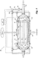
- Heat exchange system 100 includes a shell 102 having an interior with an inlet 104 and an outlet 106 wherein a first fluid circuit is defined from the inlet 104, through a heat exchange volume 108 within the interior of the shell 102, to the outlet 106, as indicated by the large vertical arrows in Fig. 1 .
- a first fluid circuit is defined from the inlet 104, through a heat exchange volume 108 within the interior of the shell 102, to the outlet 106, as indicated by the large vertical arrows in Fig. 1 .
- a pair of tubesheets 110 and 112 are mounted within the shell 102. Each of the tubesheet 110 and 112 divides between the heat exchange volume 108 and a respective plenum 114 and 116 of a second fluid circuit within the interior of the shell 102.
- a set of tubes 118 extends through the heat exchange volume 108.
- each tube 118 is in fluid communication with each plenum 114 and 116 through a respective pair of openings 120 though the respective tubesheets 110 and 112.
- the second fluid circuit includes the plena 114 and 116 and the interior passages of the tubes 118, and flow through the second fluid circuit is indicated schematically in Fig. 1 by the large horizontal arrows.
- a plurality of spray nozzles 122 are mounted in the plena 114 and 116 of the second fluid circuit, each with a spray outlet 124 (shown in Fig. 2 ) directed toward the respective tubesheets 110 and 112 for cleaning the tubesheets 110 and 112 with a submerged impingement jet issued from the spray nozzles 122.
- the jets are indicated schematically in Fig. 1 .
- the spray nozzle 122 includes a mechanism 126 configured to move the spray outlet 124 through a procession of angles relative to the respective tubesheet 110 or 112 to move the impingement jet over an area of the tubesheet 110 or 112.
- the mechanism 126 can be configured to move spray outlet 124 in two directions, e.g. along the direction B and about the axis A.
- the mechanism 126 includes fluid driven vanes and/or gears 128 for moving the spray outlet 124 under power of fluid passing through the spray nozzle 122. Thus no power source is needed for movement of the spray nozzles 122 beyond the fluid itself flowing through spray nozzles 122.
- FIG. 3 schematically shows an exemplary spray pattern produced by the impingement jet moving about the surface of tubesheet 110 as spray outlet 124 undergoes its procession.
- spray pattern shown in Fig. 3 is for purpose of example only, and that any suitable spray pattern or procession of angles can be used without departing from the scope of this disclosure.
- a spray nozzle with a fluid powered gear train is the IM 25 Nozzle available from Alfa Laval Inc of Richmond, Virginia. It should be noted that the IM 25 Nozzle includes two opposed spray outlets and it may be desirable in some applications to block off one of the spray outlets and/or modify the gear train to limit the angular procession so the impingement jet only traverses the tubesheet 110 or 112, not the inner surface of the respective end cap 130 or 132 or other non-tubesheet surfaces, which in some installations are coated with a tar or pitch type coating to prevent corrosion.
- the IM 25 Nozzle is only an example, and that any other suitable spray nozzle can be used without departing from the scope of this disclosure.
- an inlet conduit 134 is connected to end cap 130 in fluid communication with the inlet plenum 114 of the second fluid circuit for supplying fluid from an external source to the inlet plenum 114.
- the external source can be any suitable source of fluid.
- the external source can include river water, sea water, or the like.
- a secondary conduit 136 connects the spray nozzles 122 in fluid communication with the inlet conduit 134 for supplying fluid to be issued from the spray nozzles 122 as the impingement jet.
- a pump 138 is included in the secondary conduit 136 for raising pressure in the fluid supplied to be issued from the spray nozzles 122.
- the source of fluid for the secondary conduit is available at sufficient pressure, no pump 138 may be required.
- pressurized fluid may be simply scooped from the flow of sea water around a vessel if the vessel is traveling at sufficient speed.
- the secondary conduit could simply be tapped into or connected to the city water line, which in many cases has a higher pressure than the pressure at the secondary fluid circuit inlet for a condenser, for example.
- a filter 140 can be included in the secondary conduit 136, e.g., upstream of the pump 138, to reduce or prevent impurities fouling the spray nozzles 122.
- the spray nozzles 122 are all in fluid communication with the secondary conduit 136 through respective branches of conduit 136.
- the spray nozzles 122 in each plenum are arranged in a pattern configured to provide cleaning sprays to clean the tube sheet 110 or 112 completely on a plenum side thereof. While two spray nozzles 122 per plenum 114 and 116 are shown and described in the exemplary embodiment, those skilled in the art will readily appreciate that any suitable number of spray nozzles can be included in a given plenum, including none or one, without departing from the scope of this disclosure. For example, it may be suitable in some applications to have a single spray nozzle 122 in the inlet plenum 114, and no spray nozzles in the outlet plenum 116.
- controller 142 configured to activate and deactivate the spray nozzles 122 individually, and to control pumping through pump 138.
- Controller 142 allows for controlling pump and spray nozzles 122 in accordance with the method described below. Any suitable control scheme can be used.
- controller 142 can include one or more pressure regulator valves with timers, a touch screen or other user interface programmed system, a set of one or more manually operated valves, or any other suitable control scheme connected to activate/deactivate the one or more spray nozzles 122 together or individually.
- a method of cleaning in a heat exchange system includes issuing a jet from a spray nozzle, e.g., spray nozzle 122, to impinge on a tubesheet, e.g., tubesheets 110 and 112, within a shell of a heat exchanger to remove accumulations from the tubesheet, wherein the jet is submerged while it is impinging on the tubesheet.
- a spray nozzle e.g., spray nozzle 122
- a tubesheet e.g., tubesheets 110 and 112
- Multiple spray nozzles and jets can be used.
- Issuing the jet can include supplying fluid to the spray nozzle from a common source as fluid in a fluid circuit in which the jet is submerged, e.g., wherein the fluid issued from spray nozzles 122 is from the same source as the rest of the fluid supplied into inlet plenum 114. Issuing the jet can therefore be performed during and in line with operation of the heat exchanger, i.e. online operation of the spray nozzles and heat exchanger, including heat exchange between a first fluid circuit through the shell of the heat exchanger and a second fluid circuit fluidly isolated from the first fluid circuit, wherein the jet is submerged in fluid flowing in the second fluid circuit.
- Issuing the jet can be performed intermittently during operation of the heat exchanger, e.g., by activating and deactivating spray nozzles 122 and/or pump 138 using controller 142.
- Issuing the jet includes moving a spray outlet of the spray nozzle through a procession of angles relative to the tubesheet to move the impingement jet over an area of the tubesheet, e.g., as shown in Fig. 3 .
- a method of retrofitting incudes installing one or more spray nozzles, e.g., spray nozzles 122, in an end cap of a heat exchanger shell, e.g., end caps 130 and 132, so that the spray nozzle has a spray outlet directed toward a tubesheet, e.g., tubesheets 110 and 112, mounted within the shell,.
- spray nozzles e.g., spray nozzles 122
- the retrofit method can include installing one or more second spray nozzles in a second end cap of a heat exchanger shell opposite the first end cap, so that the second spray nozzle has a spray outlet directed toward a second tubesheet mounted within the shell as described above.
- the method of retrofitting can include installing a secondary conduit, e.g., secondary conduit 136 as described above.
- the method can include installing at least one of a controller, e.g., controller 142, connected to the spray nozzle for activation and deactivation of the spray nozzle, a pump, e.g., pump 138, in the secondary conduit for pressurization of fluid supplied to the spray nozzle, and a filter, e.g., filter 140, in the second conduit upstream of the pump to reduce or prevent impurities fouling the spray nozzle.
- a controller e.g., controller 142
- a pump e.g., pump 138
- a filter e.g., filter 140
Landscapes
- Engineering & Computer Science (AREA)
- Mechanical Engineering (AREA)
- General Engineering & Computer Science (AREA)
- Chemical & Material Sciences (AREA)
- Combustion & Propulsion (AREA)
- Physics & Mathematics (AREA)
- Thermal Sciences (AREA)
- Cleaning By Liquid Or Steam (AREA)
Description
- This application claims the benefit of and priority to
U.S. Patent Application Ser. No. 15/019,389 filed February 9, 2016 . - The present disclosure relates to a heat exchanger system according to the preamble part of claim 1, and to a method for cleaning tubesheets in heat exchangers, condensers, and the like, according to claim 11, e.g., while operating or shutdown without requiring disassembly. Such a system and method is known from
US 4 905 900 A . - Shell and tube heat exchangers can be used for exchanging heat between a first fluid in the shell, and a second fluid in the tubes passing through the shell. This arrangement can be used simply for heat exchange, but one specific application is in condensers such as used in steam powered systems. In such an application, spent steam enters the shell and flows over the tubes. There is a cool flow of water or other coolant passing through the tubes, and as heat transfers from the steam into the water through the tube walls, the steam condenses into the bottom of the shell or hotwell. Condensate from the bottom of the shell can then be recycled through the steam cycle in a closed system, or discharged into the environment in an open system.
- Typically the water passing through the cooling tubes is not distilled or purified water. Instead, it is common to use sea water, river water, or water otherwise drawn from the environment. Impurities and entities such as minerals, algae, biological organisms, and the like, can deposit themselves and can accumulate within the heat exchanger tubes, and on the tubesheets at the entrance and exit of the tubes.
- The accumulation of these deposits, known as fouling, in the tubes and tubesheets must be addressed or else the performance of the heat exchanger will diminish. In a steam powered plant, a shutdown of three or more days may be required in order to remove the deposits from the tubes and tubesheets. Some solutions to this problem have been used, such as systems that employ sponge ball cleaners that circulate through the tubes. While such systems may allow for cleaning in line with operation of the heat exchanger, they inevitably add complexity issues to the operation.
US 2013/0312794 A1 discloses an apparatus operable with a source of cleaning fluid including a spray mat and a positioning mechanism for moving the spray mat transversely into and out of one of the zones between two adjacent rows of heat exchange tubes.US 2006/0185691 A1 discloses a method and system utilizing a mobile cleaning unit for providing cleaning of heat exchanger tube bundles.US 2014/0158169 A1 discloses an improved portable cleaning system for use in cleaning heat exchanger tube bundles.WO 2014/158377 A1 discloses a method of cleaning sludge from the top of tubesheet of a nuclear steam generator. - Such conventional methods and systems have generally been considered satisfactory for their intended purpose. However, there is still a need in the art for improved cleaning of heat exchangers, condensers, and the like. The present disclosure provides a solution for this need according to claims 1 and 11. The dependent claims contain advantageous embodiments of the invention.
- A heat exchange system includes a shell having an interior with an inlet and an outlet wherein a first fluid circuit is defined from the inlet, through a heat exchange volume within the interior of the shell, to the outlet. A tubesheet is mounted within the shell dividing between the heat exchange volume and a plenum of a second fluid circuit within the interior of the shell. A set of tubes extend through the heat exchange volume, a respective interior passage of each tube being in fluid communication with the plenum through a respective opening though the tubesheet. The second fluid circuit includes the plenum and interior passages of the tubes. A spray nozzle or bank of nozzles is mounted in the plenum of the second fluid circuit with a spray outlet directed toward the tubesheet for cleaning the tubesheet with a submerged impingement jet issued from the spray nozzle(s). The spray nozzle(s) is/are configured to operate both during heat exchanger operation and/or when the heat exchanger is not operating.
- The spray nozzle can include a mechanism configured to move the spray outlet through a procession of angles relative to the tubesheet to move the impingement jet over a targeted area of the tubesheet. The mechanism can include at least one of vanes or driven gears for moving and directing the spray outlet in a spray pattern across the tubesheet under power of fluid passing through the spray nozzle. An inlet conduit can be connected in fluid communication with the plenum of the second fluid circuit for supplying fluid from an external source to the plenum, wherein a secondary conduit connects the spray nozzle in fluid communication with the inlet conduit for supplying fluid to be issued from the spray nozzle as the impingement jet. A pump or higher pressure source can be included in the secondary conduit for raising pressure in the fluid supplied to be issued from the spray nozzle, or if the source of fluid for the secondary conduit is at sufficient pressure no pump may be required. A filter can be included in the secondary conduit, e.g. upstream of the pump, to reduce or prevent impurities fouling the spray nozzle.
- The spray nozzle can be a first spray nozzle in a plurality of spray nozzles mounted in the plenum, e.g. wherein the spray nozzles are all in fluid communication with the secondary conduit. The spray nozzles can be arranged in a pattern configured to provide cleaning sprays to clean the tube sheet completely on a plenum side thereof. The spray nozzles can be each operatively connected to a controller configured to activate and deactivate the spray nozzles individually.
- The tubesheet can be a first tube sheet, the plenum can be a first plenum, and the spray nozzle can be a first spray nozzle. The system can include a second tubesheet mounted within the shell dividing between the heat exchange volume and a second plenum of the second fluid circuit within the interior of the shell, wherein each of the tubes extends between a respective opening in the first tubesheet and a respective opening in the second tubesheet for fluid communication between the first and second plena through the tubes. A second spray nozzle can be mounted in the second plenum with a spray outlet directed toward the second tubesheet for cleaning the second tubesheet with a submerged impingement jet issued from the second spray nozzle. A branch of the secondary conduit described above can connect the second spray nozzle in fluid communication with the inlet conduit for supplying fluid to be issued from the second spray nozzle.
- A method of cleaning in a heat exchange system includes issuing a jet from a spray nozzle to impinge on a tubesheet within a shell of a heat exchanger to remove and/or prevent accumulations from the tubesheet, wherein the jet is submerged. Issuing the jet can include supplying fluid to the spray nozzle from a common source as fluid in a fluid circuit in which the jet is submerged. Issuing the jet can be performed during and in line with operation of the heat exchanger including heat exchange between a first fluid circuit through the shell of the heat exchanger and a second fluid circuit fluidly isolated from the first fluid circuit, wherein the jet is submerged in fluid flowing in the second fluid circuit. Issuing the jet can be performed intermittently during operation of the heat exchanger. Issuing the jet can include moving a spray outlet of the spray nozzle through a procession of angles relative to the tubesheet to move the impingement jet over an area of the tubesheet.
- A method of retrofitting a heat exchange system incudes installing a spray nozzle in an end cap of a heat exchanger shell so that the spray nozzle has a spray outlet directed toward a tubesheet mounted within the shell, wherein the tubesheet divides between the heat exchange volume of a first fluid circuit within the shell, and a plenum of a second fluid circuit through the shell. The method can include installing a second spray nozzle in a second end cap of a heat exchanger shell opposite the first end cap, so that the second spray nozzle has a spray outlet directed toward a second tubesheet mounted within the shell as described above. The nozzle or nozzles can be installed so as to allow nozzle removal. The method of retrofitting can include installing a secondary conduit as described above. The method can include installing at least one of a controller connected to the spray nozzle for activation and deactivation of the spray nozzle, a pump in the secondary conduit for pressurization of fluid supplied to the spray nozzle, and a filter in the second conduit upstream of the pump to reduce or prevent impurities fouling the spray nozzle.
- These and other features of the systems and methods of the subject disclosure will become more readily apparent to those skilled in the art from the following detailed description of the preferred embodiments taken in conjunction with the drawings.
- So that those skilled in the art to which the subject disclosure appertains will readily understand how to make and use the devices and methods of the subject disclosure without undue experimentation, preferred embodiments thereof will be described in detail herein below with reference to certain figures, wherein:
-
Fig. 1 is a schematic view of an exemplary embodiment of a system constructed in accordance with the present disclosure, showing the fluid circuits and submerged impingement jets cleaning the tubesheets; -
Fig. 2 is a schematic view of exemplary embodiment of a gear or vane driven type of one of the spray nozzles ofFig. 1 , schematically indicating the fluid driven gear mechanism for driving the spray nozzle through a procession of spray angles; and -
Fig. 3 is a schematic end view of one of the tubesheets ofFig. 1 , showing an exemplary path of the impingement jet of the spray nozzle ofFig. 2 as it follows its procession of angles. - Reference will now be made to the drawings wherein like reference numerals identify similar structural features or aspects of the subject disclosure. For purposes of explanation and illustration, and not limitation, a partial view of an exemplary embodiment of a system in accordance with the disclosure is shown in
Fig. 1 and is designated generally byreference character 100. Other embodiments of systems in accordance with the disclosure, or aspects thereof, are provided inFigs. 2-3 , as will be described. The systems and methods described herein can be used for online and/or offline cleaning of tubesheets in heat exchangers such as condensers. -
Heat exchange system 100 includes ashell 102 having an interior with an inlet 104 and anoutlet 106 wherein a first fluid circuit is defined from the inlet 104, through a heat exchange volume 108 within the interior of theshell 102, to theoutlet 106, as indicated by the large vertical arrows inFig. 1 . For example, in a condenser, steam enters inlet 104, and condensate issues fromoutlet 106. A pair oftubesheets 110 and 112 are mounted within theshell 102. Each of thetubesheet 110 and 112 divides between the heat exchange volume 108 and arespective plenum 114 and 116 of a second fluid circuit within the interior of theshell 102. A set oftubes 118 extends through the heat exchange volume 108. For sake of clarity in illustrating, only threetubes 118 are shown inFig. 1 ; however those skilled in the art will readily appreciate that any suitable number oftubes 118 can be used without departing from the scope of this disclosure. A respective interior passage of eachtube 118 is in fluid communication with eachplenum 114 and 116 through a respective pair ofopenings 120 though the respective tubesheets 110 and 112. The second fluid circuit includes theplena 114 and 116 and the interior passages of thetubes 118, and flow through the second fluid circuit is indicated schematically inFig. 1 by the large horizontal arrows. A plurality ofspray nozzles 122 are mounted in theplena 114 and 116 of the second fluid circuit, each with a spray outlet 124 (shown inFig. 2 ) directed toward the respective tubesheets 110 and 112 for cleaning thetubesheets 110 and 112 with a submerged impingement jet issued from thespray nozzles 122. The jets are indicated schematically inFig. 1 . - With reference now to
Fig. 2 , one of thespray nozzles 122 is shown in greater detail. Thespray nozzle 122 includes amechanism 126 configured to move thespray outlet 124 through a procession of angles relative to therespective tubesheet 110 or 112 to move the impingement jet over an area of thetubesheet 110 or 112. For example, themechanism 126 can be configured to movespray outlet 124 in two directions, e.g. along the direction B and about the axis A. Themechanism 126 includes fluid driven vanes and/or gears 128 for moving thespray outlet 124 under power of fluid passing through thespray nozzle 122. Thus no power source is needed for movement of thespray nozzles 122 beyond the fluid itself flowing throughspray nozzles 122.Fig. 3 schematically shows an exemplary spray pattern produced by the impingement jet moving about the surface of tubesheet 110 asspray outlet 124 undergoes its procession. Those skilled in the art will readily appreciate that the spray pattern shown inFig. 3 is for purpose of example only, and that any suitable spray pattern or procession of angles can be used without departing from the scope of this disclosure. - An example of a spray nozzle with a fluid powered gear train is the IM 25 Nozzle available from Alfa Laval Inc of Richmond, Virginia. It should be noted that the IM 25 Nozzle includes two opposed spray outlets and it may be desirable in some applications to block off one of the spray outlets and/or modify the gear train to limit the angular procession so the impingement jet only traverses the
tubesheet 110 or 112, not the inner surface of therespective end cap - With reference again to
Fig. 1 , an inlet conduit 134 is connected to endcap 130 in fluid communication with the inlet plenum 114 of the second fluid circuit for supplying fluid from an external source to the inlet plenum 114. The external source can be any suitable source of fluid. For example, in a condenser application, the external source can include river water, sea water, or the like. Asecondary conduit 136 connects thespray nozzles 122 in fluid communication with the inlet conduit 134 for supplying fluid to be issued from thespray nozzles 122 as the impingement jet. A pump 138 is included in thesecondary conduit 136 for raising pressure in the fluid supplied to be issued from thespray nozzles 122. It is also contemplated that if the source of fluid for the secondary conduit is available at sufficient pressure, no pump 138 may be required. For example, in marine applications where sea water is used as the fluid of the second fluid circuit, pressurized fluid may be simply scooped from the flow of sea water around a vessel if the vessel is traveling at sufficient speed. Another example is if a city water supply is available at a higher pressure than the supply used as the fluid in the second fluid circuit, the secondary conduit could simply be tapped into or connected to the city water line, which in many cases has a higher pressure than the pressure at the secondary fluid circuit inlet for a condenser, for example. Afilter 140 can be included in thesecondary conduit 136, e.g., upstream of the pump 138, to reduce or prevent impurities fouling thespray nozzles 122. - The spray nozzles 122, e.g. two per
plenum 114 and 116, are all in fluid communication with thesecondary conduit 136 through respective branches ofconduit 136. Thespray nozzles 122 in each plenum are arranged in a pattern configured to provide cleaning sprays to clean thetube sheet 110 or 112 completely on a plenum side thereof. While twospray nozzles 122 perplenum 114 and 116 are shown and described in the exemplary embodiment, those skilled in the art will readily appreciate that any suitable number of spray nozzles can be included in a given plenum, including none or one, without departing from the scope of this disclosure. For example, it may be suitable in some applications to have asingle spray nozzle 122 in the inlet plenum 114, and no spray nozzles in theoutlet plenum 116. - The
spray nozzles 122 and pump 138 are each operatively connected to a controller 142 configured to activate and deactivate thespray nozzles 122 individually, and to control pumping through pump 138. Controller 142 allows for controlling pump andspray nozzles 122 in accordance with the method described below. Any suitable control scheme can be used. For example, controller 142 can include one or more pressure regulator valves with timers, a touch screen or other user interface programmed system, a set of one or more manually operated valves, or any other suitable control scheme connected to activate/deactivate the one ormore spray nozzles 122 together or individually. - A method of cleaning in a heat exchange system, e.g.,
heat exchange system 100, includes issuing a jet from a spray nozzle, e.g.,spray nozzle 122, to impinge on a tubesheet, e.g., tubesheets 110 and 112, within a shell of a heat exchanger to remove accumulations from the tubesheet, wherein the jet is submerged while it is impinging on the tubesheet. Multiple spray nozzles and jets can be used. Issuing the jet can include supplying fluid to the spray nozzle from a common source as fluid in a fluid circuit in which the jet is submerged, e.g., wherein the fluid issued fromspray nozzles 122 is from the same source as the rest of the fluid supplied into inlet plenum 114. Issuing the jet can therefore be performed during and in line with operation of the heat exchanger, i.e. online operation of the spray nozzles and heat exchanger, including heat exchange between a first fluid circuit through the shell of the heat exchanger and a second fluid circuit fluidly isolated from the first fluid circuit, wherein the jet is submerged in fluid flowing in the second fluid circuit. Issuing the jet can be performed intermittently during operation of the heat exchanger, e.g., by activating and deactivatingspray nozzles 122 and/or pump 138 using controller 142. Issuing the jet includes moving a spray outlet of the spray nozzle through a procession of angles relative to the tubesheet to move the impingement jet over an area of the tubesheet, e.g., as shown inFig. 3 . - While it is contemplated that heat exchangers in new installations can benefit from the systems and methods disclosed herein, it is also contemplated that a heat exchange system can be retrofitted to benefit from the systems and methods described herein. A method of retrofitting incudes installing one or more spray nozzles, e.g.,
spray nozzles 122, in an end cap of a heat exchanger shell, e.g.,end caps secondary conduit 136 as described above. The method can include installing at least one of a controller, e.g., controller 142, connected to the spray nozzle for activation and deactivation of the spray nozzle, a pump, e.g., pump 138, in the secondary conduit for pressurization of fluid supplied to the spray nozzle, and a filter, e.g.,filter 140, in the second conduit upstream of the pump to reduce or prevent impurities fouling the spray nozzle. - While shown and described in the exemplary context of a heat exchanger configured as a condenser, those skilled in the art will readily appreciate that the systems and methods disclosed herein can readily be applied to any other suitable type of heat exchanger tubesheet or submerged surface. For example, in food processing, it may be desirable to clean a tubesheet within a plenum using the same fluid, e.g. a food product such as milk or other liquid, that is flowing through the plenum itself.
- The methods and systems of the present disclosure, as described above and shown in the drawings, provide for internal heat exchanger cleaning with superior properties including online and/or offline operation for reduced shutdown and improved system performance. While the apparatus and methods of the subject disclosure have been shown and described with reference to preferred embodiments, those skilled in the art will readily appreciate that changes and/or modifications may be made thereto without departing from the scope of the subject disclosure as defined by the appended claims.
Claims (14)
- A heat exchange system (100) including:a shell (102) having an interior with an inlet (104) and an outlet (106) wherein a first fluid circuit is defined from the inlet (104), through a heat exchange volume (108) within the interior of the shell (102), to the outlet (106);a set of tubes (118) extending through the heat exchange volume (108), anda spray nozzle (122),a tubesheet (110, 112) is mounted within the shell (102) dividing between the heat exchange volume (108) and a plenum (114, 116) of a second fluid circuit within the interior of the shell (102);that a respective interior passage of each tube (118) is in fluid communication with the plenum (114, 116) through a respective opening (120) through the tubesheet (110, 112), wherein the second fluid circuit includes the plenum (114, 116) and interior passages of the tubes (118); characterised in that the spray nozzle (122) is mounted in the plenum (114, 116) of the second fluid circuit with a spray outlet (124) directed toward the tubesheet (110. 112) for cleaning the tubesheet (110, 112) with a submerged impingement jet issued from the spray nozzle (122); and in that the spray nozzle (122) includes a mechanism (126) configured to move the spray outlet (124) through a procession of angles relative to the tubesheet (110, 112) in two directions (A, B) to move the impingement jet over an area of the tubesheet (110, 112).
- A system as recited in claim 1, wherein the mechanism (126) includes at least one of fluid driven gears (128) or vanes (128) for moving the spray outlet (124) under power of fluid passing through the spray nozzle (122).
- A system as recited in claim 1, wherein an inlet conduit (134) is connected in fluid communication with the plenum (114, 116) of the second fluid circuit for supplying fluid from an external source to the plenum (114, 116), wherein a secondary conduit (136) connects the spray nozzle (122) in fluid communication with the inlet conduit (134) for supplying fluid to be issued from the spray nozzle (122) as the impingement jet.
- A system as recited in claim 3, wherein at least one of a pump (138) or higher pressure source is included in the secondary conduit (136) for raising pressure in the fluid supplied to be issued from the spray nozzle (122).
- A system as recited in claim 4, wherein a filter (140) is included in the secondary conduit (136) upstream of the pump (138) to reduce or prevent impurities fouling the spray nozzle (122).
- A system as recited in claim 3, wherein the spray nozzle (122) is a first spray nozzle in a plurality of spray nozzles mounted in the plenum(114, 116), wherein the spray nozzles (122) are all in fluid communication with the secondary conduit (136).
- A system as recited in claim 6, wherein the spray nozzles (122) are arranged in a pattern configured to provide cleaning sprays to clean the tube sheet (110, 112) completely on a plenum side thereof.
- A system as recited in claim 7, wherein the spray nozzles (122) are each operatively connected to a controller (142) configured to activate and deactivate the spray nozzles (122) individually.
- A system as recited in claim 1, wherein the tubesheet (110) is a first tube sheet, the plenum (114) is a first plenum, the spray nozzle (122) is a first spray nozzle, and further comprising:a second tubesheet (112) mounted within the shell (102) dividing between the heat exchange volume and a second plenum (116) of the second fluid circuit within the interior of the shell (102), wherein each of the tubes (118) extends between a respective opening in the first tubesheet (110)and a respective opening in the second tubesheet (112) for fluid communication between the first and second plena (114, 116) through the tubes (118); anda second spray nozzle (122) mounted in the second plenum (116)with a spray outlet directed toward the second tubesheet (112) for cleaning the second tubesheet (112) with a submerged impingement jet issued from the second spray nozzle (122).
- A system as recited in claim 9, wherein an inlet conduit (134) is connected in fluid communication with the plenum (116) of the second fluid circuit for supplying fluid from an external source to the plenum (116), wherein a secondary conduit (136) connects the first spray nozzle in fluid communication with the inlet conduit (134) for supplying fluid to be issued from the first spray nozzle (122), and wherein a branch of the secondary conduit (136) connects the second spray nozzle (122) in fluid communication with the inlet conduit (134) for supplying fluid to be issued from the second spray nozzle (122).
- A method of cleaning in a heat exchange system according to claim 1 comprising:
issuing a jet from a spray nozzle (122) to impinge on a tubesheet (110, 112) within a shell (102) of a heat exchanger (100) to remove accumulations from the tubesheet (11., 112), wherein the jet is submerged. - A method as recited in claim 11, wherein issuing the jet includes supplying fluid to the spray nozzle (122) from a common source as fluid in a fluid circuit in which the jet is submerged.
- A method as recited in claim 11, wherein issuing the jet is performed during and in line with operation of the heat exchanger (100) including heat exchange between a first fluid circuit through the shell of the heat exchanger (100) and a second fluid circuit fluidly isolated from the first fluid circuit, wherein the jet is submerged in fluid flowing in the second fluid circuit, wherein issuing the jet particularly includes moving a spray outlet (124) of the spray nozzle (122) through a procession of angles relative to the tubesheet (110, 112) to move the impingement jet over an area of the tubesheet (110, 112).
- A method as recited in claim 11, wherein issuing the jet is performed at least one of intermittently during operation of the heat exchanger (100) or with the heat exchanger (100) offline.
Applications Claiming Priority (2)
| Application Number | Priority Date | Filing Date | Title |
|---|---|---|---|
| US15/019,389 US10502510B2 (en) | 2016-02-09 | 2016-02-09 | Cleaning tubesheets of heat exchangers |
| PCT/US2017/015968 WO2017139146A1 (en) | 2016-02-09 | 2017-02-01 | Cleaning tubesheets of heat exchangers |
Publications (4)
| Publication Number | Publication Date |
|---|---|
| EP3414511A1 EP3414511A1 (en) | 2018-12-19 |
| EP3414511A4 EP3414511A4 (en) | 2019-07-24 |
| EP3414511B1 true EP3414511B1 (en) | 2020-12-30 |
| EP3414511B8 EP3414511B8 (en) | 2021-03-17 |
Family
ID=59498211
Family Applications (1)
| Application Number | Title | Priority Date | Filing Date |
|---|---|---|---|
| EP17750583.1A Active EP3414511B8 (en) | 2016-02-09 | 2017-02-01 | Cleaning tubesheets of heat exchangers |
Country Status (4)
| Country | Link |
|---|---|
| US (2) | US10502510B2 (en) |
| EP (1) | EP3414511B8 (en) |
| ES (1) | ES2862429T3 (en) |
| WO (1) | WO2017139146A1 (en) |
Families Citing this family (4)
| Publication number | Priority date | Publication date | Assignee | Title |
|---|---|---|---|---|
| CN111141161A (en) * | 2018-11-06 | 2020-05-12 | 金川集团股份有限公司 | Heat exchanger for material heat exchange and heat energy recovery |
| WO2020260730A1 (en) * | 2019-06-27 | 2020-12-30 | Ruiz Herrera Luis Javier | Thermolysis system and method for obtaining recovered carbon black and fuel from disused tyres |
| CN110542323A (en) * | 2019-09-02 | 2019-12-06 | 大唐东营发电有限公司 | heat conduction breather of condenser for power plant |
| CN111649601B (en) * | 2020-06-29 | 2022-04-19 | 东和恩泰热能技术(江苏)有限公司 | Large-scale marine vacuum condenser |
Family Cites Families (49)
| Publication number | Priority date | Publication date | Assignee | Title |
|---|---|---|---|---|
| US3123132A (en) | 1964-03-03 | Device for fluid cleaning of heat | ||
| DE344141C (en) * | 1916-11-18 | 1921-11-17 | Arvid Westerberg | Cleaning device, especially for blowing out vertical heating pipes |
| US1589980A (en) | 1925-04-15 | 1926-06-22 | Miller Willard Bennett | Power condenser washer |
| US1807457A (en) * | 1927-10-25 | 1931-05-26 | Henry T Weis | Means for cleaning condensers and the like |
| US1930515A (en) | 1930-04-18 | 1933-10-17 | Ivan D Eby | Soot blower |
| US2801824A (en) | 1953-02-02 | 1957-08-06 | Taprogge Josef | Self-cleaning heat exchanger |
| US3045978A (en) * | 1960-05-02 | 1962-07-24 | Koppers Co Inc | Tubular boiler or heat exchanger with soot blower |
| CH426905A (en) | 1961-06-02 | 1966-12-31 | Maschf Augsburg Nuernberg Ag | Method and device for cleaning surface tube condensers and other surface tube heat exchangers |
| US3637138A (en) | 1970-05-18 | 1972-01-25 | Sybron Corp | Tank cleaning machine |
| US4276856A (en) | 1978-12-28 | 1981-07-07 | Westinghouse Electric Corp. | Steam generator sludge lancing method |
| US4234993A (en) | 1979-05-30 | 1980-11-25 | Kintner Edwin K | Condenser cleaning system using sponge balls |
| JPS5714193A (en) * | 1980-06-30 | 1982-01-25 | Hitachi Ltd | Distributing and controlling method of cleaning balls |
| US4492186A (en) | 1982-08-23 | 1985-01-08 | Proto-Power Management Corporation | Steam generator sludge removal method |
| US4498427A (en) | 1983-03-21 | 1985-02-12 | Halliburton Company | Sludge lance with multiple nozzle jet head |
| US4566406A (en) | 1983-07-13 | 1986-01-28 | Westinghouse Electric Corp. | Sludge removing apparatus for a steam generator |
| US4505128A (en) * | 1983-08-08 | 1985-03-19 | Bio-Care Incorporated | Compressor system for discharging dry air |
| FR2568985A1 (en) | 1984-03-14 | 1986-02-14 | Julliard Jacques | Novel principle for removing deposits accumulated at the tube plate of steam generators of pressurised water nuclear power stations |
| US4676201A (en) | 1984-07-25 | 1987-06-30 | Westinghouse Electric Corp. | Method and apparatus for removal of residual sludge from a nuclear steam generator |
| US4774975A (en) | 1984-09-17 | 1988-10-04 | Westinghouse Electric Corp. | Method and apparatus for providing oscillating contaminant-removal stream |
| CN85106441A (en) | 1985-08-27 | 1987-03-18 | 西屋电气公司 | Be used for removing the method and apparatus of the remaining sludge of nuclear boiler |
| JPS62109000A (en) * | 1985-11-07 | 1987-05-20 | Takao Sakamoto | Cleaning of internal surface of heat transfer tube in heat exchanger |
| US4715324A (en) | 1985-11-26 | 1987-12-29 | Apex Technologies, Inc. | Nuclear steam generator sludge lancing method and apparatus |
| US4905900A (en) * | 1986-08-29 | 1990-03-06 | Anco Engineers, Inc. | Water cannon apparatus for cleaning a tube bundle heat exchanger, boiler, condenser, or the like |
| ES2022803B3 (en) | 1986-10-30 | 1991-12-16 | Anco Eng Inc | CLEANING METHOD BY IMPULSE PRESSURE OF A TUBULAR BEAM HEAT EXCHANGER. |
| US5092280A (en) | 1988-04-19 | 1992-03-03 | Westinghouse Electric Corp. | Pressure pulse cleaning apparatus |
| US4899697A (en) | 1988-04-19 | 1990-02-13 | Westinghouse Electric Corp. | Pressure pulse cleaning apparatus |
| DE68906158T2 (en) | 1989-10-11 | 1993-10-28 | Westinghouse Electric Corp | Pressure pulsing cleaning process. |
| US5019329A (en) | 1989-12-26 | 1991-05-28 | Westinghouse Electric Corp. | System and method for vertically flushing a steam generator during a shock wave cleaning operation |
| NL9000919A (en) * | 1990-04-18 | 1991-11-18 | Eskla Bv | METHOD FOR CLEANING THE WALLS OF HEAT EXCHANGERS AND HEAT EXCHANGER WITH AGENTS FOR THIS CLEANING |
| US5083606A (en) | 1990-08-09 | 1992-01-28 | Texas Utilities Electric Company | Structure and method for on-line inspection of condenser tubes |
| US5238502A (en) | 1992-01-22 | 1993-08-24 | Jenkins Jerry Y | Condenser backflush system and method for use |
| CA2115109C (en) | 1994-02-01 | 2000-04-25 | James P. Vanderberg | Automated sludge lance |
| US6672257B1 (en) | 1994-05-06 | 2004-01-06 | Foster-Miller, Inc. | Upper bundle steam generator cleaning system and method |
| US5764717A (en) | 1995-08-29 | 1998-06-09 | Westinghouse Electric Corporation | Chemical cleaning method for the removal of scale sludge and other deposits from nuclear steam generators |
| FR2742858B1 (en) | 1995-12-22 | 1998-03-06 | Framatome Sa | METHOD AND DEVICE FOR CLEANING A TUBULAR PLATE OF A HEAT EXCHANGER FROM THE INSIDE OF THE HEAT EXCHANGER BEAM |
| JP3171094B2 (en) * | 1996-02-23 | 2001-05-28 | 日本鋼管株式会社 | Method and apparatus for preventing deposition of particles in heat exchanger |
| DE10044799C1 (en) * | 2000-09-11 | 2002-06-27 | Clyde Bergemann Gmbh | Ball joint bearing for a water lance of a water lance blower |
| US6609531B2 (en) | 2001-09-24 | 2003-08-26 | Edward R. Lesko | Condenser tube cleaning nozzle |
| ES2343577T3 (en) | 2005-02-24 | 2010-08-04 | National Heat Exchange Cleaning Corp. | METHOD AND SYSTEM FOR CLEANING HACES OF HEAT EXCHANGER TUBES. |
| CN100582641C (en) * | 2005-04-30 | 2010-01-20 | 江从铨 | Online automatic flushing device and method for gas turbine generator condenser |
| WO2008005870A2 (en) | 2006-06-30 | 2008-01-10 | Dominion Engineering Inc. | Low-pressure sludge removal method and apparatus using coherent jet nozzles |
| US8238510B2 (en) | 2007-07-03 | 2012-08-07 | Westinghouse Electric Company Llc | Steam generator dual head sludge lance and process lancing system |
| US8646514B2 (en) | 2009-09-01 | 2014-02-11 | Yonggang Ni | Front end water box with on-line rubber ball cleaning function in the tubular condenser of a water cooled chiller |
| EP2496905B1 (en) | 2009-11-03 | 2021-01-06 | Westinghouse Electric Company LLC | Miniature sludge lance apparatus |
| US8646416B2 (en) | 2009-11-03 | 2014-02-11 | Westinghouse Electric Company Llc | Miniature sludge lance apparatus |
| US8136540B2 (en) | 2010-07-30 | 2012-03-20 | Hays Gary I | Cleaning system having heated cleaning enclosure for cleaning heat exchanger tube bundles |
| US8974607B2 (en) | 2011-12-28 | 2015-03-10 | Saudi Arabian Oil Company | Cleaning apparatus for heat exchange tubes of air cooled heat exchangers |
| FR3002166B1 (en) | 2013-02-19 | 2015-04-17 | Jean Greppo | ASSEMBLY FOR REMOVING A SURFACE BY PROJECTING WATER AT HIGH PRESSURE ON THIS SURFACE |
| US20140261246A1 (en) | 2013-03-14 | 2014-09-18 | Westinghouse Electric Company Llc | Localized vacuum removal of steam generator deposits |
-
2016
- 2016-02-09 US US15/019,389 patent/US10502510B2/en active Active
-
2017
- 2017-02-01 EP EP17750583.1A patent/EP3414511B8/en active Active
- 2017-02-01 ES ES17750583T patent/ES2862429T3/en active Active
- 2017-02-01 WO PCT/US2017/015968 patent/WO2017139146A1/en not_active Ceased
-
2019
- 2019-12-03 US US16/701,379 patent/US11561054B2/en active Active
Non-Patent Citations (1)
| Title |
|---|
| None * |
Also Published As
| Publication number | Publication date |
|---|---|
| ES2862429T3 (en) | 2021-10-07 |
| US10502510B2 (en) | 2019-12-10 |
| WO2017139146A1 (en) | 2017-08-17 |
| EP3414511B8 (en) | 2021-03-17 |
| US11561054B2 (en) | 2023-01-24 |
| EP3414511A1 (en) | 2018-12-19 |
| US20170227308A1 (en) | 2017-08-10 |
| US20200103186A1 (en) | 2020-04-02 |
| EP3414511A4 (en) | 2019-07-24 |
Similar Documents
| Publication | Publication Date | Title |
|---|---|---|
| US11561054B2 (en) | Cleaning tubesheets of heat exchangers | |
| US4750547A (en) | Method for cleaning inner surfaces of heat-transfer tubes in a heat-exchanger | |
| US1795348A (en) | Condenser-cleaning system | |
| AU2017254834B2 (en) | Wet-scrubber for cleaning of polluted gas such as flue gas | |
| JP2018009783A (en) | Condenser heat transfer tube coating system | |
| CN201964832U (en) | Evaporation-type air cooler | |
| JP6096768B2 (en) | Thermal energy system and method of operating thermal energy system | |
| WO2010095110A2 (en) | Self-cleaning heat exchanger | |
| KR100743909B1 (en) | Multipurpose Seawater Exchange System with Vessel Ballast Water Sediment Treatment | |
| CN114940521A (en) | Modularized horizontal pipe type evaporator unit, cleaning device, evaporator and cleaning application method | |
| WO2004028978A1 (en) | Low or zero bleed water discharge cooling tower system | |
| CN106524825B (en) | A kind of kestner long-tube evaporator antiscaling, descaling method and system | |
| CN108793292B (en) | Heat exchange device utilizing waste heat | |
| JP2007205686A (en) | Cooling device | |
| EP3017259A1 (en) | Shell and tube heat exchanger arrangement | |
| CN214371847U (en) | Counter-flow cooling tower without tube pass replacement and cleaning during parking | |
| GB2472782A (en) | Cleaning of finned heat exchangers where the cleaning fluid flows from the interior to the exterior | |
| CN202915762U (en) | Transverse flow plate type evaporative air cooler | |
| CN121739761A (en) | Environment-friendly industrial wastewater waste heat recycling device and application thereof | |
| US20220316697A1 (en) | Working fluid evaporator for an etm plant comprising a suitable spraying system | |
| KR20210037392A (en) | Air handling unit | |
| SE502890C2 (en) | Vacuum vessels for continuous or semi-continuous treatment of fatty oils | |
| RU2600725C2 (en) | Passive pressure control device in shell, shell and corresponding installation | |
| JP6300234B2 (en) | Valve system, heat exchanger cooling system | |
| JPH02118302A (en) | Moisture separation heater |
Legal Events
| Date | Code | Title | Description |
|---|---|---|---|
| STAA | Information on the status of an ep patent application or granted ep patent |
Free format text: STATUS: THE INTERNATIONAL PUBLICATION HAS BEEN MADE |
|
| PUAI | Public reference made under article 153(3) epc to a published international application that has entered the european phase |
Free format text: ORIGINAL CODE: 0009012 |
|
| STAA | Information on the status of an ep patent application or granted ep patent |
Free format text: STATUS: REQUEST FOR EXAMINATION WAS MADE |
|
| 17P | Request for examination filed |
Effective date: 20180906 |
|
| AK | Designated contracting states |
Kind code of ref document: A1 Designated state(s): AL AT BE BG CH CY CZ DE DK EE ES FI FR GB GR HR HU IE IS IT LI LT LU LV MC MK MT NL NO PL PT RO RS SE SI SK SM TR |
|
| AX | Request for extension of the european patent |
Extension state: BA ME |
|
| DAV | Request for validation of the european patent (deleted) | ||
| DAX | Request for extension of the european patent (deleted) | ||
| A4 | Supplementary search report drawn up and despatched |
Effective date: 20190624 |
|
| RIC1 | Information provided on ipc code assigned before grant |
Ipc: F28G 15/00 20060101ALI20190617BHEP Ipc: F28G 15/02 20060101ALI20190617BHEP Ipc: F28G 1/16 20060101AFI20190617BHEP Ipc: B08B 3/02 20060101ALI20190617BHEP |
|
| GRAP | Despatch of communication of intention to grant a patent |
Free format text: ORIGINAL CODE: EPIDOSNIGR1 |
|
| STAA | Information on the status of an ep patent application or granted ep patent |
Free format text: STATUS: GRANT OF PATENT IS INTENDED |
|
| INTG | Intention to grant announced |
Effective date: 20200709 |
|
| GRAS | Grant fee paid |
Free format text: ORIGINAL CODE: EPIDOSNIGR3 |
|
| GRAA | (expected) grant |
Free format text: ORIGINAL CODE: 0009210 |
|
| STAA | Information on the status of an ep patent application or granted ep patent |
Free format text: STATUS: THE PATENT HAS BEEN GRANTED |
|
| AK | Designated contracting states |
Kind code of ref document: B1 Designated state(s): AL AT BE BG CH CY CZ DE DK EE ES FI FR GB GR HR HU IE IS IT LI LT LU LV MC MK MT NL NO PL PT RO RS SE SI SK SM TR |
|
| REG | Reference to a national code |
Ref country code: GB Ref legal event code: FG4D |
|
| REG | Reference to a national code |
Ref country code: DE Ref legal event code: R096 Ref document number: 602017030500 Country of ref document: DE |
|
| REG | Reference to a national code |
Ref country code: AT Ref legal event code: REF Ref document number: 1350365 Country of ref document: AT Kind code of ref document: T Effective date: 20210115 |
|
| REG | Reference to a national code |
Ref country code: DE Ref legal event code: R081 Ref document number: 602017030500 Country of ref document: DE Owner name: THERMAL ENGINEERING INTERNATIONAL (USA) INC., , US Free format text: FORMER OWNER: BABCOCK POWER SERVICES, INC., MARLBOROUGH, MA, US |
|
| REG | Reference to a national code |
Ref country code: IE Ref legal event code: FG4D |
|
| RAP2 | Party data changed (patent owner data changed or rights of a patent transferred) |
Owner name: THERMAL ENGINEERING INTERNATIONAL (USA) INC. |
|
| REG | Reference to a national code |
Ref country code: CH Ref legal event code: PK Free format text: BERICHTIGUNG B8 |
|
| PG25 | Lapsed in a contracting state [announced via postgrant information from national office to epo] |
Ref country code: FI Free format text: LAPSE BECAUSE OF FAILURE TO SUBMIT A TRANSLATION OF THE DESCRIPTION OR TO PAY THE FEE WITHIN THE PRESCRIBED TIME-LIMIT Effective date: 20201230 Ref country code: GR Free format text: LAPSE BECAUSE OF FAILURE TO SUBMIT A TRANSLATION OF THE DESCRIPTION OR TO PAY THE FEE WITHIN THE PRESCRIBED TIME-LIMIT Effective date: 20210331 Ref country code: RS Free format text: LAPSE BECAUSE OF FAILURE TO SUBMIT A TRANSLATION OF THE DESCRIPTION OR TO PAY THE FEE WITHIN THE PRESCRIBED TIME-LIMIT Effective date: 20201230 Ref country code: NO Free format text: LAPSE BECAUSE OF FAILURE TO SUBMIT A TRANSLATION OF THE DESCRIPTION OR TO PAY THE FEE WITHIN THE PRESCRIBED TIME-LIMIT Effective date: 20210330 |
|
| REG | Reference to a national code |
Ref country code: AT Ref legal event code: MK05 Ref document number: 1350365 Country of ref document: AT Kind code of ref document: T Effective date: 20201230 |
|
| PG25 | Lapsed in a contracting state [announced via postgrant information from national office to epo] |
Ref country code: SE Free format text: LAPSE BECAUSE OF FAILURE TO SUBMIT A TRANSLATION OF THE DESCRIPTION OR TO PAY THE FEE WITHIN THE PRESCRIBED TIME-LIMIT Effective date: 20201230 Ref country code: LV Free format text: LAPSE BECAUSE OF FAILURE TO SUBMIT A TRANSLATION OF THE DESCRIPTION OR TO PAY THE FEE WITHIN THE PRESCRIBED TIME-LIMIT Effective date: 20201230 Ref country code: BG Free format text: LAPSE BECAUSE OF FAILURE TO SUBMIT A TRANSLATION OF THE DESCRIPTION OR TO PAY THE FEE WITHIN THE PRESCRIBED TIME-LIMIT Effective date: 20210330 |
|
| REG | Reference to a national code |
Ref country code: NL Ref legal event code: MP Effective date: 20201230 |
|
| PG25 | Lapsed in a contracting state [announced via postgrant information from national office to epo] |
Ref country code: HR Free format text: LAPSE BECAUSE OF FAILURE TO SUBMIT A TRANSLATION OF THE DESCRIPTION OR TO PAY THE FEE WITHIN THE PRESCRIBED TIME-LIMIT Effective date: 20201230 |
|
| REG | Reference to a national code |
Ref country code: LT Ref legal event code: MG9D |
|
| PG25 | Lapsed in a contracting state [announced via postgrant information from national office to epo] |
Ref country code: PT Free format text: LAPSE BECAUSE OF FAILURE TO SUBMIT A TRANSLATION OF THE DESCRIPTION OR TO PAY THE FEE WITHIN THE PRESCRIBED TIME-LIMIT Effective date: 20210430 Ref country code: SK Free format text: LAPSE BECAUSE OF FAILURE TO SUBMIT A TRANSLATION OF THE DESCRIPTION OR TO PAY THE FEE WITHIN THE PRESCRIBED TIME-LIMIT Effective date: 20201230 Ref country code: RO Free format text: LAPSE BECAUSE OF FAILURE TO SUBMIT A TRANSLATION OF THE DESCRIPTION OR TO PAY THE FEE WITHIN THE PRESCRIBED TIME-LIMIT Effective date: 20201230 Ref country code: EE Free format text: LAPSE BECAUSE OF FAILURE TO SUBMIT A TRANSLATION OF THE DESCRIPTION OR TO PAY THE FEE WITHIN THE PRESCRIBED TIME-LIMIT Effective date: 20201230 Ref country code: LT Free format text: LAPSE BECAUSE OF FAILURE TO SUBMIT A TRANSLATION OF THE DESCRIPTION OR TO PAY THE FEE WITHIN THE PRESCRIBED TIME-LIMIT Effective date: 20201230 |
|
| PG25 | Lapsed in a contracting state [announced via postgrant information from national office to epo] |
Ref country code: AT Free format text: LAPSE BECAUSE OF FAILURE TO SUBMIT A TRANSLATION OF THE DESCRIPTION OR TO PAY THE FEE WITHIN THE PRESCRIBED TIME-LIMIT Effective date: 20201230 Ref country code: PL Free format text: LAPSE BECAUSE OF FAILURE TO SUBMIT A TRANSLATION OF THE DESCRIPTION OR TO PAY THE FEE WITHIN THE PRESCRIBED TIME-LIMIT Effective date: 20201230 |
|
| REG | Reference to a national code |
Ref country code: DE Ref legal event code: R119 Ref document number: 602017030500 Country of ref document: DE |
|
| PG25 | Lapsed in a contracting state [announced via postgrant information from national office to epo] |
Ref country code: MC Free format text: LAPSE BECAUSE OF FAILURE TO SUBMIT A TRANSLATION OF THE DESCRIPTION OR TO PAY THE FEE WITHIN THE PRESCRIBED TIME-LIMIT Effective date: 20201230 Ref country code: IS Free format text: LAPSE BECAUSE OF FAILURE TO SUBMIT A TRANSLATION OF THE DESCRIPTION OR TO PAY THE FEE WITHIN THE PRESCRIBED TIME-LIMIT Effective date: 20210430 |
|
| REG | Reference to a national code |
Ref country code: ES Ref legal event code: FG2A Ref document number: 2862429 Country of ref document: ES Kind code of ref document: T3 Effective date: 20211007 |
|
| REG | Reference to a national code |
Ref country code: BE Ref legal event code: MM Effective date: 20210228 |
|
| PG25 | Lapsed in a contracting state [announced via postgrant information from national office to epo] |
Ref country code: CH Free format text: LAPSE BECAUSE OF NON-PAYMENT OF DUE FEES Effective date: 20210228 Ref country code: AL Free format text: LAPSE BECAUSE OF FAILURE TO SUBMIT A TRANSLATION OF THE DESCRIPTION OR TO PAY THE FEE WITHIN THE PRESCRIBED TIME-LIMIT Effective date: 20201230 Ref country code: LI Free format text: LAPSE BECAUSE OF NON-PAYMENT OF DUE FEES Effective date: 20210228 Ref country code: LU Free format text: LAPSE BECAUSE OF NON-PAYMENT OF DUE FEES Effective date: 20210201 Ref country code: CZ Free format text: LAPSE BECAUSE OF FAILURE TO SUBMIT A TRANSLATION OF THE DESCRIPTION OR TO PAY THE FEE WITHIN THE PRESCRIBED TIME-LIMIT Effective date: 20201230 |
|
| PLBE | No opposition filed within time limit |
Free format text: ORIGINAL CODE: 0009261 |
|
| STAA | Information on the status of an ep patent application or granted ep patent |
Free format text: STATUS: NO OPPOSITION FILED WITHIN TIME LIMIT |
|
| GBPC | Gb: european patent ceased through non-payment of renewal fee |
Effective date: 20210330 |
|
| PG25 | Lapsed in a contracting state [announced via postgrant information from national office to epo] |
Ref country code: DK Free format text: LAPSE BECAUSE OF FAILURE TO SUBMIT A TRANSLATION OF THE DESCRIPTION OR TO PAY THE FEE WITHIN THE PRESCRIBED TIME-LIMIT Effective date: 20201230 |
|
| 26N | No opposition filed |
Effective date: 20211001 |
|
| PG25 | Lapsed in a contracting state [announced via postgrant information from national office to epo] |
Ref country code: FR Free format text: LAPSE BECAUSE OF NON-PAYMENT OF DUE FEES Effective date: 20210228 Ref country code: IE Free format text: LAPSE BECAUSE OF NON-PAYMENT OF DUE FEES Effective date: 20210201 Ref country code: GB Free format text: LAPSE BECAUSE OF NON-PAYMENT OF DUE FEES Effective date: 20210330 Ref country code: DE Free format text: LAPSE BECAUSE OF NON-PAYMENT OF DUE FEES Effective date: 20210901 |
|
| PG25 | Lapsed in a contracting state [announced via postgrant information from national office to epo] |
Ref country code: SI Free format text: LAPSE BECAUSE OF FAILURE TO SUBMIT A TRANSLATION OF THE DESCRIPTION OR TO PAY THE FEE WITHIN THE PRESCRIBED TIME-LIMIT Effective date: 20201230 |
|
| PG25 | Lapsed in a contracting state [announced via postgrant information from national office to epo] |
Ref country code: IS Free format text: LAPSE BECAUSE OF FAILURE TO SUBMIT A TRANSLATION OF THE DESCRIPTION OR TO PAY THE FEE WITHIN THE PRESCRIBED TIME-LIMIT Effective date: 20210430 |
|
| PG25 | Lapsed in a contracting state [announced via postgrant information from national office to epo] |
Ref country code: BE Free format text: LAPSE BECAUSE OF NON-PAYMENT OF DUE FEES Effective date: 20210228 |
|
| PG25 | Lapsed in a contracting state [announced via postgrant information from national office to epo] |
Ref country code: NL Free format text: LAPSE BECAUSE OF NON-PAYMENT OF DUE FEES Effective date: 20201230 Ref country code: CY Free format text: LAPSE BECAUSE OF FAILURE TO SUBMIT A TRANSLATION OF THE DESCRIPTION OR TO PAY THE FEE WITHIN THE PRESCRIBED TIME-LIMIT Effective date: 20201230 |
|
| PG25 | Lapsed in a contracting state [announced via postgrant information from national office to epo] |
Ref country code: SM Free format text: LAPSE BECAUSE OF FAILURE TO SUBMIT A TRANSLATION OF THE DESCRIPTION OR TO PAY THE FEE WITHIN THE PRESCRIBED TIME-LIMIT Effective date: 20201230 Ref country code: HU Free format text: LAPSE BECAUSE OF FAILURE TO SUBMIT A TRANSLATION OF THE DESCRIPTION OR TO PAY THE FEE WITHIN THE PRESCRIBED TIME-LIMIT; INVALID AB INITIO Effective date: 20170201 |
|
| PG25 | Lapsed in a contracting state [announced via postgrant information from national office to epo] |
Ref country code: MK Free format text: LAPSE BECAUSE OF FAILURE TO SUBMIT A TRANSLATION OF THE DESCRIPTION OR TO PAY THE FEE WITHIN THE PRESCRIBED TIME-LIMIT Effective date: 20201230 |
|
| PG25 | Lapsed in a contracting state [announced via postgrant information from national office to epo] |
Ref country code: TR Free format text: LAPSE BECAUSE OF FAILURE TO SUBMIT A TRANSLATION OF THE DESCRIPTION OR TO PAY THE FEE WITHIN THE PRESCRIBED TIME-LIMIT Effective date: 20201230 |
|
| PG25 | Lapsed in a contracting state [announced via postgrant information from national office to epo] |
Ref country code: MT Free format text: LAPSE BECAUSE OF FAILURE TO SUBMIT A TRANSLATION OF THE DESCRIPTION OR TO PAY THE FEE WITHIN THE PRESCRIBED TIME-LIMIT Effective date: 20201230 |
|
| PGFP | Annual fee paid to national office [announced via postgrant information from national office to epo] |
Ref country code: ES Payment date: 20260302 Year of fee payment: 10 |
|
| PGFP | Annual fee paid to national office [announced via postgrant information from national office to epo] |
Ref country code: IT Payment date: 20260219 Year of fee payment: 10 |