EP3414432B1 - Fixing system for panels and turbomachine enclosure comprising such system - Google Patents
Fixing system for panels and turbomachine enclosure comprising such system Download PDFInfo
- Publication number
- EP3414432B1 EP3414432B1 EP17703963.3A EP17703963A EP3414432B1 EP 3414432 B1 EP3414432 B1 EP 3414432B1 EP 17703963 A EP17703963 A EP 17703963A EP 3414432 B1 EP3414432 B1 EP 3414432B1
- Authority
- EP
- European Patent Office
- Prior art keywords
- fixing system
- omega
- flat bar
- panel
- omega stringer
- Prior art date
- Legal status (The legal status is an assumption and is not a legal conclusion. Google has not performed a legal analysis and makes no representation as to the accuracy of the status listed.)
- Active
Links
Images



Classifications
-
- F—MECHANICAL ENGINEERING; LIGHTING; HEATING; WEAPONS; BLASTING
- F16—ENGINEERING ELEMENTS AND UNITS; GENERAL MEASURES FOR PRODUCING AND MAINTAINING EFFECTIVE FUNCTIONING OF MACHINES OR INSTALLATIONS; THERMAL INSULATION IN GENERAL
- F16M—FRAMES, CASINGS OR BEDS OF ENGINES, MACHINES OR APPARATUS, NOT SPECIFIC TO ENGINES, MACHINES OR APPARATUS PROVIDED FOR ELSEWHERE; STANDS; SUPPORTS
- F16M1/00—Frames or casings of engines, machines or apparatus; Frames serving as machinery beds
- F16M1/04—Frames or casings of engines, machines or apparatus; Frames serving as machinery beds for rotary engines or similar machines
-
- F—MECHANICAL ENGINEERING; LIGHTING; HEATING; WEAPONS; BLASTING
- F16—ENGINEERING ELEMENTS AND UNITS; GENERAL MEASURES FOR PRODUCING AND MAINTAINING EFFECTIVE FUNCTIONING OF MACHINES OR INSTALLATIONS; THERMAL INSULATION IN GENERAL
- F16B—DEVICES FOR FASTENING OR SECURING CONSTRUCTIONAL ELEMENTS OR MACHINE PARTS TOGETHER, e.g. NAILS, BOLTS, CIRCLIPS, CLAMPS, CLIPS OR WEDGES; JOINTS OR JOINTING
- F16B5/00—Joining sheets or plates, e.g. panels, to one another or to strips or bars parallel to them
- F16B5/0004—Joining sheets, plates or panels in abutting relationship
- F16B5/0056—Joining sheets, plates or panels in abutting relationship by moving the sheets, plates or panels or the interlocking key perpendicular to the main plane
- F16B5/0068—Joining sheets, plates or panels in abutting relationship by moving the sheets, plates or panels or the interlocking key perpendicular to the main plane and using I-shaped clamps with flanges moving towards each other
- F16B5/0072—Joining sheets, plates or panels in abutting relationship by moving the sheets, plates or panels or the interlocking key perpendicular to the main plane and using I-shaped clamps with flanges moving towards each other and using screw-thread
-
- E—FIXED CONSTRUCTIONS
- E04—BUILDING
- E04B—GENERAL BUILDING CONSTRUCTIONS; WALLS, e.g. PARTITIONS; ROOFS; FLOORS; CEILINGS; INSULATION OR OTHER PROTECTION OF BUILDINGS
- E04B1/00—Constructions in general; Structures which are not restricted either to walls, e.g. partitions, or floors or ceilings or roofs
- E04B1/62—Insulation or other protection; Elements or use of specified material therefor
- E04B1/74—Heat, sound or noise insulation, absorption, or reflection; Other building methods affording favourable thermal or acoustical conditions, e.g. accumulating of heat within walls
- E04B1/82—Heat, sound or noise insulation, absorption, or reflection; Other building methods affording favourable thermal or acoustical conditions, e.g. accumulating of heat within walls specifically with respect to sound only
- E04B1/8218—Heat, sound or noise insulation, absorption, or reflection; Other building methods affording favourable thermal or acoustical conditions, e.g. accumulating of heat within walls specifically with respect to sound only soundproof enclosures
-
- E—FIXED CONSTRUCTIONS
- E04—BUILDING
- E04B—GENERAL BUILDING CONSTRUCTIONS; WALLS, e.g. PARTITIONS; ROOFS; FLOORS; CEILINGS; INSULATION OR OTHER PROTECTION OF BUILDINGS
- E04B1/00—Constructions in general; Structures which are not restricted either to walls, e.g. partitions, or floors or ceilings or roofs
- E04B1/62—Insulation or other protection; Elements or use of specified material therefor
- E04B1/74—Heat, sound or noise insulation, absorption, or reflection; Other building methods affording favourable thermal or acoustical conditions, e.g. accumulating of heat within walls
- E04B1/82—Heat, sound or noise insulation, absorption, or reflection; Other building methods affording favourable thermal or acoustical conditions, e.g. accumulating of heat within walls specifically with respect to sound only
- E04B1/84—Sound-absorbing elements
- E04B1/8409—Sound-absorbing elements sheet-shaped
-
- E—FIXED CONSTRUCTIONS
- E04—BUILDING
- E04B—GENERAL BUILDING CONSTRUCTIONS; WALLS, e.g. PARTITIONS; ROOFS; FLOORS; CEILINGS; INSULATION OR OTHER PROTECTION OF BUILDINGS
- E04B2/00—Walls, e.g. partitions, for buildings; Wall construction with regard to insulation; Connections specially adapted to walls
- E04B2/72—Non-load-bearing walls of elements of relatively thin form with respect to the thickness of the wall
- E04B2/721—Non-load-bearing walls of elements of relatively thin form with respect to the thickness of the wall connections specially adapted therefor
-
- E—FIXED CONSTRUCTIONS
- E04—BUILDING
- E04C—STRUCTURAL ELEMENTS; BUILDING MATERIALS
- E04C3/00—Structural elongated elements designed for load-supporting
- E04C3/02—Joists; Girders, trusses, or trusslike structures, e.g. prefabricated; Lintels; Transoms; Braces
-
- F—MECHANICAL ENGINEERING; LIGHTING; HEATING; WEAPONS; BLASTING
- F01—MACHINES OR ENGINES IN GENERAL; ENGINE PLANTS IN GENERAL; STEAM ENGINES
- F01D—NON-POSITIVE DISPLACEMENT MACHINES OR ENGINES, e.g. STEAM TURBINES
- F01D25/00—Component parts, details, or accessories, not provided for in, or of interest apart from, other groups
- F01D25/28—Supporting or mounting arrangements, e.g. for turbine casing
-
- F—MECHANICAL ENGINEERING; LIGHTING; HEATING; WEAPONS; BLASTING
- F02—COMBUSTION ENGINES; HOT-GAS OR COMBUSTION-PRODUCT ENGINE PLANTS
- F02C—GAS-TURBINE PLANTS; AIR INTAKES FOR JET-PROPULSION PLANTS; CONTROLLING FUEL SUPPLY IN AIR-BREATHING JET-PROPULSION PLANTS
- F02C7/00—Features, components parts, details or accessories, not provided for in, or of interest apart form groups F02C1/00 - F02C6/00; Air intakes for jet-propulsion plants
- F02C7/24—Heat or noise insulation
-
- F—MECHANICAL ENGINEERING; LIGHTING; HEATING; WEAPONS; BLASTING
- F16—ENGINEERING ELEMENTS AND UNITS; GENERAL MEASURES FOR PRODUCING AND MAINTAINING EFFECTIVE FUNCTIONING OF MACHINES OR INSTALLATIONS; THERMAL INSULATION IN GENERAL
- F16B—DEVICES FOR FASTENING OR SECURING CONSTRUCTIONAL ELEMENTS OR MACHINE PARTS TOGETHER, e.g. NAILS, BOLTS, CIRCLIPS, CLAMPS, CLIPS OR WEDGES; JOINTS OR JOINTING
- F16B5/00—Joining sheets or plates, e.g. panels, to one another or to strips or bars parallel to them
- F16B5/06—Joining sheets or plates, e.g. panels, to one another or to strips or bars parallel to them by means of clamps or clips
- F16B5/0685—Joining sheets or plates to strips or bars
Definitions
- the subject matter of the present disclosure relates to a fixing system for panels, particularly for panels designed for noise absorption, and a turbomachine enclosure comprising such system.
- WO 2013/092682 A2 discloses structurally integrated solar building elements (SISBEs). A profile is used to fill the gap between SISBEs and a screw or nail is used to fasten the profile to a support structure.
- SISBEs structurally integrated solar building elements
- a turbomachine normally requires an enclosure configured to separate the outer environment from the installation room dedicated to the turbomachine.
- the space defined by the enclosure, wherein the turbomachine is located is in general pressurized (negative pressure is also used in some applications).
- the enclosure is therefore configured to be gas tight.
- the enclosure comprises a frame surrounding the turbomachine.
- a plurality of panels is installed on the frame to form the enclosure.
- the frame is a support for the panels, in particular each panel is fixed on a corresponding portion of the frame using fastening devices such as bolts with nuts, or the like.
- fastening devices such as bolts with nuts, or the like.
- the panel and the corresponding portion of frame are bored, to receive the fastening device and realize the fastening.
- FIGS 1 and 2 show this solution known from the state of the art.
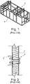
- Figure 1 shows a frame 5 of an enclosure for a turbomachine comprising a plurality of portions 6 (stringers).
- Figure 2 shows the fastening of a panel 7 with one portion 6 of the frame 5 (not shown in figure) via the bolt with nut 8. It is noted that the bolt with nut 8 passes through the panel 7 and through the portion 6. Therefore the panel 7 and the portion 6 of the frame 5 must be bored in advance.
- the main drawbacks of the fixing system according to the state of the art are the time required for the installation, the fact that holes need to be machined and reinforced in the panel and the impact on footprint of the enclosure.
- a fixing system a plurality of preliminary operations are required, like boring the panel to be installed, foreseen bushing inside the panels etcetera. This lend to a long time for production, installation, and to a long time for maintenance too, if dismounting a panel is required.
- the fastening of known fixing systems introduce a mechanical weakness, caused from the bores on the panel and on part of the frame. This further causes air leakage from inside the enclosure to the outside, therefore a robust and over dimensioned pressurizing system of the plant must be provided.
- special care needs to be taken in machining holes and installation of bushings to ensure integrity of the inner layers of the panel, avoiding contamination from the environment.
- the footprint of the enclosure is determined by the sum of the thickness of the frame and the thickness of the panels, which are installed over the stringers of the frame.
- An embodiment of the invention therefore relates to a fixing system comprising the features of claim 1.
- this fixing system allows the utilization of composite panels without the risk of damaging inner composite layers, avoiding possible contamination from the environment and minimizing pressure leakages.
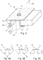
- Figure 3 shows an embodiment of a fixing system 10 for a panel 17 comprising an omega stringer 14 having a substantially omega-shaped cross-section.
- the omega stringer 14 comprises in turn:
- the omega stringer 14 is a portion of the frame of the turbomachine enclosure.
- the fixing system 10 further comprises a flat bar 15 longitudinally connected, namely along the direction concordant to the one indicated by the arrow 300, to the central portion 12 of the omega stringer 14.
- the omega stringer 14 and the flat bar 15 are directly connected and in contact each other.
- a sealing gasket 16 is arranged longitudinally onto the lateral foot portions 11, 13 of the omega stringer 14. For clarity reasons, just one side of the omega (the side of the foot portion 13) is shown accommodating a panel 17 and comprising the sealing gasket 16.
- the space 500 is defined between the outer portion 14a of the omega stringer 14, the gasket 16 and the flat bar 15. In the space 500, the panel 17 is firmly housed.
- FIGS. 3A to 3C show different embodiments relating to different possible arrangements of the sealing gasket 16.
- the fixing system 10 has two sealing gaskets 16, both arranged on foot portions 11, 13 of the omega 14.
- the fixing system 10 has two sealing gaskets 16, one arranged on the flat bar 15 and one arranged on one foot portion 13 of the omega stringer 14.
- the fixing system 10 has two sealing gaskets 16, both arranged on the flat bar 15.
- the height of the omega 14 stringer is selected so that when the panel 17 is clamped between the omega stringer 14 and the flat bar 15, the sealing gasket is compressed between the between panel 17 and the fixing system 10.
- Figure 4 shows the height of a omega stringer 14.
- the height 20 is defined as the distance between the upper surface 110, 130, considered with respect to a floor plane A, of the foot portions 11, 13 and the upper surface 12a of the central portion 12. Therefore, its height 20 is selected so that when a panel 17 is installed, the gasket 16 is compressed and the flat bar 15 is in abutment with the surface of the panel 17.
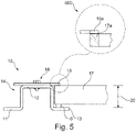
- Figure 5 shows a schematic view of the embodiment of figure 3 .
- the foot portions 11, 13 of this embodiment have a substantially rectangular cross section.
- the height 20 of the omega 14 allows compressing the gasket 16 of a compression rate of at least 30% of its height.
- the overlapping portions 15a and 17a between the flat bar 15 and the panel 17, namely the portion of flat bar in abutment with the portion of panel 17, is each time selected to ensure proper clamping of the panel 17 with the fixing system 10.
- the flat bar is connected to the central portion 12 of the omega 14 stringer by means of a plurality of connecting means 18.
- the thickness of omega stringer 14 is substantially equal to the thickness of the bar 15.
- such connecting means 18 are bolts with nuts. In one alternative embodiment, the connecting means 18 are rivets. In one alternative embodiment, the connecting means 18 are nails. In one alternative embodiment, the connecting means 18 are lever closures.
- the compressed gasket 16 brings about two effects.
- the first effect is to ensure a proper gastight.
- the second effect is to increase the frictional coefficient that the panel 17 experiences when a bending force is applied.
- FIG. 6 shows a further embodiment of a fixing system 10.
- the fixing system 10 of figure 6 is substantially similar to the one of figure 3 , therefore the same considerations may be done. Except for the omega stringer 14, which comprises a serif 11a, 13a on the foot portions 11, 13 configured to limit the compression of the sealing gasket 16 when the panel 17 is clamped between the omega stringer 14 and the flat bar 15.
- the omega stringer 14 which comprises a serif 11a, 13a on the foot portions 11, 13 configured to limit the compression of the sealing gasket 16 when the panel 17 is clamped between the omega stringer 14 and the flat bar 15.
- the serif may be defined on the flat bar 15.
- Figure 7 shows an embodiment of a fixing system 10 wherein the omega stringer 14 comprises serif 11a, 13a on its foot portions 11, 13.
- the serif 13a is on the terminal part of the foot portion 13; as well as the serif 11a is on the terminal part of the foot portion 11.
- the panel 17 is housed in the space 500 (see also figure 3 ).
- a portion of the upper surface 17a of the panel 17 is in abutment with a portion of the lower surface 15a of the flat bar 15.
- the serif 11a is in abutment with the lower surface 17b (opposite to the upper surface 17a) of the panel.
- the gasket 16 is compressed.
- Figure 7A shows a portion of omega 14 stringer with a serif 11a on its foot portion 11. It is noted that the overall height 20 of the omega 14 is defined in the same way of the omega 14 without serif of figure 4 . Furthermore, the omega 14 with the serif 11a has an operative height 21, wherein the panel may be housed. Such operative height 21 is defined as the distance between the upper surface of the serif 11a and the upper surface of the central portion 12. In this way, the compression of the gasket 16 is controllable.
- Figure 8 shows an embodiment of a turbomachine enclosure 100 comprising: a frame realized with fixing systems 10, of the type described above connected each other, a plurality of composite panels wherein the composite panels are clamped to the frame by means of the fixing systems 10 and the frame is arranged so to cover the turbomachine.
- the turbomachine enclosure described above is configured to be gastight.
Landscapes
- Engineering & Computer Science (AREA)
- General Engineering & Computer Science (AREA)
- Architecture (AREA)
- Physics & Mathematics (AREA)
- Mechanical Engineering (AREA)
- Combustion & Propulsion (AREA)
- Chemical & Material Sciences (AREA)
- Acoustics & Sound (AREA)
- Civil Engineering (AREA)
- Structural Engineering (AREA)
- Electromagnetism (AREA)
- Connection Of Plates (AREA)
- Soundproofing, Sound Blocking, And Sound Damping (AREA)
- Structures Of Non-Positive Displacement Pumps (AREA)
- Gasket Seals (AREA)
- Turbine Rotor Nozzle Sealing (AREA)
Description
- The subject matter of the present disclosure relates to a fixing system for panels, particularly for panels designed for noise absorption, and a turbomachine enclosure comprising such system.
-
WO 2013/092682 A2 discloses structurally integrated solar building elements (SISBEs). A profile is used to fill the gap between SISBEs and a screw or nail is used to fasten the profile to a support structure. - A turbomachine normally requires an enclosure configured to separate the outer environment from the installation room dedicated to the turbomachine. For safety reasons, the space defined by the enclosure, wherein the turbomachine is located, is in general pressurized (negative pressure is also used in some applications). The enclosure is therefore configured to be gas tight.
- The enclosure comprises a frame surrounding the turbomachine. A plurality of panels is installed on the frame to form the enclosure.
- In the current state of the art, the frame is a support for the panels, in particular each panel is fixed on a corresponding portion of the frame using fastening devices such as bolts with nuts, or the like. In detail, to ensure a proper fastening, the panel and the corresponding portion of frame are bored, to receive the fastening device and realize the fastening.
-
Figures 1 and 2 show this solution known from the state of the art. -
Figure 1 shows a frame 5 of an enclosure for a turbomachine comprising a plurality of portions 6 (stringers). -
Figure 2 shows the fastening of a panel 7 with oneportion 6 of the frame 5 (not shown in figure) via the bolt withnut 8. It is noted that the bolt withnut 8 passes through the panel 7 and through theportion 6. Therefore the panel 7 and theportion 6 of the frame 5 must be bored in advance. - The main drawbacks of the fixing system according to the state of the art are the time required for the installation, the fact that holes need to be machined and reinforced in the panel and the impact on footprint of the enclosure. Currently, to properly install a fixing system a plurality of preliminary operations are required, like boring the panel to be installed, foreseen bushing inside the panels etcetera. This lend to a long time for production, installation, and to a long time for maintenance too, if dismounting a panel is required.
- In addition, the fastening of known fixing systems introduce a mechanical weakness, caused from the bores on the panel and on part of the frame. This further causes air leakage from inside the enclosure to the outside, therefore a robust and over dimensioned pressurizing system of the plant must be provided. When dealing with composite sandwich panels, special care needs to be taken in machining holes and installation of bushings to ensure integrity of the inner layers of the panel, avoiding contamination from the environment. Furthermore, the footprint of the enclosure is determined by the sum of the thickness of the frame and the thickness of the panels, which are installed over the stringers of the frame.
- An embodiment of the invention therefore relates to a fixing system comprising the features of
claim 1. - Advantageously, with this fixing system the time for installation and maintenance is reduced, since a plug and play fixing system is achieved. Furthermore, this fixing system allows the utilization of composite panels without the risk of damaging inner composite layers, avoiding possible contamination from the environment and minimizing pressure leakages.
- Also advantageously, the footprint of the enclosure is significantly reduced, since with embodiments as described above, the panel is flush with the frame. Further details and specific embodiments will refer to the attached drawings, in which:
-
Figure 1 and 2 are schematic views of embodiments of a fixing system known from the prior art; -
Figure 3 is a perspective view of a first embodiment of a fixing system according to the present invention; - Figures from 3A to 3C show different embodiments of a fixing system not in accordance with the present invention;
-
Figure 4 is a schematic view of a component of a fixing system; -
Figure 5 is a schematic view of the embodiment offigure 3 ; -
Figure 6 is a perspective view of a second embodiment of a fixing system according to the present invention; -
Figure 7 is a schematic view of the embodiment offigure 6 ; -
Figure 7A shows a component of the embodiment offigure 6 ; -
Figure 8 is a perspective view of a turbomachine enclosure comprising a fixing system according to the present invention. - The following description of exemplary embodiments refers to the accompanying drawings. The same reference numbers in different drawings identify the same or similar elements. The following detailed description does not limit the invention. Instead, the scope of the invention is defined by the appended claims.
- Reference throughout the specification to "one embodiment" or "an embodiment" means that a particular feature, structure, or characteristic described in connection with an embodiment is included in at least one embodiment of the subject matter disclosed. Thus, the appearance of the phrases "in one embodiment" or "in an embodiment" in various places throughout the specification is not necessarily referring to the same embodiment. Further, the particular features, structures or characteristics may be combined in any suitable manner in one or more embodiments.
-
Figure 3 shows an embodiment of afixing system 10 for apanel 17 comprising anomega stringer 14 having a substantially omega-shaped cross-section. - The
omega stringer 14 comprises in turn: - a
central portion 12; - two lateral 11, 13 foot portions, in particular: a
first foot portion 11 and asecond foot portion 13 symmetric each other with respect to theaxis 200 of symmetry of theomega stringer 14. - In one embodiment, the
omega stringer 14 is a portion of the frame of the turbomachine enclosure. - The
fixing system 10 further comprises aflat bar 15 longitudinally connected, namely along the direction concordant to the one indicated by thearrow 300, to thecentral portion 12 of theomega stringer 14. The omega stringer 14 and theflat bar 15 are directly connected and in contact each other. A sealinggasket 16 is arranged longitudinally onto thelateral foot portions omega stringer 14. For clarity reasons, just one side of the omega (the side of the foot portion 13) is shown accommodating apanel 17 and comprising thesealing gasket 16. - As shown in
figure 3 , thespace 500 is defined between theouter portion 14a of theomega stringer 14, thegasket 16 and theflat bar 15. In thespace 500, thepanel 17 is firmly housed. - It is further appreciated that with this arrangement the
panel 17 is flush withomega stringer 14. - Figures from 3A to 3C show different embodiments relating to different possible arrangements of the sealing
gasket 16. - In
figure 3A , thefixing system 10 has twosealing gaskets 16, both arranged onfoot portions omega 14. - In
figure 3B , thefixing system 10 has twosealing gaskets 16, one arranged on theflat bar 15 and one arranged on onefoot portion 13 of theomega stringer 14. - In
figure 3C , thefixing system 10 has twosealing gaskets 16, both arranged on theflat bar 15. - The height of the
omega 14 stringer is selected so that when thepanel 17 is clamped between theomega stringer 14 and theflat bar 15, the sealing gasket is compressed between the betweenpanel 17 and thefixing system 10. -
Figure 4 shows the height of aomega stringer 14. In the embodiments described, theheight 20 is defined as the distance between theupper surface foot portions upper surface 12a of thecentral portion 12. Therefore, itsheight 20 is selected so that when apanel 17 is installed, thegasket 16 is compressed and theflat bar 15 is in abutment with the surface of thepanel 17. -
Figure 5 shows a schematic view of the embodiment offigure 3 . Thefoot portions height 20 of theomega 14 allows compressing thegasket 16 of a compression rate of at least 30% of its height. - Furthermore, as shown in the
enlarged portion 400, the overlappingportions flat bar 15 and thepanel 17, namely the portion of flat bar in abutment with the portion ofpanel 17, is each time selected to ensure proper clamping of thepanel 17 with the fixingsystem 10. - In one embodiment of the fixing
system 10, the flat bar is connected to thecentral portion 12 of theomega 14 stringer by means of a plurality of connectingmeans 18. - The thickness of
omega stringer 14 is substantially equal to the thickness of thebar 15. - In the embodiment shown in
figure 5 , such connectingmeans 18 are bolts with nuts. In one alternative embodiment, the connectingmeans 18 are rivets. In one alternative embodiment, the connectingmeans 18 are nails. In one alternative embodiment, the connectingmeans 18 are lever closures. - In use, the
compressed gasket 16 brings about two effects. The first effect is to ensure a proper gastight. The second effect is to increase the frictional coefficient that thepanel 17 experiences when a bending force is applied. - In this way, a proper gastight of the enclosure is ensured, as well as a good mechanical behavior.
-
Figure 6 shows a further embodiment of a fixingsystem 10. The fixingsystem 10 offigure 6 is substantially similar to the one offigure 3 , therefore the same considerations may be done. Except for theomega stringer 14, which comprises aserif foot portions gasket 16 when thepanel 17 is clamped between theomega stringer 14 and theflat bar 15. - In one alternative embodiment, the serif may be defined on the
flat bar 15. -
Figure 7 shows an embodiment of a fixingsystem 10 wherein theomega stringer 14 comprisesserif foot portions serif 13a is on the terminal part of thefoot portion 13; as well as theserif 11a is on the terminal part of thefoot portion 11. In use, thepanel 17 is housed in the space 500 (see alsofigure 3 ). A portion of theupper surface 17a of thepanel 17 is in abutment with a portion of thelower surface 15a of theflat bar 15. Theserif 11a is in abutment with thelower surface 17b (opposite to theupper surface 17a) of the panel. Thegasket 16 is compressed. -
Figure 7A shows a portion ofomega 14 stringer with aserif 11a on itsfoot portion 11. It is noted that theoverall height 20 of theomega 14 is defined in the same way of theomega 14 without serif offigure 4 . Furthermore, theomega 14 with theserif 11a has anoperative height 21, wherein the panel may be housed. Suchoperative height 21 is defined as the distance between the upper surface of theserif 11a and the upper surface of thecentral portion 12. In this way, the compression of thegasket 16 is controllable. -
Figure 8 shows an embodiment of aturbomachine enclosure 100 comprising:
a frame realized with fixingsystems 10, of the type described above connected each other, a plurality of composite panels wherein the composite panels are clamped to the frame by means of the fixingsystems 10 and the frame is arranged so to cover the turbomachine. - In one embodiment, the turbomachine enclosure described above is configured to be gastight.
Claims (10)
- A fixing system (10) for a composite panel (17), the fixing system comprising:an omega stringer (14) having a substantially omega-shaped cross-section, wherein the omega stringer comprises a central portion (12) and two lateral (11, 13) foot portions;characterized by a flat bar (15) longitudinally directly connected to the central portion (12) of the omega stringer (14); a sealing gasket (16) arranged longitudinally onto the lateral (11, 13) foot portions of the omega stringer (14) or onto the flat bar (15);wherein the height (20) of the omega stringer (14) is selected so that, in use, when a panel (17) is clamped between the omega stringer (14) and the flat bar (15), the sealing gasket (16) is compressed between the panel (17) and the fixing system (10); anda serif (11a, 13a) arranged on the foot portions (11, 13) of the omega stringer (14) or onto the flat bar (15), the serif (11a, 13a) being configured to limit the compression of the sealing gasket (16) when the panel (17) is clamped between the omega stringer (14) and the flat bar (15).
- The fixing system (10) according to claim 1, wherein, in use, the sealing gasket (16) is compressed with a compression rate of at least 30% of the sealing gasket height.
- The fixing system (10) according to any of the preceding claims, wherein the flat bar (15) is directly connected to the central portion (12) of the omega stringer (14) by means of a plurality of connecting means (18).
- The fixing system (10) according to claim 3, wherein the plurality of connecting means (18) are bolts with nuts, rivets, nails or lever closure.
- The fixing system (10) according to any of the preceding claims, wherein the flat bar (15) has a width higher than the width of the central portion of the omega stringer.
- The fixing system (10) according to claim 5, wherein the flat bar (15) has a width substantially equal to the width of the omega stringer (14).
- The fixing system (10) according to any of the preceding claims, wherein the thickness of omega stringer (14) is substantially equal to the thickness of the bar (15).
- A turbomachine enclosure (100) comprising:a frame realized with fixing systems (10) according to one or more of the preceding claims connected each other;a plurality of panels (17);wherein the panels (17) are clamped to the frame by means of said fixing systems (10) and the frame is arranged to cover the turbomachine.
- The turbomachine enclosure according to claim 8 wherein said panels (17) are noise absorption panels.
- The turbomachine enclosure according to claim 8 or claim 9, wherein the enclosure is configured to be gastight.
Applications Claiming Priority (2)
| Application Number | Priority Date | Filing Date | Title |
|---|---|---|---|
| ITUB2016A000720A ITUB20160720A1 (en) | 2016-02-12 | 2016-02-12 | Fixing system for panels and turbomachine enclosure comprising such system |
| PCT/EP2017/052518 WO2017137345A1 (en) | 2016-02-12 | 2017-02-06 | Fixing system for panels and turbomachine enclosure comprising such system |
Publications (2)
| Publication Number | Publication Date |
|---|---|
| EP3414432A1 EP3414432A1 (en) | 2018-12-19 |
| EP3414432B1 true EP3414432B1 (en) | 2022-03-30 |
Family
ID=55861055
Family Applications (1)
| Application Number | Title | Priority Date | Filing Date |
|---|---|---|---|
| EP17703963.3A Active EP3414432B1 (en) | 2016-02-12 | 2017-02-06 | Fixing system for panels and turbomachine enclosure comprising such system |
Country Status (6)
| Country | Link |
|---|---|
| US (1) | US11346492B2 (en) |
| EP (1) | EP3414432B1 (en) |
| JP (1) | JP7126449B2 (en) |
| CN (1) | CN108603416B (en) |
| IT (1) | ITUB20160720A1 (en) |
| WO (1) | WO2017137345A1 (en) |
Families Citing this family (2)
| Publication number | Priority date | Publication date | Assignee | Title |
|---|---|---|---|---|
| CN210467924U (en) * | 2019-09-17 | 2020-05-05 | 宁德时代新能源科技股份有限公司 | A battery pack and vehicle |
| KR102442650B1 (en) * | 2021-01-28 | 2022-09-13 | 박준형 | hanging support construction between big SCR cartridge and supporting frame for dust collector with dry reaction of combustion furnace |
Citations (1)
| Publication number | Priority date | Publication date | Assignee | Title |
|---|---|---|---|---|
| US20100236183A1 (en) * | 2009-03-20 | 2010-09-23 | Northern States Metals Company | Support System for Solar Panels |
Family Cites Families (25)
| Publication number | Priority date | Publication date | Assignee | Title |
|---|---|---|---|---|
| US2809726A (en) * | 1954-04-13 | 1957-10-15 | Reynolds Metals Co | Securing means for curtain wall panels |
| US2927665A (en) * | 1955-02-07 | 1960-03-08 | Chicago Metal Mfg Co | Prefabricated sealed building construction |
| US3485405A (en) * | 1968-07-05 | 1969-12-23 | Us Plywood Champ Papers Inc | Frame-structure for container |
| US4028856A (en) * | 1976-01-26 | 1977-06-14 | Mallyclad Corporation | Cover wall construction |
| US4158938A (en) * | 1977-10-05 | 1979-06-26 | Owens-Corning Fiberglas Corporation | Foamed plastic panel connecting means and wall structure |
| FR2461069A1 (en) * | 1979-07-13 | 1981-01-30 | Isotecnica Spa | Junction channel anchor for facade insulating panels - has shaped profile to lock panels filled with insulating foam |
| FR2468782A1 (en) * | 1979-08-14 | 1981-05-08 | Quatre Chemins Entreprise | Water-tight joint for flat panels - has continuous internal section with retaining nuts held by spring clips |
| US4300323A (en) * | 1980-03-17 | 1981-11-17 | Owens-Corning Fiberglas Corporation | Foamed plastic panel connecting means |
| JPS59138643A (en) * | 1983-01-26 | 1984-08-09 | 松下電工株式会社 | Bathroom unit |
| JPS59185787U (en) * | 1983-05-30 | 1984-12-10 | 株式会社日立製作所 | magnetic disk device |
| US4794206A (en) * | 1986-11-20 | 1988-12-27 | Industrial Acoustics Company, Inc. | RF shielded and acoustic room |
| FR2733261B1 (en) * | 1995-04-19 | 1997-06-13 | Eurosilence | SOUND INSULATION PANEL |
| FR2749620A1 (en) * | 1996-06-07 | 1997-12-12 | Equip Routier Sn | Shock absorbing panel mounting for roadways |
| JP4711046B2 (en) * | 2004-11-30 | 2011-06-29 | Nok株式会社 | Sealing structure |
| US20080127577A1 (en) | 2006-12-04 | 2008-06-05 | Pius Elmiger | Connecting device and method for connecting two wall elements of an elevator cage |
| DE102008009703A1 (en) * | 2008-02-18 | 2009-08-20 | Vm Edelstahltechnik Gmbh | Retaining device i.e. laminate clamp, for entrapment of solar modules, has compressable block provided between supporting elements, where height of block is larger than distance between traversing bars, in non-compressed condition |
| PL214418B1 (en) * | 2008-03-10 | 2013-07-31 | Fakro Pp Spolka Z Ograniczona Odpowiedzialnoscia | Shield strip with a mounting |
| DE102008045414B4 (en) * | 2008-09-02 | 2012-04-26 | Sfs Intec Holding Ag | Fastener and system for securing a component |
| DE102009039791A1 (en) * | 2009-09-02 | 2011-03-17 | Adensis Gmbh | Lower module terminal part for two-piece modular terminal for photovoltaic module to be mounted in assembly robot, has flat, rectangular-shaped lower side and two bars run parallel to each other from side facing lower side |
| US8733027B1 (en) * | 2009-11-06 | 2014-05-27 | Innovative Medical Products Inc. | Method and apparatus for attaching a solar panel to a roof |
| DE102011079057A1 (en) * | 2011-07-13 | 2013-01-17 | Reisser Schraubentechnik Gmbh | Screw for fastening profile at base profile at e.g. rooftop, has threaded section originating from end of shaft, and collar turned toward screw end at end of threaded section, where diameter of section is larger than diameter of thread |
| WO2013092682A2 (en) * | 2011-12-22 | 2013-06-27 | Designergy Sa | Structurally integrated solar building element |
| FR3001199B1 (en) * | 2013-01-23 | 2016-07-15 | Snecma | MOTOR COVER INCORPORATING AN EQUIPMENT VENTILATION CIRCUIT |
| CN103195511B (en) * | 2013-04-03 | 2015-05-06 | 杭州天桥电器有限公司 | Assembling type steam turbine casing |
| US9068764B2 (en) * | 2013-04-10 | 2015-06-30 | Stion Corporation | Method and apparatus for clamping frameless thin-film solar module |
-
2016
- 2016-02-12 IT ITUB2016A000720A patent/ITUB20160720A1/en unknown
-
2017
- 2017-02-06 WO PCT/EP2017/052518 patent/WO2017137345A1/en not_active Ceased
- 2017-02-06 JP JP2018541418A patent/JP7126449B2/en active Active
- 2017-02-06 EP EP17703963.3A patent/EP3414432B1/en active Active
- 2017-02-06 CN CN201780010819.8A patent/CN108603416B/en active Active
- 2017-02-06 US US16/077,137 patent/US11346492B2/en active Active
Patent Citations (1)
| Publication number | Priority date | Publication date | Assignee | Title |
|---|---|---|---|---|
| US20100236183A1 (en) * | 2009-03-20 | 2010-09-23 | Northern States Metals Company | Support System for Solar Panels |
Also Published As
| Publication number | Publication date |
|---|---|
| US11346492B2 (en) | 2022-05-31 |
| CN108603416A (en) | 2018-09-28 |
| EP3414432A1 (en) | 2018-12-19 |
| WO2017137345A1 (en) | 2017-08-17 |
| CN108603416B (en) | 2022-02-08 |
| JP2019512067A (en) | 2019-05-09 |
| JP7126449B2 (en) | 2022-08-26 |
| ITUB20160720A1 (en) | 2017-08-12 |
| CA3013529A1 (en) | 2017-08-17 |
| US20190032839A1 (en) | 2019-01-31 |
Similar Documents
| Publication | Publication Date | Title |
|---|---|---|
| EP1196325B2 (en) | Monolithic structure with redundant load paths | |
| US8714633B2 (en) | Honeycomb-structured floor panel for a vehicle incorporating a fastener element | |
| WO1982000324A1 (en) | Aircraft floor panel installation system | |
| US20130181092A1 (en) | Device and method for assembling two sections of aircraft fuselage | |
| US20120187247A1 (en) | Manhole assembly in the lower skin of an aircraft wing made of a composite material | |
| WO2009083575A3 (en) | Optimized aircraft manhole | |
| EP3392114B1 (en) | Vehicle door for railway vehicle and railway vehicle comprising the vehicle door | |
| US11325717B2 (en) | Aircraft nacelle including a link between a conduit of an air inlet and a conduit of an engine | |
| JP6742411B2 (en) | Solar cell assembly and solar cell module | |
| US11346492B2 (en) | Fixing system for panels and turbomachine enclosure comprising such system | |
| US20210053797A1 (en) | Guide rail bracket assembly | |
| KR20170009042A (en) | Double metallic barrier apparatus for cargo containment system of lng carrier and the manufacturing method thereof | |
| CA3013529C (en) | Fixing system for panels and turbomachine enclosure comprising such system | |
| US20180362142A1 (en) | Panel for an aircraft structure | |
| CN102674116B (en) | Elevator cabinet | |
| JP2013019111A (en) | Hood box for attaching building structure for aggregated piping/wiring | |
| US10843785B2 (en) | Pressure bulkhead | |
| US12612149B2 (en) | Decompression panel for an aircraft and an internal wall of an aircraft having such a decompression panel | |
| CN217301795U (en) | Auxiliary opening device for emergency drainage pneumatic valve | |
| KR20160024057A (en) | Zig apparatus for setting bottom insulation board of cargo corner part | |
| US20080135682A1 (en) | Arrangement And Method For Installing A Component In An Aircraft | |
| JP6049524B2 (en) | Seismic isolation device | |
| CN110962872A (en) | Side wall panel assembly for rail vehicle and rail vehicle having the same | |
| KR20230145896A (en) | Fire protection curtain wall structure | |
| JP3156567U (en) | Bolt hole repair structure |
Legal Events
| Date | Code | Title | Description |
|---|---|---|---|
| STAA | Information on the status of an ep patent application or granted ep patent |
Free format text: STATUS: UNKNOWN |
|
| STAA | Information on the status of an ep patent application or granted ep patent |
Free format text: STATUS: THE INTERNATIONAL PUBLICATION HAS BEEN MADE |
|
| PUAI | Public reference made under article 153(3) epc to a published international application that has entered the european phase |
Free format text: ORIGINAL CODE: 0009012 |
|
| STAA | Information on the status of an ep patent application or granted ep patent |
Free format text: STATUS: REQUEST FOR EXAMINATION WAS MADE |
|
| 17P | Request for examination filed |
Effective date: 20180912 |
|
| AK | Designated contracting states |
Kind code of ref document: A1 Designated state(s): AL AT BE BG CH CY CZ DE DK EE ES FI FR GB GR HR HU IE IS IT LI LT LU LV MC MK MT NL NO PL PT RO RS SE SI SK SM TR |
|
| AX | Request for extension of the european patent |
Extension state: BA ME |
|
| DAV | Request for validation of the european patent (deleted) | ||
| DAX | Request for extension of the european patent (deleted) | ||
| STAA | Information on the status of an ep patent application or granted ep patent |
Free format text: STATUS: EXAMINATION IS IN PROGRESS |
|
| 17Q | First examination report despatched |
Effective date: 20191210 |
|
| REG | Reference to a national code |
Ref country code: DE Ref legal event code: R079 Ref document number: 602017055159 Country of ref document: DE Free format text: PREVIOUS MAIN CLASS: F01D0025140000 Ipc: F01D0025280000 |
|
| GRAP | Despatch of communication of intention to grant a patent |
Free format text: ORIGINAL CODE: EPIDOSNIGR1 |
|
| STAA | Information on the status of an ep patent application or granted ep patent |
Free format text: STATUS: GRANT OF PATENT IS INTENDED |
|
| RIC1 | Information provided on ipc code assigned before grant |
Ipc: F02C 7/24 20060101ALI20210819BHEP Ipc: F16B 5/00 20060101ALI20210819BHEP Ipc: F01D 25/28 20060101AFI20210819BHEP |
|
| INTG | Intention to grant announced |
Effective date: 20210906 |
|
| GRAS | Grant fee paid |
Free format text: ORIGINAL CODE: EPIDOSNIGR3 |
|
| GRAA | (expected) grant |
Free format text: ORIGINAL CODE: 0009210 |
|
| STAA | Information on the status of an ep patent application or granted ep patent |
Free format text: STATUS: THE PATENT HAS BEEN GRANTED |
|
| AK | Designated contracting states |
Kind code of ref document: B1 Designated state(s): AL AT BE BG CH CY CZ DE DK EE ES FI FR GB GR HR HU IE IS IT LI LT LU LV MC MK MT NL NO PL PT RO RS SE SI SK SM TR |
|
| REG | Reference to a national code |
Ref country code: GB Ref legal event code: FG4D |
|
| REG | Reference to a national code |
Ref country code: CH Ref legal event code: EP |
|
| REG | Reference to a national code |
Ref country code: AT Ref legal event code: REF Ref document number: 1479376 Country of ref document: AT Kind code of ref document: T Effective date: 20220415 |
|
| REG | Reference to a national code |
Ref country code: DE Ref legal event code: R096 Ref document number: 602017055159 Country of ref document: DE |
|
| REG | Reference to a national code |
Ref country code: SE Ref legal event code: TRGR |
|
| REG | Reference to a national code |
Ref country code: IE Ref legal event code: FG4D |
|
| REG | Reference to a national code |
Ref country code: NO Ref legal event code: T2 Effective date: 20220330 |
|
| REG | Reference to a national code |
Ref country code: LT Ref legal event code: MG9D |
|
| PG25 | Lapsed in a contracting state [announced via postgrant information from national office to epo] |
Ref country code: RS Free format text: LAPSE BECAUSE OF FAILURE TO SUBMIT A TRANSLATION OF THE DESCRIPTION OR TO PAY THE FEE WITHIN THE PRESCRIBED TIME-LIMIT Effective date: 20220330 Ref country code: LT Free format text: LAPSE BECAUSE OF FAILURE TO SUBMIT A TRANSLATION OF THE DESCRIPTION OR TO PAY THE FEE WITHIN THE PRESCRIBED TIME-LIMIT Effective date: 20220330 Ref country code: HR Free format text: LAPSE BECAUSE OF FAILURE TO SUBMIT A TRANSLATION OF THE DESCRIPTION OR TO PAY THE FEE WITHIN THE PRESCRIBED TIME-LIMIT Effective date: 20220330 Ref country code: BG Free format text: LAPSE BECAUSE OF FAILURE TO SUBMIT A TRANSLATION OF THE DESCRIPTION OR TO PAY THE FEE WITHIN THE PRESCRIBED TIME-LIMIT Effective date: 20220630 |
|
| REG | Reference to a national code |
Ref country code: NL Ref legal event code: MP Effective date: 20220330 |
|
| REG | Reference to a national code |
Ref country code: AT Ref legal event code: MK05 Ref document number: 1479376 Country of ref document: AT Kind code of ref document: T Effective date: 20220330 |
|
| PG25 | Lapsed in a contracting state [announced via postgrant information from national office to epo] |
Ref country code: LV Free format text: LAPSE BECAUSE OF FAILURE TO SUBMIT A TRANSLATION OF THE DESCRIPTION OR TO PAY THE FEE WITHIN THE PRESCRIBED TIME-LIMIT Effective date: 20220330 Ref country code: GR Free format text: LAPSE BECAUSE OF FAILURE TO SUBMIT A TRANSLATION OF THE DESCRIPTION OR TO PAY THE FEE WITHIN THE PRESCRIBED TIME-LIMIT Effective date: 20220701 Ref country code: FI Free format text: LAPSE BECAUSE OF FAILURE TO SUBMIT A TRANSLATION OF THE DESCRIPTION OR TO PAY THE FEE WITHIN THE PRESCRIBED TIME-LIMIT Effective date: 20220330 |
|
| PG25 | Lapsed in a contracting state [announced via postgrant information from national office to epo] |
Ref country code: NL Free format text: LAPSE BECAUSE OF FAILURE TO SUBMIT A TRANSLATION OF THE DESCRIPTION OR TO PAY THE FEE WITHIN THE PRESCRIBED TIME-LIMIT Effective date: 20220330 |
|
| PG25 | Lapsed in a contracting state [announced via postgrant information from national office to epo] |
Ref country code: SM Free format text: LAPSE BECAUSE OF FAILURE TO SUBMIT A TRANSLATION OF THE DESCRIPTION OR TO PAY THE FEE WITHIN THE PRESCRIBED TIME-LIMIT Effective date: 20220330 Ref country code: SK Free format text: LAPSE BECAUSE OF FAILURE TO SUBMIT A TRANSLATION OF THE DESCRIPTION OR TO PAY THE FEE WITHIN THE PRESCRIBED TIME-LIMIT Effective date: 20220330 Ref country code: RO Free format text: LAPSE BECAUSE OF FAILURE TO SUBMIT A TRANSLATION OF THE DESCRIPTION OR TO PAY THE FEE WITHIN THE PRESCRIBED TIME-LIMIT Effective date: 20220330 Ref country code: PT Free format text: LAPSE BECAUSE OF FAILURE TO SUBMIT A TRANSLATION OF THE DESCRIPTION OR TO PAY THE FEE WITHIN THE PRESCRIBED TIME-LIMIT Effective date: 20220801 Ref country code: ES Free format text: LAPSE BECAUSE OF FAILURE TO SUBMIT A TRANSLATION OF THE DESCRIPTION OR TO PAY THE FEE WITHIN THE PRESCRIBED TIME-LIMIT Effective date: 20220330 Ref country code: EE Free format text: LAPSE BECAUSE OF FAILURE TO SUBMIT A TRANSLATION OF THE DESCRIPTION OR TO PAY THE FEE WITHIN THE PRESCRIBED TIME-LIMIT Effective date: 20220330 Ref country code: CZ Free format text: LAPSE BECAUSE OF FAILURE TO SUBMIT A TRANSLATION OF THE DESCRIPTION OR TO PAY THE FEE WITHIN THE PRESCRIBED TIME-LIMIT Effective date: 20220330 Ref country code: AT Free format text: LAPSE BECAUSE OF FAILURE TO SUBMIT A TRANSLATION OF THE DESCRIPTION OR TO PAY THE FEE WITHIN THE PRESCRIBED TIME-LIMIT Effective date: 20220330 |
|
| PG25 | Lapsed in a contracting state [announced via postgrant information from national office to epo] |
Ref country code: PL Free format text: LAPSE BECAUSE OF FAILURE TO SUBMIT A TRANSLATION OF THE DESCRIPTION OR TO PAY THE FEE WITHIN THE PRESCRIBED TIME-LIMIT Effective date: 20220330 Ref country code: IS Free format text: LAPSE BECAUSE OF FAILURE TO SUBMIT A TRANSLATION OF THE DESCRIPTION OR TO PAY THE FEE WITHIN THE PRESCRIBED TIME-LIMIT Effective date: 20220730 Ref country code: AL Free format text: LAPSE BECAUSE OF FAILURE TO SUBMIT A TRANSLATION OF THE DESCRIPTION OR TO PAY THE FEE WITHIN THE PRESCRIBED TIME-LIMIT Effective date: 20220330 |
|
| REG | Reference to a national code |
Ref country code: DE Ref legal event code: R097 Ref document number: 602017055159 Country of ref document: DE |
|
| PG25 | Lapsed in a contracting state [announced via postgrant information from national office to epo] |
Ref country code: DK Free format text: LAPSE BECAUSE OF FAILURE TO SUBMIT A TRANSLATION OF THE DESCRIPTION OR TO PAY THE FEE WITHIN THE PRESCRIBED TIME-LIMIT Effective date: 20220330 |
|
| PLBE | No opposition filed within time limit |
Free format text: ORIGINAL CODE: 0009261 |
|
| STAA | Information on the status of an ep patent application or granted ep patent |
Free format text: STATUS: NO OPPOSITION FILED WITHIN TIME LIMIT |
|
| 26N | No opposition filed |
Effective date: 20230103 |
|
| PG25 | Lapsed in a contracting state [announced via postgrant information from national office to epo] |
Ref country code: SI Free format text: LAPSE BECAUSE OF FAILURE TO SUBMIT A TRANSLATION OF THE DESCRIPTION OR TO PAY THE FEE WITHIN THE PRESCRIBED TIME-LIMIT Effective date: 20220330 |
|
| P01 | Opt-out of the competence of the unified patent court (upc) registered |
Effective date: 20230526 |
|
| PG25 | Lapsed in a contracting state [announced via postgrant information from national office to epo] |
Ref country code: IT Free format text: LAPSE BECAUSE OF FAILURE TO SUBMIT A TRANSLATION OF THE DESCRIPTION OR TO PAY THE FEE WITHIN THE PRESCRIBED TIME-LIMIT Effective date: 20220330 |
|
| PG25 | Lapsed in a contracting state [announced via postgrant information from national office to epo] |
Ref country code: MC Free format text: LAPSE BECAUSE OF FAILURE TO SUBMIT A TRANSLATION OF THE DESCRIPTION OR TO PAY THE FEE WITHIN THE PRESCRIBED TIME-LIMIT Effective date: 20220330 |
|
| REG | Reference to a national code |
Ref country code: BE Ref legal event code: MM Effective date: 20230228 |
|
| PG25 | Lapsed in a contracting state [announced via postgrant information from national office to epo] |
Ref country code: LU Free format text: LAPSE BECAUSE OF NON-PAYMENT OF DUE FEES Effective date: 20230206 |
|
| REG | Reference to a national code |
Ref country code: IE Ref legal event code: MM4A |
|
| PG25 | Lapsed in a contracting state [announced via postgrant information from national office to epo] |
Ref country code: IE Free format text: LAPSE BECAUSE OF NON-PAYMENT OF DUE FEES Effective date: 20230206 Ref country code: FR Free format text: LAPSE BECAUSE OF NON-PAYMENT OF DUE FEES Effective date: 20230228 |
|
| PG25 | Lapsed in a contracting state [announced via postgrant information from national office to epo] |
Ref country code: BE Free format text: LAPSE BECAUSE OF NON-PAYMENT OF DUE FEES Effective date: 20230228 |
|
| PG25 | Lapsed in a contracting state [announced via postgrant information from national office to epo] |
Ref country code: CY Free format text: LAPSE BECAUSE OF FAILURE TO SUBMIT A TRANSLATION OF THE DESCRIPTION OR TO PAY THE FEE WITHIN THE PRESCRIBED TIME-LIMIT; INVALID AB INITIO Effective date: 20170206 |
|
| PG25 | Lapsed in a contracting state [announced via postgrant information from national office to epo] |
Ref country code: HU Free format text: LAPSE BECAUSE OF FAILURE TO SUBMIT A TRANSLATION OF THE DESCRIPTION OR TO PAY THE FEE WITHIN THE PRESCRIBED TIME-LIMIT; INVALID AB INITIO Effective date: 20170206 |
|
| PG25 | Lapsed in a contracting state [announced via postgrant information from national office to epo] |
Ref country code: TR Free format text: LAPSE BECAUSE OF FAILURE TO SUBMIT A TRANSLATION OF THE DESCRIPTION OR TO PAY THE FEE WITHIN THE PRESCRIBED TIME-LIMIT Effective date: 20220330 |
|
| REG | Reference to a national code |
Ref country code: CH Ref legal event code: U11 Free format text: ST27 STATUS EVENT CODE: U-0-0-U10-U11 (AS PROVIDED BY THE NATIONAL OFFICE) Effective date: 20260301 |
|
| PGFP | Annual fee paid to national office [announced via postgrant information from national office to epo] |
Ref country code: SE Payment date: 20260121 Year of fee payment: 10 |
|
| PGFP | Annual fee paid to national office [announced via postgrant information from national office to epo] |
Ref country code: GB Payment date: 20260122 Year of fee payment: 10 |
|
| PGFP | Annual fee paid to national office [announced via postgrant information from national office to epo] |
Ref country code: DE Payment date: 20260121 Year of fee payment: 10 Ref country code: NO Payment date: 20260123 Year of fee payment: 10 |
|
| PGFP | Annual fee paid to national office [announced via postgrant information from national office to epo] |
Ref country code: CH Payment date: 20260301 Year of fee payment: 10 |