EP3414151B1 - Gearbox - Google Patents
Gearbox Download PDFInfo
- Publication number
- EP3414151B1 EP3414151B1 EP17705093.7A EP17705093A EP3414151B1 EP 3414151 B1 EP3414151 B1 EP 3414151B1 EP 17705093 A EP17705093 A EP 17705093A EP 3414151 B1 EP3414151 B1 EP 3414151B1
- Authority
- EP
- European Patent Office
- Prior art keywords
- bearing
- crank
- swing arm
- support plate
- arm
- Prior art date
- Legal status (The legal status is an assumption and is not a legal conclusion. Google has not performed a legal analysis and makes no representation as to the accuracy of the status listed.)
- Active
Links
- 230000005540 biological transmission Effects 0.000 claims description 43
- 230000008878 coupling Effects 0.000 claims description 4
- 238000010168 coupling process Methods 0.000 claims description 4
- 238000005859 coupling reaction Methods 0.000 claims description 4
- 230000000295 complement effect Effects 0.000 description 2
- 238000010276 construction Methods 0.000 description 2
- 238000009434 installation Methods 0.000 description 2
- 230000001133 acceleration Effects 0.000 description 1
- 230000015572 biosynthetic process Effects 0.000 description 1
- 239000007822 coupling agent Substances 0.000 description 1
- 230000000694 effects Effects 0.000 description 1
- 238000005516 engineering process Methods 0.000 description 1
- 230000002349 favourable effect Effects 0.000 description 1
- 230000001141 propulsive effect Effects 0.000 description 1
- 238000007789 sealing Methods 0.000 description 1
- 238000007493 shaping process Methods 0.000 description 1
- 230000000007 visual effect Effects 0.000 description 1
- XLYOFNOQVPJJNP-UHFFFAOYSA-N water Substances O XLYOFNOQVPJJNP-UHFFFAOYSA-N 0.000 description 1
Images


Classifications
-
- B—PERFORMING OPERATIONS; TRANSPORTING
- B62—LAND VEHICLES FOR TRAVELLING OTHERWISE THAN ON RAILS
- B62M—RIDER PROPULSION OF WHEELED VEHICLES OR SLEDGES; POWERED PROPULSION OF SLEDGES OR SINGLE-TRACK CYCLES; TRANSMISSIONS SPECIALLY ADAPTED FOR SUCH VEHICLES
- B62M3/00—Construction of cranks operated by hand or foot
- B62M3/06—Construction of cranks operated by hand or foot with elliptical or other non-circular rotary movement
-
- B—PERFORMING OPERATIONS; TRANSPORTING
- B62—LAND VEHICLES FOR TRAVELLING OTHERWISE THAN ON RAILS
- B62M—RIDER PROPULSION OF WHEELED VEHICLES OR SLEDGES; POWERED PROPULSION OF SLEDGES OR SINGLE-TRACK CYCLES; TRANSMISSIONS SPECIALLY ADAPTED FOR SUCH VEHICLES
- B62M11/00—Transmissions characterised by the use of interengaging toothed wheels or frictionally-engaging wheels
- B62M11/02—Transmissions characterised by the use of interengaging toothed wheels or frictionally-engaging wheels of unchangeable ratio
-
- B—PERFORMING OPERATIONS; TRANSPORTING
- B62—LAND VEHICLES FOR TRAVELLING OTHERWISE THAN ON RAILS
- B62M—RIDER PROPULSION OF WHEELED VEHICLES OR SLEDGES; POWERED PROPULSION OF SLEDGES OR SINGLE-TRACK CYCLES; TRANSMISSIONS SPECIALLY ADAPTED FOR SUCH VEHICLES
- B62M11/00—Transmissions characterised by the use of interengaging toothed wheels or frictionally-engaging wheels
- B62M11/04—Transmissions characterised by the use of interengaging toothed wheels or frictionally-engaging wheels of changeable ratio
- B62M11/14—Transmissions characterised by the use of interengaging toothed wheels or frictionally-engaging wheels of changeable ratio with planetary gears
-
- B—PERFORMING OPERATIONS; TRANSPORTING
- B62—LAND VEHICLES FOR TRAVELLING OTHERWISE THAN ON RAILS
- B62M—RIDER PROPULSION OF WHEELED VEHICLES OR SLEDGES; POWERED PROPULSION OF SLEDGES OR SINGLE-TRACK CYCLES; TRANSMISSIONS SPECIALLY ADAPTED FOR SUCH VEHICLES
- B62M9/00—Transmissions characterised by use of an endless chain, belt, or the like
- B62M9/04—Transmissions characterised by use of an endless chain, belt, or the like of changeable ratio
- B62M9/06—Transmissions characterised by use of an endless chain, belt, or the like of changeable ratio using a single chain, belt, or the like
- B62M9/08—Transmissions characterised by use of an endless chain, belt, or the like of changeable ratio using a single chain, belt, or the like involving eccentrically- mounted or elliptically-shaped driving or driven wheel; with expansible driving or driven wheel
-
- F—MECHANICAL ENGINEERING; LIGHTING; HEATING; WEAPONS; BLASTING
- F16—ENGINEERING ELEMENTS AND UNITS; GENERAL MEASURES FOR PRODUCING AND MAINTAINING EFFECTIVE FUNCTIONING OF MACHINES OR INSTALLATIONS; THERMAL INSULATION IN GENERAL
- F16H—GEARING
- F16H1/00—Toothed gearings for conveying rotary motion
- F16H1/28—Toothed gearings for conveying rotary motion with gears having orbital motion
-
- F—MECHANICAL ENGINEERING; LIGHTING; HEATING; WEAPONS; BLASTING
- F16—ENGINEERING ELEMENTS AND UNITS; GENERAL MEASURES FOR PRODUCING AND MAINTAINING EFFECTIVE FUNCTIONING OF MACHINES OR INSTALLATIONS; THERMAL INSULATION IN GENERAL
- F16H—GEARING
- F16H35/00—Gearings or mechanisms with other special functional features
-
- F—MECHANICAL ENGINEERING; LIGHTING; HEATING; WEAPONS; BLASTING
- F16—ENGINEERING ELEMENTS AND UNITS; GENERAL MEASURES FOR PRODUCING AND MAINTAINING EFFECTIVE FUNCTIONING OF MACHINES OR INSTALLATIONS; THERMAL INSULATION IN GENERAL
- F16H—GEARING
- F16H55/00—Elements with teeth or friction surfaces for conveying motion; Worms, pulleys or sheaves for gearing mechanisms
- F16H55/02—Toothed members; Worms
- F16H55/30—Chain-wheels
-
- F—MECHANICAL ENGINEERING; LIGHTING; HEATING; WEAPONS; BLASTING
- F16—ENGINEERING ELEMENTS AND UNITS; GENERAL MEASURES FOR PRODUCING AND MAINTAINING EFFECTIVE FUNCTIONING OF MACHINES OR INSTALLATIONS; THERMAL INSULATION IN GENERAL
- F16H—GEARING
- F16H35/00—Gearings or mechanisms with other special functional features
- F16H2035/003—Gearings comprising pulleys or toothed members of non-circular shape, e.g. elliptical gears
Definitions
- the invention relates to a transmission according to the features in the preamble of claim 1.
- Such gears can be installed in particular in bicycles and ensure an increase in torque by the force introduced by the cyclist.
- the housing of the transmission is adapted to a frame component and the force transmission means, for example a ring gear, transmits the torque generated by the cyclist to the rear wheel via a chain.
- the transmission according to the invention can also be provided, for example, on wind turbines with vertical axes of rotation.
- the DE 295 00 144 U1 discloses a drive device which is particularly suitable for bicycles and which cooperates on one side with one of the two pedal cranks and is intended to enable a dead center-free drive with the same movement on both sides, in each case only offset by half a period.
- a disadvantage of this device has been found that the torque curve and thus the efficiency is hardly improved.
- the Q-factor denotes the lateral distance between the outer surfaces of the two cranks.
- the object of the invention was to provide a transmission which has dimensions which are as compact as possible in the axial direction of the central shaft and whose rotating drive crank is guided with as little play as possible.
- a pendulum arm is understood to be a rigid component which, starting from a central position, swivels with one end in two directions around a bearing point. This has the advantage that there is no need for kinematically optimal rotary thrust joints that are susceptible to operation, and that all bearings used can be designed as rotary bearings.
- the transmission according to the invention enables the formation of a maximum torque by using a force transmission while simultaneously guiding a force-introducing element along a homogeneous path.
- the force-introducing element can, for example, be the foot of one Be a cyclist.
- the homogeneity results both from the continuously convex path shape and the reduction of absolute accelerations in the area of the force-introducing element.
- the ratio between maximum and minimum of the absolute speeds does not exceed 2.5 at any path point.
- Existing second sun gear preferably leads to a gear ratio of 1: 2 with the planet gear interacting with it.
- a gear ratio that is generally also useful in practice can alternatively be 1: 4.
- the drive crank preferably in a bearing axis of a pedal bearing P, serves as the drive and the carrier plate as the output.
- the pendulum arm is rotatably supported at its first end by means of a pendulum arm support plate bearing on the support plate and at its second end by means of a pendulum arm drive crank bearing on the drive crank.
- the planetary gear bearing, the drive crank crank arm bearing, the pendulum arm drive crank bearing and the pendulum arm support plate bearing form a four-bar linkage within the overall system of the transmission, the four-bar linkage being driven by the continuously rotating crank arm in this view.
- the crank arm always has the smallest length within the four-bar linkage.
- the four-bar linkage is driven by the pendulum arm, which carries out a swinging movement around the pendulum arm support plate bearing.
- crank arm and the pendulum arm are connected to one another via a coupling which is formed from a section of the drive crank between its drive crank crank arm bearing and the pendulum arm drive crank bearing.
- Both the crank arm and the pendulum arm are rotatably mounted on the support plate, the Crank arm is firmly connected to a shaft of the rotating planet gear.
- the pendulum arm drive crank bearing instead of a linear movement of a rotary-thrust joint, the pendulum arm drive crank bearing only performs an approximately linear movement on a circular path with a very large radius.
- crank arm and the pendulum arm are arranged on a common side of the drive crank.
- the drive crank is thus outside with respect to the transmission in the axial direction of the central shaft, which contributes to a particularly low Q factor.
- the crank arm and the pendulum arm are then advantageously also arranged in the axial direction of the central shaft between the carrier plate and the drive crank.
- a maximum swivel angle of 25 ° to 50 ° is preferably swept. At this maximum swivel angle, the transmission works particularly effectively.
- the pendulum arm support plate bearing expediently assumes a position on a perpendicular, which is perpendicular to a connecting line running between the bearing axis of the pendulum arm drive crank bearing in its 0 ° and 90 ° position.
- the two bearing axes are thus in their end positions on a straight line that intersects the axis of rotation of the gearbox.
- the four-bar linkage then represents a central crank arm.
- the pendulum arm support plate bearing and / or the drive crank crank arm bearing is / are arranged within an outer circumference of the force transmission means.
- bearing axis is understood to mean the position of the axis of rotation of the respective bearing regardless of its dimensioning or other constructional nature.
- the pendulum arm support plate bearing, the pendulum arm drive crank bearing and the drive crank crank arm bearing preferably always span a triangle.
- the planet gear bearing and / or the drive crank crank arm bearing and / or the pendulum arm support plate bearing and / or the pendulum arm drive crank bearing are / are each separately sealed against dirt and splash water.
- the external bearings mentioned above can be sealed by means of touching lip seals.
- the central shaft bearing or bearings is / are preferably sealed by a cover plate (gap seal). This allows an effective sealing effect to be achieved.
- large-scale envelopes for example by means of bellows, can be dispensed with. On the one hand, these are susceptible to damage and, on the other hand, disturb the visual appearance of the transmission.
- the first sun gear is advantageously arranged on a first side of the frame element.
- This installation position corresponds, for example, to the conventionally installed bottom bracket of a bicycle.
- This provides a transmission which, starting from a centrally arranged central shaft, has a sun gear on each side and a symmetrical gear arrangement encircling the sun gear.
- the power transmission means fixed to the central shaft need only be arranged on one side of the frame element.
- the central shaft and / or the at least one central shaft bearing is / are preferably arranged concentrically within the first and / or second sun gear.
- the advantage of this embodiment is that the transmission has particularly compact dimensions in the axial direction of the central shaft.
- the first and second sun gear can be made monolithic.
- the first and second sun gear are each designed as a gear.
- a monolithic production means that the gear wheels of the first and the second sun gear are firmly connected to one another by means of a hollow cylinder and usually the interlocking of the two with one another connected gears in a common shaping step.
- the teeth of the first sun gear are aligned as precisely as possible with the teeth of the second sun gear.
- the frame element receiving the interconnected gears has an upper shell and a lower shell, which in the assembled state is designed with a shape complementary to the hollow cylinder.
- the hollow cylinder is first inserted into the upper shell and then the lower shell is connected, in particular screwed, to the upper shell. Basically, the hollow cylinder is held in a clamped manner by the upper shell and the lower shell.
- the force transmission means is advantageously a toothed ring, which preferably interacts with a chain or a toothed belt or engages in it.
- a force transmission means in the form of a drive wheel which, for example, drives a belt without positive locking elements.
- the gear rim is expediently attached to the carrier plate of the first and / or second gear arrangement. This results in a compact construction of the transmission in the axial direction of the central shaft, since a corresponding installation space has to be provided anyway for the carrier plate and the toothed ring is also arranged at a distance from the nearest first side of the frame element in order to allow the chain to run freely.
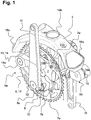
- the Fig. 1 shows a perspective view of the transmission according to the invention in the installed position, which can be connected by means of a frame element 2, for example with a bicycle frame, not shown here.
- the frame element 2 has three connection flanges 18a, 18b, 18c for connection to a front tube (connection flange 18a), a seat tube (connection flange 18b) and a rear structure (connection flange 18c).
- a first gear arrangement 6a is arranged on a first side 2a of the frame element 2 and a second gear arrangement 6b is arranged on the opposite, second side 2b.
- the second gear arrangement 6b located adjacent to the second side 2b lies in the image plane behind the frame element 2 and is largely covered by it.
- the first and second gear arrangement 6a, 6b act on a central shaft 1, which runs transversely through the frame element 2 and whose front end face is visible.
- the central shaft 1 defines the in Fig. 4 shown axis of rotation M of the gearbox (overall system).
- the second gear arrangement 6b is oriented, with respect to the direction of rotation of the central shaft 1, offset by 180 ° to the first gear arrangement 6a, so that a drive crank 11 of the first gear arrangement 6a points upwards and a drive crank 11 of the second gear arrangement 6b points downwards.
- a support plate 7 On both axial end sections of the central shaft 1, a support plate 7 is attached in a rotationally fixed manner, which carries out a circular rotary movement together with the central shaft 1 during operation of the transmission.
- the connection of the carrier plate 7 to the central shaft 1 takes place in a first section 7a arranged centrally in the carrier plate 7.
- a second section 7b is provided on the outside, which has a planet gear 8 (see Fig. 4 ) carries, which is rotatably supported by means of a planetary gear bearing 9 relative to the carrier plate 7.
- the planet gear bearing 9 engages a cylindrically shaped shaft 8 a of the planet gear 8.
- crank arm 10 is either attached in a rotationally fixed manner or integrally formed in one piece.
- the crank arm 10 protrudes in the radial direction with respect to the shaft 8a and acts on the drive crank 11 in a rotatable manner by means of a drive crank crank arm bearing 12.
- a kinematic coupling means 13 in the form of a pendulum arm 14 is also rotatably connected to the carrier plate 7.
- a pendulum arm carrier plate bearing 15 is provided between the carrier plate 7 and a first end 14a of the pendulum arm 14, which is particularly good in the illustration according to Fig. 4 you can see.
- the second end 14b opposite the first end 14a rotatably engages by means of a pendulum arm drive crank bearing 16 on the side of the drive crank 11 facing the frame element 2 (also compare Fig. 4 ).
- the carrier plate 7 of the first gear arrangement 6a is completely surrounded in the circumferential direction by a force transmission means 5, which is designed as a ring gear 17 in the exemplary embodiment of a bicycle transmission shown.
- the ring gear 17 is aligned concentrically with the central shaft 1.
- the force of the entire system is applied via the two drive cranks 11 of the first and second gear arrangement 6a, 6b, which limit the transmission in the axial direction of the central shaft 1 to the outside.
- the Figures 1 , 2nd and 4th show the drive cranks 11 and the associated gear assembly 6a, 6b in a 0 ° position, in which the drive crank 11 and the associated crank arm 10 are stretched, that is, the crank arm 10 starting from the shaft 8a of the planet gear 8 radially inward in the direction the central shaft 1 shows.
- the free end of the drive crank 11 is in a maximally extended position.
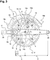
- Fig. 2 and 3rd are the 0 ° position ( Fig. 2 ) and the 90 ° position ( Fig. 3 ) of the drive cranks 11 in a side view of the transmission, the designations and relationships being explained essentially with the aid of the first transmission arrangement 6a for reasons of simplification.
- a pedal 19 At the free end of the drive cranks 11 is in Fig. 2 each attached to a pedal 19, for example, which is rotatably supported by means of a pedal bearing 20 relative to the associated drive crank 11.
- the pedal bearing 20 has a bearing axis P which is stationary with respect to the drive crank.
- the pendulum arm 14 is fastened to the carrier plate 7 at the first end 14a by means of the pendulum arm support plate bearing 15 and pivots revolving gear around a bearing axis B 0 .
- the pendulum arm 14 With the second end 14b, the pendulum arm 14 is rotatably connected to the drive crank 11 via the pendulum arm drive crank bearing 16.
- the pendulum arm drive crank bearing 16 has a bearing axis B, B ', the end position of the bearing axis B with that in Fig. 2 shown 0 ° position and the end position of the bearing axis B 'with in Fig. 3 shown 90 ° position corresponds.
- the respective other end position of the bearing axis B ', B is achieved by changing the position of the drive crank 11 and is indicated by a dotted line.
- the pendulum arm 14 sweeps on the bearing axis B 0 between the end positions of the bearing axis B, B 'a swivel angle ⁇ , which can preferably be between 25 ° and 50 °.
- the bearing axis P and the bearing axis B, B ' are spaced apart from one another by a distance a.
- the distance a is always constant regardless of the position of the first or second gear arrangement 6a, 6b.
- the distance a is preferably 100 mm to 200 mm, particularly preferably 130 mm to 160 mm and very particularly preferably 145 mm to 155 mm.
- the crank arm 10 is rotatably attached to the drive crank 11 and simultaneously to the planet gear bearing 9 by means of the drive crank crank arm bearing 12, wherein the drive crank crank arm bearing 12 has a bearing axis A which is stationary with respect to the drive crank 11 and the planet gear bearing 9 has a stationary bearing axis A 0 with respect to the carrier plate 7.
- the shaft 8a of the planet gear 8 rotates about the bearing axis A 0 .
- the bearing axis B, B 'and the bearing axis A are spaced apart from one another by a distance b.
- the distance b is always constant regardless of the position of the first and second gear arrangement 6a, 6b.
- the bearing axis B ' is located exactly in the axis of rotation M in order to achieve a maximum torque in the 90 ° position (see Fig. 4 ) of the overall system.
- An offset of the bearing axis B 'in the direction of the bearing axis A results in the 90 ° position accordingly Fig. 3 a negative torque, which counteracts the actual direction of rotation of the transmission, for example in the area of the central shaft 1, and should be avoided if possible.
- An offset of the bearing axis B 'in the direction of the bearing axis P causes additional propulsive torque, but increases the structural dimensions of the transmission.
- the offset of the bearing axis B 'to the axis of rotation M should be less than 10% of the distance b in both directions.
- a perpendicular perpendicular s on which the bearing axis B 0 of the pendulum arm support plate bearing 15 is arranged.
- the perpendicular bisector s generally has a value greater than 0, that is to say there is always an offset of the bearing axis B 0 to the drive crank 11. Under this condition there is always a distance d between the bearing axis B and the bearing axis B 0 .
- the two bearing axes A, A 0 are aligned at a distance c from one another which is the same in the 0 ° position and in the 90 ° position.
- the bearing axes A, A have 0 starting from the 0 ° position accordingly Fig. 2 compared to the 90 ° position accordingly Fig. 3 swapped their position.
- the addition of the distances a, b, c is reduced by the distance c and the drive crank 11 takes with respect to the axis of rotation M (see Fig. 4 ) a retracted position.
- the bearing axis A 0 is aligned with the bearing axis B 0 at a distance g, which due to the fixed arrangement of the planetary gear bearing 9 and the pendulum arm support plate bearing 15 on the support plate 7 regardless of the position of the first and second gear arrangement 6a, 6b is constant.
- the distance g should be larger than the distance b, c or d.
- the longitudinal section of the Fig. 4 also shows the first and second sun gear 4a, 4b which are fixed with respect to the frame element 2, the first sun gear 4a being arranged on the first side 2a of the frame element 2 and the second sun gear 4b being arranged on the opposite, second side 2b.
- the sun gear 4a is fixedly connected to the sun gear 4b via a hollow cylinder 4c, the sun gears 4a, 4b and the hollow cylinder 4c being designed as a one-piece, integral unit.
- a one-piece, integral structural unit is understood to mean a connection that cannot be separated without being destroyed.
- the first and second sun gear 4a, 4b are clampingly connected to the frame element 2 via the hollow cylinder 4c.
- the frame element 2 has an upper shell 2c which is at least partially complementary to the outer contour of the hollow cylinder 4c and which bears against the hollow cylinder 4c in the image plane from above.
- a lower shell 2d abuts the hollow cylinder 4c from the other side and is firmly clamped to the upper shell 2c.
- the axial extent of the hollow cylinder 4c corresponds to the width of the upper and / or lower shell 2c, 2d, so that the first and second sun gear 4a, 4b are positioned exactly between them and held laterally during operation.
- the central shaft 1 which is rotatably mounted in the area of the first and second sun gear 4a, 4b by means of a central shaft bearing 3, runs concentrically within the hollow cylinder 4c. Because of the axial shaft of the central shaft 1 as far out as possible, coaxially Tilting moments acting on the central shaft 1 can be absorbed particularly well within the first and second sun gear 4a, 4b.
Landscapes
- Engineering & Computer Science (AREA)
- Mechanical Engineering (AREA)
- Chemical & Material Sciences (AREA)
- Combustion & Propulsion (AREA)
- Transportation (AREA)
- General Engineering & Computer Science (AREA)
- Transmission Devices (AREA)
- Structure Of Transmissions (AREA)
- Retarders (AREA)
Description
Die Erfindung betrifft ein Getriebe gemäß der im Oberbegriff des Anspruchs 1 stehenden Merkmale.The invention relates to a transmission according to the features in the preamble of
Derartige Getriebe können insbesondere in Fahrrädern verbaut sein und sorgen für eine Vergrößerung des Drehmomentes durch die vom Radfahrer eingeleitete Kraft. Bei dieser Anwendung wird das Gehäuse des Getriebes an ein Rahmenbauteil adaptiert und das Kraftübertragungsmittel, zum Beispiel ein Zahnkranz, überträgt das vom Radfahrer erzeugte Drehmoment über eine Kette auf das Hinterrad. Das erfindungsgemäße Getriebe kann jedoch ebenso beispielsweise an Windkraftanlagen mit senkrecht stehenden Rotationsachsen vorgesehen sein.Such gears can be installed in particular in bicycles and ensure an increase in torque by the force introduced by the cyclist. In this application, the housing of the transmission is adapted to a frame component and the force transmission means, for example a ring gear, transmits the torque generated by the cyclist to the rear wheel via a chain. However, the transmission according to the invention can also be provided, for example, on wind turbines with vertical axes of rotation.
Die
Einen Stand der Technik bildet die
Weitere relevante Dokumente der Stand der Technik sind
Folglich lag der Erfindung die Aufgabe zugrunde, ein Getriebe bereitzustellen, dass in axialer Richtung der Zentralwelle möglichst kompakte Abmessungen aufweist und dessen rotierende Antriebskurbel möglichst spielfrei geführt ist.Consequently, the object of the invention was to provide a transmission which has dimensions which are as compact as possible in the axial direction of the central shaft and whose rotating drive crank is guided with as little play as possible.
Die Aufgabe wird erfindungsgemäß mit dem kennzeichnenden Merkmal des Anspruchs 1 gelöst. Unter einem Pendelarm wird ein starres Bauteil verstanden, welches ausgehend von einer Mittellage mit einem Ende in zwei Richtungen um einen Lagerpunkt schwenkt. Hieraus resultiert der Vorteil, dass auf kinematisch zwar optimale aber im Betrieb anfällige Dreh-Schub-Gelenke verzichtet werden kann und alle eingesetzten Lager als Drehlager ausgeführt sein können.The object is achieved with the characterizing feature of
Das erfindungsgemäße Getriebe ermöglicht die Bildung eines maximalen Momentes durch Zuhilfenahme einer Kraftübersetzung bei gleichzeitiger Führung eines krafteinleitenden Elementes längs einer homogenen Bahn. Das krafteinleitende Element kann beispielsweise der Fuß eines Radfahrers sein. Die Homogenität resultiert sowohl aus der durchgehend konvexen Bahnform als auch der Reduzierung von absoluten Beschleunigungen im Bereich des krafteinleitenden Elementes. Das Verhältnis zwischen Maximum und Minimum der Absolutgeschwindigkeiten überschreitet in keinem Bahnpunkt den Wert 2,5.The transmission according to the invention enables the formation of a maximum torque by using a force transmission while simultaneously guiding a force-introducing element along a homogeneous path. The force-introducing element can, for example, be the foot of one Be a cyclist. The homogeneity results both from the continuously convex path shape and the reduction of absolute accelerations in the area of the force-introducing element. The ratio between maximum and minimum of the absolute speeds does not exceed 2.5 at any path point.
Das erste und/oder ein gegebenenfalls. vorhandenes zweites Sonnenrad führt vorzugsweise mit dem damit zusammenwirkenden Planetenrad zu einem Übersetzungsverhältnis von 1:2. Ein grundsätzlich auch in der Praxis sinnvolles Übersetzungsverhältnis kann alternativ 1:4 betragen.The first and / or one if necessary. Existing second sun gear preferably leads to a gear ratio of 1: 2 with the planet gear interacting with it. A gear ratio that is generally also useful in practice can alternatively be 1: 4.
In dem erfindungsgemäßen Getriebe als Gesamtsystem dient die Antriebskurbel, vorzugsweise in einer Lagerachse eines Pedal-Lagers P, als Antrieb und die Trägerplatte als Abtrieb.In the transmission according to the invention as an overall system, the drive crank, preferably in a bearing axis of a pedal bearing P, serves as the drive and the carrier plate as the output.
Vorteilhafterweise ist der Pendelarm mit seinem ersten Ende mittels eines Pendelarm-Trägerplatte-Lagers drehbeweglich an der Trägerplatte und an seinem zweiten Ende mittels eines Pendelarm-Antriebskurbel-Lagers drehbeweglich an der Antriebskurbel gelagert. Dabei bilden das Planetenrad-Lager, das Antriebskurbel-Kurbelarm-Lager, das Pendelarm-Antriebskurbel-Lager und das Pendelarm-Trägerplatte-Lager innerhalb des Gesamtsystems des Getriebes ein Viergelenk, wobei das Viergelenk bei dieser Betrachtung von dem kontinuierlich umlaufenden Kurbelarm angetrieben ist. Der Kurbelarm weist stets die kleinste Länge innerhalb des Viergelenks auf. Der Abtrieb des Viergelenks erfolgt mittels des Pendelarms, der eine schwingende Bewegung um das Pendelarm-Trägerplatte-Lager ausführt. Der Kurbelarm und der Pendelarm sind über eine Koppel miteinander verbunden, welche aus einem Abschnitt der Antriebskurbel zwischen dessen Antriebskurbel-Kurbelarm-Lager und dem Pendelarm-Antriebskurbel-Lager gebildet ist. Sowohl der Kurbelarm als auch der Pendelarm sind drehbar an der Trägerplatte gelagert, wobei der Kurbelarm fest mit einer Welle des umlaufenden Planetenrades verbunden ist. Das Pendelarm-Antriebskurbel-Lager vollzieht anstelle einer linearen Bewegung eines Dreh-Schub-Gelenkes lediglich eine angenähert lineare Bewegung auf einer Kreisbahn mit sehr großem Radius.Advantageously, the pendulum arm is rotatably supported at its first end by means of a pendulum arm support plate bearing on the support plate and at its second end by means of a pendulum arm drive crank bearing on the drive crank. The planetary gear bearing, the drive crank crank arm bearing, the pendulum arm drive crank bearing and the pendulum arm support plate bearing form a four-bar linkage within the overall system of the transmission, the four-bar linkage being driven by the continuously rotating crank arm in this view. The crank arm always has the smallest length within the four-bar linkage. The four-bar linkage is driven by the pendulum arm, which carries out a swinging movement around the pendulum arm support plate bearing. The crank arm and the pendulum arm are connected to one another via a coupling which is formed from a section of the drive crank between its drive crank crank arm bearing and the pendulum arm drive crank bearing. Both the crank arm and the pendulum arm are rotatably mounted on the support plate, the Crank arm is firmly connected to a shaft of the rotating planet gear. Instead of a linear movement of a rotary-thrust joint, the pendulum arm drive crank bearing only performs an approximately linear movement on a circular path with a very large radius.
Es hat sich als besonders günstig erwiesen, wenn der Kurbelarm und der Pendelarm auf einer gemeinsamen Seite der Antriebskurbel angeordnet sind. Die Antriebskurbel liegt somit bezüglich des Getriebes in axialer Richtung der Zentralwelle außen, was zu einem besonders geringen Q-Faktor beiträgt. Vorteilhafterweise sind dann auch der Kurbelarm und der Pendelarm in axialer Richtung der Zentralwelle zwischen der Trägerplatte und der Antriebskurbel angeordnet.It has proven to be particularly favorable if the crank arm and the pendulum arm are arranged on a common side of the drive crank. The drive crank is thus outside with respect to the transmission in the axial direction of the central shaft, which contributes to a particularly low Q factor. The crank arm and the pendulum arm are then advantageously also arranged in the axial direction of the central shaft between the carrier plate and the drive crank.
Vorzugsweise ist bei einer vollständigen Umdrehung der Trägerplatte von dem Pendelarm um das Pendelarm-Trägerplatte-Lager ein maximaler Schwenkwinkel von 25° bis 50° überstrichen. Bei diesem maximalen Schwenkwinkeln arbeitet das Getriebe besonders effektiv.With a complete rotation of the support plate from the pendulum arm around the pendulum arm support plate bearing, a maximum swivel angle of 25 ° to 50 ° is preferably swept. At this maximum swivel angle, the transmission works particularly effectively.
Zweckmäßigerweise nimmt das Pendelarm-Trägerplatte-Lager eine Position auf einer Mittelsenkrechten ein, welche senkrecht auf einer zwischen der Lagerachse des Pendelarm-Antriebskurbel-Lagers in dessen 0° und 90° Stellung verlaufenden Verbindungslinie steht. Die beiden Lagerachsen liegen somit in ihren Endlagen auf einer Geraden, welche die Drehachse des Getriebes schneidet. Das Viergelenk stellt dann eine zentrische Kurbelschwinge dar.The pendulum arm support plate bearing expediently assumes a position on a perpendicular, which is perpendicular to a connecting line running between the bearing axis of the pendulum arm drive crank bearing in its 0 ° and 90 ° position. The two bearing axes are thus in their end positions on a straight line that intersects the axis of rotation of the gearbox. The four-bar linkage then represents a central crank arm.
Gemäß einer besonders vorteilhaften Ausführungsform ist/sind das Pendelarm-Trägerplatte-Lager und/oder das Antriebskurbel-Kurbelarm-Lager innerhalb eines Außenumfangs des Kraftübertragungsmittels angeordnet. Hierdurch wird in radialer Richtung des Kraftübertragungsmittels eine besonders kompakte Bauweise erzielt, bei welcher unabhängig von der Stellung der Antriebskurbel -abgesehen von dieser- kein Bauteil über das Kraftübertragungsmittel hinausragt, so dass beispielsweise konventionelle Kettenkästen oder andere Einhausungen für das Kraftübertragungsmittel vorgesehen werden können, ohne dass das Kraftübertragungsmittel mit diesen kollidiert.According to a particularly advantageous embodiment, the pendulum arm support plate bearing and / or the drive crank crank arm bearing is / are arranged within an outer circumference of the force transmission means. As a result, a particularly compact design is achieved in the radial direction of the force transmission means which - regardless of the position of the drive crank - apart from this - no component projects beyond the force transmission means, so that, for example, conventional chain boxes or other housings can be provided for the force transmission means without the force transmission means colliding with them.
Der Abstand zwischen dem Pendelarm-Trägerplatte-Lager und dem Pendelarm-Antriebskurbel-Lager kann größer als der Abstand zwischen dem Pendelarm-Antriebskurbel-Lager und dem Antriebskurbel-Kurbelarm-Lager ausgeführt sein. Für ein umlauffähiges Getriebe sollten darüber hinaus die nachfolgenden Voraussetzungen vorliegen:
- g > d > c
- d > b > c
- s ≠ 0
- mit g:
- Abstand zwischen Lagerachse Planetenrad-Lager (A0) und Lagerachse Pendelarm-Trägerplatte-Lager (B0).
- mit d:
- Abstand zwischen Lagerachse Pendelarm-Trägerplatte-Lager (B0) und Lagerachse Pendelarm-Antriebskurbel-Lager (B, B').
- mit c:
- Abstand zwischen Lagerachse Planetenrad-Lager (A0) und Lagerachse Antriebskurbel-Kurbelarm-Lager (A).
- mit b:
- Abstand zwischen Lagerachse Antriebskurbel-Kurbelarm-Lager (A) und Lagerachse Pendelarm-Antriebskurbel-Lager (B, B').
- mit s:
- Länge der durch die Lagerachse Pendelarm-Trägerplatte-Lager (B0) verlaufenden Mittelsenkrechten, welche senkrecht auf einer zwischen der Lagerachse (B, B') des Pendelarm-Antriebskurbel-Lagers in dessen 0° und 90° Stellung verlaufenden Verbindungslinie steht.
- g>d> c
- d>b> c
- s ≠ 0
- with g:
- Distance between the bearing axis of the planetary gear bearing (A 0 ) and the bearing axis of the pendulum arm support plate bearing (B 0 ).
- with d:
- Distance between the bearing axis of the pendulum arm support plate bearing (B 0 ) and the bearing axis of the pendulum arm drive crank bearing (B, B ').
- with c:
- Distance between the bearing axis of the planetary gear bearing (A 0 ) and the bearing axis of the drive crank / crank arm bearing (A).
- with b:
- Distance between the bearing axis of the drive crank crank arm bearing (A) and the bearing axis of the pendulum arm drive crank bearing (B, B ').
- with s:
- Length of the perpendicular bisectors running through the bearing axis of the pendulum arm support plate bearing (B 0 ), which are vertical stands on a connecting line running between the bearing axis (B, B ') of the pendulum arm drive crank bearing in its 0 ° and 90 ° position.
Unter dem Begriff "Lagerachse" wird die Position der Drehachse des jeweiligen Lagers unabhängig von dessen Dimensionierung oder sonstigen konstruktiven Beschaffenheit verstanden.The term "bearing axis" is understood to mean the position of the axis of rotation of the respective bearing regardless of its dimensioning or other constructional nature.
Vorzugsweise spannen das Pendelarm-Trägerplatte-Lager, das Pendelarm-Antriebskurbel-Lager und das Antriebskurbel-Kurbelarm-Lager stets ein Dreieck auf.The pendulum arm support plate bearing, the pendulum arm drive crank bearing and the drive crank crank arm bearing preferably always span a triangle.
Günstigerweise ist/sind das Planetenrad-Lager und/oder das Antriebskurbel-Kurbelarm-Lager und/oder das Pendelarm-Trägerplatte-Lager und/oder das Pendelarm-Antriebskurbel-Lager jeweils separat gegen Schmutz und Spritzwasser abgedichtet. Die Abdichtung der vorstehend genannten, außenliegenden Lager kann mittels berührender Lippendichtungen erfolgen. Das oder die Zentralwellenlager ist/sind vorzugsweise durch eine Abdeckplatte (Spaltdichtung) abgedichtet. Hierdurch lässt sich eine effektive Dichtwirkung erzielen. Darüber hinaus kann auf großräumige Umhüllungen beispielsweise mittels Faltenbalge verzichtet werden. Diese sind einerseits anfällig gegen Beschädigungen und stören andererseits die optische Anmutung des Getriebes.The planet gear bearing and / or the drive crank crank arm bearing and / or the pendulum arm support plate bearing and / or the pendulum arm drive crank bearing are / are each separately sealed against dirt and splash water. The external bearings mentioned above can be sealed by means of touching lip seals. The central shaft bearing or bearings is / are preferably sealed by a cover plate (gap seal). This allows an effective sealing effect to be achieved. In addition, large-scale envelopes, for example by means of bellows, can be dispensed with. On the one hand, these are susceptible to damage and, on the other hand, disturb the visual appearance of the transmission.
Vorteilhafterweise ist das erste Sonnenrad an einer ersten Seite des Rahmenelementes angeordnet. Diese Einbaulage korrespondiert beispielsweise mit den konventionell eingebauten Tretlagern eines Fahrrades.The first sun gear is advantageously arranged on a first side of the frame element. This installation position corresponds, for example, to the conventionally installed bottom bracket of a bicycle.
Ganz besonders bevorzugt ist es, insbesondere bei einer Anwendung des erfindungsgemäßen Getriebes an einem Fahrrad, wenn an einer bezüglich des Rahmenelementes der ersten Seite gegenüberliegenden, zweiten Seite ein zweites Sonnenrad vorgesehen ist, welches mit einer gegenüber dem Rahmenelement rotierenden zweiten Getriebeanordnung zusammenwirkt, wobei die zweite Getriebeanordnung um 180° zu der ersten Getriebeanordnung versetzt ist und eine Trägerplatte umfasst,
- deren erster Abschnitt drehfest mit der Zentralwelle verbunden und an deren zweitem Abschnitt ein Planetenrad mittels eines Planetenrad-Lagers gelagert ist, das Planetenrad das zweite Sonnenrad kämmt und an dem Planetenrad starr ein Kurbelarm angreift, sowie
- eine Antriebskurbel, an welcher der Kurbelarm mittels eines Antriebskurbel-Kurbelarm-Lagers drehgelenkig gelagert und welche über einen Pendelarm gegenüber der Trägerplatte abgestützt ist.
- the first section of which is connected in a rotationally fixed manner to the central shaft and on the second section of which a planet gear is mounted by means of a planet gear bearing, the planet gear meshes with the second sun gear and a crank arm rigidly engages the planet gear, and
- a drive crank, on which the crank arm is pivotally mounted by means of a drive crank crank arm bearing and which is supported against the carrier plate via a pendulum arm.
Hierdurch wird ein Getriebe bereitgestellt, welches ausgehend von einer mittig angeordneten Zentralwelle auf jeder Seite ein Sonnenrad und eine das Sonnenrad umkreisende, symmetrische Getriebeanordnung aufweist. Das ortsfest zur Zentralwelle angeordnete Kraftübertragungsmittel braucht lediglich auf einer Seite des Rahmenelementes angeordnet zu sein.This provides a transmission which, starting from a centrally arranged central shaft, has a sun gear on each side and a symmetrical gear arrangement encircling the sun gear. The power transmission means fixed to the central shaft need only be arranged on one side of the frame element.
Vorzugsweise ist/sind die Zentralwelle und/oder das mindestens eine Zentralwellenlager konzentrisch innerhalb des ersten und/oder zweiten Sonnenrades angeordnet. Der Vorteil dieser Ausführungsform liegt darin, dass das Getriebe in axialer Richtung der Zentralwelle besonders kompakte Abmessungen aufweist.The central shaft and / or the at least one central shaft bearing is / are preferably arranged concentrically within the first and / or second sun gear. The advantage of this embodiment is that the transmission has particularly compact dimensions in the axial direction of the central shaft.
Das erste und zweite Sonnenrad können monolithisch hergestellt sein. Gemäß einer bevorzugten Ausführungsform sind das erste und zweite Sonnenrad jeweils als Zahnrad ausgebildet. In diesem Fall bedeutet eine monolithische Herstellung, dass die Zahnräder von dem ersten und dem zweiten Sonnenrad mittels eines Hohlzylinders fest miteinander verbunden sind und üblicherweise die Verzahnung beider miteinander verbundener Zahnräder in einem gemeinsamen formgebenden Arbeitsschritt entsteht. Hierdurch fluchten die Zähne des ersten Sonnenrades möglichst exakt mit den Zähnen des zweiten Sonnenrades. Das die miteinander verbundenen Zahnräder aufnehmende Rahmenelement weist in seinem unteren Abschnitt eine Oberschale und eine Unterschale auf, die in zusammengefügtem Zustand mit einer zu dem Hohlzylinder komplementären Form ausgebildet ist. Zur Montage wird der Hohlzylinder zunächst in die Oberschale eingelegt und anschließend die Unterschale mit der Oberschale verbunden, insbesondere verschraubt. Grundsätzlich ist der Hohlzylinder klemmend von der Oberschale und der Unterschale gehalten.The first and second sun gear can be made monolithic. According to a preferred embodiment, the first and second sun gear are each designed as a gear. In this case, a monolithic production means that the gear wheels of the first and the second sun gear are firmly connected to one another by means of a hollow cylinder and usually the interlocking of the two with one another connected gears in a common shaping step. As a result, the teeth of the first sun gear are aligned as precisely as possible with the teeth of the second sun gear. In its lower section, the frame element receiving the interconnected gears has an upper shell and a lower shell, which in the assembled state is designed with a shape complementary to the hollow cylinder. For assembly, the hollow cylinder is first inserted into the upper shell and then the lower shell is connected, in particular screwed, to the upper shell. Basically, the hollow cylinder is held in a clamped manner by the upper shell and the lower shell.
Vorteilhafterweise ist das Kraftübertragungsmittel ein Zahnkranz, der vorzugsweise mit einer Kette oder einem Zahnriemen zusammenwirkt beziehungsweise in diese(n) eingreift. Alternativ hierzu ist es auch möglich, ein Kraftübertragungsmittel in Form eines Antriebsrades vorzusehen, welches ohne Formschlusselemente beispielsweise einen Riemen antreibt.The force transmission means is advantageously a toothed ring, which preferably interacts with a chain or a toothed belt or engages in it. As an alternative to this, it is also possible to provide a force transmission means in the form of a drive wheel which, for example, drives a belt without positive locking elements.
Zweckmäßigerweise ist der Zahnkranz an der Trägerplatte der ersten und/oder zweiten Getriebeanordnung befestigt. Hierdurch ergibt sich eine in axialer Richtung der Zentralwelle kompakte Bauweise des Getriebes, da für die Trägerplatte ohnehin ein entsprechender Bauraum vorzuhalten ist und der Zahnkranz ebenfalls beabstandet zu der nächstliegenden ersten Seite des Rahmenelement angeordnet ist, um einen freien Lauf der Kette zu ermöglichen.The gear rim is expediently attached to the carrier plate of the first and / or second gear arrangement. This results in a compact construction of the transmission in the axial direction of the central shaft, since a corresponding installation space has to be provided anyway for the carrier plate and the toothed ring is also arranged at a distance from the nearest first side of the frame element in order to allow the chain to run freely.
Zum besseren Verständnis wird die Erfindung nachfolgend anhand von vier Figuren erläutert. Es zeigen die
- Fig. 1:
- eine perspektivische Ansicht auf das Getriebe mit Antriebskurbeln in der 0°-Stellung;
- Fig. 2:
- eine Seitenansicht auf das Getriebe mit Antriebskurbeln in der 0°-Stellung;
- Fig. 3:
- eine Seitenansicht auf das Getriebe mit Antriebskurbeln in der 90°-Stellung und
- Fig. 4:
- einen Längsschnitt durch das Getriebe entsprechend der Schnittebene A:A in
Fig. 2 .
- Fig. 1:
- a perspective view of the transmission with drive cranks in the 0 ° position;
- Fig. 2:
- a side view of the transmission with drive cranks in the 0 ° position;
- Fig. 3:
- a side view of the transmission with drive cranks in the 90 ° position and
- Fig. 4:
- a longitudinal section through the gearbox according to the section plane A: A in
Fig. 2 .
Die
Auf einer ersten Seite 2a des Rahmenelementes 2 ist eine erste Getriebeanordnung 6a und auf der gegenüberliegenden, zweiten Seite 2b eine zweite Getriebeanordnung 6b angeordnet. Die benachbart zur zweiten Seite 2b befindliche, zweite Getriebeanordnung 6b liegt in der Bildebene hinter dem Rahmenelement 2 und ist in großen Teilen durch dieses verdeckt.A
Die erste und zweite Getriebeanordnung 6a, 6b wirken auf eine Zentralwelle 1, die quer durch das Rahmenelement 2 verläuft und dessen vordere Stirnseite sichtbar ist. Die Zentralwelle 1 definiert die in
Die zweite Getriebeanordnung 6b ist, bezogen auf den Drehsinn der Zentralwelle 1, um 180° versetzt zu der ersten Getriebeanordnung 6a ausgerichtet, so dass eine Antriebskurbel 11 der ersten Getriebeanordnung 6a nach oben und eine Antriebskurbel 11 der zweiten Getriebeanordnung 6b nach unten weist.The
An beiden axialen Endabschnitten der Zentralwelle 1 ist drehfest eine Trägerplatte 7 angebracht, welche im Betrieb des Getriebes zusammen mit der Zentralwelle 1 eine kreisförmige Drehbewegung ausführt. Die Verbindung der Trägerplatte 7 mit der Zentralwelle 1 erfolgt in einem zentrisch in der Trägerplatte 7 angeordneten ersten Abschnitt 7a. In radialer Richtung der Trägerplatte 7 ist außenliegend ein zweiter Abschnitt 7b vorgesehen, welcher ein Planetenrad 8 (siehe
An dem bezüglich des Rahmenelementes 2 äußeren Ende der Welle 8a ist ein Kurbelarm 10 entweder drehfest angebracht oder integral, einstückig ausgeformt. Der Kurbelarm 10 steht in radialer Richtung gegenüber der Welle 8a vor und greift mittels eines Antriebskurbel-Kurbelarm-Lagers 12 drehbeweglich an der Antriebskurbel 11 an.At the outer end of the
Mit der Trägerplatte 7 ist außerdem ein kinematisches Kopplungsmittel 13 in Form eines Pendelarms 14 drehbeweglich verbunden. Hierfür ist zwischen der Trägerplatte 7 und einem ersten Ende 14a des Pendelarmes 14 ein Pendelarm-Trägerplatte-Lager 15 vorgesehen, welches besonders gut in der Darstellung gemäß
Die Trägerplatte 7 der ersten Getriebeanordnung 6a ist in Umfangsrichtung vollständig von einem Kraftübertragungsmittel 5 umgeben, das bei dem gezeigten Ausführungsbeispiel eines Fahrradgetriebes als Zahnkranz 17 ausgebildet ist. Der Zahnkranz 17 ist dabei konzentrisch zu der Zentralwelle 1 ausgerichtet.The
Die Krafteinleitung des Gesamtsystems erfolgt über die zwei Antriebskurbeln 11 jeweils der ersten und zweiten Getriebeanordnung 6a, 6b, welche das Getriebe in axialer Richtung der Zentralwelle 1 nach außen begrenzen. Die
Anhand der
An dem freien Ende der Antriebskurbeln 11 ist in
Der Pendelarm 14 ist an dem ersten Ende 14a mittels des Pendelarm-Trägerplatte-Lagers 15 an der Trägerplatte 7 befestigt und schwenkt bei umlaufendem Getriebe um eine Lagerachse B0. Mit dem zweiten Ende 14b ist der Pendelarm 14 über das Pendelarm-Antriebskurbel-Lager 16 drehbar mit der Antriebskurbel 11 verbunden. Das Pendelarm-Antriebskurbel-Lager 16 weist eine Lagerachse B, B' auf, wobei die Endlage der Lagerachse B mit der in
Die Lagerachse P und die Lagerachse B, B' sind in einem Abstand a zueinander beabstandet. Der Abstand a ist unabhängig von der Lage der ersten oder zweiten Getriebeanordnung 6a, 6b stets konstant. Bei einem an einem Fahrrad verbauten Getriebe beträgt der Abstand a bevorzugt 100 mm bis 200 mm, besonders bevorzugt 130 mm bis 160 mm und ganz besonders bevorzugt 145 mm bis 155 mm.The bearing axis P and the bearing axis B, B 'are spaced apart from one another by a distance a. The distance a is always constant regardless of the position of the first or
Der Kurbelarm 10 ist mittels des Antriebskurbel-Kurbelarm-Lagers 12 an der Antriebskurbel 11 und gleichzeitig an dem Planetenrad-Lager 9 jeweils drehbar angebracht, wobei das Antriebskurbel-Kurbelarm-Lager 12 eine bezüglich der Antriebskurbel 11 ortsfeste Lagerachse A und das Planetenrad-Lager 9 eine bezüglich der Trägerplatte 7 ortsfeste Lagerachse A0 aufweist. Um die Lagerachse A0 dreht die Welle 8a des Planetenrades 8.The
Die Lagerachse B, B' und die Lagerachse A sind in einem Abstand b zueinander beabstandet. Der Abstand b ist unabhängig von der Lage der ersten und zweiten Getriebeanordnung 6a, 6b stets konstant.The bearing axis B, B 'and the bearing axis A are spaced apart from one another by a distance b. The distance b is always constant regardless of the position of the first and
In der bevorzugten und gezeigten Ausführungsform des Getriebes befindet sich zur Erreichung eines maximalen Drehmomentes in der 90°-Stellung die Lagerachse B' genau in der Drehachse M (siehe
Exakt zwischen der Lagerachse B (
Die beiden Lagerachsen A, A0 sind in einem Abstand c zueinander ausgerichtet, welcher dem Betrag nach in der 0°-Stellung und in der 90°-Stellung gleich ist. Allerdings haben die Lagerachsen A, A0 ausgehend von der 0°-Stellung entsprechend
Die Lagerachse A0 ist zu der Lagerachse B0 in einem Abstand g ausgerichtet, der aufgrund der ortsfesten Anordnung des Planetenrad-Lagers 9 und des Pendelarm-Trägerplatte-Lagers 15 jeweils an der Trägerplatte 7 unabhängig von der Lage der ersten und zweiten Getriebeanordnung 6a, 6b konstant ist. Der Abstand g sollte dem Betrag nach größer als der Abstand b, c oder d sein.The bearing axis A 0 is aligned with the bearing axis B 0 at a distance g, which due to the fixed arrangement of the
Der Längsschnitt der
Innerhalb des Hohlzylinders 4c verläuft konzentrisch die Zentralwelle 1, welche im Bereich des ersten und zweiten Sonnenrades 4a, 4b mittels jeweils eines Zentralwellenlagers 3 drehbar gelagert ist. Aufgrund der in axialer Richtung der Zentralwelle 1 möglichst weit außen, koaxial innerhalb des ersten und zweiten Sonnenrades 4a, 4b angeordneten Zentralwellenlager 3 können besonders gut auf die Zentralwelle 1 wirkende Kippmomente aufgenommen werden.The
- 11
- ZentralwelleCentral shaft
- 22nd
- RahmenelementFrame element
- 2a2a
- erste Seite Rahmenelementfirst page frame element
- 2b2 B
- zweite Seite Rahmenelementsecond side frame element
- 2c2c
- Oberschale RahmenelementUpper shell frame element
- 2d2d
- Unterschale RahmenelementLower shell frame element
- 33rd
- ZentralwellenlagerCentral shaft bearing
- 4a4a
- erstes Sonnenradfirst sun gear
- 4b4b
- zweites Sonnenradsecond sun gear
- 4c4c
- HohlzylinderHollow cylinder
- 55
- KraftübertragungsmittelPower transmission means
- 6a6a
- erste Getriebeanordnungfirst gear arrangement
- 6b6b
- zweite Getriebeanordnungsecond gear arrangement
- 77
- TrägerplatteCarrier plate
- 7a7a
- erster Abschnitt Trägerplattefirst section carrier plate
- 7b7b
- zweiter Abschnitt Trägerplattesecond section of carrier plate
- 88th
- PlanetenradPlanet gear
- 8a8a
- Welle PlanetenradShaft planet gear
- 99
- Planetenrad-LagerPlanet gear bearings
- 1010th
- KurbelarmCrank arm
- 1111
- AntriebskurbelDrive crank
- 1212th
- Antriebskurbel-Kurbelarm-LagerCrank crank arm bearing
- 1313
- kinematisches Kopplungsmittelkinematic coupling agent
- 1414
- PendelarmPendulum arm
- 14a14a
- erstes Ende Pendelarmfirst end pendulum arm
- 14b14b
- zweites Ende Pendelarmsecond end pendulum arm
- 1515
- Pendelarm-Trägerplatte-LagerPendulum arm support plate bearing
- 1616
- Pendelarm-Antriebskurbel-LagerPendulum arm drive crank bearing
- 1717th
- ZahnkranzSprocket
- 18a18a
- Anschlussflansch VorderrohrFront pipe connection flange
- 18b18b
- Anschlussflansch SattelrohrSaddle tube connection flange
- 18c18c
- Anschlussflansch HinterbauRear flange connection flange
- 1919th
- Pedalpedal
- 2020th
- Pedal-LagerPedal bearings
- αα
- Schwenkwinkel PendelarmSwivel angle pendulum arm
- A0 A 0
- Lagerachse Planetenrad-LagerBearing axis planet gear bearing
- AA
- Lagerachse Antriebskurbel-Kurbelarm-LagerBearing axis drive crank crank arm bearing
- B0 B 0
- Lagerachse Pendelarm-Trägerplatte-LagerBearing axis pendulum arm support plate bearing
- BB
- Lagerachse Pendelarm-Antriebskurbel-Lager, 0° StellungBearing axis pendulum arm drive crank bearing, 0 ° position
- B'B '
- Lagerachse Pendelarm-Antriebskurbel-Lager, 90° StellungBearing axis pendulum arm drive crank bearing, 90 ° position
- MM
- Drehachse GesamtsystemOverall system axis of rotation
- PP
- Lagerachse Pedal-LagerBearing axle pedal bearing
- aa
-
Abstand
BP ,B'P distanceBP ,B'P - bb
-
Abstand
AB ,AB' distanceFROM ,FROM' - cc
-
Abstand
A0A distanceA 0 A - dd
-
Abstand
B0B ,B0B' distanceB 0 B ,B 0 B ' - gG
-
Abstand
A0B0 distanceA 0 B 0 - ss
- MittelsenkrechtePerpendicular bisector
Claims (11)
- A gearbox, having- a central shaft (1), which is rotatably mounted relative to a stationary frame element (2) by means of at least one central shaft bearing (3);- a first sun gear (4a) arranged concentrically around the central shaft (1) and fixedly connected to the frame element (2) ;- a power transmission means (5) arranged in a stationary manner relative to the central shaft (1); and- at least one first gearbox assembly (6a) rotating relative to the frame element (2), and comprising- a support plate (7), the first portion (7a) of which is non-rotatably connected to the central shaft (1) and on the second portion (7b) of which a planetary gear (8) is mounted by means of a planetary gear bearing (9), wherein the planetary gear (8) meshes with the first sun gear (4a) and a crank arm (10) rigidly engages with the planetary gear (8); and- a driving crank (11), on which the crank arm (10) is pivotally mounted by means of a driving crank/crank arm bearing (12) and which is supported relative to the support plate (7) by means of a kinematic coupling means (13),wherein the kinematic coupling means (13) is a swing arm (14), characterized in that the swing arm (14) is rotatably mounted on the support plate (7) with its first end (14a) by means of a swing arm/support plate bearing (15) and is rotatably mounted on the driving crank (11) with its second end (14b) by means of a swing arm/driving crank bearing (16).
- The gearbox according to claim 1, characterized in that the crank arm (10) and the swing arm (14) are arranged on a common side of the driving crank (11).
- The gearbox according to claim 1 or 2, characterized in that, during a complete rotation of the support plate (7) of the swing arm (14) about the swing arm/support plate bearing (15), a maximum pivot angle (α) of 25° to 50° is covered.
- The gearbox according to any one of claim 1 to 3, characterized in that the swing arm/support plate bearing (15) assumes a position (B0) on a perpendicular bisector (s) which is perpendicular to a connecting line extending between the bearing axis (B, B') of the swing arm/driving crank bearing (16) in its 0° and 90° position.
- The gearbox according to any one of claim 1 to 4, characterized in that the swing arm/support plate bearing (15) and/or the driving crank/crank arm bearing (12) is/are arranged within an outer periphery of the power transmission means (5).
- The gearbox according to any one of claim 1 to 5, characterized in that the distance (d) between the swing arm/support plate bearing (15) and the swing arm/driving crank bearing (16) is greater than the distance (b) between the swing arm/driving crank bearing (16) and the driving crank/crank arm bearing (12).
- The gearbox according to any one of claim 1 to 6, characterized in that the swing arm/support plate bearing (15), the swing arm/driving crank bearing (16) and the driving crank/crank arm bearing (12) always span a triangle.
- The gearbox according to any one of claim 1 to 7, characterized in that the planetary gear bearing (9) and/or the driving crank/crank arm bearing (12) and/or the swing arm/support plate bearing (15) and/or the swing arm/driving crank bearing (16) is/are each sealed separately.
- The gearbox according to any one of claim 1 to 8, characterized in that the first sun gear (4a) is arranged on a first side (2a) of the frame element (2).
- The gearbox according to claim 9, characterized in that, on a second side (2b) opposite the first side (2a) relative to the frame element (2), a second sun gear (4b) is provided which cooperates with a second gearbox assembly (6b) rotating relative to the frame element (2), wherein the second gear assembly (6b) is offset by 180° from the first gear assembly (6a) and comprises a support plate (7),- the first portion (7a) of which is non-rotatably connected to the central shaft (1) and on the second portion (7b) of which a planetary gear (8) is mounted by means of a planetary gear bearing (9), the planetary gear (8) meshing with the second sun gear (4b) and a crank arm (10) rigidly engaging with the planetary gear (8); and- a driving crank (11) on which the crank arm (10) is pivotally mounted by means of a driving crank/crank arm bearing (12) and which is supported via a swing arm (14) relative to the support plate (7).
- The gearbox according to claim 10, characterized in that the first and second sun gears (4a, 4b) are formed monolithically.
Priority Applications (1)
| Application Number | Priority Date | Filing Date | Title |
|---|---|---|---|
| PL17705093T PL3414151T3 (en) | 2016-02-12 | 2017-02-10 | Gearbox |
Applications Claiming Priority (3)
| Application Number | Priority Date | Filing Date | Title |
|---|---|---|---|
| DE102016001660.4A DE102016001660A1 (en) | 2016-02-12 | 2016-02-12 | transmission |
| DE102016004888.3A DE102016004888B3 (en) | 2016-04-22 | 2016-04-22 | Bicycle transmission with non-circular chainring |
| PCT/EP2017/053082 WO2017137609A2 (en) | 2016-02-12 | 2017-02-10 | Gearbox |
Publications (2)
| Publication Number | Publication Date |
|---|---|
| EP3414151A2 EP3414151A2 (en) | 2018-12-19 |
| EP3414151B1 true EP3414151B1 (en) | 2020-04-08 |
Family
ID=58044059
Family Applications (2)
| Application Number | Title | Priority Date | Filing Date |
|---|---|---|---|
| EP17705093.7A Active EP3414151B1 (en) | 2016-02-12 | 2017-02-10 | Gearbox |
| EP17705348.5A Active EP3414152B1 (en) | 2016-02-12 | 2017-02-10 | Bicycle gearing having a noncircular chainring |
Family Applications After (1)
| Application Number | Title | Priority Date | Filing Date |
|---|---|---|---|
| EP17705348.5A Active EP3414152B1 (en) | 2016-02-12 | 2017-02-10 | Bicycle gearing having a noncircular chainring |
Country Status (11)
| Country | Link |
|---|---|
| US (2) | US10926832B2 (en) |
| EP (2) | EP3414151B1 (en) |
| JP (3) | JP2019504802A (en) |
| KR (2) | KR20180123672A (en) |
| CN (4) | CN107082101B (en) |
| AU (2) | AU2017218601B2 (en) |
| CA (2) | CA3016481A1 (en) |
| DK (2) | DK3414152T3 (en) |
| ES (2) | ES2804903T3 (en) |
| PL (2) | PL3414151T3 (en) |
| WO (2) | WO2017137610A1 (en) |
Families Citing this family (5)
| Publication number | Priority date | Publication date | Assignee | Title |
|---|---|---|---|---|
| PL3414151T3 (en) * | 2016-02-12 | 2020-11-02 | Möve Bikes Gmbh | Gearbox |
| JP2019524528A (en) * | 2016-07-01 | 2019-09-05 | モーブ・バイクス・ゲーエムベーハー | Bicycle transmission gear |
| CN108036030A (en) * | 2017-12-22 | 2018-05-15 | 于明 | Eccentric structure gear drive semicircle is turned back synchronous rotating mechanism |
| CN110080961B (en) * | 2019-05-07 | 2020-03-06 | 常州机电职业技术学院 | Speed change mechanism and small-temperature-difference heat energy engine |
| TWI828465B (en) * | 2022-12-08 | 2024-01-01 | 國立虎尾科技大學 | Method of producing asymmetrical sprockets using pedal torque |
Family Cites Families (32)
| Publication number | Priority date | Publication date | Assignee | Title |
|---|---|---|---|---|
| US3375022A (en) * | 1965-12-14 | 1968-03-26 | Green William P | Drives for bicycles |
| US3899932A (en) * | 1973-12-19 | 1975-08-19 | Roger Owen Durham | Chain retention device for elliptical sprockets |
| JPS5150751U (en) * | 1974-10-14 | 1976-04-17 | ||
| CH605241A5 (en) | 1976-06-28 | 1978-09-29 | Berclaz Rene Louis | |
| US4193324A (en) * | 1977-12-27 | 1980-03-18 | Clint, Inc. | Bicycle sprocket drive apparatus with elliptical pedal path |
| CN85103089B (en) * | 1985-04-24 | 1986-02-10 | 拉西 | The back and forth crank mechanism of bicycle |
| US4838122A (en) * | 1986-09-18 | 1989-06-13 | Bridgestone Cycle Co., Ltd. | Speed change device for bicycle |
| JPH01127477A (en) * | 1987-11-10 | 1989-05-19 | Matsushita Electric Ind Co Ltd | Drive for bicycle |
| US5261294A (en) * | 1989-10-02 | 1993-11-16 | A.E.C. Pre-Patent Partnership | Adjustable elliptical crank mechanism |
| JP3708526B2 (en) * | 2003-02-18 | 2005-10-19 | 株式会社シマノ | Bicycle crank assembly |
| JPH085916Y2 (en) * | 1990-12-21 | 1996-02-21 | ブリヂストンサイクル株式会社 | Bicycle pedal |
| CA2060801C (en) * | 1992-02-06 | 1994-11-08 | Francois Garneau | Pedal mechanism for a human propulsion vehicle |
| DE29500144U1 (en) * | 1995-01-05 | 1995-03-02 | Schoenherr Juergen Prof Dr | Drive device, in particular for bicycles |
| JPH0920281A (en) * | 1995-07-06 | 1997-01-21 | Bridgestone Cycle Co | Bicycle with motor-driven auxiliary power |
| US6027431A (en) * | 1997-04-26 | 2000-02-22 | Stearns; Kenneth W. | Exercise methods and apparatus with an adjustable crank |
| JP3682182B2 (en) * | 1999-04-09 | 2005-08-10 | 株式会社三ケ島製作所 | Bicycle pedal mounting device |
| US6802798B1 (en) * | 2003-06-20 | 2004-10-12 | Steve Sijet Zeng | Adjustable Gemini pedal trace extending crank mechanism |
| ES2245559B1 (en) * | 2003-07-25 | 2007-12-01 | Pablo Carrasco Vergara | MODULAR CONFIGURATION FOR PEDAL TRACTION SYSTEMS THROUGH INDEPENDENT BELTS WITHOUT DEAD POINT. |
| DE602006013958D1 (en) * | 2005-03-15 | 2010-06-10 | Rotor Components Tecnologicos | OVAL CHAIN STRAPS FOR OPTIMIZING THE PEDAL MOVEMENT |
| US20070246908A1 (en) * | 2006-04-21 | 2007-10-25 | Ming-Tsan Shu | Chain wheel for bicycle |
| JP2009119914A (en) * | 2007-11-12 | 2009-06-04 | Honda Motor Co Ltd | Recumbent type bicycle |
| US20090280937A1 (en) * | 2008-05-10 | 2009-11-12 | Greene Geoffrey B | Crank power |
| DE102009051568A1 (en) * | 2009-10-23 | 2011-04-28 | Universität Stuttgart Institut für Konstruktionstechnik und Technisches Design, Forschungs- und Lehrgebiet Technisches Design | Mechanical device for transmitting human efforts, comprises cycle driving gear and pedal which is rotated at connecting rod of four link chain, where moving path is provided for drive |
| DE102010033211B4 (en) * | 2010-08-03 | 2013-07-25 | Heinz-Jürgen Ostermeyer | Economic pedal crank drive |
| CN202783622U (en) * | 2012-05-04 | 2013-03-13 | 成都掌握移动信息技术有限公司 | Double crank and crank slider cascading device |
| PL221732B1 (en) * | 2012-06-20 | 2016-05-31 | Bogusława Janowska | Epicyclic gearing |
| CN103587633A (en) * | 2012-08-16 | 2014-02-19 | 陆健 | Bicycle driving mechanism |
| US9388847B1 (en) * | 2013-12-04 | 2016-07-12 | Wesley Warren Wofenbarger | Bottom bracket for bicycles |
| FR3015606B1 (en) * | 2013-12-19 | 2016-01-22 | Sagem Defense Securite | DEVICE WITH TWO IMBRIAL GEAR TRAINS |
| DE102014018267A1 (en) * | 2014-12-12 | 2016-06-16 | Möve Bikes Gmbh | transmission |
| PL3414151T3 (en) * | 2016-02-12 | 2020-11-02 | Möve Bikes Gmbh | Gearbox |
| JP2019524528A (en) * | 2016-07-01 | 2019-09-05 | モーブ・バイクス・ゲーエムベーハー | Bicycle transmission gear |
-
2017
- 2017-02-10 PL PL17705093T patent/PL3414151T3/en unknown
- 2017-02-10 AU AU2017218601A patent/AU2017218601B2/en active Active
- 2017-02-10 ES ES17705093T patent/ES2804903T3/en active Active
- 2017-02-10 WO PCT/EP2017/053083 patent/WO2017137610A1/en active Application Filing
- 2017-02-10 WO PCT/EP2017/053082 patent/WO2017137609A2/en active Application Filing
- 2017-02-10 US US16/076,864 patent/US10926832B2/en active Active
- 2017-02-10 DK DK17705348.5T patent/DK3414152T3/en active
- 2017-02-10 JP JP2018561311A patent/JP2019504802A/en active Pending
- 2017-02-10 ES ES17705348T patent/ES2804906T3/en active Active
- 2017-02-10 US US16/077,093 patent/US10889350B2/en active Active
- 2017-02-10 KR KR1020187026462A patent/KR20180123672A/en not_active Application Discontinuation
- 2017-02-10 CA CA3016481A patent/CA3016481A1/en not_active Abandoned
- 2017-02-10 PL PL17705348T patent/PL3414152T3/en unknown
- 2017-02-10 KR KR1020187026459A patent/KR20180122628A/en unknown
- 2017-02-10 EP EP17705093.7A patent/EP3414151B1/en active Active
- 2017-02-10 EP EP17705348.5A patent/EP3414152B1/en active Active
- 2017-02-10 AU AU2017218602A patent/AU2017218602A1/en not_active Abandoned
- 2017-02-10 JP JP2018561310A patent/JP2019507058A/en active Pending
- 2017-02-10 DK DK17705093.7T patent/DK3414151T3/en active
- 2017-02-10 CA CA3016489A patent/CA3016489A1/en active Pending
- 2017-02-13 CN CN201710076113.3A patent/CN107082101B/en not_active Expired - Fee Related
- 2017-02-13 CN CN201720128088.4U patent/CN207241938U/en not_active Expired - Fee Related
- 2017-02-13 CN CN201720128086.5U patent/CN206856915U/en active Active
- 2017-02-13 CN CN201710075993.2A patent/CN107082100B/en active Active
-
2021
- 2021-12-17 JP JP2021204911A patent/JP2022046581A/en active Pending
Non-Patent Citations (1)
| Title |
|---|
| None * |
Also Published As
| Publication number | Publication date |
|---|---|
| PL3414151T3 (en) | 2020-11-02 |
| ES2804903T3 (en) | 2021-02-09 |
| CN207241938U (en) | 2018-04-17 |
| CA3016489A1 (en) | 2017-08-17 |
| CN107082100A (en) | 2017-08-22 |
| DK3414152T3 (en) | 2020-07-20 |
| AU2017218601B2 (en) | 2022-05-12 |
| CN107082100B (en) | 2020-12-22 |
| JP2022046581A (en) | 2022-03-23 |
| DK3414151T3 (en) | 2020-07-20 |
| US10889350B2 (en) | 2021-01-12 |
| AU2017218602A1 (en) | 2018-09-13 |
| CN107082101B (en) | 2021-05-28 |
| CA3016481A1 (en) | 2017-08-17 |
| EP3414151A2 (en) | 2018-12-19 |
| CN107082101A (en) | 2017-08-22 |
| WO2017137610A1 (en) | 2017-08-17 |
| JP2019504802A (en) | 2019-02-21 |
| WO2017137609A3 (en) | 2017-10-05 |
| US20190061871A1 (en) | 2019-02-28 |
| EP3414152B1 (en) | 2020-04-08 |
| CN206856915U (en) | 2018-01-09 |
| KR20180122628A (en) | 2018-11-13 |
| JP2019507058A (en) | 2019-03-14 |
| ES2804906T3 (en) | 2021-02-09 |
| US10926832B2 (en) | 2021-02-23 |
| EP3414152A1 (en) | 2018-12-19 |
| WO2017137609A2 (en) | 2017-08-17 |
| PL3414152T3 (en) | 2020-11-02 |
| KR20180123672A (en) | 2018-11-19 |
| AU2017218601A1 (en) | 2018-09-13 |
| US20190039686A1 (en) | 2019-02-07 |
Similar Documents
| Publication | Publication Date | Title |
|---|---|---|
| EP3414151B1 (en) | Gearbox | |
| DE10217343B4 (en) | reducer | |
| DE3715974C2 (en) | ||
| EP3230156B1 (en) | Transmission | |
| DE102005045281A1 (en) | Drive system for the single drive of the two drive wheels of a drive wheel pair | |
| DE102010003926B4 (en) | Wheeled vehicle with pedal crank and electric drive | |
| DE102016002471B4 (en) | STEERING COLUMN FOR A VEHICLE | |
| EP1725415A1 (en) | Steering and driving system for an industrial truck | |
| EP1808323B1 (en) | Drive and steering unit for a wheel of an industrial truck | |
| DE3938967A1 (en) | DOUBLE BEVEL GEAR GEARBOX | |
| EP2880339A1 (en) | Bevel gear wheel differential for a motor vehicle | |
| DE112011103771B4 (en) | Swivel body for windscreen wiper system | |
| EP3478562A1 (en) | Gear for a bicycle transmission | |
| DE10393566B4 (en) | transmission | |
| EP3119625B1 (en) | Rigid axle arrangement having an axle beam which extends in the vehicle transverse direction | |
| EP2130728B1 (en) | Wiper shaft assembly and window wiper assembly | |
| DE112016004067T5 (en) | wiper device | |
| DE102011121795B4 (en) | Drive unit for a steerable impeller | |
| WO2018069292A1 (en) | Gearing arrangement for a spindle drive, spindle drive, and vehicle seat | |
| DE2647771A1 (en) | DRIVE ON A ROTATING CYLINDRICAL DRUM, IN PARTICULAR A TURNING FURNACE OR A CEMENT TUBE MILL | |
| DE102016001660A1 (en) | transmission | |
| AT402845B (en) | GEARBOX HOUSING, IN PARTICULAR FOR SPROCKET / WORM GEARBOX OR WORM GEARBOX | |
| EP2562058B1 (en) | Modular support device for a semi-trailer and semi-trailer with such a support device | |
| DE202016002593U1 (en) | Bicycle transmission with non-circular chainring | |
| DE102016004888B3 (en) | Bicycle transmission with non-circular chainring |
Legal Events
| Date | Code | Title | Description |
|---|---|---|---|
| STAA | Information on the status of an ep patent application or granted ep patent |
Free format text: STATUS: UNKNOWN |
|
| STAA | Information on the status of an ep patent application or granted ep patent |
Free format text: STATUS: THE INTERNATIONAL PUBLICATION HAS BEEN MADE |
|
| PUAI | Public reference made under article 153(3) epc to a published international application that has entered the european phase |
Free format text: ORIGINAL CODE: 0009012 |
|
| STAA | Information on the status of an ep patent application or granted ep patent |
Free format text: STATUS: REQUEST FOR EXAMINATION WAS MADE |
|
| 17P | Request for examination filed |
Effective date: 20180911 |
|
| AK | Designated contracting states |
Kind code of ref document: A2 Designated state(s): AL AT BE BG CH CY CZ DE DK EE ES FI FR GB GR HR HU IE IS IT LI LT LU LV MC MK MT NL NO PL PT RO RS SE SI SK SM TR |
|
| AX | Request for extension of the european patent |
Extension state: BA ME |
|
| DAV | Request for validation of the european patent (deleted) | ||
| DAX | Request for extension of the european patent (deleted) | ||
| GRAP | Despatch of communication of intention to grant a patent |
Free format text: ORIGINAL CODE: EPIDOSNIGR1 |
|
| STAA | Information on the status of an ep patent application or granted ep patent |
Free format text: STATUS: GRANT OF PATENT IS INTENDED |
|
| INTG | Intention to grant announced |
Effective date: 20191025 |
|
| GRAS | Grant fee paid |
Free format text: ORIGINAL CODE: EPIDOSNIGR3 |
|
| GRAA | (expected) grant |
Free format text: ORIGINAL CODE: 0009210 |
|
| STAA | Information on the status of an ep patent application or granted ep patent |
Free format text: STATUS: THE PATENT HAS BEEN GRANTED |
|
| AK | Designated contracting states |
Kind code of ref document: B1 Designated state(s): AL AT BE BG CH CY CZ DE DK EE ES FI FR GB GR HR HU IE IS IT LI LT LU LV MC MK MT NL NO PL PT RO RS SE SI SK SM TR |
|
| REG | Reference to a national code |
Ref country code: AT Ref legal event code: REF Ref document number: 1254032 Country of ref document: AT Kind code of ref document: T Effective date: 20200415 Ref country code: CH Ref legal event code: EP |
|
| REG | Reference to a national code |
Ref country code: DE Ref legal event code: R096 Ref document number: 502017004644 Country of ref document: DE |
|
| REG | Reference to a national code |
Ref country code: IE Ref legal event code: FG4D Free format text: LANGUAGE OF EP DOCUMENT: GERMAN |
|
| REG | Reference to a national code |
Ref country code: DK Ref legal event code: T3 Effective date: 20200715 |
|
| REG | Reference to a national code |
Ref country code: NL Ref legal event code: FP |
|
| REG | Reference to a national code |
Ref country code: SE Ref legal event code: TRGR |
|
| REG | Reference to a national code |
Ref country code: LT Ref legal event code: MG4D |
|
| PG25 | Lapsed in a contracting state [announced via postgrant information from national office to epo] |
Ref country code: PT Free format text: LAPSE BECAUSE OF FAILURE TO SUBMIT A TRANSLATION OF THE DESCRIPTION OR TO PAY THE FEE WITHIN THE PRESCRIBED TIME-LIMIT Effective date: 20200817 Ref country code: IS Free format text: LAPSE BECAUSE OF FAILURE TO SUBMIT A TRANSLATION OF THE DESCRIPTION OR TO PAY THE FEE WITHIN THE PRESCRIBED TIME-LIMIT Effective date: 20200808 Ref country code: FI Free format text: LAPSE BECAUSE OF FAILURE TO SUBMIT A TRANSLATION OF THE DESCRIPTION OR TO PAY THE FEE WITHIN THE PRESCRIBED TIME-LIMIT Effective date: 20200408 Ref country code: NO Free format text: LAPSE BECAUSE OF FAILURE TO SUBMIT A TRANSLATION OF THE DESCRIPTION OR TO PAY THE FEE WITHIN THE PRESCRIBED TIME-LIMIT Effective date: 20200708 Ref country code: GR Free format text: LAPSE BECAUSE OF FAILURE TO SUBMIT A TRANSLATION OF THE DESCRIPTION OR TO PAY THE FEE WITHIN THE PRESCRIBED TIME-LIMIT Effective date: 20200709 Ref country code: LT Free format text: LAPSE BECAUSE OF FAILURE TO SUBMIT A TRANSLATION OF THE DESCRIPTION OR TO PAY THE FEE WITHIN THE PRESCRIBED TIME-LIMIT Effective date: 20200408 |
|
| PG25 | Lapsed in a contracting state [announced via postgrant information from national office to epo] |
Ref country code: BG Free format text: LAPSE BECAUSE OF FAILURE TO SUBMIT A TRANSLATION OF THE DESCRIPTION OR TO PAY THE FEE WITHIN THE PRESCRIBED TIME-LIMIT Effective date: 20200708 Ref country code: LV Free format text: LAPSE BECAUSE OF FAILURE TO SUBMIT A TRANSLATION OF THE DESCRIPTION OR TO PAY THE FEE WITHIN THE PRESCRIBED TIME-LIMIT Effective date: 20200408 Ref country code: HR Free format text: LAPSE BECAUSE OF FAILURE TO SUBMIT A TRANSLATION OF THE DESCRIPTION OR TO PAY THE FEE WITHIN THE PRESCRIBED TIME-LIMIT Effective date: 20200408 Ref country code: RS Free format text: LAPSE BECAUSE OF FAILURE TO SUBMIT A TRANSLATION OF THE DESCRIPTION OR TO PAY THE FEE WITHIN THE PRESCRIBED TIME-LIMIT Effective date: 20200408 |
|
| PG25 | Lapsed in a contracting state [announced via postgrant information from national office to epo] |
Ref country code: AL Free format text: LAPSE BECAUSE OF FAILURE TO SUBMIT A TRANSLATION OF THE DESCRIPTION OR TO PAY THE FEE WITHIN THE PRESCRIBED TIME-LIMIT Effective date: 20200408 |
|
| REG | Reference to a national code |
Ref country code: DE Ref legal event code: R097 Ref document number: 502017004644 Country of ref document: DE |
|
| PG25 | Lapsed in a contracting state [announced via postgrant information from national office to epo] |
Ref country code: EE Free format text: LAPSE BECAUSE OF FAILURE TO SUBMIT A TRANSLATION OF THE DESCRIPTION OR TO PAY THE FEE WITHIN THE PRESCRIBED TIME-LIMIT Effective date: 20200408 Ref country code: SM Free format text: LAPSE BECAUSE OF FAILURE TO SUBMIT A TRANSLATION OF THE DESCRIPTION OR TO PAY THE FEE WITHIN THE PRESCRIBED TIME-LIMIT Effective date: 20200408 Ref country code: RO Free format text: LAPSE BECAUSE OF FAILURE TO SUBMIT A TRANSLATION OF THE DESCRIPTION OR TO PAY THE FEE WITHIN THE PRESCRIBED TIME-LIMIT Effective date: 20200408 Ref country code: CZ Free format text: LAPSE BECAUSE OF FAILURE TO SUBMIT A TRANSLATION OF THE DESCRIPTION OR TO PAY THE FEE WITHIN THE PRESCRIBED TIME-LIMIT Effective date: 20200408 |
|
| REG | Reference to a national code |
Ref country code: ES Ref legal event code: FG2A Ref document number: 2804903 Country of ref document: ES Kind code of ref document: T3 Effective date: 20210209 |
|
| PLBE | No opposition filed within time limit |
Free format text: ORIGINAL CODE: 0009261 |
|
| STAA | Information on the status of an ep patent application or granted ep patent |
Free format text: STATUS: NO OPPOSITION FILED WITHIN TIME LIMIT |
|
| PG25 | Lapsed in a contracting state [announced via postgrant information from national office to epo] |
Ref country code: SK Free format text: LAPSE BECAUSE OF FAILURE TO SUBMIT A TRANSLATION OF THE DESCRIPTION OR TO PAY THE FEE WITHIN THE PRESCRIBED TIME-LIMIT Effective date: 20200408 |
|
| 26N | No opposition filed |
Effective date: 20210112 |
|
| PG25 | Lapsed in a contracting state [announced via postgrant information from national office to epo] |
Ref country code: SI Free format text: LAPSE BECAUSE OF FAILURE TO SUBMIT A TRANSLATION OF THE DESCRIPTION OR TO PAY THE FEE WITHIN THE PRESCRIBED TIME-LIMIT Effective date: 20200408 |
|
| REG | Reference to a national code |
Ref country code: DE Ref legal event code: R082 Ref document number: 502017004644 Country of ref document: DE Representative=s name: BISCHOF & PARTNER RECHTSANWAELTE PARTNERSCHAFT, DE Ref legal event code: R082 Country of ref document: DE |
|
| PG25 | Lapsed in a contracting state [announced via postgrant information from national office to epo] |
Ref country code: MC Free format text: LAPSE BECAUSE OF FAILURE TO SUBMIT A TRANSLATION OF THE DESCRIPTION OR TO PAY THE FEE WITHIN THE PRESCRIBED TIME-LIMIT Effective date: 20200408 |
|
| PG25 | Lapsed in a contracting state [announced via postgrant information from national office to epo] |
Ref country code: CH Free format text: LAPSE BECAUSE OF NON-PAYMENT OF DUE FEES Effective date: 20210228 Ref country code: LU Free format text: LAPSE BECAUSE OF NON-PAYMENT OF DUE FEES Effective date: 20210210 Ref country code: LI Free format text: LAPSE BECAUSE OF NON-PAYMENT OF DUE FEES Effective date: 20210228 |
|
| PG25 | Lapsed in a contracting state [announced via postgrant information from national office to epo] |
Ref country code: IE Free format text: LAPSE BECAUSE OF NON-PAYMENT OF DUE FEES Effective date: 20210210 |
|
| PGFP | Annual fee paid to national office [announced via postgrant information from national office to epo] |
Ref country code: IT Payment date: 20220218 Year of fee payment: 6 |
|
| PG25 | Lapsed in a contracting state [announced via postgrant information from national office to epo] |
Ref country code: IT Free format text: LAPSE BECAUSE OF NON-PAYMENT OF DUE FEES Effective date: 20210210 |
|
| PGFP | Annual fee paid to national office [announced via postgrant information from national office to epo] |
Ref country code: NL Payment date: 20230216 Year of fee payment: 7 |
|
| REG | Reference to a national code |
Ref country code: DE Ref legal event code: R081 Ref document number: 502017004644 Country of ref document: DE Owner name: MOEVE MOBILITY GMBH, DE Free format text: FORMER OWNER: MOEVE BIKES GMBH, 99974 MUEHLHAUSEN, DE Ref country code: DE Ref legal event code: R082 Ref document number: 502017004644 Country of ref document: DE Representative=s name: BISCHOF & PARTNER RECHTSANWAELTE PARTNERSCHAFT, DE |
|
| PGFP | Annual fee paid to national office [announced via postgrant information from national office to epo] |
Ref country code: FR Payment date: 20230221 Year of fee payment: 7 Ref country code: DK Payment date: 20230220 Year of fee payment: 7 Ref country code: AT Payment date: 20230217 Year of fee payment: 7 |
|
| PGFP | Annual fee paid to national office [announced via postgrant information from national office to epo] |
Ref country code: SE Payment date: 20230216 Year of fee payment: 7 Ref country code: PL Payment date: 20230203 Year of fee payment: 7 Ref country code: BE Payment date: 20230216 Year of fee payment: 7 |
|
| PG25 | Lapsed in a contracting state [announced via postgrant information from national office to epo] |
Ref country code: CY Free format text: LAPSE BECAUSE OF FAILURE TO SUBMIT A TRANSLATION OF THE DESCRIPTION OR TO PAY THE FEE WITHIN THE PRESCRIBED TIME-LIMIT Effective date: 20200408 |
|
| PG25 | Lapsed in a contracting state [announced via postgrant information from national office to epo] |
Ref country code: HU Free format text: LAPSE BECAUSE OF FAILURE TO SUBMIT A TRANSLATION OF THE DESCRIPTION OR TO PAY THE FEE WITHIN THE PRESCRIBED TIME-LIMIT; INVALID AB INITIO Effective date: 20170210 |
|
| PGFP | Annual fee paid to national office [announced via postgrant information from national office to epo] |
Ref country code: ES Payment date: 20230427 Year of fee payment: 7 |
|
| PG25 | Lapsed in a contracting state [announced via postgrant information from national office to epo] |
Ref country code: MK Free format text: LAPSE BECAUSE OF FAILURE TO SUBMIT A TRANSLATION OF THE DESCRIPTION OR TO PAY THE FEE WITHIN THE PRESCRIBED TIME-LIMIT Effective date: 20200408 |
|
| PGFP | Annual fee paid to national office [announced via postgrant information from national office to epo] |
Ref country code: DE Payment date: 20240219 Year of fee payment: 8 Ref country code: GB Payment date: 20240219 Year of fee payment: 8 |