EP3413578A1 - Server, remote monitoring system, and remote monitoring method - Google Patents
Server, remote monitoring system, and remote monitoring method Download PDFInfo
- Publication number
- EP3413578A1 EP3413578A1 EP17747531.6A EP17747531A EP3413578A1 EP 3413578 A1 EP3413578 A1 EP 3413578A1 EP 17747531 A EP17747531 A EP 17747531A EP 3413578 A1 EP3413578 A1 EP 3413578A1
- Authority
- EP
- European Patent Office
- Prior art keywords
- display
- working machine
- working
- machine
- simulated image
- Prior art date
- Legal status (The legal status is an assumption and is not a legal conclusion. Google has not performed a legal analysis and makes no representation as to the accuracy of the status listed.)
- Granted
Links
Images



Classifications
-
- G—PHYSICS
- G07—CHECKING-DEVICES
- G07C—TIME OR ATTENDANCE REGISTERS; REGISTERING OR INDICATING THE WORKING OF MACHINES; GENERATING RANDOM NUMBERS; VOTING OR LOTTERY APPARATUS; ARRANGEMENTS, SYSTEMS OR APPARATUS FOR CHECKING NOT PROVIDED FOR ELSEWHERE
- G07C5/00—Registering or indicating the working of vehicles
- G07C5/008—Registering or indicating the working of vehicles communicating information to a remotely located station
-
- G—PHYSICS
- G05—CONTROLLING; REGULATING
- G05B—CONTROL OR REGULATING SYSTEMS IN GENERAL; FUNCTIONAL ELEMENTS OF SUCH SYSTEMS; MONITORING OR TESTING ARRANGEMENTS FOR SUCH SYSTEMS OR ELEMENTS
- G05B19/00—Program-control systems
- G05B19/02—Program-control systems electric
- G05B19/04—Program control other than numerical control, i.e. in sequence controllers or logic controllers
- G05B19/048—Monitoring; Safety
-
- B—PERFORMING OPERATIONS; TRANSPORTING
- B66—HOISTING; LIFTING; HAULING
- B66C—CRANES; LOAD-ENGAGING ELEMENTS OR DEVICES FOR CRANES, CAPSTANS, WINCHES, OR TACKLES
- B66C13/00—Other constructional features or details
- B66C13/18—Control systems or devices
- B66C13/46—Position indicators for suspended loads or for crane elements
-
- E—FIXED CONSTRUCTIONS
- E02—HYDRAULIC ENGINEERING; FOUNDATIONS; SOIL SHIFTING
- E02F—DREDGING; SOIL-SHIFTING
- E02F9/00—Component parts of dredgers or soil-shifting machines, not restricted to one of the kinds covered by groups E02F3/00 - E02F7/00
- E02F9/20—Drives; Control devices
- E02F9/2025—Particular purposes of control systems not otherwise provided for
- E02F9/2054—Fleet management
-
- E—FIXED CONSTRUCTIONS
- E02—HYDRAULIC ENGINEERING; FOUNDATIONS; SOIL SHIFTING
- E02F—DREDGING; SOIL-SHIFTING
- E02F9/00—Component parts of dredgers or soil-shifting machines, not restricted to one of the kinds covered by groups E02F3/00 - E02F7/00
- E02F9/26—Indicating devices
- E02F9/267—Diagnosing or detecting failure of vehicles
-
- G—PHYSICS
- G05—CONTROLLING; REGULATING
- G05B—CONTROL OR REGULATING SYSTEMS IN GENERAL; FUNCTIONAL ELEMENTS OF SUCH SYSTEMS; MONITORING OR TESTING ARRANGEMENTS FOR SUCH SYSTEMS OR ELEMENTS
- G05B23/00—Testing or monitoring of control systems or parts thereof
- G05B23/02—Electric testing or monitoring
- G05B23/0205—Electric testing or monitoring by means of a monitoring system capable of detecting and responding to faults
- G05B23/0208—Electric testing or monitoring by means of a monitoring system capable of detecting and responding to faults characterized by the configuration of the monitoring system
- G05B23/0216—Human interface functionality, e.g. monitoring system providing help to the user in the selection of tests or in its configuration
-
- G—PHYSICS
- G07—CHECKING-DEVICES
- G07C—TIME OR ATTENDANCE REGISTERS; REGISTERING OR INDICATING THE WORKING OF MACHINES; GENERATING RANDOM NUMBERS; VOTING OR LOTTERY APPARATUS; ARRANGEMENTS, SYSTEMS OR APPARATUS FOR CHECKING NOT PROVIDED FOR ELSEWHERE
- G07C5/00—Registering or indicating the working of vehicles
- G07C5/08—Registering or indicating performance data other than driving, working, idle, or waiting time, with or without registering driving, working, idle or waiting time
- G07C5/0841—Registering performance data
-
- H—ELECTRICITY
- H04—ELECTRIC COMMUNICATION TECHNIQUE
- H04M—TELEPHONIC COMMUNICATION
- H04M11/00—Telephonic communication systems specially adapted for combination with other electrical systems
-
- H—ELECTRICITY
- H04—ELECTRIC COMMUNICATION TECHNIQUE
- H04Q—SELECTING
- H04Q9/00—Arrangements in telecontrol or telemetry systems for selectively calling a substation from a main station, in which substation desired apparatus is selected for applying a control signal thereto or for obtaining measured values therefrom
-
- G—PHYSICS
- G05—CONTROLLING; REGULATING
- G05B—CONTROL OR REGULATING SYSTEMS IN GENERAL; FUNCTIONAL ELEMENTS OF SUCH SYSTEMS; MONITORING OR TESTING ARRANGEMENTS FOR SUCH SYSTEMS OR ELEMENTS
- G05B2219/00—Program-control systems
- G05B2219/20—Pc systems
- G05B2219/26—Pc applications
- G05B2219/2667—Crane
Definitions
- the present invention relates to a server, a remote monitoring system, and a remote monitoring method for monitoring information on a working machine with a terminal located at a remote place.
- a remote monitoring system for displaying information about a working machine on a terminal located at a remote place (for example, Patent Literature 1).
- a remote monitoring system of this type is used for solving the problem while an operator of the working machine and a service staff member on a terminal side communicate by telephone or e-mail, and share information on the working machine.
- a display format of a display device mounted on the working machine differs from that of the terminal side. For example, information is graphically displayed on the display device of the working machine, while information is displayed in the terminal in tabular form. Therefore, it is difficult for the operator of the working machine to communicate with the service staff member on the terminal side, and thus it takes time to solve the problem.
- Patent Literature 1 JP 2013-161192 A
- An object of the present invention is to provide a server, a remote monitoring system, and a remote monitoring method capable of facilitating communication between an operator of a working machine and a service staff member on a terminal side.
- a server is a server configured to be used for maintenance, the server being connected, via a network, to a plurality of working machines each including a working machine display device that displays machine state information and a working machine operating device to be used for predetermined operation, and to a monitoring terminal that includes a display part and remotely monitors information on the working machines, wherein communication between each of the plurality of working machines and the server is one-way communication from the working machines to the server, the server including:
- a remote monitoring system is a remote monitoring system connected, via a network, to a plurality of working machines each including a working machine display device that displays machine state information and a working machine operating device to be used for predetermined operation, the remote monitoring system including:
- the display part simulated image that simulates the display mode of the working machine display device is displayed on the display part, an operator of the working machine and a service staff member on the terminal side can obtain common recognition, and thus communication therebetween is facilitated.
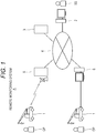
- the remote monitoring system A is a system for monitoring a working machine 1 with a monitoring terminal 2 located at a remote place.
- the working machine 1 is operated by an operator OP.
- the monitoring terminal 2 is operated by a service staff member SS.
- a plurality of the working machines 1 is involved. However, it is also possible to involve merely the one working machine 1.
- the operator OP is arranged for each working machine 1.
- the number of the monitoring terminals 2 may be either one or plural.
- the remote monitoring system A includes a server 3.
- the server 3 and the monitoring terminal 2 are connected via a network 4 such as the Internet, and can communicate with each other.
- a base station 5 for wireless communication and a data acquisition terminal 6 are connected to the network 4.
- the working machine 1 can wirelessly communicate with the base station 5. Furthermore, information held by the working machine 1 can be transmitted, directly or via a storage medium, from the working machine 1 to the data acquisition terminal 6.
- Examples of the working machine 1 include a crane, a high lift work vehicle, a road railer, and a hydraulic excavator.
- Cranes include a mobile crane and a fixed crane.
- a case of a mobile crane will be described as an example.
- a mobile crane 1 includes an overload preventing device 11, an engine control unit 15, a vehicle control device 16, a combination meter 17, an operating device 18, and a telematics controller 19.
- the overload preventing device 11 has a function of preventing an overload in consideration of stability against an overturn of the mobile crane 1 and strength of constituent members.
- the overload preventing device 11 includes a control device 12 for achieving the function.
- the control device 12 is a computer including a CPU, a memory, and the like.
- the control device 12 holds information related to the overload preventing device 11 (hereinafter referred to as "overload preventing information"). Examples of the overload preventing information include boom length, a boom hoisting angle, a working radius, a total rated load, an actual load, outrigger overhang width, and abnormal occurrence information (overload and sensor failure).
- the overload preventing device 11 includes a display device 13 and an operation panel 14.
- the display device 13 and the operation panel 14 are provided in a cab of the mobile crane 1.
- the display device 13 includes a liquid crystal display and the like, and displays the overload preventing information.
- the operator OP refers to the display device 13 mainly during crane operation.
- the operation panel 14 includes a plurality of switches and the like. The operator OP can, for example, change settings of the overload preventing device 11 by operating the operation panel 14.
- the mobile crane 1 is equipped with an engine for driving a vehicle and hydraulic equipment.
- the engine is controlled by the engine control unit 15.
- Information held by the engine control unit 15 is input to the vehicle control device 16.
- the vehicle control device 16 has a function of performing various controls of the mobile crane 1.
- the vehicle control device 16 is a computer including a CPU, a memory, and the like.
- the vehicle control device 16 holds information related to vehicle travel (hereinafter referred to as "vehicle travel information"). Examples of the vehicle travel information include vehicle speed, engine speed, traveling distance, the amount of fuel, and the temperature of engine cooling water.
- the combination meter 17 is provided in the cab of the mobile crane 1.
- the combination meter 17 displays the vehicle travel information acquired from the vehicle control device 16.
- the operator OP refers to the combination meter 17 mainly during vehicle travel.
- the operating device 18 is connected to the vehicle control device 16.
- the operating device 18 includes various switches, levers, and the like provided in the cab of the mobile crane 1.
- the operator OP can, for example, switch functions and change settings of the mobile crane 1 by operating the operating device 18.
- the telematics controller 19 has functions of collecting and storing various information of the mobile crane 1, and wirelessly transmitting the stored information to the base station 5.
- the telematics controller 19 is a computer including a CPU, a memory, and the like.
- the telematics controller 19 of the present embodiment collects and stores the overload preventing information from the control device 12 of the overload preventing device 11. Furthermore, the telematics controller 19 also collects and stores the vehicle travel information from the vehicle control device 16.
- the overload preventing information and the vehicle travel information are collectively referred to as "machine state information.”
- the machine state information includes all information representing a state of the working machine, or may include a part thereof. The machine state information is not limited to the overload preventing information and the vehicle travel information, and other information may be added thereto.
- the telematics controller 19 wirelessly transmits the stored machine state information, as necessary.
- the machine state information transmitted from the telematics controller 19 is then transmitted to the server 3 via the base station 5 and the network 4.
- the telematics controller 19 transmits the stored machine state information to the data acquisition terminal 6.
- the configuration thereof is not particularly limited.
- the telematics controller 19 and the data acquisition terminal 6 are directly connected via a USB cable or the like so as to transmit the machine state information from the telematics controller 19 to the data acquisition terminal 6.
- the telematics controller 19 may write the machine state information to a storage medium to be read by the data acquisition terminal 6.
- the data acquisition terminal 6 is a general-purpose computer.
- the machine state information acquired by the data acquisition terminal 6 is transmitted to the server 3 via the network 4.
- the display device 13 of the overload preventing device 11 and the combination meter 17 correspond to a "first display device” and a “second display device” recited in the claims, respectively.
- a "working machine display device” recited in the claims includes the display device 13 of the overload preventing device 11, as the first display device, and the combination meter 17 as the second display device.
- the working machine display device is a device for displaying the machine state information.
- the configuration of the working machine display device is not particularly limited.
- the working machine display device may be a general-purpose display device such as a liquid crystal display or a dedicated display such as the combination meter 17.
- the operation panel 14 of the overload preventing device 11 and the operating device 18 each correspond to a "working machine operating device" recited in the claims.
- the working machine operating device is a device for performing various operations of the working machine.
- the working machine operating device includes a switch, a lever, and the like, while the configuration thereof is not particularly limited.
- the display mode of the display device 13 of the overload preventing device 11 may be different depending on the working machine 1.
- the overload preventing information is displayed in different unit systems between the working machine 1 for domestic specifications and the working machine 1 for overseas specifications.
- items to be displayed may also be different depending on the model of the working machine 1.
- the display mode of the combination meter 17 may also be different depending on the working machine 1.
- the "display mode” means a mode of an information display format, which includes not only types of display formats such as graphic display and table format display, but also letters, numerals, an arrangement of graphics, display items, and others.
- the specification of the operation panel 14 of the overload preventing device 11 may be different depending on the working machine 1.
- an arrangement of switches may be different depending on the model of the working machine 1.
- the specification of the operating device 18 may also be different depending on the working machine 1.
- the monitoring terminal 2 is a general-purpose computer.
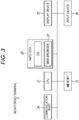
- the monitoring terminal 2 mainly includes a CPU 21, a memory 22, a hard disk 23, a communication part 24, a display device 25, and an input device 26.
- the communication part 24 has a function of connecting to the network 4 and communicating.
- the display device 25 is a liquid crystal display or the like.
- the input device 26 is a keyboard, a mouse, or the like.
- a web browser program 27 is installed on the hard disk 23. Therefore, the monitoring terminal 2 can run a web browser.
- OS operating system
- a web browser program 27 is installed on the hard disk 23. Therefore, the monitoring terminal 2 can run a web browser.
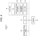
- the server 3 mainly includes a CPU 31, a memory 32, a hard disk 33, and a communication part 34.
- the communication part 34 has a function of connecting to the network 4 and communicating.
- a data collection program 35 and a data display program 36 are installed on the hard disk 33. Furthermore, in order to achieve a function as a database, a data area 37 for storing data is secured in the hard disk 33.
- a working machine master table M and a machine state information transaction table T are stored in the data area 37.
- the working machine master table M includes a working machine ID, a first display mode code, a second display mode code, a first operating device code, and a second operating device code, as data fields.
- the working machine ID is an ID for identifying the individual working machines 1. As the working machine ID, a unique value is previously assigned to each working machine 1.
- the first display mode code is a code for identifying the display mode of the display device 13 of the overload preventing device 11. As described above, the display mode of the display device 13 may be different depending on the working machine 1. As the first display mode code, for example, different values are assigned to the display mode for domestic specifications and that for overseas specifications. It should be noted that the first display mode code may be replaced with a code for identifying the specification of the overload preventing device 11.
- the second display mode code is a code for identifying the display mode of the combination meter 17.
- the display mode of the combination meter 17 may be different depending on the working machine 1.
- different values are assigned to the display mode for domestic specifications and that for overseas specifications.
- the second display mode code may be replaced with a code for identifying the specification of the combination meter 17.
- the first display mode code and the second display mode code each correspond to a "display mode code" recited in the claims.
- the display mode code may be any code as long as it identifies the display mode of the working machine display device.
- the first display mode code is associated with display part data that simulate the display mode of the display device 13 (working machine display device) of the overload preventing device 11.
- the second display mode code is associated with the display part data that simulate the display mode of the combination meter 17 (working machine display device). That is, the working machine master table M corresponds to a "first storage part" that previously stores the display part data that simulate the display mode of the working machine display device for each working machine 1.
- the first operating device code is a code for identifying the type of the operation panel 14 of the overload preventing device 11. As described above, the specification of the operation panel 14 may be different depending on the working machine 1. As the first operating device code, a unique value is assigned for each type of the operation panel 14. Incidentally, the first operating device code may be replaced with a code for identifying the specification of the overload preventing device 11.
- the second operating device code is a code for identifying the type of the operating device 18. As described above, the specification of the operating device 18 may be different depending on the working machine 1. As the second operating device code, a unique value is assigned for each type of the operating device 18.
- the first operating device code and the second operating device code correspond to the "operating device code" recited in the claims.
- the operating device code may be any code as long as it identifies the type of the working machine operating device.
- the first operating device code is associated with operating part data that simulate the arrangement mode of switches and the like on the operation panel 14 (working machine operating device) of the overload preventing device 11.
- the second operating device code is associated with the operating part data that simulate the arrangement mode of switches and the like on the operating device 18 (working machine operating device). That is, the working machine master table M corresponds to a "third storage part" that stores the operating part data that simulate the arrangement mode of switches and the like on the working machine operating device for each working machine 1.
- the working machine master table M includes the working machine ID, the first display mode code, the second display mode code, the first operating device code, and the second operating device code of the working machine 1, which are registered in advance for each working machine 1 to be monitored.
- the machine state information transaction table T includes the working machine ID, a date and time, and various items of the machine state information, as data fields.
- Items of the machine state information include items of the overload preventing information and items of the vehicle travel information. Examples of the items of the overload preventing information include boom length, a boom hoisting angle, a working radius, a total rated load, an actual load, and outrigger overhang width. Examples of the items of the vehicle travel information include vehicle speed, engine speed, traveling distance, the amount of fuel, and the temperature of engine cooling water.
- Machine state data representing the machine state information for each working machine 1 are registered in the machine state information transaction table T through data collection processing to be described below. That is, the machine state information transaction table T corresponds to a "second storage part" that sequentially stores the machine state data representing the machine state information acquired from the working machines 1.
- the server 3 stores the machine state information, the display mode code, and the operating device code of the working machine 1 in association with the working machine ID of the working machine 1.
- the CPU 31 of the server 3 performs processing to be performed in the server 3, by executing the data collection program 35.
- the machine state information is stored in the telematics controller 19 of the working machine 1.
- the telematics controller 19 wirelessly transmits the working machine ID of the working machine 1, the date and time at which the machine state information is collected, and the machine state information.
- the timing of collecting the machine state information and the timing of wirelessly transmitting the machine state information are not particularly limited.
- the machine state information may be collected and wirelessly transmitted at a timing when some problem occurs in the working machine 1, or may be collected and wirelessly transmitted on a periodic basis.
- Various data (including the machine state data) transmitted from the telematics controller 19 is then transmitted to the server 3 via the base station 5 and the network 4.
- the telematics controller 19 may transmit the stored machine state information to the data acquisition terminal 6.
- the machine state information is transmitted from the data acquisition terminal 6 to the server 3 via the network 4.
- the server 3 When the server 3 receives data including the working machine ID, the date and time, and the machine state information from the working machine 1, the server 3 adds the data to the machine state information transaction table T.
- the machine state information of the working machines 1 of various types for various dates and times is registered in the machine state information transaction table T.
- the CPU 31 of the server 3 performs processing to be performed in the server 3, by executing the data display program 36. That is, the CPU 31 functions as a display processing part for causing the display device 25 (display part) of the monitoring terminal 2 to display an image.
- the service staff member SS connects to a remote monitoring site with a web browser installed in the monitoring terminal 2 (step S11).
- the server 3 Upon connecting with the monitoring terminal 2, the server 3 invokes the data display program 36, and transmits a remote monitoring screen to the monitoring terminal 2 in HTML format or the like (step S21).
- step S21 the server 3 refers to the machine state information transaction table T, and acquires the working machine IDs and the dates and times. Then, the server 3 generates and transmits the remote monitoring screen that includes a list including the working machine IDs and the dates and times.
- the remote monitoring screen is displayed in the web browser of the monitoring terminal 2 (step S12).
- the service staff member SS can specify a particular working machine and a particular date and time from among those in the list included in the remote monitoring screen.
- the service staff member SS specifies the particular working machine and the particular date and time, the information is transmitted to the server 3 (step S13).
- the server 3 When the particular working machine and the particular date and time are specified from the monitoring terminal 2, the server 3 refers to the machine state information transaction table T, and acquires the machine state information corresponding to the working machine ID of the specified working machine and the date and time (step S22).
- the server 3 generates a display part simulated image that simulates the display mode of the working machine display device and an operating part simulated image that simulates the display mode of the working machine operating device (step S23).
- a display part simulated image that simulates the display mode of the working machine display device
- an operating part simulated image that simulates the display mode of the working machine operating device
- a display part simulated image I1 of the display device 13 of the overload preventing device 11 and an operating part simulated image I2 of the operation panel 14 of the overload preventing device 11 are generated in the following procedure.
- the server 3 refers to the working machine master table M, and acquires the first display mode code and the first operating device code corresponding to the working machine ID of the specified working machine.
- the server 3 generates the display part simulated image I1 (first display part simulated image) in which the machine state information (overload preventing information) acquired in step S22 is displayed in a display mode indicated by the first display mode code.
- the server 3 generates the operating part simulated image I2 corresponding to the first operating device code.
- the data display program 36 includes each display mode code and a simulated image generation program corresponding to each operating device code.
- the simulated image generation program includes the display part data that simulate the display mode of the working machine display device for each working machine 1 and the operating part data that simulate the arrangement mode of the switches and the like on the working machine operating device for each working machine 1.
- the server 3 executes the simulated image generation program corresponding to the acquired display mode code or operating device code, and thus generates a corresponding simulated image.
- the server 3 generates the display part simulated image that simulates the display mode of the display device 13 (working machine display device) of the overload preventing device 11, based on the display part data (display part data associated with the first display mode code) corresponding to the specified working machine 1 and the machine state data acquired from the working machine 1 (see Fig. 7 ). Specifically, the server 3 combines graphic data representing the working machine 1, included in the display part data, with the machine state data to generate the display part simulated image.
- the image data representing a crane as illustrated in Fig. 7 are graphic data.
- the server 3 generates the operating part simulated image that simulates the arrangement mode of the working machine operating device, based on the operating part data (operating part data associated with the first operating device code) corresponding to the specified working machine 1 (see Fig. 7 ).
- the display part simulated image I1 and the operating part simulated image I2 generated by the above-described processing are images as illustrated in Fig. 7 .
- the display part simulated image I1 is an image that simulates the display device 13 of the overload preventing device 11.
- the display mode of the machine state information is also simulated in the display part simulated image I1.
- the operating part simulated image I2 is an image that simulates the operation panel 14 of the overload preventing device 11.
- the server 3 may generate a simulated image I3 that reproduces another screen.
- the simulated image I3 illustrated in Fig. 8 is an image that reproduces a maintenance screen of the overload preventing device 11 (hereinafter referred to as a "maintenance simulated image").
- the machine state information includes maintenance information to be used for maintenance of the working machine 1.
- Data representing the maintenance information are stored in the machine state information transaction table T.
- a display part simulated image I4 of the combination meter 17 is generated in the following procedure.
- the server 3 refers to the working machine master table M, and acquires the second display mode code corresponding to the working machine ID of the specified working machine.
- the server 3 generates the display part simulated image I4 (second display part simulated image) in which the machine state information (vehicle travel information) acquired in step S22 is displayed in the display mode indicated by the second display mode code.
- the display part simulated image I4 generated by the above-described processing is an image as illustrated in Fig. 9 .
- a simulated image I5 of the operating device 18 is generated in the following procedure.
- the server 3 refers to the working machine master table M, and acquires the second operating device code corresponding to the working machine ID of the specified working machine.
- the server 3 generates the operating part simulated image I5 corresponding to the second operating device code.
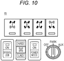
- the operating part simulated image I5 generated by the above-described processing is an image as illustrated in Fig. 10.
- Fig. 10 illustrates an example of the switches provided in the cab of the working machine 1.
- the server 3 transmits the generated simulated images I1 to I5 to the monitoring terminal 2 (step S24). Upon being transmitted from the server 3, the simulated images I1 to I5 are displayed in the web browser of the monitoring terminal 2 (step S14).
- the service staff member SS can confirm the machine state information of the specified working machine and the configuration of the working machine operating device, by referring to the simulated images I1 to I5.
- the machine state information is displayed in the monitoring terminal 2 in a display mode simulating the display mode of the working machine display device. Therefore, the operator OP of the working machine 1 and the service staff member SS on the terminal side are to see display in the same mode. As a result, the operator OP and service staff member SS can obtain common recognition, and thus communication therebetween is facilitated. For example, even if the operator OP and the service staff member SS have different native languages, it is easy for both parties to communicate.
- the service staff member SS can easily provide the operator OP with instructions on operation by telephone or e-mail.
- the server 3 may generate, in step S23, a simulated image in a mode different from that of the simulated images I1 to I5.
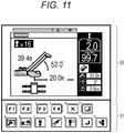
- the server 3 generates a display part simulated image I6 and an operating part simulated image 17, as illustrated in Fig. 11 .
- the display part simulated image I6 is an image that simulates the display device 13 of the overload preventing device 11.
- the display part simulated image I6 differs from the display part simulated image I1 illustrated in Fig. 7 , in the unit system and a figure representing a crane (graphic data included in the display part data).
- the display part simulated image I1 is in a display mode for domestic specifications, and the simulated image I6 is in a display mode for overseas specifications.
- the operating part simulated image I7 is an image that simulates the operation panel 14 of the overload preventing device 11.
- the operating part simulated image I7 differs from the operating part simulated image I2 illustrated in Fig.
- the operating part simulated image I2 and the operating part simulated image I7 are different images according to differences in specification of the overload preventing device 11. Specifically, the display part simulated image I1 is displayed in a unit system of the metric system, and the display part simulated image I6 is displayed in a unit system of the yard-pound system.
- the server 3 calculates values converted into the corresponding unit systems, and displays the values in the display part simulated images I1 and 16, based on the machine state data from the working machine 1.
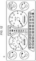
- the server 3 generates a display part simulated image I8 as illustrated in Fig. 12 .
- the display part simulated image I8 is an image that simulates the combination meter 17.
- the display part simulated image I8 differs from the display part simulated image I4 illustrated in Fig. 9 , in unit systems.
- the display part simulated image I4 is in a display mode for domestic specifications, and the display part simulated image I8 is in a display mode for overseas specifications.
- a speedometer is displayed in a unit system of the metric system (km/h).
- a speedometer is displayed in unit systems of the metric system and the yard-pound system (km/h and MPH).
- the server 3 calculates values converted into the corresponding unit systems, based on the machine state data from the working machine 1, and displays the values in the display part simulated images I4 and 18.
- the server 3 may change a display language in the display part simulated image according to a display language in each working machine 1.
- the machine state information may be displayed in a unit system and a display language selectable in the web browser of the monitoring terminal 2.
- the server 3 is connected, via a network, to the plurality of working machines 1 and the monitoring terminal 2 that includes the display device 25 (display part).
- the plurality of working machines 1 each includes the display device 13 of the overload preventing device 11 for displaying the machine state information, the combination meter 17 (working machine display device), the operation panel 14 of the overload preventing device 11 to be used for predetermined operation, and the operating device 18 (working machine operating device).
- the server 3 includes the working machine master table M (first storage part), the machine state information transaction table T (second storage part), and the CPU 31 (display processing part).
- the working machine master table M previously stores the display part data that simulate the display mode of the working machine display device for each working machine 1.
- the machine state information transaction table T sequentially stores the machine state data representing the machine state information acquired from the working machine 1.
- the CPU 31 In response to a request from the monitoring terminal 2, the CPU 31 generates the display part simulated image that simulates the display mode of the working machine display device, based on the display part data corresponding to a particular one of the working machines 1 and the machine state data acquired from the particular working machine 1, and causes the display device 25 to display the generated display part simulated image.
- the remote monitoring system A includes the working machine master table M (first storage part), the machine state information transaction table T (second storage part), the CPU 31 (display processing part) of the server 3, and the display device 25 (display part) of the monitoring terminal 2.
- the working machine master table M previously stores the display part data that simulate the display mode of the working machine display device for each working machine 1.
- the machine state information transaction table T sequentially stores the machine state data representing the machine state information acquired from the working machines 1.
- the CPU 31 generates the display part simulated image that simulates the display mode of the working machine display device, based on the display part data corresponding to the particular working machine 1 and the machine state data acquired from the particular working machine 1.
- the display device 25 displays the display part simulated image.
- the remote monitoring method in the remote monitoring system A includes steps S13, S22, S23, and S14 of Fig. 6 .
- Step S13 includes a step of acquiring and sequentially storing the machine state data representing the machine state information from each working machine 1, and a step of receiving an instruction specifying a working machine to be monitored.
- Steps S22 and S23 include a step of generating the display part simulated image that simulates the display mode of the working machine display device, based on the display part data corresponding to the specified working machine 1 to be monitored and the machine state data representing the machine state information acquired from the working machine 1 to be monitored.
- Step S14 includes a step of displaying the display part simulated image.
- the machine state information of the specified working machine 1 is displayed in the monitoring terminal 2 in the display mode indicated by the display mode code of the working machine 1. Therefore, even if the display mode of the working machine display device differs for each working machine 1, it is possible to display the machine state information of the specified working machine 1 in the monitoring terminal 2, in a display mode corresponding to the working machine. Accordingly, the operator OP and the service staff member SS can see display in the same mode.
- an image corresponding to the operating device code of the specified working machine 1 is displayed in the monitoring terminal 2. Therefore, even if the working machine operating device differs for each individual working machine 1, it is possible to display an image that simulates the working machine operating device of the specified working machine in the monitoring terminal 2. Accordingly, the service staff member SS can easily provide the operator OP with instructions on operation.
- the server 3 performs the simulated image generation processing (step S23). However, a part or all of the processing may be performed by the monitoring terminal 2.
- the monitoring terminal 2 performs the simulated image generation processing, for example, the following processing is performed.
- the server 3 transmits the working machine information acquired in step S22 to the monitoring terminal 2. Furthermore, the server 3 transmits the display mode code and the operating device code of the specified working machine to the monitoring terminal 2.
- the monitoring terminal 2 executes the preinstalled simulated image generation program to generate a simulated image.
- the monitoring terminal 2 may perform the function of the server 3. That is, a single computer may be equipped with the function of the server 3 and the function of the monitoring terminal 2.
- a web browser installed in the monitoring terminal 2 is used.
- a dedicated application may be used instead of the web browser.
- the simulated image is displayed in the monitoring terminal 2.
- the embodiment is not limited thereto.
- the machine state information just needs to be displayed in the monitoring terminal 2, in a display mode simulating the display mode of the working machine display device.
- An object to be displayed in the monitoring terminal 2 is not limited to the display device 13 of the overload preventing device 11, the combination meter 17, the operation panel 14 of the overload preventing device 11, or the operating device 18.
- a part of information held by the working machine 1 may be directly transmitted to the monitoring terminal 2 without involving the server 3, and may be displayed in the monitoring terminal 2.
- the display part simulated image and the operating part simulated image may be simultaneously displayed or selectively displayed.
- the images may be simultaneously displayed or selectively displayed.
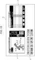
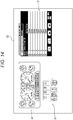
- FIGs. 13 and 14 illustrate display examples of simultaneously displaying the display part simulated image and the operating part simulated image.
- a display screen D1 illustrated in Fig. 13 includes the display part simulated image I1 that simulates the display device 13 of the overload preventing device 11, the operating part simulated image I2 that simulates the operation panel 14, and the maintenance simulated image I4 that simulates a display screen of the maintenance information, which are displayed on a single screen.
- a display screen D2 illustrated in Fig. 14 includes the display part simulated image I4 that simulates the combination meter 17, the operating part simulated image I5 that simulates the operating device 18, and the maintenance simulated image I4 that simulates the display screen of the maintenance information, which are displayed on a single screen.
- the service staff member SS can easily specify a cause of abnormal occurrence, and can provide the operator OP with more accurate instructions.
Landscapes
- Engineering & Computer Science (AREA)
- General Physics & Mathematics (AREA)
- Physics & Mathematics (AREA)
- Automation & Control Theory (AREA)
- Computer Networks & Wireless Communication (AREA)
- Signal Processing (AREA)
- Civil Engineering (AREA)
- Mining & Mineral Resources (AREA)
- General Engineering & Computer Science (AREA)
- Structural Engineering (AREA)
- Human Computer Interaction (AREA)
- Mechanical Engineering (AREA)
- Component Parts Of Construction Machinery (AREA)
- Selective Calling Equipment (AREA)
- Telephonic Communication Services (AREA)
- Testing And Monitoring For Control Systems (AREA)
Abstract
Description
- The present invention relates to a server, a remote monitoring system, and a remote monitoring method for monitoring information on a working machine with a terminal located at a remote place.
- There is known a remote monitoring system for displaying information about a working machine on a terminal located at a remote place (for example, Patent Literature 1). When some problem occurs in a working machine, a remote monitoring system of this type is used for solving the problem while an operator of the working machine and a service staff member on a terminal side communicate by telephone or e-mail, and share information on the working machine.
- However, in the conventional remote monitoring system, a display format of a display device mounted on the working machine differs from that of the terminal side. For example, information is graphically displayed on the display device of the working machine, while information is displayed in the terminal in tabular form. Therefore, it is difficult for the operator of the working machine to communicate with the service staff member on the terminal side, and thus it takes time to solve the problem.
- Patent Literature 1:
JP 2013-161192 A - An object of the present invention is to provide a server, a remote monitoring system, and a remote monitoring method capable of facilitating communication between an operator of a working machine and a service staff member on a terminal side.
- A server according to the present invention is a server configured to be used for maintenance, the server being connected, via a network, to a plurality of working machines each including a working machine display device that displays machine state information and a working machine operating device to be used for predetermined operation, and to a monitoring terminal that includes a display part and remotely monitors information on the working machines,
wherein communication between each of the plurality of working machines and the server is one-way communication from the working machines to the server,
the server including: - a first storage part that previously stores display part data that simulate a display mode of the working machine display device for each of the working machines;
- a second storage part that sequentially stores machine state data representing the machine state information acquired from the working machines; and
- a display processing part that, in response to a request from the monitoring terminal, generates a display part simulated image, which simulates the display mode of the working machine display device, based on the display part data corresponding to a specific one of the working machines and the machine state data acquired from the specific working machine, and causes the display part to display a maintenance screen including the display part simulated image.
- A remote monitoring system according to the present invention is a remote monitoring system connected, via a network, to a plurality of working machines each including a working machine display device that displays machine state information and a working machine operating device to be used for predetermined operation, the remote monitoring system including:
- a communication part that acquires information from each of the plurality of working machines through one-way communication;
- a first storage part that previously stores display part data that simulate a display mode of the working machine display device for each of the working machines;
- a second storage part that sequentially stores machine state data representing the machine state information acquired from the working machines;
- a display processing part that generates a display part simulated image, which simulates the display mode of the working machine display device, based on the display part data corresponding to a specific one of the working machines and the machine state data acquired from the specific working machine; and
- a display part that displays a maintenance screen including the display part simulated image.
- A remote monitoring method in a remote monitoring system connected, via a network, to a plurality of working machines each including a working machine display device that displays machine state information and a working machine operating device to be used for predetermined operation, the remote monitoring system including display part data that simulate a display mode of the working machine display device for each of the working machines, the remote monitoring method including:
- a step of acquiring information from each of the plurality of working machines through one-way communication;
- a step of acquiring machine state data representing the machine state information from each of the working machines, and sequentially storing the data;
- a step of receiving an instruction specifying one of the working machines to be monitored;
- a step of generating a display part simulated image that simulates the display mode of the working machine display device, based on the display part data corresponding to the specified working machine to be monitored and the machine state data representing the machine state information acquired from the working machine to be monitored; and
- a step of displaying a maintenance screen including the display part simulated image.
- According to the present invention, since the display part simulated image that simulates the display mode of the working machine display device is displayed on the display part, an operator of the working machine and a service staff member on the terminal side can obtain common recognition, and thus communication therebetween is facilitated.
-
-
Fig. 1 is an entire configuration diagram of a remote monitoring system according to one embodiment of the present invention. -
Fig. 2 is a block diagram of a mobile crane. -
Fig. 3 is a hardware configuration diagram of a monitoring terminal. -
Fig. 4 is a hardware configuration diagram of a server. -
Fig. 5 is an explanatory diagram of a database configuration. -
Fig. 6 is a flowchart of data display processing. -
Fig. 7 is an explanatory diagram of a simulated image of a display device of an overload preventing device and a simulated image of an operation panel of the overload preventing device. -
Fig. 8 is an explanatory diagram of a simulated image of a display device of an overload preventing device and a simulated image of an operation panel of the overload preventing device in another embodiment. -
Fig. 9 is an explanatory diagram of a simulated image of a combination meter. -
Fig. 10 is an explanatory diagram of a simulated image of an operating device. -
Fig. 11 is an explanatory diagram of a simulated image of a display device of an overload preventing device and a simulated image of an operation panel of the overload preventing device in still another embodiment. -
Fig. 12 is an explanatory diagram of a simulated image of a combination meter in another embodiment. -
Fig. 13 illustrates an example of displaying a display part simulated image, an operating part simulated image, and a maintenance simulated image on a single screen. -
Fig. 14 illustrates another example of displaying a display part simulated image, an operating part simulated image, and a maintenance simulated image on a single screen. - Next, embodiments of the present invention will be described with reference to the drawings.
- First, an entire configuration of a remote monitoring system A according to one embodiment of the present invention will be described.
- As illustrated in
Fig. 1 , the remote monitoring system A is a system for monitoring a workingmachine 1 with amonitoring terminal 2 located at a remote place. The workingmachine 1 is operated by an operator OP. Themonitoring terminal 2 is operated by a service staff member SS. Generally, a plurality of theworking machines 1 is involved. However, it is also possible to involve merely the one workingmachine 1. The operator OP is arranged for eachworking machine 1. The number of themonitoring terminals 2 may be either one or plural. - The remote monitoring system A includes a
server 3. Theserver 3 and themonitoring terminal 2 are connected via anetwork 4 such as the Internet, and can communicate with each other. Abase station 5 for wireless communication and adata acquisition terminal 6 are connected to thenetwork 4. The workingmachine 1 can wirelessly communicate with thebase station 5. Furthermore, information held by the workingmachine 1 can be transmitted, directly or via a storage medium, from theworking machine 1 to thedata acquisition terminal 6. - Next, the working
machine 1 will be described. - Examples of the working
machine 1 include a crane, a high lift work vehicle, a road railer, and a hydraulic excavator. Cranes include a mobile crane and a fixed crane. Hereinafter, a case of a mobile crane will be described as an example. - As illustrated in
Fig. 2 , amobile crane 1 includes anoverload preventing device 11, anengine control unit 15, avehicle control device 16, acombination meter 17, an operatingdevice 18, and atelematics controller 19. - The
overload preventing device 11 has a function of preventing an overload in consideration of stability against an overturn of themobile crane 1 and strength of constituent members. Theoverload preventing device 11 includes acontrol device 12 for achieving the function. Thecontrol device 12 is a computer including a CPU, a memory, and the like. Thecontrol device 12 holds information related to the overload preventing device 11 (hereinafter referred to as "overload preventing information"). Examples of the overload preventing information include boom length, a boom hoisting angle, a working radius, a total rated load, an actual load, outrigger overhang width, and abnormal occurrence information (overload and sensor failure). - The
overload preventing device 11 includes adisplay device 13 and anoperation panel 14. Thedisplay device 13 and theoperation panel 14 are provided in a cab of themobile crane 1. Thedisplay device 13 includes a liquid crystal display and the like, and displays the overload preventing information. The operator OP refers to thedisplay device 13 mainly during crane operation. Theoperation panel 14 includes a plurality of switches and the like. The operator OP can, for example, change settings of theoverload preventing device 11 by operating theoperation panel 14. - The
mobile crane 1 is equipped with an engine for driving a vehicle and hydraulic equipment. The engine is controlled by theengine control unit 15. Information held by theengine control unit 15 is input to thevehicle control device 16. - The
vehicle control device 16 has a function of performing various controls of themobile crane 1. Thevehicle control device 16 is a computer including a CPU, a memory, and the like. Thevehicle control device 16 holds information related to vehicle travel (hereinafter referred to as "vehicle travel information"). Examples of the vehicle travel information include vehicle speed, engine speed, traveling distance, the amount of fuel, and the temperature of engine cooling water. - The
combination meter 17 is provided in the cab of themobile crane 1. Thecombination meter 17 displays the vehicle travel information acquired from thevehicle control device 16. The operator OP refers to thecombination meter 17 mainly during vehicle travel. - The operating
device 18 is connected to thevehicle control device 16. The operatingdevice 18 includes various switches, levers, and the like provided in the cab of themobile crane 1. The operator OP can, for example, switch functions and change settings of themobile crane 1 by operating the operatingdevice 18. - The
telematics controller 19 has functions of collecting and storing various information of themobile crane 1, and wirelessly transmitting the stored information to thebase station 5. Thetelematics controller 19 is a computer including a CPU, a memory, and the like. - The
telematics controller 19 of the present embodiment collects and stores the overload preventing information from thecontrol device 12 of theoverload preventing device 11. Furthermore, thetelematics controller 19 also collects and stores the vehicle travel information from thevehicle control device 16. Hereinafter, the overload preventing information and the vehicle travel information are collectively referred to as "machine state information." The machine state information includes all information representing a state of the working machine, or may include a part thereof. The machine state information is not limited to the overload preventing information and the vehicle travel information, and other information may be added thereto. - For example, the
telematics controller 19 wirelessly transmits the stored machine state information, as necessary. The machine state information transmitted from thetelematics controller 19 is then transmitted to theserver 3 via thebase station 5 and thenetwork 4. - Moreover, for example, the
telematics controller 19 transmits the stored machine state information to thedata acquisition terminal 6. The configuration thereof is not particularly limited. For example, thetelematics controller 19 and thedata acquisition terminal 6 are directly connected via a USB cable or the like so as to transmit the machine state information from thetelematics controller 19 to thedata acquisition terminal 6. Thetelematics controller 19 may write the machine state information to a storage medium to be read by thedata acquisition terminal 6. - The
data acquisition terminal 6 is a general-purpose computer. The machine state information acquired by thedata acquisition terminal 6 is transmitted to theserver 3 via thenetwork 4. - The
display device 13 of theoverload preventing device 11 and thecombination meter 17 correspond to a "first display device" and a "second display device" recited in the claims, respectively. In addition, a "working machine display device" recited in the claims includes thedisplay device 13 of theoverload preventing device 11, as the first display device, and thecombination meter 17 as the second display device. The working machine display device is a device for displaying the machine state information. The configuration of the working machine display device is not particularly limited. The working machine display device may be a general-purpose display device such as a liquid crystal display or a dedicated display such as thecombination meter 17. - The
operation panel 14 of theoverload preventing device 11 and the operatingdevice 18 each correspond to a "working machine operating device" recited in the claims. The working machine operating device is a device for performing various operations of the working machine. The working machine operating device includes a switch, a lever, and the like, while the configuration thereof is not particularly limited. - The display mode of the
display device 13 of theoverload preventing device 11 may be different depending on the workingmachine 1. For example, the overload preventing information is displayed in different unit systems between the workingmachine 1 for domestic specifications and the workingmachine 1 for overseas specifications. In addition, items to be displayed may also be different depending on the model of the workingmachine 1. Similarly, the display mode of thecombination meter 17 may also be different depending on the workingmachine 1. - It should be noted that in the present specification, the "display mode" means a mode of an information display format, which includes not only types of display formats such as graphic display and table format display, but also letters, numerals, an arrangement of graphics, display items, and others.
- The specification of the
operation panel 14 of theoverload preventing device 11 may be different depending on the workingmachine 1. For example, an arrangement of switches may be different depending on the model of the workingmachine 1. Similarly, the specification of the operatingdevice 18 may also be different depending on the workingmachine 1. - Next, the hardware configuration of the
monitoring terminal 2 will be described. - As illustrated in
Fig. 3 , themonitoring terminal 2 is a general-purpose computer. Themonitoring terminal 2 mainly includes aCPU 21, amemory 22, ahard disk 23, acommunication part 24, adisplay device 25, and aninput device 26. Thecommunication part 24 has a function of connecting to thenetwork 4 and communicating. Thedisplay device 25 is a liquid crystal display or the like. Theinput device 26 is a keyboard, a mouse, or the like. - In addition to an operating system (OS), a
web browser program 27 is installed on thehard disk 23. Therefore, themonitoring terminal 2 can run a web browser. - Next, the hardware configuration of the
server 3 will be described. - As illustrated in
Fig. 4 , theserver 3 mainly includes aCPU 31, amemory 32, ahard disk 33, and acommunication part 34. Thecommunication part 34 has a function of connecting to thenetwork 4 and communicating. - In addition to an operating system (OS), a
data collection program 35 and adata display program 36 are installed on thehard disk 33. Furthermore, in order to achieve a function as a database, adata area 37 for storing data is secured in thehard disk 33. - Next, a database configuration will be described.
- As illustrated in
Fig. 5 , a working machine master table M and a machine state information transaction table T are stored in thedata area 37. - The working machine master table M includes a working machine ID, a first display mode code, a second display mode code, a first operating device code, and a second operating device code, as data fields. The working machine ID is an ID for identifying the
individual working machines 1. As the working machine ID, a unique value is previously assigned to each workingmachine 1. - The first display mode code is a code for identifying the display mode of the
display device 13 of theoverload preventing device 11. As described above, the display mode of thedisplay device 13 may be different depending on the workingmachine 1. As the first display mode code, for example, different values are assigned to the display mode for domestic specifications and that for overseas specifications. It should be noted that the first display mode code may be replaced with a code for identifying the specification of theoverload preventing device 11. - The second display mode code is a code for identifying the display mode of the
combination meter 17. As described above, the display mode of thecombination meter 17 may be different depending on the workingmachine 1. As the second display mode code, for example, different values are assigned to the display mode for domestic specifications and that for overseas specifications. It should be noted that the second display mode code may be replaced with a code for identifying the specification of thecombination meter 17. - The first display mode code and the second display mode code each correspond to a "display mode code" recited in the claims. The display mode code may be any code as long as it identifies the display mode of the working machine display device.
- The first display mode code is associated with display part data that simulate the display mode of the display device 13 (working machine display device) of the
overload preventing device 11. In addition, the second display mode code is associated with the display part data that simulate the display mode of the combination meter 17 (working machine display device). That is, the working machine master table M corresponds to a "first storage part" that previously stores the display part data that simulate the display mode of the working machine display device for each workingmachine 1. - The first operating device code is a code for identifying the type of the
operation panel 14 of theoverload preventing device 11. As described above, the specification of theoperation panel 14 may be different depending on the workingmachine 1. As the first operating device code, a unique value is assigned for each type of theoperation panel 14. Incidentally, the first operating device code may be replaced with a code for identifying the specification of theoverload preventing device 11. - The second operating device code is a code for identifying the type of the operating
device 18. As described above, the specification of the operatingdevice 18 may be different depending on the workingmachine 1. As the second operating device code, a unique value is assigned for each type of the operatingdevice 18. - The first operating device code and the second operating device code correspond to the "operating device code" recited in the claims. The operating device code may be any code as long as it identifies the type of the working machine operating device.
- The first operating device code is associated with operating part data that simulate the arrangement mode of switches and the like on the operation panel 14 (working machine operating device) of the
overload preventing device 11. In addition, the second operating device code is associated with the operating part data that simulate the arrangement mode of switches and the like on the operating device 18 (working machine operating device). That is, the working machine master table M corresponds to a "third storage part" that stores the operating part data that simulate the arrangement mode of switches and the like on the working machine operating device for each workingmachine 1. - The working machine master table M includes the working machine ID, the first display mode code, the second display mode code, the first operating device code, and the second operating device code of the working
machine 1, which are registered in advance for each workingmachine 1 to be monitored. - The machine state information transaction table T includes the working machine ID, a date and time, and various items of the machine state information, as data fields. Items of the machine state information include items of the overload preventing information and items of the vehicle travel information. Examples of the items of the overload preventing information include boom length, a boom hoisting angle, a working radius, a total rated load, an actual load, and outrigger overhang width. Examples of the items of the vehicle travel information include vehicle speed, engine speed, traveling distance, the amount of fuel, and the temperature of engine cooling water.
- Machine state data representing the machine state information for each working
machine 1 are registered in the machine state information transaction table T through data collection processing to be described below. That is, the machine state information transaction table T corresponds to a "second storage part" that sequentially stores the machine state data representing the machine state information acquired from the workingmachines 1. - As described above, the
server 3 stores the machine state information, the display mode code, and the operating device code of the workingmachine 1 in association with the working machine ID of the workingmachine 1. - Next, data acquisition processing will be described.
- As a part of the data acquisition processing, the
CPU 31 of theserver 3 performs processing to be performed in theserver 3, by executing thedata collection program 35. - The machine state information is stored in the
telematics controller 19 of the workingmachine 1. Thetelematics controller 19 wirelessly transmits the working machine ID of the workingmachine 1, the date and time at which the machine state information is collected, and the machine state information. Here, the timing of collecting the machine state information and the timing of wirelessly transmitting the machine state information are not particularly limited. The machine state information may be collected and wirelessly transmitted at a timing when some problem occurs in the workingmachine 1, or may be collected and wirelessly transmitted on a periodic basis. Various data (including the machine state data) transmitted from thetelematics controller 19 is then transmitted to theserver 3 via thebase station 5 and thenetwork 4. - Furthermore, the
telematics controller 19 may transmit the stored machine state information to thedata acquisition terminal 6. In this case, the machine state information is transmitted from thedata acquisition terminal 6 to theserver 3 via thenetwork 4. - When the
server 3 receives data including the working machine ID, the date and time, and the machine state information from the workingmachine 1, theserver 3 adds the data to the machine state information transaction table T. - With the repetition of the above-described processing, the machine state information of the working
machines 1 of various types for various dates and times is registered in the machine state information transaction table T. - Next, data display processing will be described with reference to
Fig 6 . - As a part of the data display processing, the
CPU 31 of theserver 3 performs processing to be performed in theserver 3, by executing thedata display program 36. That is, theCPU 31 functions as a display processing part for causing the display device 25 (display part) of themonitoring terminal 2 to display an image. - First, the service staff member SS connects to a remote monitoring site with a web browser installed in the monitoring terminal 2 (step S11). Upon connecting with the
monitoring terminal 2, theserver 3 invokes thedata display program 36, and transmits a remote monitoring screen to themonitoring terminal 2 in HTML format or the like (step S21). - In step S21, the
server 3 refers to the machine state information transaction table T, and acquires the working machine IDs and the dates and times. Then, theserver 3 generates and transmits the remote monitoring screen that includes a list including the working machine IDs and the dates and times. - Upon being transmitted from the
server 3, the remote monitoring screen is displayed in the web browser of the monitoring terminal 2 (step S12). The service staff member SS can specify a particular working machine and a particular date and time from among those in the list included in the remote monitoring screen. When the service staff member SS specifies the particular working machine and the particular date and time, the information is transmitted to the server 3 (step S13). - When the particular working machine and the particular date and time are specified from the
monitoring terminal 2, theserver 3 refers to the machine state information transaction table T, and acquires the machine state information corresponding to the working machine ID of the specified working machine and the date and time (step S22). - Next, the
server 3 generates a display part simulated image that simulates the display mode of the working machine display device and an operating part simulated image that simulates the display mode of the working machine operating device (step S23). Hereinafter, various simulated images will be described in order. - A display part simulated image I1 of the
display device 13 of theoverload preventing device 11 and an operating part simulated image I2 of theoperation panel 14 of theoverload preventing device 11 are generated in the following procedure. - First, the
server 3 refers to the working machine master table M, and acquires the first display mode code and the first operating device code corresponding to the working machine ID of the specified working machine. Next, theserver 3 generates the display part simulated image I1 (first display part simulated image) in which the machine state information (overload preventing information) acquired in step S22 is displayed in a display mode indicated by the first display mode code. In addition, theserver 3 generates the operating part simulated image I2 corresponding to the first operating device code. - Here, the
data display program 36 includes each display mode code and a simulated image generation program corresponding to each operating device code. The simulated image generation program includes the display part data that simulate the display mode of the working machine display device for each workingmachine 1 and the operating part data that simulate the arrangement mode of the switches and the like on the working machine operating device for each workingmachine 1. Theserver 3 executes the simulated image generation program corresponding to the acquired display mode code or operating device code, and thus generates a corresponding simulated image. - That is, the
server 3 generates the display part simulated image that simulates the display mode of the display device 13 (working machine display device) of theoverload preventing device 11, based on the display part data (display part data associated with the first display mode code) corresponding to the specified workingmachine 1 and the machine state data acquired from the working machine 1 (seeFig. 7 ). Specifically, theserver 3 combines graphic data representing the workingmachine 1, included in the display part data, with the machine state data to generate the display part simulated image. The image data representing a crane as illustrated inFig. 7 are graphic data. - Furthermore, the
server 3 generates the operating part simulated image that simulates the arrangement mode of the working machine operating device, based on the operating part data (operating part data associated with the first operating device code) corresponding to the specified working machine 1 (seeFig. 7 ). - The display part simulated image I1 and the operating part simulated image I2 generated by the above-described processing are images as illustrated in
Fig. 7 . The display part simulated image I1 is an image that simulates thedisplay device 13 of theoverload preventing device 11. The display mode of the machine state information is also simulated in the display part simulated image I1. The operating part simulated image I2 is an image that simulates theoperation panel 14 of theoverload preventing device 11. - While the display part simulated image I1 reproduces a normal screen of the
overload preventing device 11, theserver 3 may generate a simulated image I3 that reproduces another screen. The simulated image I3 illustrated inFig. 8 is an image that reproduces a maintenance screen of the overload preventing device 11 (hereinafter referred to as a "maintenance simulated image"). In this case, the machine state information includes maintenance information to be used for maintenance of the workingmachine 1. Data representing the maintenance information are stored in the machine state information transaction table T. - A display part simulated image I4 of the
combination meter 17 is generated in the following procedure. - First, the
server 3 refers to the working machine master table M, and acquires the second display mode code corresponding to the working machine ID of the specified working machine. Next, theserver 3 generates the display part simulated image I4 (second display part simulated image) in which the machine state information (vehicle travel information) acquired in step S22 is displayed in the display mode indicated by the second display mode code. The display part simulated image I4 generated by the above-described processing is an image as illustrated inFig. 9 . - A simulated image I5 of the operating
device 18 is generated in the following procedure. - First, the
server 3 refers to the working machine master table M, and acquires the second operating device code corresponding to the working machine ID of the specified working machine. Next, theserver 3 generates the operating part simulated image I5 corresponding to the second operating device code. The operating part simulated image I5 generated by the above-described processing is an image as illustrated inFig. 10. Fig. 10 illustrates an example of the switches provided in the cab of the workingmachine 1. - Returning to
Fig. 6 , description will be continued. Theserver 3 transmits the generated simulated images I1 to I5 to the monitoring terminal 2 (step S24). Upon being transmitted from theserver 3, the simulated images I1 to I5 are displayed in the web browser of the monitoring terminal 2 (step S14). The service staff member SS can confirm the machine state information of the specified working machine and the configuration of the working machine operating device, by referring to the simulated images I1 to I5. - As described above, the machine state information is displayed in the
monitoring terminal 2 in a display mode simulating the display mode of the working machine display device. Therefore, the operator OP of the workingmachine 1 and the service staff member SS on the terminal side are to see display in the same mode. As a result, the operator OP and service staff member SS can obtain common recognition, and thus communication therebetween is facilitated. For example, even if the operator OP and the service staff member SS have different native languages, it is easy for both parties to communicate. - Furthermore, an image that simulates the working machine operating device is displayed in the
monitoring terminal 2. Therefore, the service staff member SS can easily provide the operator OP with instructions on operation by telephone or e-mail. - Even if some problem occurs in the working
machine 1, the problem can be solved at an early stage since the operator OP and the service staff member SS can easily communicate. As a result, it is possible to reduce downtime of the workingmachine 1. - Incidentally, when the service staff member SS specifies another working machine in step S13, the
server 3 may generate, in step S23, a simulated image in a mode different from that of the simulated images I1 to I5. - For example, the
server 3 generates a display part simulated image I6 and an operating partsimulated image 17, as illustrated inFig. 11 . The display part simulated image I6 is an image that simulates thedisplay device 13 of theoverload preventing device 11. The display part simulated image I6 differs from the display part simulated image I1 illustrated inFig. 7 , in the unit system and a figure representing a crane (graphic data included in the display part data). The display part simulated image I1 is in a display mode for domestic specifications, and the simulated image I6 is in a display mode for overseas specifications. The operating part simulated image I7 is an image that simulates theoperation panel 14 of theoverload preventing device 11. The operating part simulated image I7 differs from the operating part simulated image I2 illustrated inFig. 7 in the arrangement of switches. The operating part simulated image I2 and the operating part simulated image I7 are different images according to differences in specification of theoverload preventing device 11. Specifically, the display part simulated image I1 is displayed in a unit system of the metric system, and the display part simulated image I6 is displayed in a unit system of the yard-pound system. Theserver 3 calculates values converted into the corresponding unit systems, and displays the values in the display part simulated images I1 and 16, based on the machine state data from the workingmachine 1. - In addition, the
server 3 generates a display part simulated image I8 as illustrated inFig. 12 . The display part simulated image I8 is an image that simulates thecombination meter 17. The display part simulated image I8 differs from the display part simulated image I4 illustrated inFig. 9 , in unit systems. The display part simulated image I4 is in a display mode for domestic specifications, and the display part simulated image I8 is in a display mode for overseas specifications. Specifically, in the display partsimulated image 14, a speedometer is displayed in a unit system of the metric system (km/h). In the display partsimulated image 18, a speedometer is displayed in unit systems of the metric system and the yard-pound system (km/h and MPH). Theserver 3 calculates values converted into the corresponding unit systems, based on the machine state data from the workingmachine 1, and displays the values in the display part simulated images I4 and 18. - It should be noted that when text information is included in the machine state information, the
server 3 may change a display language in the display part simulated image according to a display language in each workingmachine 1. In addition, the machine state information may be displayed in a unit system and a display language selectable in the web browser of themonitoring terminal 2. - As described above, the
server 3 according to the embodiment is connected, via a network, to the plurality of workingmachines 1 and themonitoring terminal 2 that includes the display device 25 (display part). The plurality of workingmachines 1 each includes thedisplay device 13 of theoverload preventing device 11 for displaying the machine state information, the combination meter 17 (working machine display device), theoperation panel 14 of theoverload preventing device 11 to be used for predetermined operation, and the operating device 18 (working machine operating device). Theserver 3 includes the working machine master table M (first storage part), the machine state information transaction table T (second storage part), and the CPU 31 (display processing part). The working machine master table M previously stores the display part data that simulate the display mode of the working machine display device for each workingmachine 1. The machine state information transaction table T sequentially stores the machine state data representing the machine state information acquired from the workingmachine 1. In response to a request from themonitoring terminal 2, theCPU 31 generates the display part simulated image that simulates the display mode of the working machine display device, based on the display part data corresponding to a particular one of the workingmachines 1 and the machine state data acquired from the particular workingmachine 1, and causes thedisplay device 25 to display the generated display part simulated image. - The remote monitoring system A according to the embodiment includes the working machine master table M (first storage part), the machine state information transaction table T (second storage part), the CPU 31 (display processing part) of the
server 3, and the display device 25 (display part) of themonitoring terminal 2. The working machine master table M previously stores the display part data that simulate the display mode of the working machine display device for each workingmachine 1. The machine state information transaction table T sequentially stores the machine state data representing the machine state information acquired from the workingmachines 1. TheCPU 31 generates the display part simulated image that simulates the display mode of the working machine display device, based on the display part data corresponding to the particular workingmachine 1 and the machine state data acquired from the particular workingmachine 1. Thedisplay device 25 displays the display part simulated image. - The remote monitoring method in the remote monitoring system A according to the embodiment includes steps S13, S22, S23, and S14 of
Fig. 6 . Step S13 includes a step of acquiring and sequentially storing the machine state data representing the machine state information from each workingmachine 1, and a step of receiving an instruction specifying a working machine to be monitored. Steps S22 and S23 include a step of generating the display part simulated image that simulates the display mode of the working machine display device, based on the display part data corresponding to the specified workingmachine 1 to be monitored and the machine state data representing the machine state information acquired from the workingmachine 1 to be monitored. Step S14 includes a step of displaying the display part simulated image. - As described above, the machine state information of the specified working
machine 1 is displayed in themonitoring terminal 2 in the display mode indicated by the display mode code of the workingmachine 1. Therefore, even if the display mode of the working machine display device differs for each workingmachine 1, it is possible to display the machine state information of the specified workingmachine 1 in themonitoring terminal 2, in a display mode corresponding to the working machine. Accordingly, the operator OP and the service staff member SS can see display in the same mode. - In addition, an image corresponding to the operating device code of the specified working
machine 1 is displayed in themonitoring terminal 2. Therefore, even if the working machine operating device differs for each individual workingmachine 1, it is possible to display an image that simulates the working machine operating device of the specified working machine in themonitoring terminal 2. Accordingly, the service staff member SS can easily provide the operator OP with instructions on operation. - In the above-described embodiment, the
server 3 performs the simulated image generation processing (step S23). However, a part or all of the processing may be performed by themonitoring terminal 2. When themonitoring terminal 2 performs the simulated image generation processing, for example, the following processing is performed. Theserver 3 transmits the working machine information acquired in step S22 to themonitoring terminal 2. Furthermore, theserver 3 transmits the display mode code and the operating device code of the specified working machine to themonitoring terminal 2. Themonitoring terminal 2 executes the preinstalled simulated image generation program to generate a simulated image. - The
monitoring terminal 2 may perform the function of theserver 3. That is, a single computer may be equipped with the function of theserver 3 and the function of themonitoring terminal 2. - In the above-described embodiment, a web browser installed in the
monitoring terminal 2 is used. However, a dedicated application may be used instead of the web browser. - In the above-described embodiment, the simulated image is displayed in the
monitoring terminal 2. However, the embodiment is not limited thereto. The machine state information just needs to be displayed in themonitoring terminal 2, in a display mode simulating the display mode of the working machine display device. - An object to be displayed in the
monitoring terminal 2 is not limited to thedisplay device 13 of theoverload preventing device 11, thecombination meter 17, theoperation panel 14 of theoverload preventing device 11, or the operatingdevice 18. - A part of information held by the working
machine 1 may be directly transmitted to themonitoring terminal 2 without involving theserver 3, and may be displayed in themonitoring terminal 2. - Furthermore, the display part simulated image and the operating part simulated image may be simultaneously displayed or selectively displayed. Moreover, when there are plural types of display part simulated images or operating part simulated images, the images may be simultaneously displayed or selectively displayed.
-
Figs. 13 and14 illustrate display examples of simultaneously displaying the display part simulated image and the operating part simulated image. A display screen D1 illustrated inFig. 13 includes the display part simulated image I1 that simulates thedisplay device 13 of theoverload preventing device 11, the operating part simulated image I2 that simulates theoperation panel 14, and the maintenance simulated image I4 that simulates a display screen of the maintenance information, which are displayed on a single screen. A display screen D2 illustrated inFig. 14 includes the display part simulated image I4 that simulates thecombination meter 17, the operating part simulated image I5 that simulates the operatingdevice 18, and the maintenance simulated image I4 that simulates the display screen of the maintenance information, which are displayed on a single screen. As the maintenance simulated image is displayed together with the display part simulated image and/or the operating part simulated image, the service staff member SS can easily specify a cause of abnormal occurrence, and can provide the operator OP with more accurate instructions. - The disclosures in the descriptions, drawings and abstracts included in Japanese Patent Application No.
2016-18052 filed on February 2, 2016 2016-219933 filed on November 10, 2016 -
- A remote monitoring system
- 1 working machine
- 2 monitoring terminal
- 3 server
- 4 network
- 5 base station
- 6 data acquisition terminal
- 11 overload preventing device
- 12 control device
- 13 display device (working machine display device and first display device)
- 14 operation panel (working machine operating device)
- 15 engine control unit
- 16 vehicle control device
- 17 combination meter (working machine display device and second display device)
- 18 operating device (working machine operating device)
- 19 telematics controller
- 31 CPU (display processing part)
- M working machine master table (first storage part and third storage part)
- T machine state information transaction table (second storage part)
Claims (10)
- A server configured to be used for maintenance, the server being connected, via a network, to a plurality of working machines each including a working machine display device that displays machine state information and a working machine operating device to be used for predetermined operation, and to a monitoring terminal that includes a display part and remotely monitors information on the working machines,
wherein communication between each of the plurality of working machines and the server is one-way communication from the working machines to the server,
the server comprising:a first storage part that previously stores display part data that simulate a display mode of the working machine display device for each of the working machines;a second storage part that sequentially stores machine state data representing the machine state information acquired from the working machines; anda display processing part that, in response to a request from the monitoring terminal, generates a display part simulated image, which simulates the display mode of the working machine display device, based on the display part data corresponding to a specific one of the working machines and the machine state data acquired from the specific working machine, and causes the display part to display a maintenance screen including the display part simulated image. - The server according to claim 1, further comprising:a third storage part that stores operating part data that simulate an arrangement mode of switches and the like on the working machine operating device for each of the working machines,wherein the display processing part generates an operating part simulated image that simulates the arrangement mode of the working machine operating device, based on the operating part data, and causes the display part to display the operating part simulated image together with the display part simulated image.
- The server according to claim 2, wherein
the third storage part stores an operating device code for identifying a type of the working machine operating device, in association with a working machine ID for identifying the working machine. - The server according to claim 1, wherein
the first storage part stores a display mode code for identifying the display mode of the working machine display device, in association with the working machine ID for identifying the working machine, and
the second storage part stores the machine state information in association with the working machine ID. - The server according to claim 1, wherein
the display part data includes graphic data representing the working machine, and
the display processing part generates the display part simulated image by combining the graphic data and the machine state data. - The server according to claim 1, wherein
the machine state information includes maintenance information to be used for maintenance of the working machine, and
the display processing part causes the display part to simultaneously or selectively display the display part simulated image and the corresponding maintenance information. - The server according to claim 1, wherein
the machine state information includes overload preventing information for prevention of an overload state in the working machine, and vehicle travel information on travel of the working machine,
the working machine display device includes a first display device that displays the overload preventing information, and a second display device that displays the vehicle travel information, and
the display processing part causes the display part to simultaneously or selectively display a first display part simulated image that simulates a display mode of the first display device, and a second display part simulated image that simulates a display mode of the second display device. - The server according to claim 1, wherein
the display part data includes data relating to a display language or unit system used in the working machine display device, and
the display processing part switches display of the machine state information in the display part simulated image, based on the data relating to the display language or the unit system. - A remote monitoring system connected, via a network, to a plurality of working machines each including a working machine display device that displays machine state information and a working machine operating device to be used for predetermined operation, the remote monitoring system comprising:a communication part that acquires information from each of the plurality of working machines through one-way communication;a first storage part that previously stores display part data that simulate a display mode of the working machine display device for each of the working machines;a second storage part that sequentially stores machine state data representing the machine state information acquired from the working machines;a display processing part that generates a display part simulated image, which simulates the display mode of the working machine display device, based on the display part data corresponding to a specific one of the working machines and the machine state data acquired from the specific working machine; anda display part that displays a maintenance screen including the display part simulated image.
- A remote monitoring method in a remote monitoring system connected, via a network, to a plurality of working machines each including a working machine display device that displays machine state information and a working machine operating device to be used for predetermined operation, the remote monitoring system including display part data that simulate a display mode of the working machine display device for each of the working machines, the remote monitoring method comprising:a step of acquiring information from each of the plurality of working machines through one-way communication;a step of acquiring machine state data representing the machine state information from each of the working machines, and sequentially storing the machine state data;a step of receiving an instruction specifying one of the working machines to be monitored;a step of generating a display part simulated image that simulates the display mode of the working machine display device, based on the display part data corresponding to the specified working machine to be monitored and the machine state data representing the machine state information acquired from the working machine to be monitored; anda step of displaying a maintenance screen including the display part simulated image.
Applications Claiming Priority (3)
| Application Number | Priority Date | Filing Date | Title |
|---|---|---|---|
| JP2016018052 | 2016-02-02 | ||
| JP2016219933A JP6147406B1 (en) | 2016-02-02 | 2016-11-10 | Server, remote monitoring system and remote monitoring method |
| PCT/JP2017/003825 WO2017135380A1 (en) | 2016-02-02 | 2017-02-02 | Server, remote monitoring system, and remote monitoring method |
Publications (3)
| Publication Number | Publication Date |
|---|---|
| EP3413578A1 true EP3413578A1 (en) | 2018-12-12 |
| EP3413578A4 EP3413578A4 (en) | 2019-08-28 |
| EP3413578B1 EP3413578B1 (en) | 2023-10-11 |
Family
ID=59061224
Family Applications (1)
| Application Number | Title | Priority Date | Filing Date |
|---|---|---|---|
| EP17747531.6A Active EP3413578B1 (en) | 2016-02-02 | 2017-02-02 | Server, remote monitoring system, and remote monitoring method |
Country Status (5)
| Country | Link |
|---|---|
| US (1) | US11579581B2 (en) |
| EP (1) | EP3413578B1 (en) |
| JP (4) | JP6147406B1 (en) |
| CN (1) | CN108605173B (en) |
| WO (1) | WO2017135380A1 (en) |
Cited By (1)
| Publication number | Priority date | Publication date | Assignee | Title |
|---|---|---|---|---|
| EP4174014A1 (en) * | 2021-11-02 | 2023-05-03 | Hiab AB | A loader crane system |
Families Citing this family (15)
| Publication number | Priority date | Publication date | Assignee | Title |
|---|---|---|---|---|
| EP3744574B1 (en) * | 2018-01-26 | 2026-03-11 | Tadano Ltd. | Work vehicle, and work vehicle wireless communication system |
| JP7063652B2 (en) * | 2018-02-19 | 2022-05-09 | 株式会社デンソーテン | Vehicle remote control device, vehicle remote control system and vehicle remote control method |
| KR102541178B1 (en) * | 2018-03-30 | 2023-06-09 | 엘에스엠트론 주식회사 | Server and Method for Remote Maintenance of Injection Machine |
| US12208996B2 (en) * | 2018-08-02 | 2025-01-28 | Tadano Ltd. | Operation assistance module, image generation application, and work machine |
| JP7249879B2 (en) * | 2018-10-05 | 2023-03-31 | パナソニック インテレクチュアル プロパティ コーポレーション オブ アメリカ | Information processing method and information processing system |
| CN111047733B (en) * | 2018-10-15 | 2022-04-22 | 香港城市大学深圳研究院 | Unmanned vehicle state monitoring control system |
| US11842116B2 (en) * | 2019-04-25 | 2023-12-12 | Mitsubishi Electric Corporation | Screen data generating system, screen data generating method, and program |
| WO2021085608A1 (en) * | 2019-10-31 | 2021-05-06 | 住友建機株式会社 | Shovel management system, portable terminal for shovel, and program used in portable terminal for shovel |
| JP7310595B2 (en) * | 2019-12-24 | 2023-07-19 | コベルコ建機株式会社 | Work support server and work support system |
| JP7409074B2 (en) * | 2019-12-25 | 2024-01-09 | コベルコ建機株式会社 | How to select work support server and imaging device |
| JP6997823B2 (en) * | 2020-03-16 | 2022-01-18 | 日立建機株式会社 | Work machine |
| CN113742168B (en) * | 2021-08-11 | 2024-08-13 | 江门市阳邦智能科技有限公司 | Internet of things data monitoring method, device and system and computer readable storage medium |
| JP7769943B2 (en) * | 2021-10-20 | 2025-11-14 | 大成建設株式会社 | Construction machinery work management system and work management method |
| CN114408748A (en) * | 2022-03-21 | 2022-04-29 | 杭州杰牌传动科技有限公司 | State data monitoring and transmitting system and method for remote control of intelligent tower crane |
| WO2024075183A1 (en) * | 2022-10-04 | 2024-04-11 | 三菱電機ビルソリューションズ株式会社 | Crime prevention system for elevator, crime prevention device, server, and crime prevention method for elevator |
Family Cites Families (30)
| Publication number | Priority date | Publication date | Assignee | Title |
|---|---|---|---|---|
| US8472942B2 (en) * | 2000-06-12 | 2013-06-25 | I/O Controls Corporation | System and method for facilitating diagnosis and maintenance of a mobile conveyance |
| JP2002044765A (en) * | 2000-07-28 | 2002-02-08 | Matsushita Electric Ind Co Ltd | Remote control system and gateway device |
| JP2002190871A (en) * | 2000-12-20 | 2002-07-05 | Yanmar Agricult Equip Co Ltd | Work machine maintenance system |
| JP4897152B2 (en) * | 2001-05-08 | 2012-03-14 | 日立建機株式会社 | Construction machine failure diagnosis method and construction machine failure diagnosis system |
| JP2004075206A (en) * | 2002-08-09 | 2004-03-11 | Hitachi Constr Mach Co Ltd | Information display device for construction machine |
| US6856879B2 (en) * | 2003-01-24 | 2005-02-15 | Komatsu Ltd. | Work machine management device |
| JP2007536634A (en) * | 2004-05-04 | 2007-12-13 | フィッシャー−ローズマウント・システムズ・インコーポレーテッド | Service-oriented architecture for process control systems |
| JP4655219B2 (en) * | 2005-10-19 | 2011-03-23 | 日立建機株式会社 | Display device for work equipment |
| US9334820B2 (en) * | 2006-07-11 | 2016-05-10 | Komatsu Ltd. | Working machine component monitoring system |
| US9120494B2 (en) * | 2006-12-04 | 2015-09-01 | General Electric Company | System, method and computer software code for remotely assisted operation of a railway vehicle system |
| US8139108B2 (en) * | 2007-01-31 | 2012-03-20 | Caterpillar Inc. | Simulation system implementing real-time machine data |
| US7683771B1 (en) * | 2007-03-26 | 2010-03-23 | Barry Loeb | Configurable control panel and/or dashboard display |
| US8195231B2 (en) * | 2007-10-31 | 2012-06-05 | Caterpillar Inc. | System for collection and distribution of machine data via a cellular device |
| US9206589B2 (en) * | 2009-03-31 | 2015-12-08 | Caterpillar Inc. | System and method for controlling machines remotely |
| JP2010248777A (en) * | 2009-04-15 | 2010-11-04 | Caterpillar Sarl | Management system of working machine |
| JP2011038273A (en) * | 2009-08-07 | 2011-02-24 | Caterpillar Sarl | Remote diagnosis system for working machine |
| US20110130905A1 (en) * | 2009-12-01 | 2011-06-02 | Ise Corporation | Remote Vehicle Monitoring and Diagnostic System and Method |
| JP5722185B2 (en) | 2011-09-30 | 2015-05-20 | 日立住友重機械建機クレーン株式会社 | Hydraulic device |
| JP5924961B2 (en) | 2012-02-02 | 2016-05-25 | 住友建機株式会社 | Construction machine, construction machine management system, portable communication terminal, and method for displaying work status of construction machine |
| CN102830648B (en) * | 2012-08-31 | 2015-09-30 | 中联重科股份有限公司 | Monitoring method, monitoring equipment, monitoring system and cleaning vehicle for cleaning operation |
| JP2015535992A (en) * | 2012-09-24 | 2015-12-17 | キャタピラー インコーポレイテッドCaterpillar Incorporated | Control and inspection of mining operations |
| US9213331B2 (en) * | 2012-12-19 | 2015-12-15 | Caterpillar Inc. | Remote control system for a machine |
| JP2014173244A (en) * | 2013-03-06 | 2014-09-22 | Tadano Ltd | Display system for work machine |
| US9637891B2 (en) * | 2013-03-08 | 2017-05-02 | Hitachi Construction Machinery Co., Ltd. | Management server for working machine and management method for working machine |
| US9183681B2 (en) * | 2013-07-31 | 2015-11-10 | Bosch Automotive Service Solutions Inc. | Diagnostic tool with parts ordering system |
| JP2015068109A (en) * | 2013-09-30 | 2015-04-13 | 日立建機株式会社 | Display device for vehicle |
| JP6302391B2 (en) * | 2014-10-07 | 2018-03-28 | ヤンマー株式会社 | Remote server |
| CN107614802A (en) * | 2015-01-15 | 2018-01-19 | 莫达测有限公司 | Configurable Monitor and Parts Management System |
| CN107408272A (en) * | 2015-04-28 | 2017-11-28 | 株式会社小松制作所 | member information management system |
| US10515492B2 (en) * | 2015-12-11 | 2019-12-24 | Cummins, Inc. | Diagnostic data visualization methods |
-
2016
- 2016-11-10 JP JP2016219933A patent/JP6147406B1/en active Active
-
2017
- 2017-02-02 US US16/071,971 patent/US11579581B2/en active Active
- 2017-02-02 WO PCT/JP2017/003825 patent/WO2017135380A1/en not_active Ceased
- 2017-02-02 EP EP17747531.6A patent/EP3413578B1/en active Active
- 2017-02-02 CN CN201780008318.6A patent/CN108605173B/en active Active
- 2017-05-16 JP JP2017097325A patent/JP6328824B2/en active Active
- 2017-05-17 JP JP2017098131A patent/JP6328825B2/en active Active
- 2017-05-17 JP JP2017098129A patent/JP6859843B2/en active Active
Cited By (1)
| Publication number | Priority date | Publication date | Assignee | Title |
|---|---|---|---|---|
| EP4174014A1 (en) * | 2021-11-02 | 2023-05-03 | Hiab AB | A loader crane system |
Also Published As
| Publication number | Publication date |
|---|---|
| JP6328824B2 (en) | 2018-05-23 |
| JP2017153152A (en) | 2017-08-31 |
| EP3413578B1 (en) | 2023-10-11 |
| CN108605173A (en) | 2018-09-28 |
| EP3413578A4 (en) | 2019-08-28 |
| WO2017135380A1 (en) | 2017-08-10 |
| US20190025787A1 (en) | 2019-01-24 |
| JP2017143582A (en) | 2017-08-17 |
| JP6328825B2 (en) | 2018-05-23 |
| JP6859843B2 (en) | 2021-04-14 |
| JP6147406B1 (en) | 2017-06-14 |
| JP2017139737A (en) | 2017-08-10 |
| US11579581B2 (en) | 2023-02-14 |
| CN108605173B (en) | 2020-05-19 |
| JP2017139815A (en) | 2017-08-10 |
Similar Documents
| Publication | Publication Date | Title |
|---|---|---|
| US11579581B2 (en) | Server, remote monitoring system, and remote monitoring method | |
| JP2017139815A5 (en) | ||
| CN104823194B (en) | Mining is controlled and examined | |
| US7050893B2 (en) | Method of detection of actual operating time of machinery deployed at construction sites, data collection and management system, and base station | |
| CN104503430B (en) | Rail traffic vehicles debugging task information interactive processing method and system | |
| US12054914B2 (en) | Method, device and user interface for presentation of information describing a running operating condition of a demolition robot | |
| CA3153979C (en) | Heavy equipment hazard warning apparatus and system and method for use of same | |
| JP2020052592A (en) | Construction equipment utilization state management system and management method | |
| US20150377970A1 (en) | Control device and electric motor driving device | |
| EP2169490B1 (en) | Method and system for conversion of graphical representations of automation environments | |
| JP6072855B2 (en) | Web application server, monitoring terminal, and monitoring control method | |
| CN104106090B (en) | Fault management method for construction machinery providing current operational information | |
| CN112859764A (en) | Industrial remote control system and method based on 5g | |
| JP2003030355A (en) | Maintenance system for working machine using two-way communication | |
| KR101967769B1 (en) | Simulation system based on hardware in the loop simulation | |
| KR101922222B1 (en) | Remote diagnosis system of construction equipment | |
| EP3744574A1 (en) | Wireless communication device, work vehicle, and work vehicle wireless communication system | |
| CN101566844B (en) | Multi-head integrated welder management system realized by centralized control | |
| KR102229329B1 (en) | Method and apparatus for providing information for vehicle monitoring | |
| JP2597572B2 (en) | Data processing device | |
| JP2002267508A (en) | Measurement system | |
| JPS6358568A (en) | Monitor system for execution of decentralized computer | |
| CN120201390A (en) | A remote monitoring system and method for overhead crane status and related equipment | |
| CN119277021A (en) | An intelligent monitoring system and method for on-site mixed explosives truck | |
| WO2022249309A1 (en) | Progress management server and progress management system |
Legal Events
| Date | Code | Title | Description |
|---|---|---|---|
| STAA | Information on the status of an ep patent application or granted ep patent |
Free format text: STATUS: THE INTERNATIONAL PUBLICATION HAS BEEN MADE |
|
| PUAI | Public reference made under article 153(3) epc to a published international application that has entered the european phase |
Free format text: ORIGINAL CODE: 0009012 |
|
| STAA | Information on the status of an ep patent application or granted ep patent |
Free format text: STATUS: REQUEST FOR EXAMINATION WAS MADE |
|
| 17P | Request for examination filed |
Effective date: 20180802 |
|
| AK | Designated contracting states |
Kind code of ref document: A1 Designated state(s): AL AT BE BG CH CY CZ DE DK EE ES FI FR GB GR HR HU IE IS IT LI LT LU LV MC MK MT NL NO PL PT RO RS SE SI SK SM TR |
|
| AX | Request for extension of the european patent |
Extension state: BA ME |
|
| DAV | Request for validation of the european patent (deleted) | ||
| DAX | Request for extension of the european patent (deleted) | ||
| A4 | Supplementary search report drawn up and despatched |
Effective date: 20190725 |
|
| RIC1 | Information provided on ipc code assigned before grant |
Ipc: G07C 5/00 20060101AFI20190719BHEP Ipc: B66C 13/46 20060101ALI20190719BHEP Ipc: H04Q 9/00 20060101ALI20190719BHEP Ipc: H04M 11/00 20060101ALI20190719BHEP Ipc: G07C 5/08 20060101ALI20190719BHEP Ipc: G07C 3/00 20060101ALI20190719BHEP |
|
| STAA | Information on the status of an ep patent application or granted ep patent |
Free format text: STATUS: EXAMINATION IS IN PROGRESS |
|
| 17Q | First examination report despatched |
Effective date: 20210504 |
|
| REG | Reference to a national code |
Ref country code: DE Ref legal event code: R079 Free format text: PREVIOUS MAIN CLASS: H04Q0009000000 Ipc: G07C0005080000 Ref country code: DE Ref legal event code: R079 Ref document number: 602017075192 Country of ref document: DE Free format text: PREVIOUS MAIN CLASS: H04Q0009000000 Ipc: G07C0005080000 |
|
| GRAP | Despatch of communication of intention to grant a patent |
Free format text: ORIGINAL CODE: EPIDOSNIGR1 |
|
| STAA | Information on the status of an ep patent application or granted ep patent |
Free format text: STATUS: GRANT OF PATENT IS INTENDED |
|
| RIC1 | Information provided on ipc code assigned before grant |
Ipc: H04M 11/00 20060101ALN20230511BHEP Ipc: H04Q 9/00 20060101ALN20230511BHEP Ipc: G07C 5/00 20060101ALI20230511BHEP Ipc: E02F 9/20 20060101ALI20230511BHEP Ipc: E02F 9/26 20060101ALI20230511BHEP Ipc: G07C 5/08 20060101AFI20230511BHEP |
|
| INTG | Intention to grant announced |
Effective date: 20230609 |
|
| GRAS | Grant fee paid |
Free format text: ORIGINAL CODE: EPIDOSNIGR3 |
|
| GRAA | (expected) grant |
Free format text: ORIGINAL CODE: 0009210 |
|
| STAA | Information on the status of an ep patent application or granted ep patent |
Free format text: STATUS: THE PATENT HAS BEEN GRANTED |
|
| AK | Designated contracting states |
Kind code of ref document: B1 Designated state(s): AL AT BE BG CH CY CZ DE DK EE ES FI FR GB GR HR HU IE IS IT LI LT LU LV MC MK MT NL NO PL PT RO RS SE SI SK SM TR |
|
| REG | Reference to a national code |
Ref country code: GB Ref legal event code: FG4D |
|
| REG | Reference to a national code |
Ref country code: CH Ref legal event code: EP |
|
| REG | Reference to a national code |
Ref country code: DE Ref legal event code: R096 Ref document number: 602017075192 Country of ref document: DE |
|
| REG | Reference to a national code |
Ref country code: IE Ref legal event code: FG4D |
|
| REG | Reference to a national code |
Ref country code: LT Ref legal event code: MG9D |
|
| REG | Reference to a national code |
Ref country code: NL Ref legal event code: MP Effective date: 20231011 |
|
| REG | Reference to a national code |
Ref country code: AT Ref legal event code: MK05 Ref document number: 1621005 Country of ref document: AT Kind code of ref document: T Effective date: 20231011 |
|
| PG25 | Lapsed in a contracting state [announced via postgrant information from national office to epo] |
Ref country code: NL Free format text: LAPSE BECAUSE OF FAILURE TO SUBMIT A TRANSLATION OF THE DESCRIPTION OR TO PAY THE FEE WITHIN THE PRESCRIBED TIME-LIMIT Effective date: 20231011 |
|
| PG25 | Lapsed in a contracting state [announced via postgrant information from national office to epo] |
Ref country code: GR Free format text: LAPSE BECAUSE OF FAILURE TO SUBMIT A TRANSLATION OF THE DESCRIPTION OR TO PAY THE FEE WITHIN THE PRESCRIBED TIME-LIMIT Effective date: 20240112 |
|
| PG25 | Lapsed in a contracting state [announced via postgrant information from national office to epo] |
Ref country code: IS Free format text: LAPSE BECAUSE OF FAILURE TO SUBMIT A TRANSLATION OF THE DESCRIPTION OR TO PAY THE FEE WITHIN THE PRESCRIBED TIME-LIMIT Effective date: 20240211 |
|
| PG25 | Lapsed in a contracting state [announced via postgrant information from national office to epo] |
Ref country code: LT Free format text: LAPSE BECAUSE OF FAILURE TO SUBMIT A TRANSLATION OF THE DESCRIPTION OR TO PAY THE FEE WITHIN THE PRESCRIBED TIME-LIMIT Effective date: 20231011 |
|
| PG25 | Lapsed in a contracting state [announced via postgrant information from national office to epo] |
Ref country code: AT Free format text: LAPSE BECAUSE OF FAILURE TO SUBMIT A TRANSLATION OF THE DESCRIPTION OR TO PAY THE FEE WITHIN THE PRESCRIBED TIME-LIMIT Effective date: 20231011 |
|
| PG25 | Lapsed in a contracting state [announced via postgrant information from national office to epo] |
Ref country code: ES Free format text: LAPSE BECAUSE OF FAILURE TO SUBMIT A TRANSLATION OF THE DESCRIPTION OR TO PAY THE FEE WITHIN THE PRESCRIBED TIME-LIMIT Effective date: 20231011 |
|
| PG25 | Lapsed in a contracting state [announced via postgrant information from national office to epo] |
Ref country code: LT Free format text: LAPSE BECAUSE OF FAILURE TO SUBMIT A TRANSLATION OF THE DESCRIPTION OR TO PAY THE FEE WITHIN THE PRESCRIBED TIME-LIMIT Effective date: 20231011 Ref country code: IS Free format text: LAPSE BECAUSE OF FAILURE TO SUBMIT A TRANSLATION OF THE DESCRIPTION OR TO PAY THE FEE WITHIN THE PRESCRIBED TIME-LIMIT Effective date: 20240211 Ref country code: GR Free format text: LAPSE BECAUSE OF FAILURE TO SUBMIT A TRANSLATION OF THE DESCRIPTION OR TO PAY THE FEE WITHIN THE PRESCRIBED TIME-LIMIT Effective date: 20240112 Ref country code: ES Free format text: LAPSE BECAUSE OF FAILURE TO SUBMIT A TRANSLATION OF THE DESCRIPTION OR TO PAY THE FEE WITHIN THE PRESCRIBED TIME-LIMIT Effective date: 20231011 Ref country code: BG Free format text: LAPSE BECAUSE OF FAILURE TO SUBMIT A TRANSLATION OF THE DESCRIPTION OR TO PAY THE FEE WITHIN THE PRESCRIBED TIME-LIMIT Effective date: 20240111 Ref country code: AT Free format text: LAPSE BECAUSE OF FAILURE TO SUBMIT A TRANSLATION OF THE DESCRIPTION OR TO PAY THE FEE WITHIN THE PRESCRIBED TIME-LIMIT Effective date: 20231011 Ref country code: PT Free format text: LAPSE BECAUSE OF FAILURE TO SUBMIT A TRANSLATION OF THE DESCRIPTION OR TO PAY THE FEE WITHIN THE PRESCRIBED TIME-LIMIT Effective date: 20240212 |
|
| PG25 | Lapsed in a contracting state [announced via postgrant information from national office to epo] |
Ref country code: SE Free format text: LAPSE BECAUSE OF FAILURE TO SUBMIT A TRANSLATION OF THE DESCRIPTION OR TO PAY THE FEE WITHIN THE PRESCRIBED TIME-LIMIT Effective date: 20231011 Ref country code: RS Free format text: LAPSE BECAUSE OF FAILURE TO SUBMIT A TRANSLATION OF THE DESCRIPTION OR TO PAY THE FEE WITHIN THE PRESCRIBED TIME-LIMIT Effective date: 20231011 Ref country code: PL Free format text: LAPSE BECAUSE OF FAILURE TO SUBMIT A TRANSLATION OF THE DESCRIPTION OR TO PAY THE FEE WITHIN THE PRESCRIBED TIME-LIMIT Effective date: 20231011 Ref country code: NO Free format text: LAPSE BECAUSE OF FAILURE TO SUBMIT A TRANSLATION OF THE DESCRIPTION OR TO PAY THE FEE WITHIN THE PRESCRIBED TIME-LIMIT Effective date: 20240111 Ref country code: LV Free format text: LAPSE BECAUSE OF FAILURE TO SUBMIT A TRANSLATION OF THE DESCRIPTION OR TO PAY THE FEE WITHIN THE PRESCRIBED TIME-LIMIT Effective date: 20231011 Ref country code: HR Free format text: LAPSE BECAUSE OF FAILURE TO SUBMIT A TRANSLATION OF THE DESCRIPTION OR TO PAY THE FEE WITHIN THE PRESCRIBED TIME-LIMIT Effective date: 20231011 |
|
| PG25 | Lapsed in a contracting state [announced via postgrant information from national office to epo] |
Ref country code: DK Free format text: LAPSE BECAUSE OF FAILURE TO SUBMIT A TRANSLATION OF THE DESCRIPTION OR TO PAY THE FEE WITHIN THE PRESCRIBED TIME-LIMIT Effective date: 20231011 |
|
| REG | Reference to a national code |
Ref country code: DE Ref legal event code: R097 Ref document number: 602017075192 Country of ref document: DE |
|
| PG25 | Lapsed in a contracting state [announced via postgrant information from national office to epo] |
Ref country code: CZ Free format text: LAPSE BECAUSE OF FAILURE TO SUBMIT A TRANSLATION OF THE DESCRIPTION OR TO PAY THE FEE WITHIN THE PRESCRIBED TIME-LIMIT Effective date: 20231011 |
|
| PG25 | Lapsed in a contracting state [announced via postgrant information from national office to epo] |
Ref country code: SK Free format text: LAPSE BECAUSE OF FAILURE TO SUBMIT A TRANSLATION OF THE DESCRIPTION OR TO PAY THE FEE WITHIN THE PRESCRIBED TIME-LIMIT Effective date: 20231011 |
|
| PG25 | Lapsed in a contracting state [announced via postgrant information from national office to epo] |
Ref country code: SM Free format text: LAPSE BECAUSE OF FAILURE TO SUBMIT A TRANSLATION OF THE DESCRIPTION OR TO PAY THE FEE WITHIN THE PRESCRIBED TIME-LIMIT Effective date: 20231011 Ref country code: SK Free format text: LAPSE BECAUSE OF FAILURE TO SUBMIT A TRANSLATION OF THE DESCRIPTION OR TO PAY THE FEE WITHIN THE PRESCRIBED TIME-LIMIT Effective date: 20231011 Ref country code: RO Free format text: LAPSE BECAUSE OF FAILURE TO SUBMIT A TRANSLATION OF THE DESCRIPTION OR TO PAY THE FEE WITHIN THE PRESCRIBED TIME-LIMIT Effective date: 20231011 Ref country code: IT Free format text: LAPSE BECAUSE OF FAILURE TO SUBMIT A TRANSLATION OF THE DESCRIPTION OR TO PAY THE FEE WITHIN THE PRESCRIBED TIME-LIMIT Effective date: 20231011 Ref country code: EE Free format text: LAPSE BECAUSE OF FAILURE TO SUBMIT A TRANSLATION OF THE DESCRIPTION OR TO PAY THE FEE WITHIN THE PRESCRIBED TIME-LIMIT Effective date: 20231011 Ref country code: DK Free format text: LAPSE BECAUSE OF FAILURE TO SUBMIT A TRANSLATION OF THE DESCRIPTION OR TO PAY THE FEE WITHIN THE PRESCRIBED TIME-LIMIT Effective date: 20231011 Ref country code: CZ Free format text: LAPSE BECAUSE OF FAILURE TO SUBMIT A TRANSLATION OF THE DESCRIPTION OR TO PAY THE FEE WITHIN THE PRESCRIBED TIME-LIMIT Effective date: 20231011 |
|
| PLBE | No opposition filed within time limit |
Free format text: ORIGINAL CODE: 0009261 |
|
| STAA | Information on the status of an ep patent application or granted ep patent |
Free format text: STATUS: NO OPPOSITION FILED WITHIN TIME LIMIT |
|
| 26N | No opposition filed |
Effective date: 20240712 |
|
| PG25 | Lapsed in a contracting state [announced via postgrant information from national office to epo] |
Ref country code: MC Free format text: LAPSE BECAUSE OF FAILURE TO SUBMIT A TRANSLATION OF THE DESCRIPTION OR TO PAY THE FEE WITHIN THE PRESCRIBED TIME-LIMIT Effective date: 20231011 |
|
| REG | Reference to a national code |
Ref country code: CH Ref legal event code: PL |
|
| PG25 | Lapsed in a contracting state [announced via postgrant information from national office to epo] |
Ref country code: LU Free format text: LAPSE BECAUSE OF NON-PAYMENT OF DUE FEES Effective date: 20240202 |
|
| PG25 | Lapsed in a contracting state [announced via postgrant information from national office to epo] |
Ref country code: CH Free format text: LAPSE BECAUSE OF NON-PAYMENT OF DUE FEES Effective date: 20240229 |
|
| GBPC | Gb: european patent ceased through non-payment of renewal fee |
Effective date: 20240202 |
|
| PG25 | Lapsed in a contracting state [announced via postgrant information from national office to epo] |
Ref country code: SI Free format text: LAPSE BECAUSE OF FAILURE TO SUBMIT A TRANSLATION OF THE DESCRIPTION OR TO PAY THE FEE WITHIN THE PRESCRIBED TIME-LIMIT Effective date: 20231011 |
|
| PG25 | Lapsed in a contracting state [announced via postgrant information from national office to epo] |
Ref country code: SI Free format text: LAPSE BECAUSE OF FAILURE TO SUBMIT A TRANSLATION OF THE DESCRIPTION OR TO PAY THE FEE WITHIN THE PRESCRIBED TIME-LIMIT Effective date: 20231011 Ref country code: LU Free format text: LAPSE BECAUSE OF NON-PAYMENT OF DUE FEES Effective date: 20240202 Ref country code: CH Free format text: LAPSE BECAUSE OF NON-PAYMENT OF DUE FEES Effective date: 20240229 |
|
| REG | Reference to a national code |
Ref country code: BE Ref legal event code: MM Effective date: 20240229 |
|
| PG25 | Lapsed in a contracting state [announced via postgrant information from national office to epo] |
Ref country code: BE Free format text: LAPSE BECAUSE OF NON-PAYMENT OF DUE FEES Effective date: 20240229 |
|
| PG25 | Lapsed in a contracting state [announced via postgrant information from national office to epo] |
Ref country code: GB Free format text: LAPSE BECAUSE OF NON-PAYMENT OF DUE FEES Effective date: 20240202 |
|
| PG25 | Lapsed in a contracting state [announced via postgrant information from national office to epo] |
Ref country code: FR Free format text: LAPSE BECAUSE OF NON-PAYMENT OF DUE FEES Effective date: 20240229 |
|
| PG25 | Lapsed in a contracting state [announced via postgrant information from national office to epo] |
Ref country code: IE Free format text: LAPSE BECAUSE OF NON-PAYMENT OF DUE FEES Effective date: 20240202 |
|
| PG25 | Lapsed in a contracting state [announced via postgrant information from national office to epo] |
Ref country code: IE Free format text: LAPSE BECAUSE OF NON-PAYMENT OF DUE FEES Effective date: 20240202 Ref country code: GB Free format text: LAPSE BECAUSE OF NON-PAYMENT OF DUE FEES Effective date: 20240202 Ref country code: FR Free format text: LAPSE BECAUSE OF NON-PAYMENT OF DUE FEES Effective date: 20240229 Ref country code: BE Free format text: LAPSE BECAUSE OF NON-PAYMENT OF DUE FEES Effective date: 20240229 |
|
| PG25 | Lapsed in a contracting state [announced via postgrant information from national office to epo] |
Ref country code: CY Free format text: LAPSE BECAUSE OF FAILURE TO SUBMIT A TRANSLATION OF THE DESCRIPTION OR TO PAY THE FEE WITHIN THE PRESCRIBED TIME-LIMIT; INVALID AB INITIO Effective date: 20170202 |
|
| PG25 | Lapsed in a contracting state [announced via postgrant information from national office to epo] |
Ref country code: HU Free format text: LAPSE BECAUSE OF FAILURE TO SUBMIT A TRANSLATION OF THE DESCRIPTION OR TO PAY THE FEE WITHIN THE PRESCRIBED TIME-LIMIT; INVALID AB INITIO Effective date: 20170202 |
|
| PG25 | Lapsed in a contracting state [announced via postgrant information from national office to epo] |
Ref country code: FI Free format text: LAPSE BECAUSE OF FAILURE TO SUBMIT A TRANSLATION OF THE DESCRIPTION OR TO PAY THE FEE WITHIN THE PRESCRIBED TIME-LIMIT Effective date: 20231011 |
|
| PG25 | Lapsed in a contracting state [announced via postgrant information from national office to epo] |
Ref country code: TR Free format text: LAPSE BECAUSE OF FAILURE TO SUBMIT A TRANSLATION OF THE DESCRIPTION OR TO PAY THE FEE WITHIN THE PRESCRIBED TIME-LIMIT Effective date: 20231011 |
|
| PGFP | Annual fee paid to national office [announced via postgrant information from national office to epo] |
Ref country code: DE Payment date: 20260217 Year of fee payment: 10 |