EP3413439A1 - Rotor mechanism - Google Patents
Rotor mechanism Download PDFInfo
- Publication number
- EP3413439A1 EP3413439A1 EP18158531.6A EP18158531A EP3413439A1 EP 3413439 A1 EP3413439 A1 EP 3413439A1 EP 18158531 A EP18158531 A EP 18158531A EP 3413439 A1 EP3413439 A1 EP 3413439A1
- Authority
- EP
- European Patent Office
- Prior art keywords
- rotor
- flux barrier
- magnetic flux
- flux
- rotor core
- Prior art date
- Legal status (The legal status is an assumption and is not a legal conclusion. Google has not performed a legal analysis and makes no representation as to the accuracy of the status listed.)
- Granted
Links
Images




Classifications
-
- H—ELECTRICITY
- H02—GENERATION; CONVERSION OR DISTRIBUTION OF ELECTRIC POWER
- H02K—DYNAMO-ELECTRIC MACHINES
- H02K1/00—Details of the magnetic circuit
- H02K1/06—Details of the magnetic circuit characterised by the shape, form or construction
- H02K1/22—Rotating parts of the magnetic circuit
- H02K1/24—Rotor cores with salient poles ; Variable reluctance rotors
- H02K1/246—Variable reluctance rotors
-
- H—ELECTRICITY
- H02—GENERATION; CONVERSION OR DISTRIBUTION OF ELECTRIC POWER
- H02K—DYNAMO-ELECTRIC MACHINES
- H02K1/00—Details of the magnetic circuit
- H02K1/06—Details of the magnetic circuit characterised by the shape, form or construction
- H02K1/22—Rotating parts of the magnetic circuit
- H02K1/26—Rotor cores with slots for windings
-
- H—ELECTRICITY
- H02—GENERATION; CONVERSION OR DISTRIBUTION OF ELECTRIC POWER
- H02K—DYNAMO-ELECTRIC MACHINES
- H02K1/00—Details of the magnetic circuit
- H02K1/06—Details of the magnetic circuit characterised by the shape, form or construction
- H02K1/22—Rotating parts of the magnetic circuit
-
- H—ELECTRICITY
- H02—GENERATION; CONVERSION OR DISTRIBUTION OF ELECTRIC POWER
- H02K—DYNAMO-ELECTRIC MACHINES
- H02K17/00—Asynchronous induction motors; Asynchronous induction generators
- H02K17/02—Asynchronous induction motors
- H02K17/16—Asynchronous induction motors having rotors with internally short-circuited windings, e.g. cage rotors
-
- H—ELECTRICITY
- H02—GENERATION; CONVERSION OR DISTRIBUTION OF ELECTRIC POWER
- H02K—DYNAMO-ELECTRIC MACHINES
- H02K19/00—Synchronous motors or generators
- H02K19/02—Synchronous motors
- H02K19/10—Synchronous motors for multi-phase current
- H02K19/103—Motors having windings on the stator and a variable reluctance soft-iron rotor without windings
-
- H—ELECTRICITY
- H02—GENERATION; CONVERSION OR DISTRIBUTION OF ELECTRIC POWER
- H02K—DYNAMO-ELECTRIC MACHINES
- H02K19/00—Synchronous motors or generators
- H02K19/02—Synchronous motors
- H02K19/14—Synchronous motors having additional short-circuited windings for starting as asynchronous motors
-
- H—ELECTRICITY
- H02—GENERATION; CONVERSION OR DISTRIBUTION OF ELECTRIC POWER
- H02K—DYNAMO-ELECTRIC MACHINES
- H02K3/00—Details of windings
- H02K3/04—Windings characterised by the conductor shape, form or construction, e.g. with bar conductors
- H02K3/12—Windings characterised by the conductor shape, form or construction, e.g. with bar conductors arranged in slots
-
- H—ELECTRICITY
- H02—GENERATION; CONVERSION OR DISTRIBUTION OF ELECTRIC POWER
- H02K—DYNAMO-ELECTRIC MACHINES
- H02K2213/00—Specific aspects, not otherwise provided for and not covered by codes H02K2201/00 - H02K2211/00
- H02K2213/03—Machines characterised by numerical values, ranges, mathematical expressions or similar information
Definitions
- the disclosure relates to a rotor mechanism, more particularly to a rotor mechanism having annular magnetic flux channel.
- Electric motors can convert electrical energy into mechanical energy through electromagnetic interactions.
- the electric motors are widely used in daily life and applied to many fields.
- the electric motors can be applied to machine tools, water pumps, light machineries, wind power systems, hydroelectric power generation systems and the like.
- the electric motors are fundamental machines in industry and closely linked with economic development.
- IEC International Electrotechnical Commission
- IE1 to IE4 the energy efficiency standards for electric motors, for example, IE1 to IE4, even to IE5, from low to high.
- induction electric motors mostly use high magnetically conductive materials or high level magnetically conductive steels, but the increase of efficiency has hit the bottleneck.
- some manufactures stop develop the induction electric motors, they start to put rare earth materials and actuator into an electric motor in order to achieve level IE5, but the overall cost is largely increased.
- the rare earth materials have potential problems of demagnetization, and such electric motors cannot be directly connected to electric supply.
- the developers are constantly trying to develop a high efficiency and cost effective electric motor.
- the present disclosure provides a rotor mechanism having both advantages of synchronous and asynchronous electric motors and capable of providing high efficiency.
- One embodiment of the disclosure provides a rotor mechanism including a plurality of rotor bars and a rotor core.
- the plurality of rotor bars are arranged along an edge of the rotor core, the rotor core has a plurality of flux barrier units and at least one annular magnetic flux channel.
- the plurality of flux barrier units respectively extend from one of the plurality of rotor bars to another one of the plurality of rotor bars, and the at least one annular magnetic flux channel penetrate through the plurality of flux barrier units and surround an axis of the rotor core.
- Each of the plurality of flux barrier units is a barrier for magnetic flux, and the at least one annular magnetic flux channel and a gap between the adjacent flux barrier units are channels for magnetic flux.
- the arrangement of the flux barrier units and the annular magnetic flux channel is able to provide channels for magnetic flux when an electric motor having the rotor mechanism operates in asynchronous mode so as to increase torque, and is also able to control the magnetic flux in specific directions when the electric motor operates in synchronous mode, such that the rotor mechanism allows the electric motor to have both advantages of synchronous and asynchronous motors, thereby making the electric motor to provide ultra-premium efficiency.
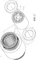
- FIG. 1 is a perspective view of an electric motor according to one embodiment of the disclosure
- FIG. 2 is an exploded view of the electric motor in FIG. 1 .
- This embodiment provides a rotor mechanism 1a which is adapted to an electric motor 9.
- the electric motor 9 includes a stator 2 and two end rings 3.
- the rotor mechanism 1a is rotatably located in the stator 2.
- the two end rings 3 are respectively disposed at two opposite end surfaces of the rotor mechanism 1a.
- the disclosure is not limited to the stator 2 and the end rings 3 and their configurations.
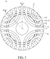
- FIG. 3 is a front view of the electric motor in FIG. 1 .
- the rotor mechanism 1a includes a rotor core 40 and a plurality of rotor bars 50.
- the rotor core 40 has a plurality of rotor slots 41, a plurality of flux barrier groups 42 and a plurality of annular magnetic flux channels 43.
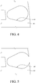
- the rotor slots 41 are arranged along an edge of the rotor core 40. In this embodiment, the rotor slots 41 are spaced apart from an annular outer wall (not numbered) of the rotor core 40. As shown in FIG. 4 , it is a partial enlarged view of a rotor core in FIG. 1 , but the present disclosure is not limited thereto. For example, as shown in FIG. 5 , it is a partial enlarged view of a rotor core according to another embodiment of the disclosure, showing a rotor slot 41' connected to an annular outer wall of a rotor core 40'. In addition, in the embodiment of FIG. 1 , the rotor slot 41 has a cross section in pear shape, but the present disclosure is not limited thereto. For example, in some other embodiments, the cross section of the rotor slot 41 may be in circle, oval or other geometry shapes.
- the rotor bars 50 are respectively inserted into the rotor slots 41.
- the flux barrier groups 42 surround an axis L of the rotor core 40.
- the quantity of the flux barrier groups 42 is the same as the quantity of the poles of the rotor core 40; in detail, in this embodiment, the rotor core 40 has four poles, and the quantity of the flux barrier groups 42 is four, and the four flux barrier groups 42 are respectively located in the four poles of the rotor core 40.
- Each flux barrier group 42 includes a plurality of flux barrier units 420.
- the flux barrier unit 420 extends from one of the rotor slots 41 to another rotor slot 41; that is, the flux barrier unit 420 extends from one of the rotor bars 50 to another rotor bar 50.
- the flux barrier units 420 are spaced apart from the rotor slots 41; that is, the flux barrier units 420 are not directly connected to the rotor slots 41.
- the quantity of the poles of the rotor core 40 that is, the quantity of the flux barrier groups 42
- the quantity of the flux barrier units 420 in each flux barrier group 42 are not restricted, they all can be adjusted according to actual requirements.
- each flux barrier group 42 the flux barrier units 420 are spaced apart at a fixed distance and arranged along a radial direction of the rotor core 40. Furthermore, in this embodiment, in each pole of the rotor core 40 (in each flux barrier group 42), there are three flux barrier units 420 arranged along the radial direction of the rotor core 40. However, the distance between the adjacent flux barrier units 420 is not restricted. For example, in some other embodiments, the flux barrier units in each flux barrier group are arranged along the flux radial direction but may be spaced apart at difference distance.
- FIG. 6 is a partial enlarged view of the rotor core in FIG. 1 .
- the total length of the flux barrier units 420 in a symmetric line of the flux barrier group 42 i.e. a line paralleling to the radial direction of the rotor core 40
- A i.e. a1+a2+a3
- T the thickness of the rotor core 40 in the said line, excluding the hollow portion at the axis L
- the total length A and the thickness T are satisfied with the following condition: 1.4 ⁇ t / a ⁇ 2.5.
- each flux barrier unit 420 has a central portion 421 having a width w1, and also has an end portion 422 having a width w2, and the following condition is satisfied: 0.3 ⁇ w 1 ⁇ w 2.
- the annular magnetic flux channels 43 penetrate through the flux barrier units 420, so that some of the flux barrier units 420 are divided into a plurality of sub-units (not numbered).
- the annular magnetic flux channels 43 surround the axis L of the rotor core 40, and the annular magnetic flux channels 43 in this embodiment are concentric circles; that is, the annular magnetic flux channels 43 share the same center (i.e. the axis L) but every circle has different radius.
- the quantity of the annular magnetic flux channels 43 is not restricted, and it can be adjusted according to actual requirements.
- the rotor core may only have one annular magnetic flux channel 43.
- the shape of the annular magnetic flux channel is not restricted to circle.
- the shape of the annular magnetic flux channel may be oval or other geometric shapes. It is noted that, any annular magnetic flux channel, that penetrates the flux barrier units and surrounds the axis of the rotor core, falls within the scope of the present disclosure.
- each flux barrier unit 420 (including the sub-units) is a barrier for magnetic flux; that is, each sub-unit is a barrier for magnetic flux, but the annular magnetic flux channels 43 and the gap between the adjacent flux barrier units 420 (including the gap between the adjacent sub-units) all can serve as channel for magnetic flux.
- electricity is fed into the electric motor so as to generate excitation current in the rotor bars 50 that respond to the stator windings, such that the rotor core 40 is magnetized to form a closed-loop of magnetic flux line.
- magnetic flux density (B) is the number of magnetic flux lines per unit cross sectional area of magnetic material.
- the arrangement of the annular magnetic flux channels 43 can serve as channels for magnetic flux when the electric motor is in asynchronous mode so as to increase torque, and also can control the magnetic flux in specific directions.
- FIG. 7A shows magnetic flux line in the electric motor in FIG. 1 when it is in synchronous mode
- FIG. 7B shows magnetic flux line in the electric motor in FIG. 1 when it is in asynchronous mode.
- FIG. 7A shows that the electric motor is in the synchronous mode, due to the arrangement of the flux barrier units 420 on the rotor core 40, magnetic flux is controlled in specific directions. At this moment, the magnetic flux is mostly limited to the gap between the adjacent flux barrier units 420. When it requires larger synchronous torque output, most of the magnetic flux goes along d-axis.
- FIG. 7B shows that the electric motor is in the asynchronous mode, when it requires larger asynchronous torque characteristics, due to the arrangement of the flux barrier units 420 on the rotor core 40, the magnetic flux is allowed to pass through the annular magnetic flux channels 43, and the magnetic flux is not limited to the area between the rotor bars 50 and the flux barrier units 420. Also, when the magnetic flux passes through the annular magnetic flux channels 43, the high magnetic material of the rotor core 40 can transport magnetic flux without oversaturation and has no hysteresis loss and eddy current loss, and the electric motor does not have a sharp increase in temperature, whereby increasing torque while operating in asynchronous mode.
- the arrangements of the annular magnetic flux channels 43 and the flux barrier units 420 help to gather the magnetic flux so as to adjust its density to an ideal value, for example, approximately 1.2 Tesla to 2.0 Tesla.
- an inductance of d-axis (Ld) is approximately 1 to 5 times an inductance of q-axis (Lq) so as to create an inductance difference (Ld-Lq).
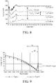
- FIG. 8 shows the inductance differences of two types of electric motors-type a and type b, wherein the type b is the electric motor in FIG. 1 , and the type a is an electric motor without the annular magnetic flux channels.
- the inductance difference (Ld-Lq) between d-axis and q-axis is approximately 43mH, and the Ld is approximately 1.4 times the Lq.
- the inductance difference (Ld-Lq) between the d-axis and q-axis is approximately 154mH.
- the increase of the inductance difference (Ld-Lq) between the d-axis and q-axis will directly affect the amount of torque output and also will change the torque characteristics and efficiency of the electric motor.
- FIG. 9 compares switch torque of the electric motor in FIG. 1 with that of an electric motor without the annular magnetic flux channel. It can be seen that, the more the amount of the sub-units of the flux barrier units 420 (that is, the rotor mechanism with the annular magnetic flux channels 43 penetrating through the flux barrier units 420), the great the torque in asynchronous operation and the less the torque in synchronous operation. In contrast, in the rotor mechanism without the annular magnetic flux channels 43, the torque in asynchronous operation is smaller, and the torque in synchronous operation is increased.
- FIG. 9 shows switching torque between the synchronous and asynchronous operations.
- the difference in structure causes the speed differences between the synchronous and asynchronous operations. It can be seen that the rotor mechanism with the annular magnetic flux channels 43 penetrating through the flux barrier units 420; that is, the great amount of the sub-units of the flux barrier units 420, the less a speed difference S2. In contrast, in the rotor mechanism without the annular magnetic flux channels 43, it has a greater speed difference S1.
- FIG. 10 is a graph showing efficiency of the electric motor in FIG. 1 .
- the electric motor can provide an ultra-premium efficiency and synchronous operation characteristic.
- the following is a temperature comparison table of the electric motor of the disclosure and a conventional electric motor.
- the table shows that both the electric motor operates in a condition of 1.5kW/60Hz/220V, and it can be seen that the increase of temperature of the electric motor of the disclosure is relatively lower than that of the conventional electric motor.
- the arrangements of the flux barrier units 420 and the annular magnetic flux channels 43 at least can provide the following advantages:
- the rotor mechanism of the present disclosure is able to provide an ultra-premium efficiency in energy conversion, a self-start characteristic, an ability to operate in synchronous mode, an ability to operate in a wide range of power, an adjustment of torque, and an effect of moderately switching asynchronous and synchronous modes.
Landscapes
- Engineering & Computer Science (AREA)
- Power Engineering (AREA)
- Iron Core Of Rotating Electric Machines (AREA)
- Synchronous Machinery (AREA)
- Permanent Field Magnets Of Synchronous Machinery (AREA)
Abstract
Description
- The disclosure relates to a rotor mechanism, more particularly to a rotor mechanism having annular magnetic flux channel.
- Electric motors can convert electrical energy into mechanical energy through electromagnetic interactions. The electric motors are widely used in daily life and applied to many fields. For example, the electric motors can be applied to machine tools, water pumps, light machineries, wind power systems, hydroelectric power generation systems and the like. The electric motors are fundamental machines in industry and closely linked with economic development.
- Regarding to energy saving issues, International Electrotechnical Commission (IEC) provides the energy efficiency standards for electric motors, for example, IE1 to IE4, even to IE5, from low to high. In order to achieve the high efficiency standards, induction electric motors mostly use high magnetically conductive materials or high level magnetically conductive steels, but the increase of efficiency has hit the bottleneck. As a result, some manufactures stop develop the induction electric motors, they start to put rare earth materials and actuator into an electric motor in order to achieve level IE5, but the overall cost is largely increased. In addition, the rare earth materials have potential problems of demagnetization, and such electric motors cannot be directly connected to electric supply. Thus, the developers are constantly trying to develop a high efficiency and cost effective electric motor.
- The present disclosure provides a rotor mechanism having both advantages of synchronous and asynchronous electric motors and capable of providing high efficiency.
- One embodiment of the disclosure provides a rotor mechanism including a plurality of rotor bars and a rotor core. The plurality of rotor bars are arranged along an edge of the rotor core, the rotor core has a plurality of flux barrier units and at least one annular magnetic flux channel. The plurality of flux barrier units respectively extend from one of the plurality of rotor bars to another one of the plurality of rotor bars, and the at least one annular magnetic flux channel penetrate through the plurality of flux barrier units and surround an axis of the rotor core. Each of the plurality of flux barrier units is a barrier for magnetic flux, and the at least one annular magnetic flux channel and a gap between the adjacent flux barrier units are channels for magnetic flux.
- According to the rotor mechanism as discussed above, the arrangement of the flux barrier units and the annular magnetic flux channel is able to provide channels for magnetic flux when an electric motor having the rotor mechanism operates in asynchronous mode so as to increase torque, and is also able to control the magnetic flux in specific directions when the electric motor operates in synchronous mode, such that the rotor mechanism allows the electric motor to have both advantages of synchronous and asynchronous motors, thereby making the electric motor to provide ultra-premium efficiency.
- The above description of the disclosure and the following description of embodiments of the disclosure are provided to exemplify and explain the spirit and principle of the disclosure and provide a further explanation of the scope of the disclosure.
- The present disclosure will become better understood from the detailed description given hereinbelow and the accompanying drawings which are given by way of illustration only and thus are not intending to limit the present disclosure and wherein:
-
FIG. 1 is a perspective view of an electric motor according to one embodiment of the disclosure. -
FIG. 2 is an exploded view of the electric motor inFIG. 1 . -
FIG. 3 is a front view of the electric motor inFIG. 1 . -
FIG. 4 is a partial enlarged view of a rotor core inFIG. 1 . -
FIG. 5 is a partial enlarged view of a rotor core according to another embodiment of the disclosure. -
FIG. 6 is a partial enlarged view of the rotor core inFIG. 1 . -
FIG. 7A shows magnetic flux line in the electric motor inFIG. 1 when it is in synchronous mode. -
FIG. 7B shows magnetic flux line in the electric motor inFIG. 1 when it is in asynchronous mode. -
FIG. 8 shows inductance differences of the electric motor inFIG. 1 and another electric motor without annular magnetic flux channels. -
FIG. 9 shows comparison of switch torque of the electric motor inFIG. 1 and that of the electric motor without the annular magnetic flux channels. -
FIG. 10 is a graph showing efficiency of the electric motor inFIG. 1 . - In the following detailed description, for purposes of explanation, numerous specific details are set forth in order to provide a thorough understanding of the disclosed embodiments. It will be apparent, however, that one or more embodiments may be practiced without these specific details. In other instances, well-known main structures and devices are schematically shown in order to simplify the drawing.
- In addition, the terms used in the present disclosure, such as technical and scientific terms, have its own meanings and can be comprehended by those skilled in the art, unless the terms are additionally defined in the present disclosure. That is, the terms used in the following paragraphs should be read on the meaning commonly used in the related fields and will not be overly explained, unless the terms have a specific meaning in the present disclosure. Furthermore, in order to simplify the drawings, some conventional structures and components are drawn in a simplified manner to keep the drawings clean.
- Furthermore, unless being specifically defined, all terms used herein, including technical and scientific terms, have their common meanings, as those whose meanings can be understood by those skilled in the art. Further, the definition of the above terms should be interpreted in the present specification as having the same meaning as the technical field related to the present disclosure. Unless specifically defined, these terms are not to be interpreted as being too idealistic or formal.
- Please refer to
FIGS. 1-2 ,FIG. 1 is a perspective view of an electric motor according to one embodiment of the disclosure, andFIG. 2 is an exploded view of the electric motor inFIG. 1 . - This embodiment provides a rotor mechanism 1a which is adapted to an
electric motor 9. Theelectric motor 9 includes astator 2 and two end rings 3. The rotor mechanism 1a is rotatably located in thestator 2. The two end rings 3 are respectively disposed at two opposite end surfaces of the rotor mechanism 1a. However, the disclosure is not limited to thestator 2 and the end rings 3 and their configurations. - Then, the rotor mechanism 1a will be described in more detail in the following paragraphs. Please further refer to
FIG. 3, FIG. 3 is a front view of the electric motor inFIG. 1 . The rotor mechanism 1a includes arotor core 40 and a plurality ofrotor bars 50. Therotor core 40 has a plurality ofrotor slots 41, a plurality offlux barrier groups 42 and a plurality of annularmagnetic flux channels 43. - The
rotor slots 41 are arranged along an edge of therotor core 40. In this embodiment, therotor slots 41 are spaced apart from an annular outer wall (not numbered) of therotor core 40. As shown inFIG. 4 , it is a partial enlarged view of a rotor core inFIG. 1 , but the present disclosure is not limited thereto. For example, as shown inFIG. 5 , it is a partial enlarged view of a rotor core according to another embodiment of the disclosure, showing a rotor slot 41' connected to an annular outer wall of a rotor core 40'. In addition, in the embodiment ofFIG. 1 , therotor slot 41 has a cross section in pear shape, but the present disclosure is not limited thereto. For example, in some other embodiments, the cross section of therotor slot 41 may be in circle, oval or other geometry shapes. - Please refer back to
FIG. 3 , therotor bars 50 are respectively inserted into therotor slots 41. - The
flux barrier groups 42 surround an axis L of therotor core 40. In this embodiment, the quantity of theflux barrier groups 42 is the same as the quantity of the poles of therotor core 40; in detail, in this embodiment, therotor core 40 has four poles, and the quantity of theflux barrier groups 42 is four, and the fourflux barrier groups 42 are respectively located in the four poles of therotor core 40. - Each
flux barrier group 42 includes a plurality offlux barrier units 420. Theflux barrier unit 420 extends from one of therotor slots 41 to anotherrotor slot 41; that is, theflux barrier unit 420 extends from one of the rotor bars 50 to anotherrotor bar 50. In addition, in this or some other embodiments, there is no magnetic in theflux barrier unit 420. Furthermore, in this embodiment, theflux barrier units 420 are spaced apart from therotor slots 41; that is, theflux barrier units 420 are not directly connected to therotor slots 41. Moreover, the quantity of the poles of the rotor core 40 (that is, the quantity of the flux barrier groups 42) and the quantity of theflux barrier units 420 in eachflux barrier group 42 are not restricted, they all can be adjusted according to actual requirements. - In this embodiment, in each
flux barrier group 42, theflux barrier units 420 are spaced apart at a fixed distance and arranged along a radial direction of therotor core 40. Furthermore, in this embodiment, in each pole of the rotor core 40 (in each flux barrier group 42), there are threeflux barrier units 420 arranged along the radial direction of therotor core 40. However, the distance between the adjacentflux barrier units 420 is not restricted. For example, in some other embodiments, the flux barrier units in each flux barrier group are arranged along the flux radial direction but may be spaced apart at difference distance. - Furthermore, please refer to
FIG. 6, FIG. 6 is a partial enlarged view of the rotor core inFIG. 1 . In eachflux barrier group 42, the total length of theflux barrier units 420 in a symmetric line of the flux barrier group 42 (i.e. a line paralleling to the radial direction of the rotor core 40) equals to A (i.e. a1+a2+a3), and the thickness of therotor core 40 in the said line, excluding the hollow portion at the axis L, equals to T. - The total length A and the thickness T are satisfied with the following condition:
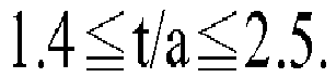
- In addition, each
flux barrier unit 420 has acentral portion 421 having a width w1, and also has anend portion 422 having a width w2, and the following condition is satisfied:
- It is noted that, in this embodiment, the annular
magnetic flux channels 43 penetrate through theflux barrier units 420, so that some of theflux barrier units 420 are divided into a plurality of sub-units (not numbered). In detail, the annularmagnetic flux channels 43 surround the axis L of therotor core 40, and the annularmagnetic flux channels 43 in this embodiment are concentric circles; that is, the annularmagnetic flux channels 43 share the same center (i.e. the axis L) but every circle has different radius. However, the quantity of the annularmagnetic flux channels 43 is not restricted, and it can be adjusted according to actual requirements. For example, in some other embodiments, the rotor core may only have one annularmagnetic flux channel 43. In addition, the shape of the annular magnetic flux channel is not restricted to circle. For example, in some other embodiments, the shape of the annular magnetic flux channel may be oval or other geometric shapes. It is noted that, any annular magnetic flux channel, that penetrates the flux barrier units and surrounds the axis of the rotor core, falls within the scope of the present disclosure. - To the
rotor core 40, each flux barrier unit 420 (including the sub-units) is a barrier for magnetic flux; that is, each sub-unit is a barrier for magnetic flux, but the annularmagnetic flux channels 43 and the gap between the adjacent flux barrier units 420 (including the gap between the adjacent sub-units) all can serve as channel for magnetic flux. In operation, electricity is fed into the electric motor so as to generate excitation current in the rotor bars 50 that respond to the stator windings, such that therotor core 40 is magnetized to form a closed-loop of magnetic flux line. At this moment, magnetic flux density (B) is the number of magnetic flux lines per unit cross sectional area of magnetic material. The arrangement of the annularmagnetic flux channels 43 can serve as channels for magnetic flux when the electric motor is in asynchronous mode so as to increase torque, and also can control the magnetic flux in specific directions. - For example, please refer to
FIGS. 7A-7B, FIG. 7A shows magnetic flux line in the electric motor inFIG. 1 when it is in synchronous mode, andFIG. 7B shows magnetic flux line in the electric motor inFIG. 1 when it is in asynchronous mode. -
FIG. 7A shows that the electric motor is in the synchronous mode, due to the arrangement of theflux barrier units 420 on therotor core 40, magnetic flux is controlled in specific directions. At this moment, the magnetic flux is mostly limited to the gap between the adjacentflux barrier units 420. When it requires larger synchronous torque output, most of the magnetic flux goes along d-axis. - Then,
FIG. 7B shows that the electric motor is in the asynchronous mode, when it requires larger asynchronous torque characteristics, due to the arrangement of theflux barrier units 420 on therotor core 40, the magnetic flux is allowed to pass through the annularmagnetic flux channels 43, and the magnetic flux is not limited to the area between the rotor bars 50 and theflux barrier units 420. Also, when the magnetic flux passes through the annularmagnetic flux channels 43, the high magnetic material of therotor core 40 can transport magnetic flux without oversaturation and has no hysteresis loss and eddy current loss, and the electric motor does not have a sharp increase in temperature, whereby increasing torque while operating in asynchronous mode. - In addition, according to a result of experiment, the arrangements of the annular
magnetic flux channels 43 and theflux barrier units 420 help to gather the magnetic flux so as to adjust its density to an ideal value, for example, approximately 1.2 Tesla to 2.0 Tesla. - The quantities of the
flux barrier units 420 and the annularmagnetic flux channels 43 are not restricted, in an exemplary embodiment of the disclosure, by adjusting the quantities of theflux barrier units 420 and the annularmagnetic flux channels 43, an inductance of d-axis (Ld) is approximately 1 to 5 times an inductance of q-axis (Lq) so as to create an inductance difference (Ld-Lq). For example,FIG. 8 shows the inductance differences of two types of electric motors-type a and type b, wherein the type b is the electric motor inFIG. 1 , and the type a is an electric motor without the annular magnetic flux channels. In detail,FIG. 8 shows the comparison of the inductance difference (Ld-Lq) between the electric motor with the annularmagnetic flux channels 43 and another electric motor without the annularmagnetic flux channels 43; it is noted that the only difference between these two electric motors is that one of them has the annularmagnetic flux channels 43. - In more detail, in the aforementioned rotor mechanism 1a which has the annular
magnetic flux channels 43, after it operates for a predetermined period of time, the inductance difference (Ld-Lq) between d-axis and q-axis is approximately 43mH, and the Ld is approximately 1.4 times the Lq. In contrast, in the electric motor without the annularmagnetic flux channels 43, the inductance difference (Ld-Lq) between the d-axis and q-axis is approximately 154mH. The increase of the inductance difference (Ld-Lq) between the d-axis and q-axis will directly affect the amount of torque output and also will change the torque characteristics and efficiency of the electric motor. - Then, please refer to
FIG. 9 , which compares switch torque of the electric motor inFIG. 1 with that of an electric motor without the annular magnetic flux channel. It can be seen that, the more the amount of the sub-units of the flux barrier units 420 (that is, the rotor mechanism with the annularmagnetic flux channels 43 penetrating through the flux barrier units 420), the great the torque in asynchronous operation and the less the torque in synchronous operation. In contrast, in the rotor mechanism without the annularmagnetic flux channels 43, the torque in asynchronous operation is smaller, and the torque in synchronous operation is increased.FIG. 9 shows switching torque between the synchronous and asynchronous operations. - Also, the difference in structure causes the speed differences between the synchronous and asynchronous operations. It can be seen that the rotor mechanism with the annular
magnetic flux channels 43 penetrating through theflux barrier units 420; that is, the great amount of the sub-units of theflux barrier units 420, the less a speed difference S2. In contrast, in the rotor mechanism without the annularmagnetic flux channels 43, it has a greater speed difference S1. - Then, please refer to
FIG. 10 , is a graph showing efficiency of the electric motor inFIG. 1 . As shown inFIG. 10 , among a wide range of power, the electric motor can provide an ultra-premium efficiency and synchronous operation characteristic. - Finally, the following is a temperature comparison table of the electric motor of the disclosure and a conventional electric motor. The table shows that both the electric motor operates in a condition of 1.5kW/60Hz/220V, and it can be seen that the increase of temperature of the electric motor of the disclosure is relatively lower than that of the conventional electric motor.
Electric motor of the disclosure Conventional electric motor environment temperature 20.1°C 22.6°C Windings temperature 41.5°C 78.8°C the increase of temperature ΔT=21.4°C ΔT=56.2°C - As discussed in above, the arrangements of the
flux barrier units 420 and the annularmagnetic flux channels 43 at least can provide the following advantages: - (a) making the electric motor having the electric mechanism of the disclosure become a duo-mode electric motor capable of operating in synchronous mode and asynchronous mode;
- (b) allowing the electric motor to provide ultra-premium efficiency when in synchronous mode;
- (c) obtaining higher switch torque;
- (d) making the
switch torque 1 to 5 times than the torque output required by the rated power; - (e) obtaining higher energy conversion efficiency, for example, the electric motor in
FIG. 1 is evaluated having an efficiency of 94% and at level IE5 by Taiwan Accreditation Foundation (TAF); and - (f) dividing the flux barrier units into the sub-units by the annular magnetic flux channels, which helps to reduce the variation from switch torque to the torque in asynchronous mode.
- It is understood that the rotor mechanism of the present disclosure is able to provide an ultra-premium efficiency in energy conversion, a self-start characteristic, an ability to operate in synchronous mode, an ability to operate in a wide range of power, an adjustment of torque, and an effect of moderately switching asynchronous and synchronous modes.
- Although the present disclosure is disclosed by the foregoing embodiments, it is not intended to limit the scope of the present disclosure. Changes and modifications without departing from the spirit and scope of the present disclosure all fall within the protection scope of the present disclosure. For the protection scope defined by the present disclosure, please refer to the appended patent claims.
Claims (10)
- A rotor mechanism (1a), comprising:a plurality of rotor bars (50); anda rotor core (40), the plurality of rotor bars being arranged along an edge of the rotor core, the rotor core having a plurality of flux barrier units (420) and at least one annular magnetic flux channel (43), the plurality of flux barrier units respectively extending from one of the plurality of rotor bars to another one of the plurality of rotor bars, and the at least one annular magnetic flux channel penetrating through the plurality of flux barrier units and surrounding an axis (L) of the rotor core, wherein, each of the plurality of flux barrier units is a barrier for magnetic flux, and the at least one annular magnetic flux channel and a gap between the adjacent flux barrier units are channels for magnetic flux.
- The rotor mechanism according to claim 1, wherein the quantity of the at least one annular magnetic flux channel is plural, and the annular magnetic flux channels are concentric circles.
- The rotor mechanism according to claim 1, wherein the plurality of flux barrier units form a plurality of flux barrier groups (42), the plurality of flux barrier groups surround the axis of the rotor core, and the flux barrier units in each of the plurality of flux barrier groups are arranged in a radial direction of the rotor core.
- The rotor mechanism according to claim 3, wherein the flux barrier units in each of the plurality of flux barrier groups are spaced apart at a fixed distance in a radial direction of the rotor core.
- The rotor mechanism according to claim 3, wherein the flux barrier units in each of the plurality of flux barrier groups are spaced apart at different distances in a radial direction of the rotor core.
- The rotor mechanism according to claim 3, wherein a total length of the flux barrier units in each of the plurality of flux barrier groups in a radial direction of the rotor core is A, and a thickness of the rotor core in the radial direction is T, the following condition is satisfied:

- The rotor mechanism according to claim 1, wherein each of the flux barrier units has a central portion having a width which is w1 and an end portion having a width which is w2, the following condition is satisfied:

- The rotor mechanism according to claim 1, wherein the rotor core further has a plurality of rotor slots (41) for the plurality of rotor bars.
- The rotor mechanism according to claim 8, wherein each of the plurality of rotor slots is connected to an annular outer wall of the rotor core.
- The rotor mechanism according to claim 8, wherein each of the plurality of rotor slots is spaced apart from an annular outer wall of the rotor core.
Applications Claiming Priority (2)
| Application Number | Priority Date | Filing Date | Title |
|---|---|---|---|
| US201762517075P | 2017-06-08 | 2017-06-08 | |
| TW106144507A TWI649940B (en) | 2017-06-08 | 2017-12-19 | Rotor mechanism |
Publications (2)
| Publication Number | Publication Date |
|---|---|
| EP3413439A1 true EP3413439A1 (en) | 2018-12-12 |
| EP3413439B1 EP3413439B1 (en) | 2023-04-26 |
Family
ID=61283046
Family Applications (1)
| Application Number | Title | Priority Date | Filing Date |
|---|---|---|---|
| EP18158531.6A Active EP3413439B1 (en) | 2017-06-08 | 2018-02-26 | Rotor |
Country Status (3)
| Country | Link |
|---|---|
| US (1) | US10742080B2 (en) |
| EP (1) | EP3413439B1 (en) |
| CN (1) | CN109038883B (en) |
Cited By (3)
| Publication number | Priority date | Publication date | Assignee | Title |
|---|---|---|---|---|
| CN110224565A (en) * | 2019-06-19 | 2019-09-10 | 珠海格力电器股份有限公司 | Synchronous reluctance motor rotor structure, motor and compressor |
| KR20220073450A (en) * | 2020-11-26 | 2022-06-03 | 한양대학교 산학협력단 | Rotor of line start synchronous reluctance motor with improved stiffness and power |
| DE102022001424A1 (en) | 2021-05-19 | 2022-11-24 | Sew-Eurodrive Gmbh & Co Kg | Electric motor with rotor shaft and laminated core |
Families Citing this family (7)
| Publication number | Priority date | Publication date | Assignee | Title |
|---|---|---|---|---|
| KR102872739B1 (en) * | 2018-08-07 | 2025-10-16 | 타우 모터스, 인크. | Electric motors |
| CN110149015B (en) * | 2019-06-19 | 2025-05-16 | 珠海格力电器股份有限公司 | Direct start synchronous reluctance motor rotor structure, motor |
| CN110474507A (en) * | 2019-07-25 | 2019-11-19 | 江苏大学 | A kind of multi-state leakage field controllable type wide range speed control high efficiency permanent magnetic brushless |
| CN111245195B (en) * | 2020-03-03 | 2021-11-02 | 东南大学 | A Squirrel-Cage Conductor Rotor Brushless Power Feedback Permanent Magnet Governor |
| IT202000006052A1 (en) * | 2020-03-23 | 2021-09-23 | Motovario S P A | SELF-STARTING RELUCTANCE MOTOR. |
| JP7478694B2 (en) * | 2021-03-08 | 2024-05-07 | 株式会社日立製作所 | Rotating magnetic field generator, magnetic refrigeration device, and hydrogen liquefaction device |
| WO2023164884A1 (en) * | 2022-03-03 | 2023-09-07 | 罗灿 | Synchronous reluctance tangential induction coil rotor |
Citations (3)
| Publication number | Priority date | Publication date | Assignee | Title |
|---|---|---|---|---|
| GB940997A (en) * | 1959-12-08 | 1963-11-06 | Allis Louis Co | Improvements in or relating to electric motors |
| GB1270807A (en) * | 1968-06-13 | 1972-04-19 | Nat Res Dev | Reluctance motors |
| US20150372577A1 (en) * | 2013-02-01 | 2015-12-24 | Ksb Aktiengesellschaft | Rotor, Reluctance Machine and Production Method for a Rotor |
Family Cites Families (25)
| Publication number | Priority date | Publication date | Assignee | Title |
|---|---|---|---|---|
| US2913607A (en) | 1957-01-16 | 1959-11-17 | Allis Louis Co | Synchronous induction motor |
| US3721844A (en) | 1971-05-27 | 1973-03-20 | Nat Res Dev | Reluctance motors |
| US5831367A (en) * | 1997-02-13 | 1998-11-03 | Emerson Electric Co. | Line-start reluctance motor with grain-oriented rotor laminations |
| ITTO20010182A1 (en) * | 2001-03-02 | 2002-09-02 | Fiat Ricerche | SYNCHRONOUS TYPE ELECTRIC MACHINE. |
| KR100565830B1 (en) | 2002-12-12 | 2006-03-30 | 엘지전자 주식회사 | Rotor for line-start reluctance motor |
| US20070152527A1 (en) * | 2005-12-23 | 2007-07-05 | Okuma Corporation | Reluctance motor |
| US20080145252A1 (en) * | 2006-12-15 | 2008-06-19 | Lg Electronics Inc. | Rotary compressor and air conditioner having the same |
| KR100900290B1 (en) * | 2007-03-09 | 2009-05-29 | 엘지전자 주식회사 | motor |
| EP2237399B1 (en) | 2008-01-25 | 2017-09-27 | Mitsubishi Electric Corporation | Induction electric motor and hermetic compressor |
| JP2009194945A (en) * | 2008-02-12 | 2009-08-27 | Denso Corp | Synchronous reluctance motor |
| CN201438651U (en) | 2009-07-17 | 2010-04-14 | 中国矿业大学 | Rotor structure of a permanent magnet synchronous motor |
| KR101396655B1 (en) * | 2010-06-30 | 2014-05-19 | 에이비비 리써치 리미티드 | Synchronous reluctance machine using rotor flux barriers as cooling channels |
| CN103208894B (en) | 2012-01-11 | 2015-07-29 | 珠海格力电器股份有限公司 | self-starting synchronous reluctance motor and rotor thereof |
| US9490673B2 (en) * | 2012-08-16 | 2016-11-08 | Mitsuba Corporation | Rotor of magnet-assisted reluctance motor and brushless motor |
| US9941775B2 (en) * | 2012-11-01 | 2018-04-10 | General Electric Company | D-ring implementation in skewed rotor assembly |
| JP6147661B2 (en) | 2013-12-27 | 2017-06-14 | 日立オートモティブシステムズ株式会社 | Rotor, permanent magnet type rotating electric machine including the same, electric drive system, electric vehicle |
| DE112014006430B4 (en) * | 2014-03-05 | 2024-05-29 | Mitsubishi Electric Corporation | Synchronous reluctance motor |
| DE102014215303A1 (en) * | 2014-08-04 | 2016-02-04 | Ksb Aktiengesellschaft | Rotor and reluctance machine |
| DE102014215304A1 (en) * | 2014-08-04 | 2016-02-04 | Ksb Aktiengesellschaft | Rotor, reluctance machine and rotor manufacturing method |
| ITUB20150608A1 (en) * | 2015-04-14 | 2016-10-14 | Ge Avio Srl | METHOD OF REALIZATION OF A ROTOR STRUCTURE OF A SYNCHRONOUS RELUCTANCE ELECTRIC MACHINE, AND RELATED RELUCTANCE SYNCHRONOUS ELECTRICAL MACHINE |
| TWM514695U (en) | 2015-04-24 | 2015-12-21 | Visionary Dynamics | Rotor yoke iron |
| JP2017079530A (en) * | 2015-10-20 | 2017-04-27 | 株式会社ジェイテクト | Synchronous reluctance motor |
| CN205544660U (en) | 2016-01-26 | 2016-08-31 | 珠海格力节能环保制冷技术研究中心有限公司 | Synchronous reluctance machine rotor and synchronous reluctance machine |
| EP3261220B1 (en) * | 2016-06-23 | 2020-08-12 | Volvo Car Corporation | Electric machine |
| CN108736601B (en) * | 2017-04-17 | 2020-10-27 | 日本电产株式会社 | Rotor, motor having the same, and method for reducing torque chain wave of rotor |
-
2017
- 2017-12-19 US US15/847,817 patent/US10742080B2/en active Active
- 2017-12-29 CN CN201711471786.5A patent/CN109038883B/en active Active
-
2018
- 2018-02-26 EP EP18158531.6A patent/EP3413439B1/en active Active
Patent Citations (3)
| Publication number | Priority date | Publication date | Assignee | Title |
|---|---|---|---|---|
| GB940997A (en) * | 1959-12-08 | 1963-11-06 | Allis Louis Co | Improvements in or relating to electric motors |
| GB1270807A (en) * | 1968-06-13 | 1972-04-19 | Nat Res Dev | Reluctance motors |
| US20150372577A1 (en) * | 2013-02-01 | 2015-12-24 | Ksb Aktiengesellschaft | Rotor, Reluctance Machine and Production Method for a Rotor |
Cited By (4)
| Publication number | Priority date | Publication date | Assignee | Title |
|---|---|---|---|---|
| CN110224565A (en) * | 2019-06-19 | 2019-09-10 | 珠海格力电器股份有限公司 | Synchronous reluctance motor rotor structure, motor and compressor |
| KR20220073450A (en) * | 2020-11-26 | 2022-06-03 | 한양대학교 산학협력단 | Rotor of line start synchronous reluctance motor with improved stiffness and power |
| DE102022001424A1 (en) | 2021-05-19 | 2022-11-24 | Sew-Eurodrive Gmbh & Co Kg | Electric motor with rotor shaft and laminated core |
| WO2022242901A1 (en) | 2021-05-19 | 2022-11-24 | Sew-Eurodrive Gmbh & Co. Kg | Electric motor having rotor shaft and laminated core |
Also Published As
| Publication number | Publication date |
|---|---|
| CN109038883B (en) | 2020-07-17 |
| EP3413439B1 (en) | 2023-04-26 |
| CN109038883A (en) | 2018-12-18 |
| US10742080B2 (en) | 2020-08-11 |
| US20180358850A1 (en) | 2018-12-13 |
Similar Documents
| Publication | Publication Date | Title |
|---|---|---|
| EP3413439B1 (en) | Rotor | |
| Soderlund et al. | A permanent-magnet generator for wind power applications | |
| Zhou et al. | Comparison of low-cost single-phase wound-field switched-flux machines | |
| CN105207436B (en) | A kind of ring-shaped yoke portion armature winding high power density composite excitation permanent magnet motor | |
| CN105703583B (en) | A kind of multiple stators mixed magnetic circuit permagnetic synchronous motor and method | |
| CN106374718A (en) | Magnetic-concentrating-type consequent-pole cursor permanent magnet motor and application thereof | |
| CN108233563B (en) | A multi-phase hybrid excitation synchronous motor | |
| CN105186749B (en) | A kind of ring-shaped yoke portion double winding composite excitation permanent magnet motor | |
| CN113054762B (en) | A magnetized direct drive permanent magnet motor | |
| CN105790470B (en) | A kind of control method of bimorph transducer composite construction rotor footpath axial direction mixed magnetic circuit permagnetic synchronous motor | |
| CN100370680C (en) | Hybrid Excitation Permanent Magnet Synchronous Generator | |
| US12341380B2 (en) | Axial flux motor | |
| CN105141104B (en) | A kind of yoke portion Exciting Windings for Transverse Differential Protection high power density composite excitation permanent magnet linear electric generator | |
| CN205081652U (en) | A High Power Density Hybrid Excitation Permanent Magnet Motor with Ring Yoke Armature Winding | |
| CN205725388U (en) | A multi-stator hybrid magnetic circuit permanent magnet synchronous motor | |
| CN107493004A (en) | A kind of modularization cylindrical permanent linear synchronous motor | |
| CN202424466U (en) | Single-phase magnetic flux switching type variable reluctance motor | |
| CN205081600U (en) | Duplex winding mixed excitation permanent magnet motor of annular yoke portion | |
| CN105207384B (en) | A kind of double winding high power density composite excitation permanent magnet motor | |
| Hu et al. | Design and analysis of a planar flux-switching permanent magnet motor | |
| CN205081598U (en) | Duplex winding high power density mixed excitation permanent magnet motor | |
| CN205081587U (en) | Excitation winding high power density mixed excitation permanent magnet linear generator of yoke portion | |
| Spargo | Synchronous reluctance technology: part I | |
| Arish et al. | Optimization and comparison of new linear permanent magnet vernier machine | |
| Boldea et al. | 10MW, 10rpm, 15Hz directly-driven reluctance synchronous generator system: preliminary design with key FEM validations |
Legal Events
| Date | Code | Title | Description |
|---|---|---|---|
| PUAI | Public reference made under article 153(3) epc to a published international application that has entered the european phase |
Free format text: ORIGINAL CODE: 0009012 |
|
| STAA | Information on the status of an ep patent application or granted ep patent |
Free format text: STATUS: REQUEST FOR EXAMINATION WAS MADE |
|
| 17P | Request for examination filed |
Effective date: 20180226 |
|
| AK | Designated contracting states |
Kind code of ref document: A1 Designated state(s): AL AT BE BG CH CY CZ DE DK EE ES FI FR GB GR HR HU IE IS IT LI LT LU LV MC MK MT NL NO PL PT RO RS SE SI SK SM TR |
|
| AX | Request for extension of the european patent |
Extension state: BA ME |
|
| RBV | Designated contracting states (corrected) |
Designated state(s): AL AT BE BG CH CY CZ DE DK EE ES FI FR GB GR HR HU IE IS IT LI LT LU LV MC MK MT NL NO PL PT RO RS SE SI SK SM TR |
|
| STAA | Information on the status of an ep patent application or granted ep patent |
Free format text: STATUS: EXAMINATION IS IN PROGRESS |
|
| 17Q | First examination report despatched |
Effective date: 20191126 |
|
| RIC1 | Information provided on ipc code assigned before grant |
Ipc: H02K 17/16 20060101ALN20221114BHEP Ipc: H02K 19/10 20060101ALI20221114BHEP Ipc: H02K 1/24 20060101AFI20221114BHEP |
|
| GRAP | Despatch of communication of intention to grant a patent |
Free format text: ORIGINAL CODE: EPIDOSNIGR1 |
|
| STAA | Information on the status of an ep patent application or granted ep patent |
Free format text: STATUS: GRANT OF PATENT IS INTENDED |
|
| INTG | Intention to grant announced |
Effective date: 20230105 |
|
| GRAS | Grant fee paid |
Free format text: ORIGINAL CODE: EPIDOSNIGR3 |
|
| GRAA | (expected) grant |
Free format text: ORIGINAL CODE: 0009210 |
|
| STAA | Information on the status of an ep patent application or granted ep patent |
Free format text: STATUS: THE PATENT HAS BEEN GRANTED |
|
| AK | Designated contracting states |
Kind code of ref document: B1 Designated state(s): AL AT BE BG CH CY CZ DE DK EE ES FI FR GB GR HR HU IE IS IT LI LT LU LV MC MK MT NL NO PL PT RO RS SE SI SK SM TR |
|
| REG | Reference to a national code |
Ref country code: GB Ref legal event code: FG4D |
|
| REG | Reference to a national code |
Ref country code: CH Ref legal event code: EP |
|
| REG | Reference to a national code |
Ref country code: DE Ref legal event code: R096 Ref document number: 602018048805 Country of ref document: DE |
|
| REG | Reference to a national code |
Ref country code: AT Ref legal event code: REF Ref document number: 1563538 Country of ref document: AT Kind code of ref document: T Effective date: 20230515 |
|
| REG | Reference to a national code |
Ref country code: IE Ref legal event code: FG4D |
|
| REG | Reference to a national code |
Ref country code: LT Ref legal event code: MG9D |
|
| REG | Reference to a national code |
Ref country code: NL Ref legal event code: MP Effective date: 20230426 |
|
| REG | Reference to a national code |
Ref country code: AT Ref legal event code: MK05 Ref document number: 1563538 Country of ref document: AT Kind code of ref document: T Effective date: 20230426 |
|
| PG25 | Lapsed in a contracting state [announced via postgrant information from national office to epo] |
Ref country code: NL Free format text: LAPSE BECAUSE OF FAILURE TO SUBMIT A TRANSLATION OF THE DESCRIPTION OR TO PAY THE FEE WITHIN THE PRESCRIBED TIME-LIMIT Effective date: 20230426 |
|
| PG25 | Lapsed in a contracting state [announced via postgrant information from national office to epo] |
Ref country code: SE Free format text: LAPSE BECAUSE OF FAILURE TO SUBMIT A TRANSLATION OF THE DESCRIPTION OR TO PAY THE FEE WITHIN THE PRESCRIBED TIME-LIMIT Effective date: 20230426 Ref country code: PT Free format text: LAPSE BECAUSE OF FAILURE TO SUBMIT A TRANSLATION OF THE DESCRIPTION OR TO PAY THE FEE WITHIN THE PRESCRIBED TIME-LIMIT Effective date: 20230828 Ref country code: NO Free format text: LAPSE BECAUSE OF FAILURE TO SUBMIT A TRANSLATION OF THE DESCRIPTION OR TO PAY THE FEE WITHIN THE PRESCRIBED TIME-LIMIT Effective date: 20230726 Ref country code: ES Free format text: LAPSE BECAUSE OF FAILURE TO SUBMIT A TRANSLATION OF THE DESCRIPTION OR TO PAY THE FEE WITHIN THE PRESCRIBED TIME-LIMIT Effective date: 20230426 Ref country code: AT Free format text: LAPSE BECAUSE OF FAILURE TO SUBMIT A TRANSLATION OF THE DESCRIPTION OR TO PAY THE FEE WITHIN THE PRESCRIBED TIME-LIMIT Effective date: 20230426 |
|
| PG25 | Lapsed in a contracting state [announced via postgrant information from national office to epo] |
Ref country code: RS Free format text: LAPSE BECAUSE OF FAILURE TO SUBMIT A TRANSLATION OF THE DESCRIPTION OR TO PAY THE FEE WITHIN THE PRESCRIBED TIME-LIMIT Effective date: 20230426 Ref country code: PL Free format text: LAPSE BECAUSE OF FAILURE TO SUBMIT A TRANSLATION OF THE DESCRIPTION OR TO PAY THE FEE WITHIN THE PRESCRIBED TIME-LIMIT Effective date: 20230426 Ref country code: LV Free format text: LAPSE BECAUSE OF FAILURE TO SUBMIT A TRANSLATION OF THE DESCRIPTION OR TO PAY THE FEE WITHIN THE PRESCRIBED TIME-LIMIT Effective date: 20230426 Ref country code: LT Free format text: LAPSE BECAUSE OF FAILURE TO SUBMIT A TRANSLATION OF THE DESCRIPTION OR TO PAY THE FEE WITHIN THE PRESCRIBED TIME-LIMIT Effective date: 20230426 Ref country code: IS Free format text: LAPSE BECAUSE OF FAILURE TO SUBMIT A TRANSLATION OF THE DESCRIPTION OR TO PAY THE FEE WITHIN THE PRESCRIBED TIME-LIMIT Effective date: 20230826 Ref country code: HR Free format text: LAPSE BECAUSE OF FAILURE TO SUBMIT A TRANSLATION OF THE DESCRIPTION OR TO PAY THE FEE WITHIN THE PRESCRIBED TIME-LIMIT Effective date: 20230426 Ref country code: GR Free format text: LAPSE BECAUSE OF FAILURE TO SUBMIT A TRANSLATION OF THE DESCRIPTION OR TO PAY THE FEE WITHIN THE PRESCRIBED TIME-LIMIT Effective date: 20230727 |
|
| PG25 | Lapsed in a contracting state [announced via postgrant information from national office to epo] |
Ref country code: FI Free format text: LAPSE BECAUSE OF FAILURE TO SUBMIT A TRANSLATION OF THE DESCRIPTION OR TO PAY THE FEE WITHIN THE PRESCRIBED TIME-LIMIT Effective date: 20230426 |
|
| PG25 | Lapsed in a contracting state [announced via postgrant information from national office to epo] |
Ref country code: SK Free format text: LAPSE BECAUSE OF FAILURE TO SUBMIT A TRANSLATION OF THE DESCRIPTION OR TO PAY THE FEE WITHIN THE PRESCRIBED TIME-LIMIT Effective date: 20230426 |
|
| REG | Reference to a national code |
Ref country code: DE Ref legal event code: R097 Ref document number: 602018048805 Country of ref document: DE |
|
| PG25 | Lapsed in a contracting state [announced via postgrant information from national office to epo] |
Ref country code: SM Free format text: LAPSE BECAUSE OF FAILURE TO SUBMIT A TRANSLATION OF THE DESCRIPTION OR TO PAY THE FEE WITHIN THE PRESCRIBED TIME-LIMIT Effective date: 20230426 Ref country code: SK Free format text: LAPSE BECAUSE OF FAILURE TO SUBMIT A TRANSLATION OF THE DESCRIPTION OR TO PAY THE FEE WITHIN THE PRESCRIBED TIME-LIMIT Effective date: 20230426 Ref country code: RO Free format text: LAPSE BECAUSE OF FAILURE TO SUBMIT A TRANSLATION OF THE DESCRIPTION OR TO PAY THE FEE WITHIN THE PRESCRIBED TIME-LIMIT Effective date: 20230426 Ref country code: EE Free format text: LAPSE BECAUSE OF FAILURE TO SUBMIT A TRANSLATION OF THE DESCRIPTION OR TO PAY THE FEE WITHIN THE PRESCRIBED TIME-LIMIT Effective date: 20230426 Ref country code: DK Free format text: LAPSE BECAUSE OF FAILURE TO SUBMIT A TRANSLATION OF THE DESCRIPTION OR TO PAY THE FEE WITHIN THE PRESCRIBED TIME-LIMIT Effective date: 20230426 |
|
| PLBE | No opposition filed within time limit |
Free format text: ORIGINAL CODE: 0009261 |
|
| STAA | Information on the status of an ep patent application or granted ep patent |
Free format text: STATUS: NO OPPOSITION FILED WITHIN TIME LIMIT |
|
| 26N | No opposition filed |
Effective date: 20240129 |
|
| PG25 | Lapsed in a contracting state [announced via postgrant information from national office to epo] |
Ref country code: SI Free format text: LAPSE BECAUSE OF FAILURE TO SUBMIT A TRANSLATION OF THE DESCRIPTION OR TO PAY THE FEE WITHIN THE PRESCRIBED TIME-LIMIT Effective date: 20230426 |
|
| PG25 | Lapsed in a contracting state [announced via postgrant information from national office to epo] |
Ref country code: SI Free format text: LAPSE BECAUSE OF FAILURE TO SUBMIT A TRANSLATION OF THE DESCRIPTION OR TO PAY THE FEE WITHIN THE PRESCRIBED TIME-LIMIT Effective date: 20230426 |
|
| PG25 | Lapsed in a contracting state [announced via postgrant information from national office to epo] |
Ref country code: MC Free format text: LAPSE BECAUSE OF FAILURE TO SUBMIT A TRANSLATION OF THE DESCRIPTION OR TO PAY THE FEE WITHIN THE PRESCRIBED TIME-LIMIT Effective date: 20230426 |
|
| REG | Reference to a national code |
Ref country code: CH Ref legal event code: PL |
|
| PG25 | Lapsed in a contracting state [announced via postgrant information from national office to epo] |
Ref country code: LU Free format text: LAPSE BECAUSE OF NON-PAYMENT OF DUE FEES Effective date: 20240226 |
|
| PG25 | Lapsed in a contracting state [announced via postgrant information from national office to epo] |
Ref country code: CH Free format text: LAPSE BECAUSE OF NON-PAYMENT OF DUE FEES Effective date: 20240229 |
|
| GBPC | Gb: european patent ceased through non-payment of renewal fee |
Effective date: 20240226 |
|
| PG25 | Lapsed in a contracting state [announced via postgrant information from national office to epo] |
Ref country code: LU Free format text: LAPSE BECAUSE OF NON-PAYMENT OF DUE FEES Effective date: 20240226 Ref country code: CH Free format text: LAPSE BECAUSE OF NON-PAYMENT OF DUE FEES Effective date: 20240229 |
|
| PG25 | Lapsed in a contracting state [announced via postgrant information from national office to epo] |
Ref country code: BG Free format text: LAPSE BECAUSE OF FAILURE TO SUBMIT A TRANSLATION OF THE DESCRIPTION OR TO PAY THE FEE WITHIN THE PRESCRIBED TIME-LIMIT Effective date: 20230426 |
|
| PG25 | Lapsed in a contracting state [announced via postgrant information from national office to epo] |
Ref country code: BG Free format text: LAPSE BECAUSE OF FAILURE TO SUBMIT A TRANSLATION OF THE DESCRIPTION OR TO PAY THE FEE WITHIN THE PRESCRIBED TIME-LIMIT Effective date: 20230426 |
|
| REG | Reference to a national code |
Ref country code: BE Ref legal event code: MM Effective date: 20240229 |
|
| PG25 | Lapsed in a contracting state [announced via postgrant information from national office to epo] |
Ref country code: BE Free format text: LAPSE BECAUSE OF NON-PAYMENT OF DUE FEES Effective date: 20240229 |
|
| PG25 | Lapsed in a contracting state [announced via postgrant information from national office to epo] |
Ref country code: GB Free format text: LAPSE BECAUSE OF NON-PAYMENT OF DUE FEES Effective date: 20240226 |
|
| PG25 | Lapsed in a contracting state [announced via postgrant information from national office to epo] |
Ref country code: FR Free format text: LAPSE BECAUSE OF NON-PAYMENT OF DUE FEES Effective date: 20240229 |
|
| PG25 | Lapsed in a contracting state [announced via postgrant information from national office to epo] |
Ref country code: IE Free format text: LAPSE BECAUSE OF NON-PAYMENT OF DUE FEES Effective date: 20240226 |
|
| PG25 | Lapsed in a contracting state [announced via postgrant information from national office to epo] |
Ref country code: IE Free format text: LAPSE BECAUSE OF NON-PAYMENT OF DUE FEES Effective date: 20240226 Ref country code: GB Free format text: LAPSE BECAUSE OF NON-PAYMENT OF DUE FEES Effective date: 20240226 Ref country code: FR Free format text: LAPSE BECAUSE OF NON-PAYMENT OF DUE FEES Effective date: 20240229 Ref country code: BE Free format text: LAPSE BECAUSE OF NON-PAYMENT OF DUE FEES Effective date: 20240229 |
|
| PG25 | Lapsed in a contracting state [announced via postgrant information from national office to epo] |
Ref country code: CY Free format text: LAPSE BECAUSE OF FAILURE TO SUBMIT A TRANSLATION OF THE DESCRIPTION OR TO PAY THE FEE WITHIN THE PRESCRIBED TIME-LIMIT; INVALID AB INITIO Effective date: 20180226 |
|
| PG25 | Lapsed in a contracting state [announced via postgrant information from national office to epo] |
Ref country code: HU Free format text: LAPSE BECAUSE OF FAILURE TO SUBMIT A TRANSLATION OF THE DESCRIPTION OR TO PAY THE FEE WITHIN THE PRESCRIBED TIME-LIMIT; INVALID AB INITIO Effective date: 20180226 |
|
| PG25 | Lapsed in a contracting state [announced via postgrant information from national office to epo] |
Ref country code: TR Free format text: LAPSE BECAUSE OF FAILURE TO SUBMIT A TRANSLATION OF THE DESCRIPTION OR TO PAY THE FEE WITHIN THE PRESCRIBED TIME-LIMIT Effective date: 20230426 |
|
| PGFP | Annual fee paid to national office [announced via postgrant information from national office to epo] |
Ref country code: DE Payment date: 20260227 Year of fee payment: 9 |
|
| PGFP | Annual fee paid to national office [announced via postgrant information from national office to epo] |
Ref country code: IT Payment date: 20260219 Year of fee payment: 9 |
|
| PGFP | Annual fee paid to national office [announced via postgrant information from national office to epo] |
Ref country code: CZ Payment date: 20260206 Year of fee payment: 9 |