EP3413298A1 - Spi-based head-up display backlight control method - Google Patents
Spi-based head-up display backlight control method Download PDFInfo
- Publication number
- EP3413298A1 EP3413298A1 EP17710791.9A EP17710791A EP3413298A1 EP 3413298 A1 EP3413298 A1 EP 3413298A1 EP 17710791 A EP17710791 A EP 17710791A EP 3413298 A1 EP3413298 A1 EP 3413298A1
- Authority
- EP
- European Patent Office
- Prior art keywords
- backlight
- controller
- spi
- hud
- setting command
- Prior art date
- Legal status (The legal status is an assumption and is not a legal conclusion. Google has not performed a legal analysis and makes no representation as to the accuracy of the status listed.)
- Granted
Links
Images

Classifications
-
- G—PHYSICS
- G09—EDUCATION; CRYPTOGRAPHY; DISPLAY; ADVERTISING; SEALS
- G09G—ARRANGEMENTS OR CIRCUITS FOR CONTROL OF INDICATING DEVICES USING STATIC MEANS TO PRESENT VARIABLE INFORMATION
- G09G3/00—Control arrangements or circuits, of interest only in connection with visual indicators other than cathode-ray tubes
- G09G3/20—Control arrangements or circuits, of interest only in connection with visual indicators other than cathode-ray tubes for presentation of an assembly of a number of characters, e.g. a page, by composing the assembly by combination of individual elements arranged in a matrix no fixed position being assigned to or needed to be assigned to the individual characters or partial characters
- G09G3/22—Control arrangements or circuits, of interest only in connection with visual indicators other than cathode-ray tubes for presentation of an assembly of a number of characters, e.g. a page, by composing the assembly by combination of individual elements arranged in a matrix no fixed position being assigned to or needed to be assigned to the individual characters or partial characters using controlled light sources
- G09G3/30—Control arrangements or circuits, of interest only in connection with visual indicators other than cathode-ray tubes for presentation of an assembly of a number of characters, e.g. a page, by composing the assembly by combination of individual elements arranged in a matrix no fixed position being assigned to or needed to be assigned to the individual characters or partial characters using controlled light sources using electroluminescent panels
- G09G3/32—Control arrangements or circuits, of interest only in connection with visual indicators other than cathode-ray tubes for presentation of an assembly of a number of characters, e.g. a page, by composing the assembly by combination of individual elements arranged in a matrix no fixed position being assigned to or needed to be assigned to the individual characters or partial characters using controlled light sources using electroluminescent panels semiconductive, e.g. using light-emitting diodes [LED]
-
- G—PHYSICS
- G02—OPTICS
- G02B—OPTICAL ELEMENTS, SYSTEMS OR APPARATUS
- G02B27/00—Optical systems or apparatus not provided for by any of the groups G02B1/00 - G02B26/00, G02B30/00
- G02B27/01—Head-up displays
- G02B27/0101—Head-up displays characterised by optical features
-
- B—PERFORMING OPERATIONS; TRANSPORTING
- B60—VEHICLES IN GENERAL
- B60K—ARRANGEMENT OR MOUNTING OF PROPULSION UNITS OR OF TRANSMISSIONS IN VEHICLES; ARRANGEMENT OR MOUNTING OF PLURAL DIVERSE PRIME-MOVERS IN VEHICLES; AUXILIARY DRIVES FOR VEHICLES; INSTRUMENTATION OR DASHBOARDS FOR VEHICLES; ARRANGEMENTS IN CONNECTION WITH COOLING, AIR INTAKE, GAS EXHAUST OR FUEL SUPPLY OF PROPULSION UNITS IN VEHICLES
- B60K35/00—Instruments specially adapted for vehicles; Arrangement of instruments in or on vehicles
- B60K35/20—Output arrangements, i.e. from vehicle to user, associated with vehicle functions or specially adapted therefor
- B60K35/21—Output arrangements, i.e. from vehicle to user, associated with vehicle functions or specially adapted therefor using visual output, e.g. blinking lights or matrix displays
- B60K35/23—Head-up displays [HUD]
- B60K35/234—Head-up displays [HUD] controlling the brightness, colour or contrast of virtual images depending on the driving conditions or on the condition of the vehicle or the driver
-
- B—PERFORMING OPERATIONS; TRANSPORTING
- B60—VEHICLES IN GENERAL
- B60K—ARRANGEMENT OR MOUNTING OF PROPULSION UNITS OR OF TRANSMISSIONS IN VEHICLES; ARRANGEMENT OR MOUNTING OF PLURAL DIVERSE PRIME-MOVERS IN VEHICLES; AUXILIARY DRIVES FOR VEHICLES; INSTRUMENTATION OR DASHBOARDS FOR VEHICLES; ARRANGEMENTS IN CONNECTION WITH COOLING, AIR INTAKE, GAS EXHAUST OR FUEL SUPPLY OF PROPULSION UNITS IN VEHICLES
- B60K35/00—Instruments specially adapted for vehicles; Arrangement of instruments in or on vehicles
- B60K35/80—Arrangements for controlling instruments
-
- G—PHYSICS
- G09—EDUCATION; CRYPTOGRAPHY; DISPLAY; ADVERTISING; SEALS
- G09G—ARRANGEMENTS OR CIRCUITS FOR CONTROL OF INDICATING DEVICES USING STATIC MEANS TO PRESENT VARIABLE INFORMATION
- G09G3/00—Control arrangements or circuits, of interest only in connection with visual indicators other than cathode-ray tubes
- G09G3/20—Control arrangements or circuits, of interest only in connection with visual indicators other than cathode-ray tubes for presentation of an assembly of a number of characters, e.g. a page, by composing the assembly by combination of individual elements arranged in a matrix no fixed position being assigned to or needed to be assigned to the individual characters or partial characters
- G09G3/34—Control arrangements or circuits, of interest only in connection with visual indicators other than cathode-ray tubes for presentation of an assembly of a number of characters, e.g. a page, by composing the assembly by combination of individual elements arranged in a matrix no fixed position being assigned to or needed to be assigned to the individual characters or partial characters by control of light from an independent source
- G09G3/3406—Control of illumination source
-
- G—PHYSICS
- G09—EDUCATION; CRYPTOGRAPHY; DISPLAY; ADVERTISING; SEALS
- G09G—ARRANGEMENTS OR CIRCUITS FOR CONTROL OF INDICATING DEVICES USING STATIC MEANS TO PRESENT VARIABLE INFORMATION
- G09G5/00—Control arrangements or circuits for visual indicators common to cathode-ray tube indicators and other visual indicators
- G09G5/10—Intensity circuits
-
- H—ELECTRICITY
- H04—ELECTRIC COMMUNICATION TECHNIQUE
- H04N—PICTORIAL COMMUNICATION, e.g. TELEVISION
- H04N5/00—Details of television systems
- H04N5/04—Synchronising
-
- H—ELECTRICITY
- H04—ELECTRIC COMMUNICATION TECHNIQUE
- H04N—PICTORIAL COMMUNICATION, e.g. TELEVISION
- H04N7/00—Television systems
- H04N7/01—Conversion of standards, e.g. involving analogue television standards or digital television standards processed at pixel level
-
- H—ELECTRICITY
- H05—ELECTRIC TECHNIQUES NOT OTHERWISE PROVIDED FOR
- H05B—ELECTRIC HEATING; ELECTRIC LIGHT SOURCES NOT OTHERWISE PROVIDED FOR; CIRCUIT ARRANGEMENTS FOR ELECTRIC LIGHT SOURCES, IN GENERAL
- H05B45/00—Circuit arrangements for operating light-emitting diodes [LED]
- H05B45/30—Driver circuits
-
- B—PERFORMING OPERATIONS; TRANSPORTING
- B60—VEHICLES IN GENERAL
- B60K—ARRANGEMENT OR MOUNTING OF PROPULSION UNITS OR OF TRANSMISSIONS IN VEHICLES; ARRANGEMENT OR MOUNTING OF PLURAL DIVERSE PRIME-MOVERS IN VEHICLES; AUXILIARY DRIVES FOR VEHICLES; INSTRUMENTATION OR DASHBOARDS FOR VEHICLES; ARRANGEMENTS IN CONNECTION WITH COOLING, AIR INTAKE, GAS EXHAUST OR FUEL SUPPLY OF PROPULSION UNITS IN VEHICLES
- B60K2360/00—Indexing scheme associated with groups B60K35/00 or B60K37/00 relating to details of instruments or dashboards
- B60K2360/20—Optical features of instruments
- B60K2360/33—Illumination features
- B60K2360/334—Projection means
-
- G—PHYSICS
- G02—OPTICS
- G02B—OPTICAL ELEMENTS, SYSTEMS OR APPARATUS
- G02B27/00—Optical systems or apparatus not provided for by any of the groups G02B1/00 - G02B26/00, G02B30/00
- G02B27/01—Head-up displays
- G02B27/0101—Head-up displays characterised by optical features
- G02B2027/0118—Head-up displays characterised by optical features comprising devices for improving the contrast of the display / brillance control visibility
-
- G—PHYSICS
- G09—EDUCATION; CRYPTOGRAPHY; DISPLAY; ADVERTISING; SEALS
- G09G—ARRANGEMENTS OR CIRCUITS FOR CONTROL OF INDICATING DEVICES USING STATIC MEANS TO PRESENT VARIABLE INFORMATION
- G09G2320/00—Control of display operating conditions
- G09G2320/06—Adjustment of display parameters
- G09G2320/0626—Adjustment of display parameters for control of overall brightness
-
- G—PHYSICS
- G09—EDUCATION; CRYPTOGRAPHY; DISPLAY; ADVERTISING; SEALS
- G09G—ARRANGEMENTS OR CIRCUITS FOR CONTROL OF INDICATING DEVICES USING STATIC MEANS TO PRESENT VARIABLE INFORMATION
- G09G2350/00—Solving problems of bandwidth in display systems
-
- G—PHYSICS
- G09—EDUCATION; CRYPTOGRAPHY; DISPLAY; ADVERTISING; SEALS
- G09G—ARRANGEMENTS OR CIRCUITS FOR CONTROL OF INDICATING DEVICES USING STATIC MEANS TO PRESENT VARIABLE INFORMATION
- G09G2360/00—Aspects of the architecture of display systems
- G09G2360/16—Calculation or use of calculated indices related to luminance levels in display data
-
- G—PHYSICS
- G09—EDUCATION; CRYPTOGRAPHY; DISPLAY; ADVERTISING; SEALS
- G09G—ARRANGEMENTS OR CIRCUITS FOR CONTROL OF INDICATING DEVICES USING STATIC MEANS TO PRESENT VARIABLE INFORMATION
- G09G2370/00—Aspects of data communication
- G09G2370/04—Exchange of auxiliary data, i.e. other than image data, between monitor and graphics controller
-
- G—PHYSICS
- G09—EDUCATION; CRYPTOGRAPHY; DISPLAY; ADVERTISING; SEALS
- G09G—ARRANGEMENTS OR CIRCUITS FOR CONTROL OF INDICATING DEVICES USING STATIC MEANS TO PRESENT VARIABLE INFORMATION
- G09G2370/00—Aspects of data communication
- G09G2370/10—Use of a protocol of communication by packets in interfaces along the display data pipeline
-
- G—PHYSICS
- G09—EDUCATION; CRYPTOGRAPHY; DISPLAY; ADVERTISING; SEALS
- G09G—ARRANGEMENTS OR CIRCUITS FOR CONTROL OF INDICATING DEVICES USING STATIC MEANS TO PRESENT VARIABLE INFORMATION
- G09G2380/00—Specific applications
- G09G2380/10—Automotive applications
Definitions
- the present invention relates to the field of control of Head-Up Displays, in particular to an SPI-based Head-Up Display (HUD) backlight control method.
- HUD Head-Up Display
- a Head-Up Display (HUD) enables a driver to view certain necessary information while traveling without lowering his head, and therefore helps to increase travel safety and make the acquisition of information more convenient.
- DLP Digital Light Processing
- TI Texas Instruments
- DMD Digital Micro-mirror Device
- TI Texas Instruments
- LED backlight control associated with display is generally completed by two controllers working in coordination with each other.
- One is a light-emitting diode (LED) controller, mainly responsible for controlling the colour and brightness of the LED backlight; another is a motor vehicle controller, which mainly outputs a backlight value to be set according to a given light adjustment algorithm, based on the inputs of environmental parameters (environmental light, etc.) and user parameters (backlight brightness level) .
- the backlight value is sent to the LED controller via an SPI bus, and the LED controller subjects a red LED, a green LED and a blue LED to corresponding control. Since the video source signal frequency is 60 Hz at present, a 60 Hz frame synchronization signal is fed into the LED controller by the DLP controller.
- the LED controller can apply a backlight value, which is transmitted from the motor vehicle controller by means of an SPI command.
- a backlight value which is transmitted from the motor vehicle controller by means of an SPI command.
- the frequency at which the motor vehicle controller transmits backlight values is required to be 60 Hz, i.e. one backlight value transmitted every 16.67 ms.
- An existing solution for this requirement is as follows: the motor vehicle controller places backlight setting commands and other SPI commands in an SPI queue, then transmits the commands in the queue one after another, based on a given transmission period.
- the problem solved by the present invention is to provide an SPI-based HUD backlight control method, to ameliorate display flicker.
- the HUD comprises: a motor vehicle controller, an LED device providing backlight for display and a controller thereof, wherein the motor vehicle controller transmits a backlight setting command to the LED controller in order to perform backlight control, characterized in that the method comprises:
- the solution described above has the following advantages: the backlight setting command transmission period is extended by placing multiple backlight values into one backlight setting command.
- the SPI bus load is reduced, because the extension of the transmission period reduces the requirement on backlight setting command transmission time.
- the extension of the transmission period also results in the times when the LED controller receives each backlight setting command and applies the backlight values therein more evenly spread out, so that the smoothness of backlight variation is increased, thereby ameliorating display flicker.
- the motor vehicle controller after obtaining an environmental parameter (e.g. environmental light) and a user parameter (e.g. backlight brightness level), calculates backlight values according to these inputs.
- an environmental parameter e.g. environmental light
- a user parameter e.g. backlight brightness level
- the frequency of the video source signal should be used as the frequency of backlight value calculation. For example, if the video source signal is 60 Hz, the frequency of backlight value calculation should also be matched to this, i.e. one backlight value is calculated every 16.67 ms.
- the motor vehicle controller transmits a backlight setting command containing multiple backlight values to the LED controller via a communication connection with the LED controller.
- a backlight setting command containing multiple backlight values to the LED controller via a communication connection with the LED controller.
- each backlight value is arranged in order according to the sequence of calculation.
- the LED controller Having received the backlight setting command, the LED controller will first of all apply a first backlight value after receiving a frame synchronization signal, then apply a second backlight value after receiving another frame synchronization signal, and so on, until all of the multiple backlight values in the backlight setting command have been applied. Then, after receiving another backlight setting command, the LED controller still operates in the manner described above (sequentially applying one backlight value in the backlight setting command each time a frame synchronization signal is obtained).
- the LED controller already has an available backlight value when receiving a frame synchronization signal; therefore, each time backlight control is performed based on a backlight value, the frequency of the video source signal can be matched, to achieve smoother backlight variation.
- Fig. 2 provides a simplified view of an application structure of the method of the present invention in a vehicle-mounted HUD.
- the chipset which controls the vehicle-mounted HUD may be a DLP chipset from TI.
- the DLP chipset used in this example comprises: a DLP controller, a DMD controlled by the DLP controller, a Piccolo MCU LED controller, and a red/green/blue tri-colour LED controlled by the LED controller.
- the motor vehicle controller works in coordination with the LED controller, being connected to the LED controller via an SPI bus, to transmit backlight setting commands to the LED controller. Furthermore, the motor vehicle controller obtains CAN messages from a CAN bus via a CAN communication module. For example, when environmental parameters and/or user parameters come from other motor vehicle sub-systems (e.g. environmental temperature is obtained from an instrument), the motor vehicle controller can obtain these parameters by means of CAN messages.
- the basic process of calculating backlight values and transmitting backlight setting commands by the motor vehicle controller is as explained above, but is explained further below in conjunction with a specific video source signal example.
- the motor vehicle controller calculates a backlight value once every 16.67 ms. After calculating three backlight values, the motor vehicle controller transmits the three backlight values obtained by calculation to the LED controller by means of a backlight setting command. Taking into consideration a real situation, there will be a time delay t1 between the time when the motor vehicle controller completes calculation of the three backlight values, and the SPI communication when the backlight setting command is transmitted. After calculating another three backlight values, the motor vehicle controller again transmits the three backlight values obtained by calculation to the LED controller by means of the next backlight setting command. Extending this principle, the motor vehicle controller transmits a backlight setting command to the LED controller every 50 ms.
- the LED controller After receiving the backlight setting command, the LED controller first of all sequentially stores the backlight value data in its own backlight setting queue, and awaits a frame synchronization signal from the DLP controller. Taking into consideration a real situation, there will also be a time delay t2 between the time when the LED controller receives the three backlight values in the backlight setting command, and the time when they begin to be applied after the frame synchronization signal is received. After receiving a frame synchronization signal, the LED controller will apply a backlight value. Since the frame synchronization signal frequency is also 60 Hz, the final backlight update frequency will also be 60 Hz, as long as the motor vehicle controller can ensure that a backlight setting command is transmitted to the LED controller every 50 ms.
- the motor vehicle controller now has more time for command transmission, so the difficulty of realizing smooth light adjustment is reduced.
- the extension of the backlight setting command transmission period leaves time for other SPI commands, so that the success rate of transmission of other SPI commands is also increased.
- the frequency at which the motor vehicle controller calculates backlight values and transmits backlight setting commands is not necessarily limited to calculating three times and transmitting once; it could also be calculating six times and transmitting once, i.e. the motor vehicle controller transmits one backlight setting command containing six backlight values to the LED controller every 100 ms. If the effect of the time delay is able to meet requirements, the transmission of one backlight setting command containing twelve backlight values every 200 ms could also be considered. Therefore, the number of backlight values finally calculated before transmitting a backlight setting command must be determined according to actual circumstances. Since the video source signal in this example is 60 Hz, when the video source signal frequency changes, corresponding calculation and adjustment may also be made according to the explanation above.
Landscapes
- Engineering & Computer Science (AREA)
- Physics & Mathematics (AREA)
- General Physics & Mathematics (AREA)
- Combustion & Propulsion (AREA)
- Chemical & Material Sciences (AREA)
- Transportation (AREA)
- Mechanical Engineering (AREA)
- Theoretical Computer Science (AREA)
- Computer Hardware Design (AREA)
- Optics & Photonics (AREA)
- Multimedia (AREA)
- Signal Processing (AREA)
- Control Of Indicators Other Than Cathode Ray Tubes (AREA)
- Instrument Panels (AREA)
- Transforming Electric Information Into Light Information (AREA)
Abstract
the motor vehicle controller placing multiple backlight values obtained by calculation into a backlight setting command, and transmitting same to the LED controller via an SPI bus; after obtaining the backlight setting command, the LED controller sequentially applying one backlight value in the backlight setting command each time a frame synchronization signal is obtained. The method reduces the SPI bus load, so that the smoothness of backlight variation is increased, thereby ameliorating display flicker.
Description
- The present invention relates to the field of control of Head-Up Displays, in particular to an SPI-based Head-Up Display (HUD) backlight control method.
- A Head-Up Display (HUD) enables a driver to view certain necessary information while traveling without lowering his head, and therefore helps to increase travel safety and make the acquisition of information more convenient.
- At present, solutions capable of enhancing the performance of HUDs are also being researched and developed further in the industry. An example is the Digital Light Processing (DLP) chipset, designed specifically for vehicle-mounted head-up display applications, that has been released by Texas Instruments (TI) . The chipset consists principally of a Digital Micro-mirror Device (DMD) and a corresponding DLP controller. In the case of the DLP head-up display application, LED backlight control associated with display is generally completed by two controllers working in coordination with each other. One is a light-emitting diode (LED) controller, mainly responsible for controlling the colour and brightness of the LED backlight; another is a motor vehicle controller, which mainly outputs a backlight value to be set according to a given light adjustment algorithm, based on the inputs of environmental parameters (environmental light, etc.) and user parameters (backlight brightness level) . The backlight value is sent to the LED controller via an SPI bus, and the LED controller subjects a red LED, a green LED and a blue LED to corresponding control. Since the video source signal frequency is 60 Hz at present, a 60 Hz frame synchronization signal is fed into the LED controller by the DLP controller. When the frame synchronization signal arrives, the LED controller can apply a backlight value, which is transmitted from the motor vehicle controller by means of an SPI command. To ensure that the frequency at which the LED controller updates the backlight value reaches an effective 60 Hz, the frequency at which the motor vehicle controller transmits backlight values is required to be 60 Hz, i.e. one backlight value transmitted every 16.67 ms. An existing solution for this requirement is as follows: the motor vehicle controller places backlight setting commands and other SPI commands in an SPI queue, then transmits the commands in the queue one after another, based on a given transmission period.
- In the solution just described, when it is necessary to transmit a backlight setting command, it is possible that the SPI bus is currently occupied by another SPI command, and it is necessary to wait until transmission of that command is complete, and corresponding feedback that function execution is complete has been obtained, before releasing the SPI bus; only then can the SPI bus resources be used for transmitting a backlight setting command. Thus, it is very difficult to ensure that backlight setting commands are transmitted once every 16 or 17 ms, and the result is that changes in the backlight are not smooth enough, so that the display flickers.
- The problem solved by the present invention is to provide an SPI-based HUD backlight control method, to ameliorate display flicker.
- To solve this problem, in the SPI-based HUD backlight control method of the present invention, the HUD comprises: a motor vehicle controller, an LED device providing backlight for display and a controller thereof, wherein the motor vehicle controller transmits a backlight setting command to the LED controller in order to perform backlight control, characterized in that the method comprises:
- the motor vehicle controller using a frequency of a video source signal of the HUD as a backlight value calculation frequency, and calculating backlight values at this frequency;
- the motor vehicle controller placing multiple backlight values obtained by calculation into a backlight setting command, and transmitting same to the LED controller via an SPI bus;
- after obtaining the backlight setting command, the LED controller sequentially applying one backlight value in the backlight setting command each time a frame synchronization signal is obtained.
- Compared with the prior art, the solution described above has the following advantages: the backlight setting command transmission period is extended by placing multiple backlight values into one backlight setting command. On the one hand, the SPI bus load is reduced, because the extension of the transmission period reduces the requirement on backlight setting command transmission time. On the other hand, the extension of the transmission period also results in the times when the LED controller receives each backlight setting command and applies the backlight values therein more evenly spread out, so that the smoothness of backlight variation is increased, thereby ameliorating display flicker.
-
-
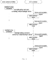
Fig. 1 is a schematic diagram of an embodiment of the SPI-based HUD backlight control method of the present invention; -
Fig. 2 is a schematic diagram of an embodiment of HUD backlight control using the method of the present invention; -
Fig. 3 is a schematic diagram showing the relationships among signals in an embodiment of the method according to the present invention. - In the following description, many specific details are expounded in order to give those skilled in the art a more comprehensive understanding of the present invention. However, it will be obvious to those skilled in the art that the implementation of the present invention may omit some of these specific details. Furthermore, it should be understood that the present invention is not limited to the specific embodiments presented. On the contrary, the use of any combination of the features and key elements below to implement the present invention may be considered, regardless of whether they relate to different embodiments. Furthermore, the aspects, features, embodiments and advantages below are merely explanatory, and should not be regarded as key elements or definitions of the claims, unless clearly stated in the claims.
- As
Fig. 1 shows, according to one embodiment of the present invention, the motor vehicle controller, after obtaining an environmental parameter (e.g. environmental light) and a user parameter (e.g. backlight brightness level), calculates backlight values according to these inputs. To enable the subsequently transmitted backlight values, when applied by the LED controller in the HUD, to be in synchrony with a video source signal of the HUD, the frequency of the video source signal should be used as the frequency of backlight value calculation. For example, if the video source signal is 60 Hz, the frequency of backlight value calculation should also be matched to this, i.e. one backlight value is calculated every 16.67 ms. When multiple backlight values have been obtained by multiple backlight value calculations, the motor vehicle controller transmits a backlight setting command containing multiple backlight values to the LED controller via a communication connection with the LED controller. In the backlight setting command, each backlight value is arranged in order according to the sequence of calculation. - Having received the backlight setting command, the LED controller will first of all apply a first backlight value after receiving a frame synchronization signal, then apply a second backlight value after receiving another frame synchronization signal, and so on, until all of the multiple backlight values in the backlight setting command have been applied. Then, after receiving another backlight setting command, the LED controller still operates in the manner described above (sequentially applying one backlight value in the backlight setting command each time a frame synchronization signal is obtained). It can be seen therefrom that in an embodiment of the present invention, the LED controller already has an available backlight value when receiving a frame synchronization signal; therefore, each time backlight control is performed based on a backlight value, the frequency of the video source signal can be matched, to achieve smoother backlight variation.
-
Fig. 2 provides a simplified view of an application structure of the method of the present invention in a vehicle-mounted HUD. Specifically, the chipset which controls the vehicle-mounted HUD may be a DLP chipset from TI. Referring toFig. 2 , the DLP chipset used in this example comprises: a DLP controller, a DMD controlled by the DLP controller, a Piccolo MCU LED controller, and a red/green/blue tri-colour LED controlled by the LED controller. Through control of the colour and brightness of LED backlight by the LED controller and control of the DMD by the DLP controller, content to be displayed is finally projected onto the vehicle windscreen or other display interface for head-up display. - In this example, the motor vehicle controller works in coordination with the LED controller, being connected to the LED controller via an SPI bus, to transmit backlight setting commands to the LED controller. Furthermore, the motor vehicle controller obtains CAN messages from a CAN bus via a CAN communication module. For example, when environmental parameters and/or user parameters come from other motor vehicle sub-systems (e.g. environmental temperature is obtained from an instrument), the motor vehicle controller can obtain these parameters by means of CAN messages. The basic process of calculating backlight values and transmitting backlight setting commands by the motor vehicle controller is as explained above, but is explained further below in conjunction with a specific video source signal example.
- Referring to
Fig. 3 , taking as an example the case of a video source signal of 60 Hz, which is relatively common at the present time, the motor vehicle controller calculates a backlight value once every 16.67 ms. After calculating three backlight values, the motor vehicle controller transmits the three backlight values obtained by calculation to the LED controller by means of a backlight setting command. Taking into consideration a real situation, there will be a time delay t1 between the time when the motor vehicle controller completes calculation of the three backlight values, and the SPI communication when the backlight setting command is transmitted. After calculating another three backlight values, the motor vehicle controller again transmits the three backlight values obtained by calculation to the LED controller by means of the next backlight setting command. Extending this principle, the motor vehicle controller transmits a backlight setting command to the LED controller every 50 ms. - After receiving the backlight setting command, the LED controller first of all sequentially stores the backlight value data in its own backlight setting queue, and awaits a frame synchronization signal from the DLP controller. Taking into consideration a real situation, there will also be a time delay t2 between the time when the LED controller receives the three backlight values in the backlight setting command, and the time when they begin to be applied after the frame synchronization signal is received. After receiving a frame synchronization signal, the LED controller will apply a backlight value. Since the frame synchronization signal frequency is also 60 Hz, the final backlight update frequency will also be 60 Hz, as long as the motor vehicle controller can ensure that a backlight setting command is transmitted to the LED controller every 50 ms. Thus, not only can the backlight update frequency match the video source signal, but also the motor vehicle controller now has more time for command transmission, so the difficulty of realizing smooth light adjustment is reduced. From a different perspective, the extension of the backlight setting command transmission period leaves time for other SPI commands, so that the success rate of transmission of other SPI commands is also increased.
- It must be explained that the frequency at which the motor vehicle controller calculates backlight values and transmits backlight setting commands is not necessarily limited to calculating three times and transmitting once; it could also be calculating six times and transmitting once, i.e. the motor vehicle controller transmits one backlight setting command containing six backlight values to the LED controller every 100 ms. If the effect of the time delay is able to meet requirements, the transmission of one backlight setting command containing twelve backlight values every 200 ms could also be considered. Therefore, the number of backlight values finally calculated before transmitting a backlight setting command must be determined according to actual circumstances. Since the video source signal in this example is 60 Hz, when the video source signal frequency changes, corresponding calculation and adjustment may also be made according to the explanation above.
- Although the present invention has been disclosed above by way of preferred embodiments, the present invention is not limited thereto. Changes and amendments of all kinds made within the spirit and scope of the present invention by any person skilled in the art shall be included in the scope of protection of the present invention. Thus the scope of protection of the present invention shall be the scope defined by the claims.
Claims (5)
- An SPI-based Head-Up Display (HUD) backlight control method, the HUD comprising: a motor vehicle controller, an LED device providing backlight for display and a controller thereof, wherein the motor vehicle controller transmits a backlight setting command to the LED controller in order to perform backlight control, characterized in that the method comprises:the motor vehicle controller using a frequency of a video source signal of the HUD as a backlight value calculation frequency, and calculating backlight values at this frequency;the motor vehicle controller placing multiple backlight values obtained by calculation into a backlight setting command, and transmitting same to the LED controller via an SPI bus;after obtaining the backlight setting command, the LED controller sequentially applying one backlight value in the backlight setting command each time a frame synchronization signal is obtained.
- The SPI-based HUD backlight control method as claimed in claim 1, characterized in that the frequency at which the backlight setting commands are transmitted is related to the number of backlight values.
- The SPI-based HUD backlight control method as claimed in claim 1, characterized in that the motor vehicle controller puts 3, 6 or 12 backlight values into one backlight setting command.
- The SPI-based HUD backlight control method as claimed in claim 1, characterized in that the frequency of the video source signal is 60 Hz; the frequency of the frame synchronization signal is 60 Hz.
- The SPI-based HUD backlight control method as claimed in claim 1, characterized in that the HUD also comprises: a digital light processing controller; the frame synchronization signal is transmitted to the LED controller by the digital light processing controller.
Applications Claiming Priority (2)
| Application Number | Priority Date | Filing Date | Title |
|---|---|---|---|
| CN201610080936.9A CN107045851B (en) | 2016-02-05 | 2016-02-05 | SPI-based backlight control method for head-up display |
| PCT/IB2017/000078 WO2017134515A1 (en) | 2016-02-05 | 2017-02-06 | Spi-based head-up display backlight control method |
Publications (2)
| Publication Number | Publication Date |
|---|---|
| EP3413298A1 true EP3413298A1 (en) | 2018-12-12 |
| EP3413298B1 EP3413298B1 (en) | 2019-10-16 |
Family
ID=58277302
Family Applications (1)
| Application Number | Title | Priority Date | Filing Date |
|---|---|---|---|
| EP17710791.9A Active EP3413298B1 (en) | 2016-02-05 | 2017-02-06 | Spi-based backlight control method for head-up display |
Country Status (6)
| Country | Link |
|---|---|
| US (1) | US10852536B2 (en) |
| EP (1) | EP3413298B1 (en) |
| JP (1) | JP6574067B2 (en) |
| KR (1) | KR102096200B1 (en) |
| CN (1) | CN107045851B (en) |
| WO (1) | WO2017134515A1 (en) |
Families Citing this family (4)
| Publication number | Priority date | Publication date | Assignee | Title |
|---|---|---|---|---|
| US10810773B2 (en) * | 2017-06-14 | 2020-10-20 | Dell Products, L.P. | Headset display control based upon a user's pupil state |
| JP6926929B2 (en) | 2017-10-18 | 2021-08-25 | 株式会社デンソー | Display control device |
| KR102733242B1 (en) * | 2022-05-25 | 2024-11-21 | 엘지전자 주식회사 | Image display apparatus |
| CN116092435A (en) * | 2022-12-07 | 2023-05-09 | 京东方晶芯科技有限公司 | SPI register, display substrate brightness setting method and display substrate |
Family Cites Families (17)
| Publication number | Priority date | Publication date | Assignee | Title |
|---|---|---|---|---|
| EP0570037A1 (en) * | 1992-05-15 | 1993-11-18 | General Motors Corporation | Head-up display system |
| US7408527B2 (en) | 2004-04-30 | 2008-08-05 | Infocus Corporation | Light emitting device driving method and projection apparatus so equipped |
| KR100791841B1 (en) | 2006-03-10 | 2008-01-07 | 삼성전자주식회사 | Apparatus and method for generating a backlight signal synchronized with a frame signal |
| JP5261127B2 (en) | 2008-10-15 | 2013-08-14 | 日立粉末冶金株式会社 | Coating composition for forming a negative electrode film and an electrode film of a lithium ion capacitor |
| WO2010098020A1 (en) | 2009-02-26 | 2010-09-02 | パナソニック株式会社 | Backlight apparatus and image display apparatus using the same |
| CN202093785U (en) * | 2011-04-27 | 2011-12-28 | 海尔集团公司 | LCD display equipment using LED backlight |
| CN102890917B (en) * | 2011-07-20 | 2015-09-02 | 乐金显示有限公司 | Backlight drive device and driving method, liquid crystal display and driving method thereof |
| JP5905229B2 (en) * | 2011-10-14 | 2016-04-20 | シャープ株式会社 | Signal generation circuit, backlight lighting timing control circuit, and signal generation method |
| CN102788294A (en) * | 2012-06-04 | 2012-11-21 | 苏州佳世达电通有限公司 | Display device, backlight device and backlight source control method |
| CN202855274U (en) * | 2012-09-27 | 2013-04-03 | 京东方科技集团股份有限公司 | Time-sequence control circuit, backlight scanning driving system and backlight source |
| KR20140059547A (en) * | 2012-11-08 | 2014-05-16 | 삼성전자주식회사 | Transparent display apparatus and method for controlling thereof |
| CN103606356A (en) * | 2013-11-06 | 2014-02-26 | 深圳市华星光电技术有限公司 | Liquid crystal display device and backlight driving method thereof |
| KR20150079004A (en) * | 2013-12-31 | 2015-07-08 | 에스엘 주식회사 | Dispay apparatus of vehicle and contolling method for the same |
| JP2015133251A (en) * | 2014-01-14 | 2015-07-23 | シャープ株式会社 | Dimmer, liquid crystal display device, and multi-display device |
| JP2016006496A (en) | 2014-05-28 | 2016-01-14 | 日本精機株式会社 | Light source device and display device |
| JP6390893B2 (en) * | 2014-06-16 | 2018-09-19 | 日本精機株式会社 | DMD display device, head-up display device |
| US10854002B2 (en) * | 2017-09-08 | 2020-12-01 | Verizon Patent And Licensing Inc. | Interactive vehicle window system including augmented reality overlays |
-
2016
- 2016-02-05 CN CN201610080936.9A patent/CN107045851B/en active Active
-
2017
- 2017-02-06 KR KR1020187021727A patent/KR102096200B1/en active Active
- 2017-02-06 WO PCT/IB2017/000078 patent/WO2017134515A1/en not_active Ceased
- 2017-02-06 EP EP17710791.9A patent/EP3413298B1/en active Active
- 2017-02-06 JP JP2018540747A patent/JP6574067B2/en active Active
-
2018
- 2018-07-31 US US16/050,826 patent/US10852536B2/en active Active
Also Published As
| Publication number | Publication date |
|---|---|
| US10852536B2 (en) | 2020-12-01 |
| WO2017134515A1 (en) | 2017-08-10 |
| JP6574067B2 (en) | 2019-09-11 |
| US20180335625A1 (en) | 2018-11-22 |
| CN107045851A (en) | 2017-08-15 |
| EP3413298B1 (en) | 2019-10-16 |
| JP2019507377A (en) | 2019-03-14 |
| KR102096200B1 (en) | 2020-04-01 |
| CN107045851B (en) | 2019-08-02 |
| KR20180098384A (en) | 2018-09-03 |
Similar Documents
| Publication | Publication Date | Title |
|---|---|---|
| US10852536B2 (en) | SPI-based head-up display backlight control method | |
| CN106527713B (en) | Three-dimensional data rendering system and method for VR | |
| WO2007056541A3 (en) | Apparatus and method for generating light from multi - primary colors | |
| CN104299601A (en) | Automatic regulating method and device for backlight brightness of splicing screen and splicing screen | |
| CN103024582B (en) | Multi-screen display control method and multi-display apparatus | |
| US10627821B2 (en) | Aerial shooting method and system using a drone | |
| CN105472358A (en) | Intelligent terminal about video image processing | |
| WO2015151457A1 (en) | Information display system | |
| CN111161574A (en) | Graphic programming online teaching system and online grouping teaching method | |
| JP7356464B2 (en) | Reducing the complexity of vehicle equipment control using back-channel transmission | |
| CN106909332B (en) | Display control method and system of spliced screen | |
| CN110321092A (en) | Synchronizing video output to a single display frequency | |
| KR20130036491A (en) | Method correcting time error when cluster for hybrid vehicle and avn system display data | |
| CN104391423B (en) | A kind of holographic three-dimensional projection arrangement and method based on nonlinear crystal | |
| US20050175311A1 (en) | Systems and methods for fiber optic glass panel color and image display | |
| JP2012060582A5 (en) | Reception device, transmission device, transmission / reception system, reception method, transmission method, and program | |
| CN109484176A (en) | A method of showing dynamic map on HUD | |
| WO2024229394A3 (en) | Virtual reality system for anticipated visual outcomes of eye treatments | |
| KR20120134438A (en) | Apparatus and method controlling display speed of energy flow in hybrid-vehicle | |
| CN107068021B (en) | ADC sampling method for head-up display based on frame synchronization | |
| KR20120025285A (en) | Apparatus and method displaying modulde information of hybrid-car using touch | |
| CN118101907A (en) | Projection method, projection device and storage medium | |
| JP5563187B2 (en) | Head-mounted display system | |
| CN201892846U (en) | Real-time controller for SD (secure digital) card | |
| CN119945639A (en) | A correction data transmission method and device, controller, and LED display screen system |
Legal Events
| Date | Code | Title | Description |
|---|---|---|---|
| STAA | Information on the status of an ep patent application or granted ep patent |
Free format text: STATUS: UNKNOWN |
|
| STAA | Information on the status of an ep patent application or granted ep patent |
Free format text: STATUS: THE INTERNATIONAL PUBLICATION HAS BEEN MADE |
|
| PUAI | Public reference made under article 153(3) epc to a published international application that has entered the european phase |
Free format text: ORIGINAL CODE: 0009012 |
|
| STAA | Information on the status of an ep patent application or granted ep patent |
Free format text: STATUS: REQUEST FOR EXAMINATION WAS MADE |
|
| 17P | Request for examination filed |
Effective date: 20180905 |
|
| AK | Designated contracting states |
Kind code of ref document: A1 Designated state(s): AL AT BE BG CH CY CZ DE DK EE ES FI FR GB GR HR HU IE IS IT LI LT LU LV MC MK MT NL NO PL PT RO RS SE SI SK SM TR |
|
| AX | Request for extension of the european patent |
Extension state: BA ME |
|
| DAV | Request for validation of the european patent (deleted) | ||
| DAX | Request for extension of the european patent (deleted) | ||
| GRAP | Despatch of communication of intention to grant a patent |
Free format text: ORIGINAL CODE: EPIDOSNIGR1 |
|
| STAA | Information on the status of an ep patent application or granted ep patent |
Free format text: STATUS: GRANT OF PATENT IS INTENDED |
|
| INTG | Intention to grant announced |
Effective date: 20190626 |
|
| GRAS | Grant fee paid |
Free format text: ORIGINAL CODE: EPIDOSNIGR3 |
|
| GRAA | (expected) grant |
Free format text: ORIGINAL CODE: 0009210 |
|
| STAA | Information on the status of an ep patent application or granted ep patent |
Free format text: STATUS: THE PATENT HAS BEEN GRANTED |
|
| AK | Designated contracting states |
Kind code of ref document: B1 Designated state(s): AL AT BE BG CH CY CZ DE DK EE ES FI FR GB GR HR HU IE IS IT LI LT LU LV MC MK MT NL NO PL PT RO RS SE SI SK SM TR |
|
| REG | Reference to a national code |
Ref country code: GB Ref legal event code: FG4D |
|
| REG | Reference to a national code |
Ref country code: CH Ref legal event code: EP |
|
| REG | Reference to a national code |
Ref country code: DE Ref legal event code: R096 Ref document number: 602017007899 Country of ref document: DE |
|
| REG | Reference to a national code |
Ref country code: IE Ref legal event code: FG4D |
|
| REG | Reference to a national code |
Ref country code: AT Ref legal event code: REF Ref document number: 1192059 Country of ref document: AT Kind code of ref document: T Effective date: 20191115 |
|
| REG | Reference to a national code |
Ref country code: NL Ref legal event code: MP Effective date: 20191016 |
|
| REG | Reference to a national code |
Ref country code: LT Ref legal event code: MG4D |
|
| REG | Reference to a national code |
Ref country code: AT Ref legal event code: MK05 Ref document number: 1192059 Country of ref document: AT Kind code of ref document: T Effective date: 20191016 |
|
| PG25 | Lapsed in a contracting state [announced via postgrant information from national office to epo] |
Ref country code: PT Free format text: LAPSE BECAUSE OF FAILURE TO SUBMIT A TRANSLATION OF THE DESCRIPTION OR TO PAY THE FEE WITHIN THE PRESCRIBED TIME-LIMIT Effective date: 20200217 Ref country code: FI Free format text: LAPSE BECAUSE OF FAILURE TO SUBMIT A TRANSLATION OF THE DESCRIPTION OR TO PAY THE FEE WITHIN THE PRESCRIBED TIME-LIMIT Effective date: 20191016 Ref country code: BG Free format text: LAPSE BECAUSE OF FAILURE TO SUBMIT A TRANSLATION OF THE DESCRIPTION OR TO PAY THE FEE WITHIN THE PRESCRIBED TIME-LIMIT Effective date: 20200116 Ref country code: NL Free format text: LAPSE BECAUSE OF FAILURE TO SUBMIT A TRANSLATION OF THE DESCRIPTION OR TO PAY THE FEE WITHIN THE PRESCRIBED TIME-LIMIT Effective date: 20191016 Ref country code: AT Free format text: LAPSE BECAUSE OF FAILURE TO SUBMIT A TRANSLATION OF THE DESCRIPTION OR TO PAY THE FEE WITHIN THE PRESCRIBED TIME-LIMIT Effective date: 20191016 Ref country code: SE Free format text: LAPSE BECAUSE OF FAILURE TO SUBMIT A TRANSLATION OF THE DESCRIPTION OR TO PAY THE FEE WITHIN THE PRESCRIBED TIME-LIMIT Effective date: 20191016 Ref country code: LV Free format text: LAPSE BECAUSE OF FAILURE TO SUBMIT A TRANSLATION OF THE DESCRIPTION OR TO PAY THE FEE WITHIN THE PRESCRIBED TIME-LIMIT Effective date: 20191016 Ref country code: LT Free format text: LAPSE BECAUSE OF FAILURE TO SUBMIT A TRANSLATION OF THE DESCRIPTION OR TO PAY THE FEE WITHIN THE PRESCRIBED TIME-LIMIT Effective date: 20191016 Ref country code: GR Free format text: LAPSE BECAUSE OF FAILURE TO SUBMIT A TRANSLATION OF THE DESCRIPTION OR TO PAY THE FEE WITHIN THE PRESCRIBED TIME-LIMIT Effective date: 20200117 Ref country code: PL Free format text: LAPSE BECAUSE OF FAILURE TO SUBMIT A TRANSLATION OF THE DESCRIPTION OR TO PAY THE FEE WITHIN THE PRESCRIBED TIME-LIMIT Effective date: 20191016 Ref country code: NO Free format text: LAPSE BECAUSE OF FAILURE TO SUBMIT A TRANSLATION OF THE DESCRIPTION OR TO PAY THE FEE WITHIN THE PRESCRIBED TIME-LIMIT Effective date: 20200116 |
|
| PG25 | Lapsed in a contracting state [announced via postgrant information from national office to epo] |
Ref country code: HR Free format text: LAPSE BECAUSE OF FAILURE TO SUBMIT A TRANSLATION OF THE DESCRIPTION OR TO PAY THE FEE WITHIN THE PRESCRIBED TIME-LIMIT Effective date: 20191016 Ref country code: RS Free format text: LAPSE BECAUSE OF FAILURE TO SUBMIT A TRANSLATION OF THE DESCRIPTION OR TO PAY THE FEE WITHIN THE PRESCRIBED TIME-LIMIT Effective date: 20191016 Ref country code: IS Free format text: LAPSE BECAUSE OF FAILURE TO SUBMIT A TRANSLATION OF THE DESCRIPTION OR TO PAY THE FEE WITHIN THE PRESCRIBED TIME-LIMIT Effective date: 20200224 |
|
| PG25 | Lapsed in a contracting state [announced via postgrant information from national office to epo] |
Ref country code: AL Free format text: LAPSE BECAUSE OF FAILURE TO SUBMIT A TRANSLATION OF THE DESCRIPTION OR TO PAY THE FEE WITHIN THE PRESCRIBED TIME-LIMIT Effective date: 20191016 |
|
| REG | Reference to a national code |
Ref country code: DE Ref legal event code: R097 Ref document number: 602017007899 Country of ref document: DE |
|
| PG2D | Information on lapse in contracting state deleted |
Ref country code: IS |
|
| PG25 | Lapsed in a contracting state [announced via postgrant information from national office to epo] |
Ref country code: DK Free format text: LAPSE BECAUSE OF FAILURE TO SUBMIT A TRANSLATION OF THE DESCRIPTION OR TO PAY THE FEE WITHIN THE PRESCRIBED TIME-LIMIT Effective date: 20191016 Ref country code: EE Free format text: LAPSE BECAUSE OF FAILURE TO SUBMIT A TRANSLATION OF THE DESCRIPTION OR TO PAY THE FEE WITHIN THE PRESCRIBED TIME-LIMIT Effective date: 20191016 Ref country code: ES Free format text: LAPSE BECAUSE OF FAILURE TO SUBMIT A TRANSLATION OF THE DESCRIPTION OR TO PAY THE FEE WITHIN THE PRESCRIBED TIME-LIMIT Effective date: 20191016 Ref country code: CZ Free format text: LAPSE BECAUSE OF FAILURE TO SUBMIT A TRANSLATION OF THE DESCRIPTION OR TO PAY THE FEE WITHIN THE PRESCRIBED TIME-LIMIT Effective date: 20191016 Ref country code: RO Free format text: LAPSE BECAUSE OF FAILURE TO SUBMIT A TRANSLATION OF THE DESCRIPTION OR TO PAY THE FEE WITHIN THE PRESCRIBED TIME-LIMIT Effective date: 20191016 Ref country code: IS Free format text: LAPSE BECAUSE OF FAILURE TO SUBMIT A TRANSLATION OF THE DESCRIPTION OR TO PAY THE FEE WITHIN THE PRESCRIBED TIME-LIMIT Effective date: 20200216 |
|
| PLBE | No opposition filed within time limit |
Free format text: ORIGINAL CODE: 0009261 |
|
| STAA | Information on the status of an ep patent application or granted ep patent |
Free format text: STATUS: NO OPPOSITION FILED WITHIN TIME LIMIT |
|
| RAP2 | Party data changed (patent owner data changed or rights of a patent transferred) |
Owner name: CONTINENTAL AUTOMOTIVE GMBH |
|
| PG25 | Lapsed in a contracting state [announced via postgrant information from national office to epo] |
Ref country code: IT Free format text: LAPSE BECAUSE OF FAILURE TO SUBMIT A TRANSLATION OF THE DESCRIPTION OR TO PAY THE FEE WITHIN THE PRESCRIBED TIME-LIMIT Effective date: 20191016 Ref country code: SK Free format text: LAPSE BECAUSE OF FAILURE TO SUBMIT A TRANSLATION OF THE DESCRIPTION OR TO PAY THE FEE WITHIN THE PRESCRIBED TIME-LIMIT Effective date: 20191016 Ref country code: SM Free format text: LAPSE BECAUSE OF FAILURE TO SUBMIT A TRANSLATION OF THE DESCRIPTION OR TO PAY THE FEE WITHIN THE PRESCRIBED TIME-LIMIT Effective date: 20191016 |
|
| 26N | No opposition filed |
Effective date: 20200717 |
|
| REG | Reference to a national code |
Ref country code: CH Ref legal event code: PL |
|
| REG | Reference to a national code |
Ref country code: BE Ref legal event code: MM Effective date: 20200229 |
|
| PG25 | Lapsed in a contracting state [announced via postgrant information from national office to epo] |
Ref country code: MC Free format text: LAPSE BECAUSE OF FAILURE TO SUBMIT A TRANSLATION OF THE DESCRIPTION OR TO PAY THE FEE WITHIN THE PRESCRIBED TIME-LIMIT Effective date: 20191016 Ref country code: LU Free format text: LAPSE BECAUSE OF NON-PAYMENT OF DUE FEES Effective date: 20200206 |
|
| PG25 | Lapsed in a contracting state [announced via postgrant information from national office to epo] |
Ref country code: CH Free format text: LAPSE BECAUSE OF NON-PAYMENT OF DUE FEES Effective date: 20200229 Ref country code: LI Free format text: LAPSE BECAUSE OF NON-PAYMENT OF DUE FEES Effective date: 20200229 Ref country code: SI Free format text: LAPSE BECAUSE OF FAILURE TO SUBMIT A TRANSLATION OF THE DESCRIPTION OR TO PAY THE FEE WITHIN THE PRESCRIBED TIME-LIMIT Effective date: 20191016 |
|
| PG25 | Lapsed in a contracting state [announced via postgrant information from national office to epo] |
Ref country code: IE Free format text: LAPSE BECAUSE OF NON-PAYMENT OF DUE FEES Effective date: 20200206 |
|
| PG25 | Lapsed in a contracting state [announced via postgrant information from national office to epo] |
Ref country code: BE Free format text: LAPSE BECAUSE OF NON-PAYMENT OF DUE FEES Effective date: 20200229 |
|
| GBPC | Gb: european patent ceased through non-payment of renewal fee |
Effective date: 20210206 |
|
| PG25 | Lapsed in a contracting state [announced via postgrant information from national office to epo] |
Ref country code: GB Free format text: LAPSE BECAUSE OF NON-PAYMENT OF DUE FEES Effective date: 20210206 |
|
| PG25 | Lapsed in a contracting state [announced via postgrant information from national office to epo] |
Ref country code: TR Free format text: LAPSE BECAUSE OF FAILURE TO SUBMIT A TRANSLATION OF THE DESCRIPTION OR TO PAY THE FEE WITHIN THE PRESCRIBED TIME-LIMIT Effective date: 20191016 Ref country code: MT Free format text: LAPSE BECAUSE OF FAILURE TO SUBMIT A TRANSLATION OF THE DESCRIPTION OR TO PAY THE FEE WITHIN THE PRESCRIBED TIME-LIMIT Effective date: 20191016 Ref country code: CY Free format text: LAPSE BECAUSE OF FAILURE TO SUBMIT A TRANSLATION OF THE DESCRIPTION OR TO PAY THE FEE WITHIN THE PRESCRIBED TIME-LIMIT Effective date: 20191016 |
|
| PG25 | Lapsed in a contracting state [announced via postgrant information from national office to epo] |
Ref country code: MK Free format text: LAPSE BECAUSE OF FAILURE TO SUBMIT A TRANSLATION OF THE DESCRIPTION OR TO PAY THE FEE WITHIN THE PRESCRIBED TIME-LIMIT Effective date: 20191016 |
|
| REG | Reference to a national code |
Ref country code: DE Ref legal event code: R081 Ref document number: 602017007899 Country of ref document: DE Owner name: CONTINENTAL AUTOMOTIVE TECHNOLOGIES GMBH, DE Free format text: FORMER OWNER: CONTINENTAL AUTOMOTIVE GMBH, 30165 HANNOVER, DE Ref country code: DE Ref legal event code: R081 Ref document number: 602017007899 Country of ref document: DE Owner name: AUMOVIO GERMANY GMBH, DE Free format text: FORMER OWNER: CONTINENTAL AUTOMOTIVE GMBH, 30165 HANNOVER, DE |
|
| P01 | Opt-out of the competence of the unified patent court (upc) registered |
Effective date: 20230522 |
|
| REG | Reference to a national code |
Ref country code: DE Ref legal event code: R081 Ref document number: 602017007899 Country of ref document: DE Owner name: CONTINENTAL AUTOMOTIVE TECHNOLOGIES GMBH, DE Free format text: FORMER OWNER: CONTINENTAL AUTOMOTIVE TECHNOLOGIES GMBH, 30165 HANNOVER, DE Ref country code: DE Ref legal event code: R081 Ref document number: 602017007899 Country of ref document: DE Owner name: AUMOVIO GERMANY GMBH, DE Free format text: FORMER OWNER: CONTINENTAL AUTOMOTIVE TECHNOLOGIES GMBH, 30165 HANNOVER, DE |
|
| REG | Reference to a national code |
Ref country code: DE Ref legal event code: R081 Ref document number: 602017007899 Country of ref document: DE Owner name: AUMOVIO GERMANY GMBH, DE Free format text: FORMER OWNER: CONTINENTAL AUTOMOTIVE TECHNOLOGIES GMBH, 30175 HANNOVER, DE |
|
| PGFP | Annual fee paid to national office [announced via postgrant information from national office to epo] |
Ref country code: DE Payment date: 20260228 Year of fee payment: 10 |
|
| PGFP | Annual fee paid to national office [announced via postgrant information from national office to epo] |
Ref country code: FR Payment date: 20260227 Year of fee payment: 10 |