EP3413143A2 - Mechanical component, timepiece, and manufacturing method of mechanical component - Google Patents
Mechanical component, timepiece, and manufacturing method of mechanical component Download PDFInfo
- Publication number
- EP3413143A2 EP3413143A2 EP18176269.1A EP18176269A EP3413143A2 EP 3413143 A2 EP3413143 A2 EP 3413143A2 EP 18176269 A EP18176269 A EP 18176269A EP 3413143 A2 EP3413143 A2 EP 3413143A2
- Authority
- EP
- European Patent Office
- Prior art keywords
- holder
- axle member
- escape wheel
- tapered
- recessed portion
- Prior art date
- Legal status (The legal status is an assumption and is not a legal conclusion. Google has not performed a legal analysis and makes no representation as to the accuracy of the status listed.)
- Withdrawn
Links
- 238000004519 manufacturing process Methods 0.000 title claims description 27
- 230000007423 decrease Effects 0.000 claims description 19
- 238000000034 method Methods 0.000 claims description 7
- 239000000463 material Substances 0.000 description 28
- 238000004804 winding Methods 0.000 description 13
- 230000004323 axial length Effects 0.000 description 11
- XUIMIQQOPSSXEZ-UHFFFAOYSA-N Silicon Chemical compound [Si] XUIMIQQOPSSXEZ-UHFFFAOYSA-N 0.000 description 10
- 229920002120 photoresistant polymer Polymers 0.000 description 10
- 229910052710 silicon Inorganic materials 0.000 description 10
- 239000010703 silicon Substances 0.000 description 10
- 230000007246 mechanism Effects 0.000 description 9
- 238000005530 etching Methods 0.000 description 8
- 229910052751 metal Inorganic materials 0.000 description 8
- 239000002184 metal Substances 0.000 description 8
- VYPSYNLAJGMNEJ-UHFFFAOYSA-N Silicium dioxide Chemical compound O=[Si]=O VYPSYNLAJGMNEJ-UHFFFAOYSA-N 0.000 description 6
- 238000005520 cutting process Methods 0.000 description 5
- 230000004048 modification Effects 0.000 description 5
- 238000012986 modification Methods 0.000 description 5
- 238000000227 grinding Methods 0.000 description 4
- 230000003647 oxidation Effects 0.000 description 4
- 238000007254 oxidation reaction Methods 0.000 description 4
- 238000000206 photolithography Methods 0.000 description 4
- 229910000975 Carbon steel Inorganic materials 0.000 description 3
- 239000010962 carbon steel Substances 0.000 description 3
- 230000000694 effects Effects 0.000 description 3
- 230000002093 peripheral effect Effects 0.000 description 3
- 230000008901 benefit Effects 0.000 description 2
- 238000000708 deep reactive-ion etching Methods 0.000 description 2
- 239000007769 metal material Substances 0.000 description 2
- 238000003825 pressing Methods 0.000 description 2
- 239000000377 silicon dioxide Substances 0.000 description 2
- 229910052814 silicon oxide Inorganic materials 0.000 description 2
- 229910052715 tantalum Inorganic materials 0.000 description 2
- GUVRBAGPIYLISA-UHFFFAOYSA-N tantalum atom Chemical compound [Ta] GUVRBAGPIYLISA-UHFFFAOYSA-N 0.000 description 2
- WFKWXMTUELFFGS-UHFFFAOYSA-N tungsten Chemical compound [W] WFKWXMTUELFFGS-UHFFFAOYSA-N 0.000 description 2
- 229910052721 tungsten Inorganic materials 0.000 description 2
- 239000010937 tungsten Substances 0.000 description 2
- GRYLNZFGIOXLOG-UHFFFAOYSA-N Nitric acid Chemical compound O[N+]([O-])=O GRYLNZFGIOXLOG-UHFFFAOYSA-N 0.000 description 1
- 239000000853 adhesive Substances 0.000 description 1
- 230000001070 adhesive effect Effects 0.000 description 1
- 238000004380 ashing Methods 0.000 description 1
- QVGXLLKOCUKJST-UHFFFAOYSA-N atomic oxygen Chemical compound [O] QVGXLLKOCUKJST-UHFFFAOYSA-N 0.000 description 1
- 239000013078 crystal Substances 0.000 description 1
- 230000018109 developmental process Effects 0.000 description 1
- 229910021421 monocrystalline silicon Inorganic materials 0.000 description 1
- 239000003960 organic solvent Substances 0.000 description 1
- 229910052760 oxygen Inorganic materials 0.000 description 1
- 239000001301 oxygen Substances 0.000 description 1
- 230000008569 process Effects 0.000 description 1
- 239000010979 ruby Substances 0.000 description 1
- 229910001750 ruby Inorganic materials 0.000 description 1
- 235000012239 silicon dioxide Nutrition 0.000 description 1
- 238000004528 spin coating Methods 0.000 description 1
- 238000005507 spraying Methods 0.000 description 1
- 238000003892 spreading Methods 0.000 description 1
- 230000007480 spreading Effects 0.000 description 1
- 239000000758 substrate Substances 0.000 description 1
- 238000001039 wet etching Methods 0.000 description 1
Images


Classifications
-
- G—PHYSICS
- G04—HOROLOGY
- G04B—MECHANICALLY-DRIVEN CLOCKS OR WATCHES; MECHANICAL PARTS OF CLOCKS OR WATCHES IN GENERAL; TIME PIECES USING THE POSITION OF THE SUN, MOON OR STARS
- G04B1/00—Driving mechanisms
- G04B1/10—Driving mechanisms with mainspring
- G04B1/16—Barrels; Arbors; Barrel axles
-
- G—PHYSICS
- G04—HOROLOGY
- G04B—MECHANICALLY-DRIVEN CLOCKS OR WATCHES; MECHANICAL PARTS OF CLOCKS OR WATCHES IN GENERAL; TIME PIECES USING THE POSITION OF THE SUN, MOON OR STARS
- G04B13/00—Gearwork
- G04B13/02—Wheels; Pinions; Spindles; Pivots
- G04B13/021—Wheels; Pinions; Spindles; Pivots elastic fitting with a spindle, axis or shaft
- G04B13/022—Wheels; Pinions; Spindles; Pivots elastic fitting with a spindle, axis or shaft with parts made of hard material, e.g. silicon, diamond, sapphire, quartz and the like
-
- F—MECHANICAL ENGINEERING; LIGHTING; HEATING; WEAPONS; BLASTING
- F16—ENGINEERING ELEMENTS AND UNITS; GENERAL MEASURES FOR PRODUCING AND MAINTAINING EFFECTIVE FUNCTIONING OF MACHINES OR INSTALLATIONS; THERMAL INSULATION IN GENERAL
- F16D—COUPLINGS FOR TRANSMITTING ROTATION; CLUTCHES; BRAKES
- F16D1/00—Couplings for rigidly connecting two coaxial shafts or other movable machine elements
- F16D1/10—Quick-acting couplings in which the parts are connected by simply bringing them together axially
- F16D1/108—Quick-acting couplings in which the parts are connected by simply bringing them together axially having retaining means rotating with the coupling and acting by interengaging parts, i.e. positive coupling
- F16D1/116—Quick-acting couplings in which the parts are connected by simply bringing them together axially having retaining means rotating with the coupling and acting by interengaging parts, i.e. positive coupling the interengaging parts including a continuous or interrupted circumferential groove in the surface of one of the coupling parts
-
- G—PHYSICS
- G04—HOROLOGY
- G04B—MECHANICALLY-DRIVEN CLOCKS OR WATCHES; MECHANICAL PARTS OF CLOCKS OR WATCHES IN GENERAL; TIME PIECES USING THE POSITION OF THE SUN, MOON OR STARS
- G04B13/00—Gearwork
- G04B13/02—Wheels; Pinions; Spindles; Pivots
- G04B13/025—Wheels; Pinions; Spindles; Pivots with elastic means between the toothing and the hub of a toothed wheel
-
- G—PHYSICS
- G04—HOROLOGY
- G04B—MECHANICALLY-DRIVEN CLOCKS OR WATCHES; MECHANICAL PARTS OF CLOCKS OR WATCHES IN GENERAL; TIME PIECES USING THE POSITION OF THE SUN, MOON OR STARS
- G04B15/00—Escapements
- G04B15/14—Component parts or constructional details, e.g. construction of the lever or the escape wheel
-
- F—MECHANICAL ENGINEERING; LIGHTING; HEATING; WEAPONS; BLASTING
- F16—ENGINEERING ELEMENTS AND UNITS; GENERAL MEASURES FOR PRODUCING AND MAINTAINING EFFECTIVE FUNCTIONING OF MACHINES OR INSTALLATIONS; THERMAL INSULATION IN GENERAL
- F16D—COUPLINGS FOR TRANSMITTING ROTATION; CLUTCHES; BRAKES
- F16D1/00—Couplings for rigidly connecting two coaxial shafts or other movable machine elements
- F16D1/10—Quick-acting couplings in which the parts are connected by simply bringing them together axially
- F16D2001/103—Quick-acting couplings in which the parts are connected by simply bringing them together axially the torque is transmitted via splined connections
-
- F—MECHANICAL ENGINEERING; LIGHTING; HEATING; WEAPONS; BLASTING
- F16—ENGINEERING ELEMENTS AND UNITS; GENERAL MEASURES FOR PRODUCING AND MAINTAINING EFFECTIVE FUNCTIONING OF MACHINES OR INSTALLATIONS; THERMAL INSULATION IN GENERAL
- F16D—COUPLINGS FOR TRANSMITTING ROTATION; CLUTCHES; BRAKES
- F16D2250/00—Manufacturing; Assembly
- F16D2250/0084—Assembly or disassembly
Definitions
- the present invention relates to a mechanical component, a timepiece, and a manufacturing method of a mechanical component.
- a mechanical timepiece is equipped with numerous mechanical components represented by wheels.
- the mechanical component such as the wheel is fixed (held) by inserting an axle member into a through-hole (holder) disposed at the center of a rotary member whose outer periphery has a plurality of teeth.
- the mechanical component is formed by carrying out machine work for a metal material.
- a base material containing silicon has been used as a material of the mechanical component for a timepiece.
- the mechanical component made of the silicon serving as the base material is lighter in weight than the mechanical component made of metal serving as the base material.
- an inertial force of the mechanical component can be reduced. Accordingly, improved efficiency in transferring energy is expected.
- the silicon allows various shapes to be freely formed using a photolithography and etching technique. Therefore, there is an advantage in that processing accuracy of the mechanical component can be improved by using the silicon as the base material.
- JP-A-2012-167808 discloses a mechanical component (third wheel & pinion) having a rotary member (third wheel) made of the silicon serving as the base material.
- the silicon is more brittle and more likely to fracture compared to metal. Accordingly, if stress applied to the rotary member is strong when an axle member (third pinion) is fitted into a through-hole of the rotary member, the rotary member may be damaged in some cases.
- the mechanical component disclosed in JP-A-2012-167808 adopts a structure in which a stress relaxation layer made of metal is disposed on an inner peripheral surface of the through-hole of the rotary member so that the stress relaxation layer is brought into contact with an outer peripheral surface of the axle member.
- a metal film is formed on an entire front surface of the rotary member formed of the silicon serving as the base material. Thereafter, the metal film of a portion other than the inner peripheral surface of the through-hole of the rotary member is removed using a photolithography or etching technique, thereby forming the stress relaxation layer. Therefore, in addition to a step of forming the rotary member, it is necessary to provide a step of forming the metal film and a step of removing a portion of the metal film. Consequently, manufacturing man-hours required for the mechanical component may increase, thereby leading to a possibility of increase in manufacturing cost.
- the axle member is formed by carrying out machine work such as cutting work and grinding work. Accordingly, in some cases, there are variations in a size of an outer diameter or an axial length of a portion of the axle member fitted into the through-hole of the rotary member, that is, a portion in contact with the stress relaxation layer. In contrast, the stress relaxation layer is the metal film. Accordingly, if the variations are significant when the machine work is carried out for the axle member, it is difficult to absorb the variations. For example, if the outer diameter of the axle member is small, the stress is insufficient when the rotary member and the axle member are fitted to each other, and the axle member consequently falls out of the rotary member.
- An advantage of some aspects of the invention is to solve at least a part of the problems described above, and the invention can be implemented as the following forms or application examples.
- a mechanical component according to this application example includes an axle member, and a rotary member that has a holder for holding the axle member, in which the axle member has a recessed portion to be fitted to the holder, and a first tapered portion inclined in an axial direction of the axle member is disposed in a portion where the recessed portion is in contact with the holder.
- the axle member has the recessed portion to be fitted to the holder of the rotary member.
- the first tapered portion is disposed in the portion where the recessed portion is in contact with the holder. In a case where the first tapered portion is not disposed in the recessed portion, if an axial length of the recessed portion is shorter than a thickness of the holder, the holder does not enter the recessed portion. If the axial length of the recessed portion is longer than the thickness of the holder, the holder and the recessed portion are unsteadily fitted to each other.
- the first tapered portion inclined in the axial direction is disposed in the recessed portion.
- the holder is fitted into the recessed portion by coming into contact with any position of the first tapered portion. Therefore, without disposing a stress relaxation layer in the rotary member, the holder is reliably fitted into the recessed portion, thereby enabling the rotary member and the axle member to be fixed to each other. In this manner, it is possible to prevent an increase in manufacturing man-hours of the mechanical component and a poor manufacturing yield of the mechanical component.
- the first tapered portion is formed so that a diameter of the first tapered portion decreases as the first tapered portion is closer from one end side to the other end side in the recessed portion.
- the first tapered portion is formed so that the diameter of the first tapered portion decreases as the first tapered portion is closer from one end side to the other end side in the recessed portion. Accordingly, a cross-sectional shape of the first tapered portion serves as an inclined surface facing the other end side in the axial direction. In this manner, stress acting from the first tapered portion toward the other end side is applied to the holder fitted into the recessed portion. Therefore, it is possible to prevent the axle member from falling out of the rotary member.
- the axle member has a second tapered portion formed on a side opposite to the other end with respect to the recessed portion so that a diameter of the second tapered portion decreases as the second tapered portion is farther away from the recessed portion, and an inclination angle of the first tapered portion in the axial direction is larger than an inclination angle of the second tapered portion in the axial direction.
- the axle member has the second tapered portion formed on the side opposite to the other end with respect to the recessed portion so that the diameter of the second tapered portion decreases as the second tapered portion is farther away from the recessed portion, that is, the diameter increases as the second tapered portion is closer to the recessed portion. Therefore, if the axle member is inserted into the rotary member from the side of the second tapered portion, the holder of the rotary member spreads outward as the holder is closer to the recessed portion in the second tapered portion. In this case, the inclination angle of the second tapered portion in the axial direction is smaller than the inclination angle of the first tapered portion.
- the stress applied to the holder gradually increases in a direction in which the axle member is inserted into the rotary member. Therefore, the axle member can be easily inserted into the rotary member.
- the inclination angle of the first tapered portion in the axial direction is larger than the inclination angle of the second tapered portion. Accordingly, the stress applied to the holder rapidly increases in a direction in which the axle member falls out of the rotary member. Therefore, it is possible to prevent the axle member from falling out of the rotary member.
- an outer diameter of the axle member in a boundary portion between the recessed portion and the second tapered portion is larger than an outer diameter of the axle member in a portion where the holder is in contact with the first tapered portion.
- the outer diameter of the axle member in the boundary portion between the recessed portion having the first tapered portion and the second tapered portion is larger than the outer diameter of the portion where the holder is in contact with the first tapered portion. Accordingly, the holder fitted into the recessed portion is less likely to return to the second tapered portion side. Therefore, it is possible to prevent the axle member from falling out of the rotary member.
- the axle member has a projection portion in contact with the holder, on the other end side of the recessed portion.
- the holder of the rotary member is in contact with the first tapered portion disposed in the recessed portion, and is in contact with the projection portion disposed on the other end side of the recessed portion. Accordingly, the stress acting from the first tapered portion toward the projection portion is applied to the holder. Therefore, it is possible to effectively prevent the axle member from falling out of the rotary member.
- the rotary member has a rim portion having a plurality of teeth
- the holder has a first holder extending in a direction from the rim portion toward the axle member, and a second holder having a first portion extending in a direction intersecting the first holder and a second portion extending in the direction from the first portion toward the axle member, and the second portion is in contact with the first tapered portion.
- the first portion extending in the direction intersecting the first holder is bent to the first holder extending in the direction from the rim portion toward the axle member. Accordingly, the second portion can be deformed in the direction in which the second portion faces the axle member, which is the extending direction of the second portion, and in the direction in which the second portion faces outward from the axle member. In this manner, even in a case where the outer diameter of the axle member in the recessed portion varies, the stress applied to the holder of the rotary member can be relaxed. Accordingly, damage to the rotary member can be prevented. The first portion is bent, and the second portion is deformed, thereby generating the stress. The stress enables the axle member to be located and held at the center of the rotary member.
- the second holder has a plurality of the first portions.
- the plurality of first portions connecting the first holder and the second portion to each other are likely to be bent in the direction from the rim portion toward the axle member in a plane configured to include the first holder and the second holder (the first portion and the second portion) .
- the plurality of first portions are provided in this way. Accordingly, even in a case where the outer diameter of the axle member in the recessed portion varies, it is possible to sufficiently obtain the stress for holding the axle member at the center of the rotary member.
- the plurality of first portions are less likely to be bent in the axial direction (longitudinal direction of the axle member) intersecting the plane configured to include the first holder and the second holder (the first portion and the second portion). Accordingly, the second portion is likely to be deformed in the direction toward the axle member and in the direction outward from the axle member. However, the second portion is less likely to be deformed in the axial direction. Therefore, the rotary member and the axle member can be reliably fixed to each other, and the rotary member can be prevented from being inclined from or falling out of the axle member.
- a timepiece according to this application example includes the mechanical component described above.
- the timepiece includes the mechanical component described above in any one of the application examples. Therefore, it is possible to provide a highly accurate timepiece which is excellent in quality and cost competitiveness.
- a manufacturing method of a mechanical component includes forming a holder for holding an axle member in a rotary member, forming a recessed portion to be fitted to the holder in the axle member, and inserting the axle member into the rotary member so that the holder is fitted into the recessed portion, in which in the forming of the recessed portion, a first tapered portion is formed so that a diameter of the first tapered portion decreases as the first tapered portion is closer from one end side to the other end side in the recessed portion, and an inner diameter of the holder formed in the forming of the holder is smaller than an outer diameter of the axle member in a portion where the holder fitted into the recessed portion in fitting the holder into the recessed portion is in contact with the first tapered portion.
- the first tapered portion is formed in the recessed portion of the axle member. Accordingly, in a case where the axial length of the recessed portion varies, if the axle member is inserted into the rotary member in fitting the holder into the recessed portion, the holder is fitted into the recessed portion by coming into contact with any position of the first tapered portion. Accordingly, without disposing the stress relaxation layer in the rotary member, the holder is reliably fitted into the recessed portion, thereby enabling the rotary member and the axle member to be fixed to each other. In this manner, it is possible to prevent an increase in manufacturing man-hours of the mechanical component and a poor manufacturing yield of the mechanical component.
- the inner diameter of the holder formed in the forming of the holder is smaller than the outer diameter of the axle member in the portion where the holder fitted into the recessed portion in fitting the holder into the recessed portion is in contact with the first tapered portion. Accordingly, if the holder is fitted into the recessed portion, the stress spreading outward in the radial direction is applied from the first tapered portion to the holder. Then, the cross-sectional shape of the first tapered portion serves as the inclined surface which faces the other end side in the axial direction, for the holder fitting to the recessed portion. Therefore, the stress acting from the first tapered portion toward the other end side is applied to the holder fitted into the recessed portion. In this manner, it is possible to prevent the axle member from falling out of the rotary member.
- a second tapered portion is formed on a side opposite to the other end with respect to the recessed portion so that a diameter of the second tapered portion decreases as the second tapered portion is farther away from the recessed portion, and an outer diameter of the axle member in a boundary portion between the recessed portion and the second tapered portion is larger than an outer diameter of the axle member in a portion where the holder fitted into the recessed portion in fitting the holder into the recessed portion is in contact with the first tapered portion.
- the axle member has the second tapered portion formed on the side opposite to the other end with respect to the recessed portion having the first tapered portion so that the diameter of the second tapered portion increases as the second tapered portion is closer to the recessed portion. Accordingly, if the axle member is inserted into the rotary member from the side of the second tapered portion, the holder spreads outward as the holder is closer to the recessed portion in the second tapered portion. Therefore, the axle member can be easily inserted into the rotary member.
- the outer diameter of the axle member in the boundary portion between the recessed portion and the second tapered portion is larger than the outer diameter of the axle member in the portion where the holder fitted into the recessed portion is in contact with the first tapered portion. Therefore, the holder fitted into the recessed portion having the first tapered portion after crossing the boundary portion from the second tapered portion is less likely to return to the second tapered portion side. In this manner, it is possible to prevent the axle member from falling out of the rotary member.
- a mechanical timepiece will be treated as an example of a timepiece according to the invention.
- an escape wheel & pinion serving as one of wheels configuring timepiece components in a movement of the mechanical timepiece will be described as an example.
- each layer or each member is illustrated using scales different from actual scales.
- Fig. 1 is a plan view illustrating a front side of the movement of the mechanical timepiece according to the embodiment.
- the mechanical timepiece 1 according to the embodiment is configured to include a movement 10 and a casing (not illustrated) for accommodating the movement 10.
- a side outward of a paper surface in Fig. 1 is referred to as a front side, and a side inward thereof is referred to as a rear side.
- the movement 10 has a main plate 11 configuring a substrate.
- a dial (not illustrated) is located on the rear side of the main plate 11.
- a wheel train incorporated on the front side of the movement 10 is referred to as a front train wheel, and a wheel train incorporated on the rear side of the movement 10 is referred to as a rear wheel train.
- the main plate 11 has a winding stem guide hole 11a formed therein, and a winding stem 12 is rotatably incorporated in the winding stem guide hole 11a.
- the winding stem 12 is determined to have an axial position by a switching device having a setting lever 13, a yoke 14, a yoke spring 15, and a setting lever jumper 16.
- a winding pinion 17 is rotatably disposed in a guide axle portion of the winding stem 12.
- the winding stem 12 is rotated in a state where the winding stem 12 is located at a first winding stem position (0- th stage) closest to an inner side of the movement 10 along a rotation axis direction
- the winding pinion 17 is rotated via rotation of a clutch wheel (not illustrated).
- the winding pinion 17 is rotated, thereby rotating a crown wheel 20 meshing with the winding pinion 17.
- the crown wheel 20 is rotated, thereby rotating a ratchet wheel 21 meshing with the crown wheel 20.
- the ratchet wheel 21 is rotated, thereby winding a mainspring (power source) (not illustrated) accommodated in a movement barrel 22.
- the front train wheel of the movement 10 is configured to include a center wheel & pinion (mechanical component) 25, a third wheel & pinion (mechanical component) 26, and a second wheel & pinion (mechanical component) 27 which are so-called wheels & pinions, and has a function to transmit a rotational force of the movement barrel 22.
- An escapement mechanism 30 and a speed control mechanism 31 for controlling the rotation of the front train wheel are arranged on the front side of the movement 10.
- the center wheel & pinion 25 meshes with the movement barrel 22.
- the third wheel & pinion 26 meshes with the center wheel & pinion 25.
- the second wheel & pinion 27 meshes with the third wheel & pinion 26.
- the escapement mechanism 30 controls the rotation of the above-described front train wheel, and includes an escape wheel & pinion (mechanical component) 35 meshing with the second wheel & pinion 27 and a pallet fork (mechanical component) 36 which causes the escape wheel & pinion 35 to escape so as to be regularly rotated.
- the speed control mechanism 31 controls speed of the above-described escapement mechanism 30, and includes a balance with hairspring (mechanical component) 40.
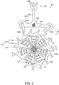
- Fig. 2 is a plan view of the escapement mechanism according to the embodiment.
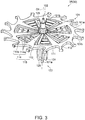
- Fig. 3 is a perspective view when the escape wheel & pinion serving as the mechanical component according to the embodiment is viewed from the front surface side.
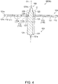
- Fig. 4 is a sectional view of the escape wheel & pinion which is taken along line A-A' in Fig. 2 .
- Fig. 5 is a partial sectional view obtained by enlarging a C-portion illustrated in Fig. 4 .
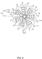
- Fig. 6 is a plan view of the escape wheel portion serving as a rotary member according to the embodiment.
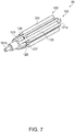
- Fig. 7 is a perspective view of an axle member according to the embodiment.
- Fig. 8 is a sectional view of the axle member which is taken along line B-B' in Fig. 2 .
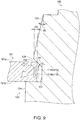
- Fig. 9 is a partial sectional view for describing fitting between the escape wheel portion and the axle member.
- the escape wheel & pinion 35 included in the escapement mechanism 30 includes an escape wheel portion 101 as a rotary member and an axle member (rotary axle) 102 coaxially (axis O1) fixed to the escape wheel portion 101.
- a longitudinal direction along the axis O1 of the escape wheel portion 101 and the axle member 102 is simply referred to as an axial direction.
- a front surface 101a and a rear surface 101b of the escape wheel portion 101 are orthogonal to the axis O1 (line passing the center of the axle member 102 along the axial direction) .
- a direction passing through the axis O1 in a plane parallel to the front surface 101a and the rear surface 101b of the escape wheel portion 101 is referred to as a radial direction.
- a direction in which the escape wheel portion 101 and the axle member 102 turn around the axis O1 is referred to as a circumferential direction.
- the front surface 101a and the rear surface 101b (refer to Fig. 3 ) have a plate shape which is formed into a flat surface and has a uniform thickness over the entire surface.
- the escape wheel portion 101 is made of a material having a crystal orientation such as single crystal silicon, or a metal material.
- the escape wheel portion 101 has a rim portion 111 having a plurality of tooth portions 112 and a holder 115 for holding the axle member 102.
- the rim portion 111 is the annular portion of an outer edge of the escape wheel portion 101.
- the tooth portion 112 protrudes outward from an outer periphery of the rim portion 111, and is formed in a special hook shape.
- the pallets 144a and 144b of a pallet fork 36 (to be described later) come into contact with a tip of the plurality of tooth portions 112.
- the holder 115 is located on the axle member 102 side with respect to the rim portion 111.
- the escape wheel portion 101 has seven holders 115.
- the holders 115 are located at seven positions at an equal pitch of 360°/7 in the circumferential direction of the annular rim portion 111.
- the number of the holders 115 may be in a range of three to seven, or may be seven or more, and is not particularly limited.
- the holder 115 has a first holder 113 extending from the rim portion 111 and a second holder 114 branched from the first holder 113.
- the first holder 113, the second holder 114 (first portion 114a and second portion 114b), and the rim portion 111 are integrally formed of the same material.
- the axle member 102 is inserted into a region surrounded by the holders 115 (first holder 113 and second holder 114) of a central portion of the escape wheel portion 101.
- a through-hole through which the axle member 102 is inserted into the central portion of the escape wheel portion 101 is configured to include the holder 115 (first holder 113 and second holder 114).
- the first holder 113 extends in a direction from the rim portion 111 toward the axle member 102.
- the first holder 113 has a function to prevent the rotation of the escape wheel portion 101 with respect to the axle member 102 by being fitted into a groove 125 of the axle member 102.
- the tip of the first holder 113 is located on a center side of the axle member 102 from the tip of the second portion 114b of the second holder 114 (refer to Fig. 6 ).
- the second holder 114 has the first portion 114a and the second portion 114b.
- the second holder 114 has a function to fix the axle member 102 to the center of the escape wheel portion 101 and to prevent the escape wheel portion 101 from being inclined from or falling out of the axle member 102.
- the first portion 114a is connected to the first holder 113, is branched from the first holder 113, and extends in a direction intersecting the extending direction of the first holder 113.
- the second holder 114 has a plurality of the first portions 114a.
- the plurality of first portions 114a are arranged substantially parallel to each other.
- the second portion 114b is connected to the plurality of first portions 114a, and extends in a direction toward the axle member 102.
- the plurality of first portions 114a have a function to relax the stress applied to the second portion 114b in the extending direction of the second portion 114b.
- the second portion 114b is fitted into the recessed portion 127 of the axle member 102 (refer to Figs. 4 and 5 ).
- An inscribed circle in contact with the tip of the second portion 114b will be referred to as an inscribed circle 114c (refer to Fig. 6 ).
- a diameter of the inscribed circle 114c set to D1.
- the diameter D1 of the inscribed circle 114c is also called an inner diameter of the second holder 114.
- the first holder 113 extends inward of the inscribed circle 114c.
- the first holder 113 and the second portion 114b respectively and radially extend outward in the radial direction.
- the extending direction of the first holder 113 and the extending direction of the second portion 114b are respectively directions along the radial direction, but are not parallel to each other.
- the extending direction of the first portion 114a is a direction intersecting the extending direction of the first holder 113 and the extending direction of the second portion 114b in a plane parallel to the front surface 101a of the escape wheel portion 101.
- the plurality of first portions 114a formed in a beam shape between the first holder 113 and the second portion 114b are less likely to be bent in the extending direction, in a plane (the front surface 101a of the escape wheel portion 101 and the rear surface 101b) configured to include the plurality of first portions 114a, but are likely to be bent in the direction intersecting the extending direction.
- the plurality of first portions 114a are less likely to be bent in the axial direction intersecting the plane configured to include the plurality of first portions 114a.
- the inner diameter of the second holder 114 that is, the diameter of the inscribed circle 114c (refer to Fig. 6 ) in contact with the tip of the second portion 114b becomes larger than the diameter D1. Therefore, when the axle member 102 is inserted into the escape wheel portion 101, the plurality of first portions 114a are bent corresponding to the outer diameter of the axle member 102, and are deformed in the extending direction of the second portion 114b with respect to the axle member 102. In this manner, the second portion 114b can be easily fitted into the recessed portion 127.
- the maximum diameter of the inscribed circle 114c where the plurality of first portions 114a can be bent and deformed is set to D1max.
- the plurality of first portions 114a are likely to be deformed in extending direction of the second portion 114b. Accordingly, the axle member 102 can be held at the center of the escape wheel portion 101. Since the plurality of first portions 114a are bent, it is possible to relax the external force applied to the escape wheel & pinion 35. Accordingly, damage to the escape wheel portion 101 can be prevented. On the other hand, the plurality of first portions 114a are less likely to be deformed in the axial direction, that is, in the direction where the axle member 102 falls out of the escape wheel portion 101. Therefore, the escape wheel portion 101 and the axle member 102 can be reliably fixed to each other, and the escape wheel portion 101 can be prevented from being inclined from or falling out of the axle member 102.
- the plurality of the tooth portions 112 of the escape wheel & pinion 35 are adapted to mesh with the pallet fork 36.
- the pallet fork 36 includes a pallet fork body 142d formed into a T-shape by three pallet fork beams 143 and a pallet staff 142f serving as an axle.
- the pallet fork body 142d is configured to be pivotable by the pallet staff 142f. Both ends of the pallet staff 142f are respectively supported so as to be pivotable with respect to the main plate 11 (refer to Fig. 1 ) and a pallet bridge (not illustrated).
- pallets 144a and 144b are disposed at the tip of the two pallet fork beams 143, and a guard pin 145 is attached to the tip of the remaining pallet fork beam 143 .
- the pallets 144a and 144b are ruby formed in a square pillar shape, and fixedly adheres to the pallet fork beam 143 by using an adhesive.
- the axle member 102 is located in the central portion of the escape wheel portion 101. As illustrated in Figs. 3 and 4 , the axle member 102 is inserted from the rear surface 101b side into the through-hole surrounded by the holder 115 of the escape wheel portion 101.
- the axle member 102 has a recessed portion 127 (refer to Fig. 4 ) fitted to the holder 115.
- the holder 115 (the second portion 114b of the second holder 114) of the escape wheel portion 101 is fitted into the recessed portion 127 of the axle member 102. In this manner, the axle member 102 is fixed to the escape wheel portion 101.
- the axle member 102 is made of carbon steel which is excellent in rigidity and heat resistance and which allows high workability in carrying out cutting work and grinding work.
- a material of the axle member 102 may be tantalum (Ta) or tungsten (W).
- the axle member 102 has tenon portions 121a and 121b, an escape pinion portion 122 serving as a projection portion, the recessed portion 127, a tapered portion 126 serving as a first tapered portion, and a guide portion 123 serving as a second tapered portion.
- the tenon portions 121a and 121b are located at both ends of the axle member 102 in the axial direction.
- the tenon portion 121a located on the rear surface 101b side of the escape wheel portion 101 is rotatably supported by a train wheel bridge (not illustrated), and the tenon portion 121b located on the front surface 101a side of the escape wheel portion 101 is rotatably supported by the main plate 11.
- the escape pinion portion 122 is disposed on the rear surface 101b side of the escape wheel portion 101.
- the escape pinion portion 122 is formed on the tenon portion 121a side with respect to the recessed portion 127 along the axial direction of the axle member 102.
- a portion on the escape wheel portion 101 side has a function as a projection portion
- a portion on the tenon portion 121a side has a function as the wheel portion.
- the portion of the escape pinion portion 122 on the tenon portion 121a side meshes with the wheel portion of the second wheel & pinion 27 (refer to Fig. 1 ) . In this manner, a rotational force of the second wheel & pinion 27 is transmitted to the axle member 102, and the escape wheel & pinion 35 is rotated.
- the escape pinion portion 122 has the plurality of teeth 124.
- the plurality of teeth 124 extend along the axial direction of the axle member 102, and are formed so as to protrude outward in the radial direction.
- An end portion of the plurality of teeth 124 on the tenon portion 121b side is in contact with the rear surface 101b of the holder 115 (second portion 114b) of the escape wheel portion 101.
- a groove 125 is formed along the axial direction between the plurality of teeth 124 in the circumferential direction. The groove 125 extends from the escape pinion portion 122 through the recessed portion 127 to the guide portion 123 along the axial direction (refer to Fig. 7 ).
- the escape pinion portion 122 has seven teeth 124.
- the teeth 124 are respectively arranged at seven positions at an equal pitch of 360°/7 in the circumferential direction of the escape pinion portion 122. Therefore, the grooves 125 are also respectively arranged at seven positions at an equal pitch of 360°/7 in the circumferential direction of the escape pinion portion 122.
- the number of the teeth 124 and the grooves 125 is seven in the embodiment, the number may be in a range of three to seven, or seven or more, and is not particularly limited.
- the guide portion 123 serving as the second tapered portion is disposed on the front surface 101a side of the escape wheel portion 101.
- the guide portion 123 is formed on the tenon portion 121b side opposite to the escape pinion portion 122 with respect to the recessed portion 127.
- the guide portion 123 is formed to have the diameter larger than that of the tenon portions 121a and 121b.
- the guide portion 123 has a function to guide the second portion 114b of the holder 115 when the axle member 102 is inserted into the escape wheel portion 101.
- the guide portion 123 is formed so that the diameter decreases as the guide portion 123 is farther away from the recessed portion 127 to the tenon portion 121b side. In other words, the guide portion 123 is formed so that the diameter increases as the guide portion 123 is closer to the recessed portion 127 fitted to the holder 115 of the escape wheel portion 101 from the tenon portion 121b side inserted into the escape wheel portion 101.
- the guide portion 123 is divided by the groove 125 in the circumferential direction. Therefore, the guide portions 123 are respectively arranged at seven positions at an equal pitch of 360°/7 in the circumferential direction on the tenon portion 121b side of the axle member 102.
- the guide portions 123 and the teeth 124 are disposed at the same position in the circumferential direction of the axle member 102.
- a cross section of the escape wheel & pinion 35 illustrated in Figs. 4 and 5 is taken along line A-A' in Fig. 2 . That is, the left side in Figs. 4 and 5 is a cross section passing through the guide portion 123 of the axle member 102 and the tooth 124 of the escape pinion portion 122, and the right side is a cross section passing through the groove 125 of the axle member 102.
- the groove 125 is linearly disposed along the axial direction from the escape pinion portion 122 throughout the guide portion 123.
- the groove 125 is formed so as to be recessed inward of the tooth 124, the recessed portion 127, and the guide portion 123 of the escape pinion portion 122 in the radial direction (refer to Fig. 7 ).
- the groove 125 has a function to prevent the rotation of the escape wheel portion 101 with respect to the axle member 102 by being fitted to the first holder 113.
- the first holder 113 is fitted into the groove 125 at a position where the recessed portion 127 is disposed in the axial direction (upward-downward direction in Fig. 5 ).
- a gap G is designed to exist between the first holder 113 and the groove 125.
- the stress is not generated between the axle member 102 and the first holder 113.
- the first holder 113 may come into contact with the axle member 102.
- the groove 125 is disposed so as to be recessed from the recessed portion 127, thereby forming a step difference between the groove 125 and the recessed portion 127 in the circumferential direction.
- the tip of the first holder 113 is located on the center side of the axle member 102 from the recessed portion 127 (refer to Fig. 4 ). Therefore, even if the external force is applied to the circumferential direction which is the rotation direction of the escape wheel & pinion 35, a state where the first holder 113 is fitted into the groove 125 is held. In this manner, the escape wheel portion 101 can be prevented from being rotated with respect to the axle member 102.
- the groove 125 is disposed from the guide portion 123 throughout the escape pinion portion 122. Accordingly, when the axle member 102 is inserted into the escape wheel portion 101 from the tenon portion 121b side, if the position of the first holder 113 is aligned with the position of the groove 125, the axle member 102 can be inserted into the escape wheel portion 101 in a state where the first holder 113 is fitted into the groove 125 (refer to Fig. 4 ).
- the recessed portion 127 is disposed between the guide portion 123 and the escape pinion portion 122 in the axial direction.
- the axle member 102 has the guide portion 123 on one end side (tenon portion 121b side) of the recessed portion 127, and the escape pinion portion 122 (tooth 124) on the other end side (tenon portion 121a side) of the recessed portion 127.
- the recessed portion 127 is disposed to turn around the axis O1 (refer to Fig. 4 ) of the axle member 102.
- a cross section of the escape wheel & pinion 35 illustrated in Fig. 8 is taken along line B-B' in Fig. 2 , and is laterally symmetrical. That is, both the left side and right side in Fig. 8 are cross sections passing through the guide portion 123 of the axle member 102 and the tooth 124 of the escape pinion portion 122.
- the recessed portion 127 is formed so as to be recessed inward (toward the center side of the axle member 102) of the tooth 124 and the guide portion 123 of the escape pinion portion 122 in the radial direction.
- the recessed portion 127 has a function to prevent the axle member 102 from falling out of the escape wheel portion 101 by being fitted to the second portion 114b of the holder 115.
- the recessed portion 127 has the tapered portion 126 serving as the first tapered portion.
- the tapered portion 126 is disposed on one end side (tenon portion 121b side) in the recessed portion 127.
- the tapered portion 126 is in contact with the second portion 114b.
- the tapered portion 126 is disposed in a portion in contact with the holder 115 (second portion 114b) of the recessed portion 127.
- the second portion 114b is not in contact with the bottom portion of the recessed portion 127 since the second portion 114b is fitted into the recessed portion 127 in contact with the tapered portion 126.
- the tapered portion 126 is formed so that the diameter decreases as the tapered portion 126 is closer to the escape pinion portion 122 from the guide portion 123 side in the axial direction. Therefore, the outer diameter of the axle member 102 from the tenon portion 121b to the other end side (tenon portion 121a side) of the recessed portion 127 increases toward a boundary portion 128 between the tapered portion 126 and the guide portion 123 from the tenon portion 121b side. After reaching the boundary portion 128, the outer diameter of the axle member 102 decreases as the axle member 102 is closer to the escape pinion portion 122 in the tapered portion 126.
- the boundary portion 128 is located between the tapered portion 126 and the guide portion 123 in the axle member 102.
- a cross-sectional shape of the portion extending from the tapered portion 126 throughout the guide portion 123 in the axle member 102 is a triangular shape having the tapered portion 126 and the guide portion 123 as a hypotenuse
- an apex of the triangular shape is set as the boundary portion 128.
- the cross-sectional shape is a trapezoidal shape having the tapered portion 126 and the guide portion 123 as the hypotenuse
- a top bottom of the trapezoidal shape is set as the boundary portion 128.
- the tapered portion 126 inclined in the axial direction is disposed in the recessed portion 127. Accordingly, even if the axial length of the recessed portion 127 varies, the holder 115 (second portion 114b) is fitted into the recessed portion 127 by coming into contact with any position of the tapered portion 126. That is, the tapered portion 126 can absorb the variations in the axial length of the recessed portion 127. Therefore, without disposing the stress relaxation layer in the escape wheel portion 101, the holder 115 is reliably fitted into the recessed portion 127, thereby enabling the escape wheel portion 101 and the axle member 102 to be fixed to each other.
- an outer diameter D2 of the axle member 102 in an end portion of the guide portion 123 on the tenon portion 121b side is preferably equal to or smaller than the inner diameter of the second holder 114 in a state where the axle member 102 is not inserted into the escape wheel portion 101, that is, the diameter D1 (refer to Fig. 6 ) of the inscribed circle 114c of the second portion 114b.
- the axle member 102 can be easily inserted into the inscribed circle 114c of the second portion 114b.
- An outer diameter D4 of the axle member 102 in a portion where the second portion 114b is in contact with the tapered portion 126 in a state where the holder 115 is fitted to the recessed portion 127 is larger than the outer diameter D1 of the inscribed circle 114c of the second portion 114b in a state where the axle member 102 is not inserted.
- An outer diameter D3 of the axle member 102 in the boundary portion 128 is larger than the diameter D1 of the inscribed circle 114c of the second portion 114b.
- the outer diameter D3 of the axle member 102 in the boundary portion 128 is larger than the outer diameter D4 of the axle member 102 in a portion where the second portion 114b is in contact with the tapered portion 126 in a state where the holder 115 is fitted into the recessed portion 127.
- the outer diameter D3 of the axle member 102 in the boundary portion 128 is set to be equal to or smaller than a maximum diameter D1max of the inscribed circle 114c in which the plurality of first portions 114a (refer to Fig. 6 ) can be bent and deformed outward in the extending direction of the second portion 114b. If the outer diameter D3 of the axle member 102 in the boundary portion 128 exceeds the maximum diameter D1max of the inscribed circle 114c, the second portion 114b cannot be fitted into the recessed portion 127 after crossing the boundary portion 128 from the guide portion 123.
- a diameter D5 of a circumscribed circle of the tooth 124 of the escape pinion portion 122 is larger than the outer diameter D3 of the axle member 102 in the boundary portion 128, and is larger than the maximum diameter D1max of the inscribed circle 114c.
- the tooth 124 of the escape pinion portion 122 regulates a position of the holder 115 on the tenon portion 121a (refer to Fig. 4 ) side in the axial direction.
- Fig. 9 is a partial sectional view obtained by enlarging the left side portion in Fig. 8 .
- a position of the tip of the second portion 114b in a state where the axle member 102 is not inserted is illustrated by a two-dot chain line.
- the position of the tip of the second portion 114b when the diameter of the inscribed circle 114c of the second portion 114b is set to D1 is illustrated by the two-dot chain line.
- the position of the tip of the second portion 114b in a state where the holder 115 is fitted into the recessed portion 127 is illustrated by a solid line.
- the diameter of the inscribed circle 114c of the second portion 114b is the same as the outer diameter D4 of the axle member 102.
- the diameter of the inscribed circle 114c of the second portion 114b becomes smaller than the outer diameter D4 of the axle member 102.
- the second portion 114b spread outward in the radial direction. In this manner, the stress acting outward in the radial direction is applied to the second portion 114b. Accordingly, the holder 115 can hold a state of being fitted into the recessed portion 127.
- a distance in the radial direction between the position of the tip of the second portion 114b and the boundary portion 128 in a state where the holder 115 is fitted into the recessed portion 127 is set to D6.
- the distance D6 is preferably set to approximately 10 ⁇ m.
- the distance D6 is small, in a case where the external force is applied so as to spread the second portion 114b outward in the radial direction, there is a possibility that the second portion 114b may be shifted to the guide portion 123 side after crossing the boundary portion 128 .
- the cross-sectional shape of the tapered portion 126 serves as the inclined surface which faces outward in the radial direction of the axle member 102 and the escape pinion portion 122 side in the axial direction.
- the cross-sectional shape of the guide portion 123 serves as the inclined surface which faces outward in the radial direction of the axle member 102 and the tenon portion 121b side in the axial direction.
- An inclination angle of the tapered portion 126 in the axial direction is set to ⁇ 1
- an inclination angle of the guide portion 123 in the axial direction is set to ⁇ 2.
- the inclination angle ⁇ 1 of the tapered portion 126 in the axial direction is larger than the inclination angle ⁇ 2 in the axial direction of the guide portion 123.
- the inclination angle ⁇ 1 in the axial direction of the tapered portion 126 is larger than the inclination angle ⁇ 2 in the axial direction of the guide portion 123. Accordingly, the stress applied to the second portion 114b rapidly increases in the direction where the holder 115 moves from the tapered portion 126 toward the guide portion 123, that is, in the direction where the axle member 102 falls out of the escape wheel portion 101. In this manner, the axle member 102 is prevented from falling out of the escape wheel portion 101.
- the inclination angle ⁇ 2 in the axial direction of the guide portion 123 is smaller than the inclination angle ⁇ 1 in the axial direction of the tapered portion 126. Accordingly, when the axle member 102 is inserted into the escape wheel portion 101 from the tenon portion 121b side, the stress applied to the second portion 114b in the guide portion 123 gradually increases. In this manner, the second portion 114b gradually spreads outward in the radial direction. Therefore, the axle member 102 can be easily inserted into the escape wheel portion 101.
- the inclination angle ⁇ 1 in the axial direction of the tapered portion 126 is preferably approximately 45°. If the inclination angle ⁇ 1 of the tapered portion 126 is approximately 45°, the stress acting outward in the radial direction and the stress acting toward the escape pinion portion 122 (tooth 124) side in the axial direction are applied from the tapered portion 126 to the holder 115 (second portion 114b) in a balanced manner.
- the stress acting outward in the radial direction is applied to the second portion 114b.
- the holder 115 can hold a state of being fitted into the recessed portion 127.
- the stress acting toward the escape pinion portion 122 side in the axial direction is applied to the second portion 114b.
- the second portion 114b is pressed against the tooth 124 of the escape pinion portion 122.
- the axle member 102 can be effectively prevented from falling out of the escape wheel portion 101.
- the second portion 114b is pressed against the tooth 124 of the escape pinion portion 122.
- the escape wheel portion 101 can be held for the axle member 102 so that the front surface 101a and the rear surface 101b are orthogonal to the axis O1.
- the inclination angle ⁇ 1 of the tapered portion 126 is small, the stress acting toward the escape pinion portion 122 side which is applied to the second portion 114b from the tapered portion 126 decreases. Accordingly, an advantageous effect is reduced in preventing the axle member 102 from falling out of the escape wheel portion 101. If the inclination angle ⁇ 1 of the tapered portion 126 is large, the axial length of the tapered portion 126 decreases. Accordingly, a width of variations which can be absorbed by the tapered portion 126 decreases.
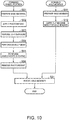
- Fig. 10 is a flowchart illustrating the manufacturing method of the escape wheel & pinion according to the embodiment.
- the manufacturing method of the escape wheel & pinion 35 serving as the mechanical component according to the embodiment includes a step (first step) of forming the wheel portion (escape wheel portion 101) serving as the rotary member, a step (second step) of forming the axle member 102, and a step (third step) of inserting the axle member 102 into the escape wheel portion 101 so as to form the escape wheel & pinion 35.
- the step of forming the escape wheel portion 101 as the first step is performed so as to form the holder 115 in the escape wheel portion 101, and includes Step S01 to Step S06.
- a wafer-shaped base material containing silicon is prepared (Step S01).
- a photoresist is applied to the front surface of the base material by means of spin coating or spray coating, for example (Step S02).
- the photoresist to be applied in Step S02 can employ either a negative type or a positive type material.
- Step S03 the photoresist applied onto the front surface of the base material is subjected to light exposure by using a photolithography technique
- Step S04 development is performed
- a photoresist pattern serving as a mask (etching mask) corresponding to a planar outer shape of the escape wheel portion 101 illustrated in Fig. 6 is formed.
- Step S05 the photoresist pattern formed in Step S03 and Step S04 is used as the mask, and anisotropic etching such as deep reactive ion etching (DRIE) is performed on the base material (Step S05).
- DRIE deep reactive ion etching
- the base material is deeply dug from the front surface side in a substantially vertical direction.
- an outer shape of the escape wheel portion 101 having the rim portion 111 having the plurality of the tooth portions 112, and the holder 115 having the first holder 113 and the second holder 114 is obtained.
- Step S06 the photoresist (photoresist pattern) is removed (Step S06 in Fig. 10 ) .
- the photoresist can be removed by means of wet etching using fuming nitric acid or organic solvent capable of dissolving and peeling off the photoresist, or by means of oxygen plasma ashing. In this manner, the step of forming the escape wheel portion 101 is completed.
- a mask may be formed so as to protect the rear surface of the base material from etching. Since the mask is formed on the rear surface of the base material, the base material is not etched from the rear surface side in Step S05. Accordingly, a shape of the side surface (surface along the axial direction) of the tooth portion 112 and the holder 115 is not changed. Therefore, it is possible to obtain a cross-sectional shape of the escape wheel portion 101 as illustrated in Fig. 4 .
- the silicon is used as the base material of the escape wheel portion 101. Accordingly, respective portions such as the first holder 113, the second holder 114, and the rim portion 111 of the escape wheel portion 101 can be formed using the same base material by performing the same etching step, and a plurality of the escape wheel portions 101 can be manufactured from the base material. Accordingly, it is possible to improve the productivity of the escape wheel portion 101 and to reduce the production cost.
- the escape wheel portion 101 is formed using the photolithography or etching technique. Therefore, the shape of respective portions can be formed into a desired shape, and the processing accuracy can be improved.
- the step of forming the axle member 102 as the second step is performed so as to form the recessed portion 127 and the escape pinion portion 122 in the axle member 102, and includes Step S11 and Step S12 illustrated in Fig. 10 .
- the step of forming the axle member 102 is performed separately from the step of forming the escape wheel portion 101 in Step S01 to Step S06.
- the axle member 102 desirably has sufficient rigidity and heat resistance as an axle body.
- Carbon steel is a material which is excellent in rigidity and heat resistance as described above, and further, is a material which allows high workability in carrying out cutting work and grinding work. Accordingly, the carbon steel is particularly suitable as the material for the axle member 102. Tantalum (Ta) or tungsten (W) may be used as the material of the axle member 102.
- the recessed portion 127 having the tapered portion 126 is formed by carrying out the cutting work to cut one round in the circumferential direction between the guide portion 123 and the escape pinion portion 122 in the axial direction, inward (toward the center side of the axle member 102) from the front surface of the axle member 102.
- the tapered portion 126 is formed so that the diameter decreases as the tapered portion 126 is closer to the escape pinion portion 122 from the guide portion 123 side of the recessed portion 127.
- the guide portion 123 is formed so that the diameter decreases as the guide portion 123 is farther away from the recessed portion 127 toward the tenon portion 121b side.
- the axle member 102 having the tenon portions 121a and 121b, the escape pinion portion 122, the guide portion 123, the recessed portion 127, the tapered portion 126, and the groove 125 is obtained.
- Step S21 the axle member 102 is inserted into the escape wheel portion 101 so as to fit the holder 115 into the recessed portion 127.
- Step S21 the escape wheel & pinion 35 is formed by inserting the axle member 102 formed in Step S11 and Step S12 into the escape wheel portion 101 formed in Step S01 to Step S06.
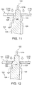
- Figs. 11 to 16 are schematic sectional views for describing the step of inserting the axle member into the escape wheel portion.
- Figs. 11 to 16 correspond to partial sectional views obtained by enlarging a main portion in Fig. 4 .
- a case is illustrated as an example of pressing the escape wheel portion 101 into the axle member 102.
- the axle member 102 may be inserted and pressed into the escape wheel portion 101.
- the escape wheel portion 101 is disposed on the tenon portion 121b side of the axle member 102. More specifically, the escape wheel portion 101 is disposed for the axle member 102 so that the tenon portion 121b projects from the escape wheel portion 101 through the inside of the through-hole configured to include the holder 115 (the first holder 113 and the second portion 114b of the second holder 114). In this case, the axle member 102 and the escape wheel portion 101 are disposed so that the first holder 113 and the groove 125 are located at the same position in the circumferential direction of the axle member 102 and the second portion 114b and the guide portion 123 are located at the same position (refer to Fig. 2 ).
- the escape wheel portion 101 is pressed into the axle member 102 along the axial direction until the second portion 114b of the second holder 114 comes into contact with the guide portion 123.
- the outer diameter D2 (refer to Fig. 8 ) of the axle member 102 in the end portion of the guide portion 123 on the tenon portion 121b side is equal to or smaller than the diameter D1 (refer to Fig.
- the gap G exists between the first holder 113 and the groove 125 (refer to Fig. 5 ). Accordingly, if the escape wheel portion 101 is pressed into the axle member 102, the first holder 113 is easily fitted into the groove 125.
- the escape wheel portion 101 is further pressed into the axle member 102.
- the axle member 102 is formed so that the diameter of the axle member 102 increases as the guide portion 123 is closer to the recessed portion 127 (tapered portion 126) from the tenon portion 121b side. Accordingly, the second portion 114b gradually spreads outward in the radial direction.
- the second portion 114b if the second portion 114b reaches the boundary portion 128 between the guide portion 123 and the recessed portion 127 (tapered portion 126), the second portion 114b is brought into a state where the second portion 114b spreads outward most in the radial direction. In this case, the stress acting outward in the radial direction which is applied to the second portion 114b from the axle member 102 is maximized.
- the outer diameter D3 (refer to Fig. 8 ) of the axle member 102 in the boundary portion 128 is equal to or smaller than the maximum diameter D1max of the inscribed circle 114c of the second portion 114b. Accordingly, the second portion 114b can cross the boundary portion 128.
- the second portion 114b comes into contact with the tapered portion 126 disposed in the recessed portion 127 on the guide portion 123 side.
- the second portion 114b attempts to return inward in the radial direction in a state where the second portion 114b spreads outward most in the radial direction when passing through the boundary portion 128.
- the axle member 102 is formed so that the diameter of the axle member 102 decreases as the tapered portion 126 is closer to the tooth 124 (hereinafter, simply referred to as the tooth 124) of the escape pinion portion 122 from the guide portion 123. Accordingly, as the second portion 114b returns inward in the radial direction, the second portion 114b moves to the tooth 124 side.
- the second portion 114b is fitted into the recessed portion 127 in a state of being in contact with the tooth 124.
- the diameter D1 (refer to Fig. 6 ) of the inscribed circle 114c of the second portion 114b of the escape wheel portion 101 formed in Step S01 to Step S06 is smaller than the outer diameter D4 (refer to Fig. 8 ) of the axle member 102 in the portion where the second portion 114b is in contact with the tapered portion 126 in a state where the axle member 102 is fitted into the recessed portion 127 in Step S21. Accordingly, even in a state where the axle member 102 is fitted into the recessed portion 127, the stress acting outward in the radial direction is applied to the second portion 114b.
- the stress acting toward the tooth 124 side in the axial direction is applied from the tapered portion 126 to each of the plurality of second portions 114b disposed in the circumferential direction, thereby pressing the holder 115 against the tooth 124.
- the escape wheel portion 101 can be held for the axle member 102 so that the front surface 101a and the rear surface 101b are orthogonal to the axis O1 (refer to Fig. 4 ).
- the diameter D5 (refer to Fig. 8 ) of the circumscribed circle of the tooth 124 is larger than the outer diameter D3 of the axle member 102 in the boundary portion 128, and is larger than the maximum diameter D1max of the inscribed circle 114c. Therefore, the tooth 124 regulates the position of the second portion 114b on the tenon portion 121a (refer to Fig. 4 ) side in the axial direction.
- the outer diameter D3 of the axle member 102 in the boundary portion 128 is larger than the outer diameter D4 of the axle member 102 in the portion where the second portion 114b is in contact with the tapered portion 126 in a state where the holder 115 is fitted into the recessed portion 127.
- the stress acting toward the tooth 124 side in the axial direction is applied from the tapered portion 126 to the second portion 114b. Therefore, the holder 115 is prevented from moving to the tenon portion 121b side. In this manner, it is possible to prevent the escape wheel portion 101 from falling out of the axle member 102. In other words, it is possible to prevent the axle member 102 from falling out of the escape wheel portion 101.
- the first holder 113 has the gap G between the groove 125 and the groove 125, thereby maintaining the state of being fitted into the groove 125.
- a step difference is formed between the groove 125 and the recessed portion 127 in the circumferential direction. Accordingly, the escape wheel portion 101 can be prevented from being rotated with respect to the axle member 102.
- the tapered portion 126 is not disposed in the recessed portion 127
- the second portion 114b does not enter the recessed portion 127. If the axial length of the recessed portion 127 is longer than the thickness of the second portion 114b, the second portion 114b and the recessed portion 127 are unsteadily fitted to each other.
- the tapered portion 126 is disposed in the recessed portion 127. Accordingly, even in a case where the axial length of the recessed portion 127 varies, the second portion 114b is fitted into the recessed portion 127 after coming into contact with any position of the tapered portions 126. Therefore, without disposing the stress relaxation layer in the escape wheel portion 101, the holder 115 is reliably fitted into the recessed portion 127, thereby enabling the escape wheel portion 101 and the axle member 102 to be fixed to each other. In this manner, it is possible to prevent an increase in manufacturing man-hours of the escape wheel & pinion 35 and a poor manufacturing yield of the escape wheel & pinion 35.
- the tapered portion 126 is disposed on the guide portion 123 side in the recessed portion 127.
- the invention is not limited thereto.
- the bottom portion of the recessed portion 127 may entirely be configured to include the tapered portion 126. According to this configuration, it is also possible to obtain an advantageous effect the same as that according to the above-described embodiment.
- the number of the holders 115 (the first holder 113 and the second holder 114) belonging to the escape wheel portion 101 is configured to be the same as the number (seven in the above-described embodiment) of the teeth 124 of the escape pinion portion 122.
- the invention is not limited thereto. According to the configuration in which the number of the holders 115 is smaller than the number of the teeth 124 (that is, the number of the grooves 125) of the escape pinion portion 122, it is also possible to obtain the advantageous effect the same as that according to the above-described embodiment.
- the second portion 114b faces the guide portion 123 in the circumferential direction of the axle member 102 and the first holder 113 is disposed at a position where the first holder 113 can be fitted into the groove 125.
- oxidation treatment for forming a silicon oxide film made of silicon dioxide (SiO 2 ) may be performed on the front surface of the escape wheel portion 101. If the oxidation treatment is performed on the escape wheel portion 101, the mechanical strength of the escape wheel portion 101 is improved by the silicon oxide film formed on the front surface of the escape wheel portion 101 made of the material containing silicon. In a case where the oxidation treatment is performed, it is preferable that thermal oxidation treatment is performed at high temperature of 1,000°C or higher, for example.
- the escape wheel & pinion 35 has been described as an example of the mechanical component.
- the invention is not limited thereto.
- the configuration and the manufacturing method of the mechanical component according to the invention are also applicable to other mechanical components such as the movement barrel 22, the center wheel & pinion 25, the third wheel & pinion 26, the second wheel & pinion 27, the pallet fork 36, and the balance with hairspring 40.
- the configuration and the manufacturing method of the mechanical component according to the invention are also applicable to other mechanical components in which the axle member does not have the projection portion (escape pinion portion 122 in the escape wheel & pinion 35 according to the above-described embodiment).
Landscapes
- Physics & Mathematics (AREA)
- General Physics & Mathematics (AREA)
- Engineering & Computer Science (AREA)
- General Engineering & Computer Science (AREA)
- Mechanical Engineering (AREA)
- Gears, Cams (AREA)
- Pressure Welding/Diffusion-Bonding (AREA)
Abstract
Description
- The present invention relates to a mechanical component, a timepiece, and a manufacturing method of a mechanical component.
- A mechanical timepiece is equipped with numerous mechanical components represented by wheels. The mechanical component such as the wheel is fixed (held) by inserting an axle member into a through-hole (holder) disposed at the center of a rotary member whose outer periphery has a plurality of teeth. In the related art, the mechanical component is formed by carrying out machine work for a metal material. However, in recent years, a base material containing silicon has been used as a material of the mechanical component for a timepiece. The mechanical component made of the silicon serving as the base material is lighter in weight than the mechanical component made of metal serving as the base material. Thus, an inertial force of the mechanical component can be reduced. Accordingly, improved efficiency in transferring energy is expected. The silicon allows various shapes to be freely formed using a photolithography and etching technique. Therefore, there is an advantage in that processing accuracy of the mechanical component can be improved by using the silicon as the base material.
-
JP-A-2012-167808 JP-A-2012-167808 - However, according to the mechanical component disclosed in
JP-A-2012-167808 - The axle member is formed by carrying out machine work such as cutting work and grinding work. Accordingly, in some cases, there are variations in a size of an outer diameter or an axial length of a portion of the axle member fitted into the through-hole of the rotary member, that is, a portion in contact with the stress relaxation layer. In contrast, the stress relaxation layer is the metal film. Accordingly, if the variations are significant when the machine work is carried out for the axle member, it is difficult to absorb the variations. For example, if the outer diameter of the axle member is small, the stress is insufficient when the rotary member and the axle member are fitted to each other, and the axle member consequently falls out of the rotary member. On the other hand, if the outer diameter of the axle member is large, the stress cannot be completely relaxed by the stress relaxation layer when the rotary member and the axle member are fitted to each other, and the rotary member is consequently damaged. Therefore, if the variations occur when the machine work is carried out for the axle member, there is a possibility that a manufacturing yield of the mechanical component may become poor.
- An advantage of some aspects of the invention is to solve at least a part of the problems described above, and the invention can be implemented as the following forms or application examples.
- A mechanical component according to this application example includes an axle member, and a rotary member that has a holder for holding the axle member, in which the axle member has a recessed portion to be fitted to the holder, and a first tapered portion inclined in an axial direction of the axle member is disposed in a portion where the recessed portion is in contact with the holder.
- According to the configuration of the mechanical component according to this application example, the axle member has the recessed portion to be fitted to the holder of the rotary member. The first tapered portion is disposed in the portion where the recessed portion is in contact with the holder. In a case where the first tapered portion is not disposed in the recessed portion, if an axial length of the recessed portion is shorter than a thickness of the holder, the holder does not enter the recessed portion. If the axial length of the recessed portion is longer than the thickness of the holder, the holder and the recessed portion are unsteadily fitted to each other. According to this application example, the first tapered portion inclined in the axial direction is disposed in the recessed portion. Accordingly, even in a case where the axial length of the recessed portion varies, the holder is fitted into the recessed portion by coming into contact with any position of the first tapered portion. Therefore, without disposing a stress relaxation layer in the rotary member, the holder is reliably fitted into the recessed portion, thereby enabling the rotary member and the axle member to be fixed to each other. In this manner, it is possible to prevent an increase in manufacturing man-hours of the mechanical component and a poor manufacturing yield of the mechanical component.
- In the mechanical component according to the application example, it is preferable that the first tapered portion is formed so that a diameter of the first tapered portion decreases as the first tapered portion is closer from one end side to the other end side in the recessed portion.
- According to the configuration of the mechanical component according to this application example, the first tapered portion is formed so that the diameter of the first tapered portion decreases as the first tapered portion is closer from one end side to the other end side in the recessed portion. Accordingly, a cross-sectional shape of the first tapered portion serves as an inclined surface facing the other end side in the axial direction. In this manner, stress acting from the first tapered portion toward the other end side is applied to the holder fitted into the recessed portion. Therefore, it is possible to prevent the axle member from falling out of the rotary member.
- In the mechanical component according to the application example, it is preferable that the axle member has a second tapered portion formed on a side opposite to the other end with respect to the recessed portion so that a diameter of the second tapered portion decreases as the second tapered portion is farther away from the recessed portion, and an inclination angle of the first tapered portion in the axial direction is larger than an inclination angle of the second tapered portion in the axial direction.
- According to the configuration of the mechanical component according to this application example, the axle member has the second tapered portion formed on the side opposite to the other end with respect to the recessed portion so that the diameter of the second tapered portion decreases as the second tapered portion is farther away from the recessed portion, that is, the diameter increases as the second tapered portion is closer to the recessed portion. Therefore, if the axle member is inserted into the rotary member from the side of the second tapered portion, the holder of the rotary member spreads outward as the holder is closer to the recessed portion in the second tapered portion. In this case, the inclination angle of the second tapered portion in the axial direction is smaller than the inclination angle of the first tapered portion. Accordingly, the stress applied to the holder gradually increases in a direction in which the axle member is inserted into the rotary member. Therefore, the axle member can be easily inserted into the rotary member. On the other hand, if the holder is fitted once into the recessed portion, the inclination angle of the first tapered portion in the axial direction is larger than the inclination angle of the second tapered portion. Accordingly, the stress applied to the holder rapidly increases in a direction in which the axle member falls out of the rotary member. Therefore, it is possible to prevent the axle member from falling out of the rotary member.
- In the mechanical component according to the application example, it is preferable that an outer diameter of the axle member in a boundary portion between the recessed portion and the second tapered portion is larger than an outer diameter of the axle member in a portion where the holder is in contact with the first tapered portion.
- According to the configuration of the mechanical component according to this application example, the outer diameter of the axle member in the boundary portion between the recessed portion having the first tapered portion and the second tapered portion is larger than the outer diameter of the portion where the holder is in contact with the first tapered portion. Accordingly, the holder fitted into the recessed portion is less likely to return to the second tapered portion side. Therefore, it is possible to prevent the axle member from falling out of the rotary member.
- In the mechanical component according to the application example, it is preferable that the axle member has a projection portion in contact with the holder, on the other end side of the recessed portion.
- According to the configuration of the mechanical component according to this application example, the holder of the rotary member is in contact with the first tapered portion disposed in the recessed portion, and is in contact with the projection portion disposed on the other end side of the recessed portion. Accordingly, the stress acting from the first tapered portion toward the projection portion is applied to the holder. Therefore, it is possible to effectively prevent the axle member from falling out of the rotary member.
- In the mechanical component according to the application example, it is preferable that the rotary member has a rim portion having a plurality of teeth, the holder has a first holder extending in a direction from the rim portion toward the axle member, and a second holder having a first portion extending in a direction intersecting the first holder and a second portion extending in the direction from the first portion toward the axle member, and the second portion is in contact with the first tapered portion.
- According to the configuration of the mechanical component according to this application example, the first portion extending in the direction intersecting the first holder is bent to the first holder extending in the direction from the rim portion toward the axle member. Accordingly, the second portion can be deformed in the direction in which the second portion faces the axle member, which is the extending direction of the second portion, and in the direction in which the second portion faces outward from the axle member. In this manner, even in a case where the outer diameter of the axle member in the recessed portion varies, the stress applied to the holder of the rotary member can be relaxed. Accordingly, damage to the rotary member can be prevented. The first portion is bent, and the second portion is deformed, thereby generating the stress. The stress enables the axle member to be located and held at the center of the rotary member.
- In the mechanical component according to the application example, it is preferable that the second holder has a plurality of the first portions.
- According to the configuration of the mechanical component according to this application example, the plurality of first portions connecting the first holder and the second portion to each other are likely to be bent in the direction from the rim portion toward the axle member in a plane configured to include the first holder and the second holder (the first portion and the second portion) . The plurality of first portions are provided in this way. Accordingly, even in a case where the outer diameter of the axle member in the recessed portion varies, it is possible to sufficiently obtain the stress for holding the axle member at the center of the rotary member. On the other hand, the plurality of first portions are less likely to be bent in the axial direction (longitudinal direction of the axle member) intersecting the plane configured to include the first holder and the second holder (the first portion and the second portion). Accordingly, the second portion is likely to be deformed in the direction toward the axle member and in the direction outward from the axle member. However, the second portion is less likely to be deformed in the axial direction. Therefore, the rotary member and the axle member can be reliably fixed to each other, and the rotary member can be prevented from being inclined from or falling out of the axle member.
- A timepiece according to this application example includes the mechanical component described above.
- According to the configuration of the timepiece according to this application example, the timepiece includes the mechanical component described above in any one of the application examples. Therefore, it is possible to provide a highly accurate timepiece which is excellent in quality and cost competitiveness.
- A manufacturing method of a mechanical component according to this application example includes forming a holder for holding an axle member in a rotary member, forming a recessed portion to be fitted to the holder in the axle member, and inserting the axle member into the rotary member so that the holder is fitted into the recessed portion, in which in the forming of the recessed portion, a first tapered portion is formed so that a diameter of the first tapered portion decreases as the first tapered portion is closer from one end side to the other end side in the recessed portion, and an inner diameter of the holder formed in the forming of the holder is smaller than an outer diameter of the axle member in a portion where the holder fitted into the recessed portion in fitting the holder into the recessed portion is in contact with the first tapered portion.
- According to the manufacturing method of a mechanical component according to this application example, in the forming of the recessed portion, the first tapered portion is formed in the recessed portion of the axle member. Accordingly, in a case where the axial length of the recessed portion varies, if the axle member is inserted into the rotary member in fitting the holder into the recessed portion, the holder is fitted into the recessed portion by coming into contact with any position of the first tapered portion. Accordingly, without disposing the stress relaxation layer in the rotary member, the holder is reliably fitted into the recessed portion, thereby enabling the rotary member and the axle member to be fixed to each other. In this manner, it is possible to prevent an increase in manufacturing man-hours of the mechanical component and a poor manufacturing yield of the mechanical component.
- The inner diameter of the holder formed in the forming of the holder is smaller than the outer diameter of the axle member in the portion where the holder fitted into the recessed portion in fitting the holder into the recessed portion is in contact with the first tapered portion. Accordingly, if the holder is fitted into the recessed portion, the stress spreading outward in the radial direction is applied from the first tapered portion to the holder. Then, the cross-sectional shape of the first tapered portion serves as the inclined surface which faces the other end side in the axial direction, for the holder fitting to the recessed portion. Therefore, the stress acting from the first tapered portion toward the other end side is applied to the holder fitted into the recessed portion. In this manner, it is possible to prevent the axle member from falling out of the rotary member.
- In the manufacturing method of a mechanical component according to the application example, it is preferable that in the forming of the recessed portion, a second tapered portion is formed on a side opposite to the other end with respect to the recessed portion so that a diameter of the second tapered portion decreases as the second tapered portion is farther away from the recessed portion, and an outer diameter of the axle member in a boundary portion between the recessed portion and the second tapered portion is larger than an outer diameter of the axle member in a portion where the holder fitted into the recessed portion in fitting the holder into the recessed portion is in contact with the first tapered portion.
- According to the manufacturing method of a mechanical component according to this application example, the axle member has the second tapered portion formed on the side opposite to the other end with respect to the recessed portion having the first tapered portion so that the diameter of the second tapered portion increases as the second tapered portion is closer to the recessed portion. Accordingly, if the axle member is inserted into the rotary member from the side of the second tapered portion, the holder spreads outward as the holder is closer to the recessed portion in the second tapered portion. Therefore, the axle member can be easily inserted into the rotary member. The outer diameter of the axle member in the boundary portion between the recessed portion and the second tapered portion is larger than the outer diameter of the axle member in the portion where the holder fitted into the recessed portion is in contact with the first tapered portion. Therefore, the holder fitted into the recessed portion having the first tapered portion after crossing the boundary portion from the second tapered portion is less likely to return to the second tapered portion side. In this manner, it is possible to prevent the axle member from falling out of the rotary member.
- The invention will be described with reference to the accompanying drawings, wherein like numbers reference like elements.
-
Fig. 1 is a plan view illustrating a front side of a movement of a mechanical timepiece according to the present embodiment. -
Fig. 2 is a plan view illustrating an escapement mechanism according to the embodiment. -
Fig. 3 is a perspective view when an escape wheel & pinion serving as a mechanical component according to the embodiment is viewed from a front surface side. -
Fig. 4 is a sectional view of the escape wheel & pinion which is taken along line A-A' inFig. 2 . -
Fig. 5 is a partial sectional view obtained by enlarging a C-portion illustrated inFig. 4 . -
Fig. 6 is a plan view illustrating an escape wheel portion serving as a rotary member according to the embodiment. -
Fig. 7 is a perspective view illustrating an axle member according to the embodiment. -
Fig. 8 is a sectional view of the axle member which is taken along line B-B' inFig. 2 . -
Fig. 9 is a partial sectional view for describing fitting between the escape wheel portion and the axle member. -
Fig. 10 is a flowchart illustrating a manufacturing method of the escape wheel & pinion according to the embodiment. -
Fig. 11 is a schematic sectional view for describing a step of inserting the axle member into the escape wheel portion. -
Fig. 12 is a schematic sectional view for describing a step of inserting the axle member into the escape wheel portion. -
Fig. 13 is a schematic sectional view for describing a step of inserting the axle member into the escape wheel portion. -
Fig. 14 is a schematic sectional view for describing a step of inserting the axle member into the escape wheel portion. -
Fig. 15 is a schematic sectional view for describing a step of inserting the axle member into the escape wheel portion. -
Fig. 16 is a schematic sectional view for describing a step of inserting the axle member into the escape wheel portion. - Hereinafter, an embodiment according to the invention will be described with reference to the drawings. In the embodiment, a mechanical timepiece will be treated as an example of a timepiece according to the invention. As an example of a mechanical component according to the invention, an escape wheel & pinion serving as one of wheels configuring timepiece components in a movement of the mechanical timepiece will be described as an example. In respective drawings below, in order to allow each layer or each member to have a recognizable size to some extent, in some cases, each layer or each member is illustrated using scales different from actual scales.
- First, a
mechanical timepiece 1 serving as the timepiece according to the embodiment will be described.Fig. 1 is a plan view illustrating a front side of the movement of the mechanical timepiece according to the embodiment. As illustrated inFig. 1 , themechanical timepiece 1 according to the embodiment is configured to include amovement 10 and a casing (not illustrated) for accommodating themovement 10. - A side outward of a paper surface in
Fig. 1 is referred to as a front side, and a side inward thereof is referred to as a rear side. Themovement 10 has amain plate 11 configuring a substrate. A dial (not illustrated) is located on the rear side of themain plate 11. A wheel train incorporated on the front side of themovement 10 is referred to as a front train wheel, and a wheel train incorporated on the rear side of themovement 10 is referred to as a rear wheel train. - The
main plate 11 has a windingstem guide hole 11a formed therein, and a windingstem 12 is rotatably incorporated in the windingstem guide hole 11a. The windingstem 12 is determined to have an axial position by a switching device having a settinglever 13, ayoke 14, ayoke spring 15, and a settinglever jumper 16. A windingpinion 17 is rotatably disposed in a guide axle portion of the windingstem 12. - Based on this configuration, if the winding
stem 12 is rotated in a state where the windingstem 12 is located at a first winding stem position (0-th stage) closest to an inner side of themovement 10 along a rotation axis direction, the windingpinion 17 is rotated via rotation of a clutch wheel (not illustrated). Thereafter, the windingpinion 17 is rotated, thereby rotating acrown wheel 20 meshing with the windingpinion 17. Thereafter, thecrown wheel 20 is rotated, thereby rotating aratchet wheel 21 meshing with thecrown wheel 20. Furthermore, theratchet wheel 21 is rotated, thereby winding a mainspring (power source) (not illustrated) accommodated in amovement barrel 22. - In addition to the above-described movement barrel (mechanical component) 22, the front train wheel of the
movement 10 is configured to include a center wheel & pinion (mechanical component) 25, a third wheel & pinion (mechanical component) 26, and a second wheel & pinion (mechanical component) 27 which are so-called wheels & pinions, and has a function to transmit a rotational force of themovement barrel 22. Anescapement mechanism 30 and aspeed control mechanism 31 for controlling the rotation of the front train wheel are arranged on the front side of themovement 10. - The center wheel &
pinion 25 meshes with themovement barrel 22. The third wheel &pinion 26 meshes with the center wheel &pinion 25. The second wheel &pinion 27 meshes with the third wheel &pinion 26. Theescapement mechanism 30 controls the rotation of the above-described front train wheel, and includes an escape wheel & pinion (mechanical component) 35 meshing with the second wheel &pinion 27 and a pallet fork (mechanical component) 36 which causes the escape wheel &pinion 35 to escape so as to be regularly rotated. Thespeed control mechanism 31 controls speed of the above-describedescapement mechanism 30, and includes a balance with hairspring (mechanical component) 40. - Next, the escape wheel &
pinion 35 included in theescapement mechanism 30 according to the embodiment will be described in more detail.Fig. 2 is a plan view of the escapement mechanism according to the embodiment.Fig. 3 is a perspective view when the escape wheel & pinion serving as the mechanical component according to the embodiment is viewed from the front surface side.Fig. 4 is a sectional view of the escape wheel & pinion which is taken along line A-A' inFig. 2 .Fig. 5 is a partial sectional view obtained by enlarging a C-portion illustrated inFig. 4 .Fig. 6 is a plan view of the escape wheel portion serving as a rotary member according to the embodiment.Fig. 7 is a perspective view of an axle member according to the embodiment.Fig. 8 is a sectional view of the axle member which is taken along line B-B' inFig. 2 .Fig. 9 is a partial sectional view for describing fitting between the escape wheel portion and the axle member. - As illustrated in
Figs. 2 and3 , the escape wheel &pinion 35 included in theescapement mechanism 30 includes anescape wheel portion 101 as a rotary member and an axle member (rotary axle) 102 coaxially (axis O1) fixed to theescape wheel portion 101. - In the following description, a longitudinal direction along the axis O1 of the
escape wheel portion 101 and theaxle member 102 is simply referred to as an axial direction. Afront surface 101a and arear surface 101b of theescape wheel portion 101 are orthogonal to the axis O1 (line passing the center of theaxle member 102 along the axial direction) . A direction passing through the axis O1 in a plane parallel to thefront surface 101a and therear surface 101b of theescape wheel portion 101 is referred to as a radial direction. A direction in which theescape wheel portion 101 and theaxle member 102 turn around the axis O1 is referred to as a circumferential direction. - In the
escape wheel portion 101, thefront surface 101a and therear surface 101b (refer toFig. 3 ) have a plate shape which is formed into a flat surface and has a uniform thickness over the entire surface. Theescape wheel portion 101 is made of a material having a crystal orientation such as single crystal silicon, or a metal material. - The
escape wheel portion 101 has arim portion 111 having a plurality oftooth portions 112 and aholder 115 for holding theaxle member 102. Therim portion 111 is the annular portion of an outer edge of theescape wheel portion 101. Thetooth portion 112 protrudes outward from an outer periphery of therim portion 111, and is formed in a special hook shape. Thepallets tooth portions 112. - The
holder 115 is located on theaxle member 102 side with respect to therim portion 111. In the embodiment, theescape wheel portion 101 has sevenholders 115. Theholders 115 are located at seven positions at an equal pitch of 360°/7 in the circumferential direction of theannular rim portion 111. The number of theholders 115 may be in a range of three to seven, or may be seven or more, and is not particularly limited. - The
holder 115 has afirst holder 113 extending from therim portion 111 and asecond holder 114 branched from thefirst holder 113. Thefirst holder 113, the second holder 114 (first portion 114a andsecond portion 114b), and therim portion 111 are integrally formed of the same material. - The
axle member 102 is inserted into a region surrounded by the holders 115 (first holder 113 and second holder 114) of a central portion of theescape wheel portion 101. In other words, a through-hole through which theaxle member 102 is inserted into the central portion of theescape wheel portion 101 is configured to include the holder 115 (first holder 113 and second holder 114). - The
first holder 113 extends in a direction from therim portion 111 toward theaxle member 102. Thefirst holder 113 has a function to prevent the rotation of theescape wheel portion 101 with respect to theaxle member 102 by being fitted into agroove 125 of theaxle member 102. The tip of thefirst holder 113 is located on a center side of theaxle member 102 from the tip of thesecond portion 114b of the second holder 114 (refer toFig. 6 ). - The
second holder 114 has thefirst portion 114a and thesecond portion 114b. Thesecond holder 114 has a function to fix theaxle member 102 to the center of theescape wheel portion 101 and to prevent theescape wheel portion 101 from being inclined from or falling out of theaxle member 102. - The
first portion 114a is connected to thefirst holder 113, is branched from thefirst holder 113, and extends in a direction intersecting the extending direction of thefirst holder 113. Thesecond holder 114 has a plurality of thefirst portions 114a. The plurality offirst portions 114a are arranged substantially parallel to each other. Thesecond portion 114b is connected to the plurality offirst portions 114a, and extends in a direction toward theaxle member 102. The plurality offirst portions 114a have a function to relax the stress applied to thesecond portion 114b in the extending direction of thesecond portion 114b. - The
second portion 114b is fitted into the recessedportion 127 of the axle member 102 (refer toFigs. 4 and5 ). An inscribed circle in contact with the tip of thesecond portion 114b will be referred to as an inscribedcircle 114c (refer toFig. 6 ). In a state where thesecond portion 114b is not fitted into the recessed portion 127 (state where theaxle member 102 is not inserted into the escape wheel portion 101), that is, in a state where the stress is not applied to thesecond holder 114, a diameter of the inscribedcircle 114c set to D1. The diameter D1 of the inscribedcircle 114c is also called an inner diameter of thesecond holder 114. Thefirst holder 113 extends inward of the inscribedcircle 114c. - If the
escape wheel portion 101 is viewed from theaxle member 102, thefirst holder 113 and thesecond portion 114b respectively and radially extend outward in the radial direction. In a plane parallel to thefront surface 101a of theescape wheel portion 101, the extending direction of thefirst holder 113 and the extending direction of thesecond portion 114b are respectively directions along the radial direction, but are not parallel to each other. The extending direction of thefirst portion 114a is a direction intersecting the extending direction of thefirst holder 113 and the extending direction of thesecond portion 114b in a plane parallel to thefront surface 101a of theescape wheel portion 101. - The plurality of
first portions 114a formed in a beam shape between thefirst holder 113 and thesecond portion 114b are less likely to be bent in the extending direction, in a plane (thefront surface 101a of theescape wheel portion 101 and therear surface 101b) configured to include the plurality offirst portions 114a, but are likely to be bent in the direction intersecting the extending direction. The plurality offirst portions 114a are less likely to be bent in the axial direction intersecting the plane configured to include the plurality offirst portions 114a. - If the plurality of
first portions 114a are bent and deformed outward in the extending direction of thesecond portion 114b, the inner diameter of thesecond holder 114, that is, the diameter of the inscribedcircle 114c (refer toFig. 6 ) in contact with the tip of thesecond portion 114b becomes larger than the diameter D1. Therefore, when theaxle member 102 is inserted into theescape wheel portion 101, the plurality offirst portions 114a are bent corresponding to the outer diameter of theaxle member 102, and are deformed in the extending direction of thesecond portion 114b with respect to theaxle member 102. In this manner, thesecond portion 114b can be easily fitted into the recessedportion 127. The maximum diameter of the inscribedcircle 114c where the plurality offirst portions 114a can be bent and deformed is set to D1max. - When an external force is applied to the escape wheel &
pinion 35, the plurality offirst portions 114a are likely to be deformed in extending direction of thesecond portion 114b. Accordingly, theaxle member 102 can be held at the center of theescape wheel portion 101. Since the plurality offirst portions 114a are bent, it is possible to relax the external force applied to the escape wheel &pinion 35. Accordingly, damage to theescape wheel portion 101 can be prevented. On the other hand, the plurality offirst portions 114a are less likely to be deformed in the axial direction, that is, in the direction where theaxle member 102 falls out of theescape wheel portion 101. Therefore, theescape wheel portion 101 and theaxle member 102 can be reliably fixed to each other, and theescape wheel portion 101 can be prevented from being inclined from or falling out of theaxle member 102. - The plurality of the
tooth portions 112 of the escape wheel & pinion 35 (escape wheel portion 101) are adapted to mesh with thepallet fork 36. Thepallet fork 36 includes apallet fork body 142d formed into a T-shape by three pallet fork beams 143 and apallet staff 142f serving as an axle. Thepallet fork body 142d is configured to be pivotable by thepallet staff 142f. Both ends of thepallet staff 142f are respectively supported so as to be pivotable with respect to the main plate 11 (refer toFig. 1 ) and a pallet bridge (not illustrated). - In the three pallet fork beams 143,
pallets guard pin 145 is attached to the tip of the remainingpallet fork beam 143 . Thepallets pallet fork beam 143 by using an adhesive. - When the
pallet fork 36 configured in this way pivots around thepallet staff 142f, thepallet 144a or thepallet 144b comes into contact with the tip of thetooth portion 112 of the escape wheel &pinion 35. In this case, thepallet fork beam 143 to which theguard pin 145 is attached comes into contact with a banking pin (not illustrated) so that thepallet fork 36 does not further pivot in the same direction. As a result, the rotation of the escape wheel &pinion 35 is temporarily stopped. - As illustrated in
Fig. 2 , in a plan view when viewed in the axial direction of theaxle member 102, theaxle member 102 is located in the central portion of theescape wheel portion 101. As illustrated inFigs. 3 and4 , theaxle member 102 is inserted from therear surface 101b side into the through-hole surrounded by theholder 115 of theescape wheel portion 101. Theaxle member 102 has a recessed portion 127 (refer toFig. 4 ) fitted to theholder 115. The holder 115 (thesecond portion 114b of the second holder 114) of theescape wheel portion 101 is fitted into the recessedportion 127 of theaxle member 102. In this manner, theaxle member 102 is fixed to theescape wheel portion 101. - The
axle member 102 is made of carbon steel which is excellent in rigidity and heat resistance and which allows high workability in carrying out cutting work and grinding work. A material of theaxle member 102 may be tantalum (Ta) or tungsten (W). Theaxle member 102 hastenon portions escape pinion portion 122 serving as a projection portion, the recessedportion 127, a taperedportion 126 serving as a first tapered portion, and aguide portion 123 serving as a second tapered portion. - The
tenon portions axle member 102 in the axial direction. In thetenon portions tenon portion 121a located on therear surface 101b side of theescape wheel portion 101 is rotatably supported by a train wheel bridge (not illustrated), and thetenon portion 121b located on thefront surface 101a side of theescape wheel portion 101 is rotatably supported by themain plate 11. - The
escape pinion portion 122 is disposed on therear surface 101b side of theescape wheel portion 101. Theescape pinion portion 122 is formed on thetenon portion 121a side with respect to the recessedportion 127 along the axial direction of theaxle member 102. In theescape pinion portion 122, a portion on theescape wheel portion 101 side has a function as a projection portion, and a portion on thetenon portion 121a side has a function as the wheel portion. The portion of theescape pinion portion 122 on thetenon portion 121a side meshes with the wheel portion of the second wheel & pinion 27 (refer toFig. 1 ) . In this manner, a rotational force of the second wheel &pinion 27 is transmitted to theaxle member 102, and the escape wheel &pinion 35 is rotated. - The
escape pinion portion 122 has the plurality ofteeth 124. The plurality ofteeth 124 extend along the axial direction of theaxle member 102, and are formed so as to protrude outward in the radial direction. An end portion of the plurality ofteeth 124 on thetenon portion 121b side is in contact with therear surface 101b of the holder 115 (second portion 114b) of theescape wheel portion 101. Agroove 125 is formed along the axial direction between the plurality ofteeth 124 in the circumferential direction. Thegroove 125 extends from theescape pinion portion 122 through the recessedportion 127 to theguide portion 123 along the axial direction (refer toFig. 7 ). - In the embodiment, the
escape pinion portion 122 has seventeeth 124. Theteeth 124 are respectively arranged at seven positions at an equal pitch of 360°/7 in the circumferential direction of theescape pinion portion 122. Therefore, thegrooves 125 are also respectively arranged at seven positions at an equal pitch of 360°/7 in the circumferential direction of theescape pinion portion 122. Although the number of theteeth 124 and thegrooves 125 is seven in the embodiment, the number may be in a range of three to seven, or seven or more, and is not particularly limited. - The
guide portion 123 serving as the second tapered portion is disposed on thefront surface 101a side of theescape wheel portion 101. Theguide portion 123 is formed on thetenon portion 121b side opposite to theescape pinion portion 122 with respect to the recessedportion 127. Theguide portion 123 is formed to have the diameter larger than that of thetenon portions guide portion 123 has a function to guide thesecond portion 114b of theholder 115 when theaxle member 102 is inserted into theescape wheel portion 101. - The
guide portion 123 is formed so that the diameter decreases as theguide portion 123 is farther away from the recessedportion 127 to thetenon portion 121b side. In other words, theguide portion 123 is formed so that the diameter increases as theguide portion 123 is closer to the recessedportion 127 fitted to theholder 115 of theescape wheel portion 101 from thetenon portion 121b side inserted into theescape wheel portion 101. Theguide portion 123 is divided by thegroove 125 in the circumferential direction. Therefore, theguide portions 123 are respectively arranged at seven positions at an equal pitch of 360°/7 in the circumferential direction on thetenon portion 121b side of theaxle member 102. Theguide portions 123 and theteeth 124 are disposed at the same position in the circumferential direction of theaxle member 102. - A cross section of the escape wheel &
pinion 35 illustrated inFigs. 4 and5 is taken along line A-A' inFig. 2 . That is, the left side inFigs. 4 and5 is a cross section passing through theguide portion 123 of theaxle member 102 and thetooth 124 of theescape pinion portion 122, and the right side is a cross section passing through thegroove 125 of theaxle member 102. - As illustrated in
Figs. 4 and5 , thegroove 125 is linearly disposed along the axial direction from theescape pinion portion 122 throughout theguide portion 123. Thegroove 125 is formed so as to be recessed inward of thetooth 124, the recessedportion 127, and theguide portion 123 of theescape pinion portion 122 in the radial direction (refer toFig. 7 ). Thegroove 125 has a function to prevent the rotation of theescape wheel portion 101 with respect to theaxle member 102 by being fitted to thefirst holder 113. - As illustrated in
Fig. 5 , thefirst holder 113 is fitted into thegroove 125 at a position where the recessedportion 127 is disposed in the axial direction (upward-downward direction inFig. 5 ). In a state where thefirst holder 113 is fitted into thegroove 125, a gap G is designed to exist between thefirst holder 113 and thegroove 125. In this state, the stress is not generated between theaxle member 102 and thefirst holder 113. However, when an external force is applied to the escape wheel &pinion 35 in a state where the mechanical timepiece 1 (movement 10) having the escape wheel &pinion 35 incorporated therein is operated, thefirst holder 113 may come into contact with theaxle member 102. - As illustrated in
Fig. 7 , thegroove 125 is disposed so as to be recessed from the recessedportion 127, thereby forming a step difference between thegroove 125 and the recessedportion 127 in the circumferential direction. In thegroove 125, the tip of thefirst holder 113 is located on the center side of theaxle member 102 from the recessed portion 127 (refer toFig. 4 ). Therefore, even if the external force is applied to the circumferential direction which is the rotation direction of the escape wheel &pinion 35, a state where thefirst holder 113 is fitted into thegroove 125 is held. In this manner, theescape wheel portion 101 can be prevented from being rotated with respect to theaxle member 102. - The
groove 125 is disposed from theguide portion 123 throughout theescape pinion portion 122. Accordingly, when theaxle member 102 is inserted into theescape wheel portion 101 from thetenon portion 121b side, if the position of thefirst holder 113 is aligned with the position of thegroove 125, theaxle member 102 can be inserted into theescape wheel portion 101 in a state where thefirst holder 113 is fitted into the groove 125 (refer toFig. 4 ). - The recessed
portion 127 is disposed between theguide portion 123 and theescape pinion portion 122 in the axial direction. In other words, theaxle member 102 has theguide portion 123 on one end side (tenon portion 121b side) of the recessedportion 127, and the escape pinion portion 122 (tooth 124) on the other end side (tenon portion 121a side) of the recessedportion 127. The recessedportion 127 is disposed to turn around the axis O1 (refer toFig. 4 ) of theaxle member 102. - A cross section of the escape wheel &
pinion 35 illustrated inFig. 8 is taken along line B-B' inFig. 2 , and is laterally symmetrical. That is, both the left side and right side inFig. 8 are cross sections passing through theguide portion 123 of theaxle member 102 and thetooth 124 of theescape pinion portion 122. - As illustrated in
Fig. 8 , the recessedportion 127 is formed so as to be recessed inward (toward the center side of the axle member 102) of thetooth 124 and theguide portion 123 of theescape pinion portion 122 in the radial direction. The recessedportion 127 has a function to prevent theaxle member 102 from falling out of theescape wheel portion 101 by being fitted to thesecond portion 114b of theholder 115. - The recessed
portion 127 has the taperedportion 126 serving as the first tapered portion. The taperedportion 126 is disposed on one end side (tenon portion 121b side) in the recessedportion 127. The taperedportion 126 is in contact with thesecond portion 114b. In other words, the taperedportion 126 is disposed in a portion in contact with the holder 115 (second portion 114b) of the recessedportion 127. Thesecond portion 114b is not in contact with the bottom portion of the recessedportion 127 since thesecond portion 114b is fitted into the recessedportion 127 in contact with the taperedportion 126. - The tapered
portion 126 is formed so that the diameter decreases as the taperedportion 126 is closer to theescape pinion portion 122 from theguide portion 123 side in the axial direction. Therefore, the outer diameter of theaxle member 102 from thetenon portion 121b to the other end side (tenon portion 121a side) of the recessedportion 127 increases toward aboundary portion 128 between thetapered portion 126 and theguide portion 123 from thetenon portion 121b side. After reaching theboundary portion 128, the outer diameter of theaxle member 102 decreases as theaxle member 102 is closer to theescape pinion portion 122 in the taperedportion 126. - The
boundary portion 128 is located between thetapered portion 126 and theguide portion 123 in theaxle member 102. For example, in a case where a cross-sectional shape of the portion extending from the taperedportion 126 throughout theguide portion 123 in theaxle member 102 is a triangular shape having the taperedportion 126 and theguide portion 123 as a hypotenuse, an apex of the triangular shape is set as theboundary portion 128. In a case where the cross-sectional shape is a trapezoidal shape having the taperedportion 126 and theguide portion 123 as the hypotenuse, a top bottom of the trapezoidal shape is set as theboundary portion 128. - The tapered
portion 126 inclined in the axial direction is disposed in the recessedportion 127. Accordingly, even if the axial length of the recessedportion 127 varies, the holder 115 (second portion 114b) is fitted into the recessedportion 127 by coming into contact with any position of the taperedportion 126. That is, the taperedportion 126 can absorb the variations in the axial length of the recessedportion 127. Therefore, without disposing the stress relaxation layer in theescape wheel portion 101, theholder 115 is reliably fitted into the recessedportion 127, thereby enabling theescape wheel portion 101 and theaxle member 102 to be fixed to each other. - Here, an outer diameter D2 of the
axle member 102 in an end portion of theguide portion 123 on thetenon portion 121b side is preferably equal to or smaller than the inner diameter of thesecond holder 114 in a state where theaxle member 102 is not inserted into theescape wheel portion 101, that is, the diameter D1 (refer toFig. 6 ) of the inscribedcircle 114c of thesecond portion 114b. If the outer diameter D2 of theaxle member 102 is equal to or smaller than the diameter D1 of the inscribedcircle 114c of thesecond portion 114b, when theaxle member 102 is inserted into theescape wheel portion 101 from thetenon portion 121b side, theaxle member 102 can be easily inserted into the inscribedcircle 114c of thesecond portion 114b. - An outer diameter D4 of the
axle member 102 in a portion where thesecond portion 114b is in contact with the taperedportion 126 in a state where theholder 115 is fitted to the recessedportion 127 is larger than the outer diameter D1 of the inscribedcircle 114c of thesecond portion 114b in a state where theaxle member 102 is not inserted. An outer diameter D3 of theaxle member 102 in theboundary portion 128 is larger than the diameter D1 of the inscribedcircle 114c of thesecond portion 114b. The outer diameter D3 of theaxle member 102 in theboundary portion 128 is larger than the outer diameter D4 of theaxle member 102 in a portion where thesecond portion 114b is in contact with the taperedportion 126 in a state where theholder 115 is fitted into the recessedportion 127. - Therefore, in a state where the
holder 115 is fitted into the recessedportion 127, if thesecond portion 114b attempts to move in a direction where thesecond portion 114b is shifted relative to theguide portion 123 side with respect to theaxle member 102, that is, in a direction where theaxle member 102 falls out of theescape wheel portion 101, the stress applied to thesecond portion 114b increases toward theboundary portion 128. In this manner, theaxle member 102 is prevented from falling out of theescape wheel portion 101. - However, the outer diameter D3 of the
axle member 102 in theboundary portion 128 is set to be equal to or smaller than a maximum diameter D1max of the inscribedcircle 114c in which the plurality offirst portions 114a (refer toFig. 6 ) can be bent and deformed outward in the extending direction of thesecond portion 114b. If the outer diameter D3 of theaxle member 102 in theboundary portion 128 exceeds the maximum diameter D1max of the inscribedcircle 114c, thesecond portion 114b cannot be fitted into the recessedportion 127 after crossing theboundary portion 128 from theguide portion 123. - Furthermore, a diameter D5 of a circumscribed circle of the
tooth 124 of theescape pinion portion 122 is larger than the outer diameter D3 of theaxle member 102 in theboundary portion 128, and is larger than the maximum diameter D1max of the inscribedcircle 114c. In this manner, even if the plurality offirst portions 114a are bent and thesecond portion 114b is moved outward to the maximum in the radial direction, thesecond portion 114b does not cross thetooth 124 of theescape pinion portion 122. That is, thetooth 124 of theescape pinion portion 122 regulates a position of theholder 115 on thetenon portion 121a (refer toFig. 4 ) side in the axial direction. -
Fig. 9 is a partial sectional view obtained by enlarging the left side portion inFig. 8 . InFig. 9 , a position of the tip of thesecond portion 114b in a state where theaxle member 102 is not inserted is illustrated by a two-dot chain line. In other words, the position of the tip of thesecond portion 114b when the diameter of the inscribedcircle 114c of thesecond portion 114b is set to D1 is illustrated by the two-dot chain line. The position of the tip of thesecond portion 114b in a state where theholder 115 is fitted into the recessedportion 127 is illustrated by a solid line. In the state where theholder 115 is fitted into the recessedportion 127, the diameter of the inscribedcircle 114c of thesecond portion 114b is the same as the outer diameter D4 of theaxle member 102. In a case where a corner portion of thesecond portion 114b is rounded or is formed into a tapered shape, the diameter of the inscribedcircle 114c of thesecond portion 114b becomes smaller than the outer diameter D4 of theaxle member 102. - As illustrated in
Fig. 9 , in a state where theaxle member 102 is inserted and theholder 115 is fitted into the recessedportion 127, compared to a state where theaxle member 102 is not inserted, thesecond portion 114b spread outward in the radial direction. In this manner, the stress acting outward in the radial direction is applied to thesecond portion 114b. Accordingly, theholder 115 can hold a state of being fitted into the recessedportion 127. - A distance in the radial direction between the position of the tip of the
second portion 114b and theboundary portion 128 in a state where theholder 115 is fitted into the recessedportion 127 is set to D6. The distance D6 is half of a difference between the outer diameter D3 of theaxle member 102 in theboundary portion 128 and the outer diameter D4 of theaxle member 102 in the portion where thesecond portion 114b is in contact with the taperedportion 126, that is, D6=(D3-D4)/2. The distance D6 is preferably set to approximately 10 µm. If the distance D6 is small, in a case where the external force is applied so as to spread thesecond portion 114b outward in the radial direction, there is a possibility that thesecond portion 114b may be shifted to theguide portion 123 side after crossing theboundary portion 128 . - The cross-sectional shape of the tapered
portion 126 serves as the inclined surface which faces outward in the radial direction of theaxle member 102 and theescape pinion portion 122 side in the axial direction. On the other hand, the cross-sectional shape of theguide portion 123 serves as the inclined surface which faces outward in the radial direction of theaxle member 102 and thetenon portion 121b side in the axial direction. An inclination angle of the taperedportion 126 in the axial direction is set to θ1, and an inclination angle of theguide portion 123 in the axial direction is set to θ2. The inclination angle θ1 of the taperedportion 126 in the axial direction is larger than the inclination angle θ2 in the axial direction of theguide portion 123. - The inclination angle θ1 in the axial direction of the tapered
portion 126 is larger than the inclination angle θ2 in the axial direction of theguide portion 123. Accordingly, the stress applied to thesecond portion 114b rapidly increases in the direction where theholder 115 moves from the taperedportion 126 toward theguide portion 123, that is, in the direction where theaxle member 102 falls out of theescape wheel portion 101. In this manner, theaxle member 102 is prevented from falling out of theescape wheel portion 101. - On the other hand, since the inclination angle θ2 in the axial direction of the
guide portion 123 is smaller than the inclination angle θ1 in the axial direction of the taperedportion 126. Accordingly, when theaxle member 102 is inserted into theescape wheel portion 101 from thetenon portion 121b side, the stress applied to thesecond portion 114b in theguide portion 123 gradually increases. In this manner, thesecond portion 114b gradually spreads outward in the radial direction. Therefore, theaxle member 102 can be easily inserted into theescape wheel portion 101. - The inclination angle θ1 in the axial direction of the tapered
portion 126 is preferably approximately 45°. If the inclination angle θ1 of the taperedportion 126 is approximately 45°, the stress acting outward in the radial direction and the stress acting toward the escape pinion portion 122 (tooth 124) side in the axial direction are applied from the taperedportion 126 to the holder 115 (second portion 114b) in a balanced manner. - As described above, the stress acting outward in the radial direction is applied to the
second portion 114b. In this manner, theholder 115 can hold a state of being fitted into the recessedportion 127. The stress acting toward theescape pinion portion 122 side in the axial direction is applied to thesecond portion 114b. In this manner, thesecond portion 114b is pressed against thetooth 124 of theescape pinion portion 122. In this manner, theaxle member 102 can be effectively prevented from falling out of theescape wheel portion 101. Thesecond portion 114b is pressed against thetooth 124 of theescape pinion portion 122. In this manner, theescape wheel portion 101 can be held for theaxle member 102 so that thefront surface 101a and therear surface 101b are orthogonal to the axis O1. - If the inclination angle θ1 of the tapered
portion 126 is small, the stress acting toward theescape pinion portion 122 side which is applied to thesecond portion 114b from the taperedportion 126 decreases. Accordingly, an advantageous effect is reduced in preventing theaxle member 102 from falling out of theescape wheel portion 101. If the inclination angle θ1 of the taperedportion 126 is large, the axial length of the taperedportion 126 decreases. Accordingly, a width of variations which can be absorbed by the taperedportion 126 decreases. - Next, a manufacturing method of the escape wheel &
pinion 35 serving as the mechanical component according to the embodiment will be described.Fig. 10 is a flowchart illustrating the manufacturing method of the escape wheel & pinion according to the embodiment. As illustrated inFig. 10 , the manufacturing method of the escape wheel &pinion 35 serving as the mechanical component according to the embodiment includes a step (first step) of forming the wheel portion (escape wheel portion 101) serving as the rotary member, a step (second step) of forming theaxle member 102, and a step (third step) of inserting theaxle member 102 into theescape wheel portion 101 so as to form the escape wheel &pinion 35. - The step of forming the
escape wheel portion 101 as the first step is performed so as to form theholder 115 in theescape wheel portion 101, and includes Step S01 to Step S06. First, a wafer-shaped base material containing silicon is prepared (Step S01). Subsequently, a photoresist is applied to the front surface of the base material by means of spin coating or spray coating, for example (Step S02). The photoresist to be applied in Step S02 can employ either a negative type or a positive type material. - Subsequently, the photoresist applied onto the front surface of the base material is subjected to light exposure by using a photolithography technique (Step S03) and development is performed (Step S04). In this manner, a photoresist pattern serving as a mask (etching mask) corresponding to a planar outer shape of the
escape wheel portion 101 illustrated inFig. 6 is formed. - Subsequently, the photoresist pattern formed in Step S03 and Step S04 is used as the mask, and anisotropic etching such as deep reactive ion etching (DRIE) is performed on the base material (Step S05). In this manner, through the photoresist pattern, the base material is deeply dug from the front surface side in a substantially vertical direction. As illustrated in
Fig. 6 , an outer shape of theescape wheel portion 101 having therim portion 111 having the plurality of thetooth portions 112, and theholder 115 having thefirst holder 113 and thesecond holder 114 is obtained. - Subsequently, the photoresist (photoresist pattern) is removed (Step S06 in
Fig. 10 ) . In Step S06, for example, the photoresist can be removed by means of wet etching using fuming nitric acid or organic solvent capable of dissolving and peeling off the photoresist, or by means of oxygen plasma ashing. In this manner, the step of forming theescape wheel portion 101 is completed. - When the anisotropic etching is performed on the base material in Step S05, a mask may be formed so as to protect the rear surface of the base material from etching. Since the mask is formed on the rear surface of the base material, the base material is not etched from the rear surface side in Step S05. Accordingly, a shape of the side surface (surface along the axial direction) of the
tooth portion 112 and theholder 115 is not changed. Therefore, it is possible to obtain a cross-sectional shape of theescape wheel portion 101 as illustrated inFig. 4 . - The silicon is used as the base material of the
escape wheel portion 101. Accordingly, respective portions such as thefirst holder 113, thesecond holder 114, and therim portion 111 of theescape wheel portion 101 can be formed using the same base material by performing the same etching step, and a plurality of theescape wheel portions 101 can be manufactured from the base material. Accordingly, it is possible to improve the productivity of theescape wheel portion 101 and to reduce the production cost. Theescape wheel portion 101 is formed using the photolithography or etching technique. Therefore, the shape of respective portions can be formed into a desired shape, and the processing accuracy can be improved. - The step of forming the
axle member 102 as the second step is performed so as to form the recessedportion 127 and theescape pinion portion 122 in theaxle member 102, and includes Step S11 and Step S12 illustrated inFig. 10 . The step of forming theaxle member 102 is performed separately from the step of forming theescape wheel portion 101 in Step S01 to Step S06. - First, a member serving as the
axle member 102 is prepared (Step S11). Theaxle member 102 desirably has sufficient rigidity and heat resistance as an axle body. Carbon steel is a material which is excellent in rigidity and heat resistance as described above, and further, is a material which allows high workability in carrying out cutting work and grinding work. Accordingly, the carbon steel is particularly suitable as the material for theaxle member 102. Tantalum (Ta) or tungsten (W) may be used as the material of theaxle member 102. - Subsequently, machine work such as cutting work and the grinding work is carried out for the member serving as the axle member 102 (Step S12). For example, the recessed
portion 127 having the taperedportion 126 is formed by carrying out the cutting work to cut one round in the circumferential direction between theguide portion 123 and theescape pinion portion 122 in the axial direction, inward (toward the center side of the axle member 102) from the front surface of theaxle member 102. The taperedportion 126 is formed so that the diameter decreases as the taperedportion 126 is closer to theescape pinion portion 122 from theguide portion 123 side of the recessedportion 127. Similarly, theguide portion 123 is formed so that the diameter decreases as theguide portion 123 is farther away from the recessedportion 127 toward thetenon portion 121b side. In this manner, as illustrated inFig. 7 , theaxle member 102 having thetenon portions escape pinion portion 122, theguide portion 123, the recessedportion 127, the taperedportion 126, and thegroove 125 is obtained. - In the third step (Step S21), the
axle member 102 is inserted into theescape wheel portion 101 so as to fit theholder 115 into the recessedportion 127. In Step S21, the escape wheel &pinion 35 is formed by inserting theaxle member 102 formed in Step S11 and Step S12 into theescape wheel portion 101 formed in Step S01 to Step S06. - A procedure in which the
axle member 102 is inserted into theescape wheel portion 101 in Step S21 will be described with reference toFigs. 11 to 16. Figs. 11 to 16 are schematic sectional views for describing the step of inserting the axle member into the escape wheel portion.Figs. 11 to 16 correspond to partial sectional views obtained by enlarging a main portion inFig. 4 . InFigs. 11 to 16 , a case is illustrated as an example of pressing theescape wheel portion 101 into theaxle member 102. However, theaxle member 102 may be inserted and pressed into theescape wheel portion 101. - First, as illustrated in
Fig. 11 , theescape wheel portion 101 is disposed on thetenon portion 121b side of theaxle member 102. More specifically, theescape wheel portion 101 is disposed for theaxle member 102 so that thetenon portion 121b projects from theescape wheel portion 101 through the inside of the through-hole configured to include the holder 115 (thefirst holder 113 and thesecond portion 114b of the second holder 114). In this case, theaxle member 102 and theescape wheel portion 101 are disposed so that thefirst holder 113 and thegroove 125 are located at the same position in the circumferential direction of theaxle member 102 and thesecond portion 114b and theguide portion 123 are located at the same position (refer toFig. 2 ). - Subsequently, as illustrated in
Fig. 12 , theescape wheel portion 101 is pressed into theaxle member 102 along the axial direction until thesecond portion 114b of thesecond holder 114 comes into contact with theguide portion 123. In this case, if the outer diameter D2 (refer toFig. 8 ) of theaxle member 102 in the end portion of theguide portion 123 on thetenon portion 121b side is equal to or smaller than the diameter D1 (refer toFig. 6 ) of the inscribedcircle 114c of thesecond portion 114b in a state where theaxle member 102 is not inserted into theescape wheel portion 101, the end portion of theguide portion 123 on thetenon portion 121b side is easily inserted into the inscribedcircle 114c of thesecond portion 114b. - On the other hand, the gap G exists between the
first holder 113 and the groove 125 (refer toFig. 5 ). Accordingly, if theescape wheel portion 101 is pressed into theaxle member 102, thefirst holder 113 is easily fitted into thegroove 125. - Subsequently, as illustrated in
Fig. 13 , theescape wheel portion 101 is further pressed into theaxle member 102. Theaxle member 102 is formed so that the diameter of theaxle member 102 increases as theguide portion 123 is closer to the recessed portion 127 (tapered portion 126) from thetenon portion 121b side. Accordingly, thesecond portion 114b gradually spreads outward in the radial direction. - As illustrated in
Fig. 14 , if thesecond portion 114b reaches theboundary portion 128 between theguide portion 123 and the recessed portion 127 (tapered portion 126), thesecond portion 114b is brought into a state where thesecond portion 114b spreads outward most in the radial direction. In this case, the stress acting outward in the radial direction which is applied to thesecond portion 114b from theaxle member 102 is maximized. The outer diameter D3 (refer toFig. 8 ) of theaxle member 102 in theboundary portion 128 is equal to or smaller than the maximum diameter D1max of the inscribedcircle 114c of thesecond portion 114b. Accordingly, thesecond portion 114b can cross theboundary portion 128. - Subsequently, as illustrated in
Fig. 15 , if thesecond portion 114b crosses theboundary portion 128, thesecond portion 114b comes into contact with the taperedportion 126 disposed in the recessedportion 127 on theguide portion 123 side. Thesecond portion 114b attempts to return inward in the radial direction in a state where thesecond portion 114b spreads outward most in the radial direction when passing through theboundary portion 128. In this case, theaxle member 102 is formed so that the diameter of theaxle member 102 decreases as the taperedportion 126 is closer to the tooth 124 (hereinafter, simply referred to as the tooth 124) of theescape pinion portion 122 from theguide portion 123. Accordingly, as thesecond portion 114b returns inward in the radial direction, thesecond portion 114b moves to thetooth 124 side. - As a result, as illustrated in
Fig. 16 , thesecond portion 114b is fitted into the recessedportion 127 in a state of being in contact with thetooth 124. The diameter D1 (refer toFig. 6 ) of the inscribedcircle 114c of thesecond portion 114b of theescape wheel portion 101 formed in Step S01 to Step S06 is smaller than the outer diameter D4 (refer toFig. 8 ) of theaxle member 102 in the portion where thesecond portion 114b is in contact with the taperedportion 126 in a state where theaxle member 102 is fitted into the recessedportion 127 in Step S21. Accordingly, even in a state where theaxle member 102 is fitted into the recessedportion 127, the stress acting outward in the radial direction is applied to thesecond portion 114b. - The stress acting toward the
tooth 124 side in the axial direction is applied from the taperedportion 126 to each of the plurality ofsecond portions 114b disposed in the circumferential direction, thereby pressing theholder 115 against thetooth 124. In this manner, theescape wheel portion 101 can be held for theaxle member 102 so that thefront surface 101a and therear surface 101b are orthogonal to the axis O1 (refer toFig. 4 ). - The diameter D5 (refer to
Fig. 8 ) of the circumscribed circle of thetooth 124 is larger than the outer diameter D3 of theaxle member 102 in theboundary portion 128, and is larger than the maximum diameter D1max of the inscribedcircle 114c. Therefore, thetooth 124 regulates the position of thesecond portion 114b on thetenon portion 121a (refer toFig. 4 ) side in the axial direction. - The outer diameter D3 of the
axle member 102 in theboundary portion 128 is larger than the outer diameter D4 of theaxle member 102 in the portion where thesecond portion 114b is in contact with the taperedportion 126 in a state where theholder 115 is fitted into the recessedportion 127. The stress acting toward thetooth 124 side in the axial direction is applied from the taperedportion 126 to thesecond portion 114b. Therefore, theholder 115 is prevented from moving to thetenon portion 121b side. In this manner, it is possible to prevent theescape wheel portion 101 from falling out of theaxle member 102. In other words, it is possible to prevent theaxle member 102 from falling out of theescape wheel portion 101. - On the other hand, in the process in which the
escape wheel portion 101 is pressed into theaxle member 102 illustrated inFigs. 12 to 16 , thefirst holder 113 has the gap G between thegroove 125 and thegroove 125, thereby maintaining the state of being fitted into thegroove 125. A step difference is formed between thegroove 125 and the recessedportion 127 in the circumferential direction. Accordingly, theescape wheel portion 101 can be prevented from being rotated with respect to theaxle member 102. - Incidentally, in a case where the tapered
portion 126 is not disposed in the recessedportion 127, if the axial length of the recessedportion 127 is shorter than the thickness of thesecond portion 114b, thesecond portion 114b does not enter the recessedportion 127. If the axial length of the recessedportion 127 is longer than the thickness of thesecond portion 114b, thesecond portion 114b and the recessedportion 127 are unsteadily fitted to each other. In a case where the taperedportion 126 is not disposed in the recessedportion 127, if the outer diameter of theaxle member 102 in the recessedportion 127 varies, there is a possibility that the stress for fitting thesecond portion 114b into the recessedportion 127 may be insufficiently or excessively applied. - In the embodiment, the tapered
portion 126 is disposed in the recessedportion 127. Accordingly, even in a case where the axial length of the recessedportion 127 varies, thesecond portion 114b is fitted into the recessedportion 127 after coming into contact with any position of the taperedportions 126. Therefore, without disposing the stress relaxation layer in theescape wheel portion 101, theholder 115 is reliably fitted into the recessedportion 127, thereby enabling theescape wheel portion 101 and theaxle member 102 to be fixed to each other. In this manner, it is possible to prevent an increase in manufacturing man-hours of the escape wheel &pinion 35 and a poor manufacturing yield of the escape wheel &pinion 35. - Through the above-described steps, a series of manufacturing steps of the escape wheel &
pinion 35 serving as the mechanical component is completed. - The above-described embodiment merely shows one aspect of the invention, and can be optionally modified and applied within the scope of the invention. For example, the following modification examples are conceivable.
- In the above-described embodiment, a configuration is adopted in which the tapered
portion 126 is disposed on theguide portion 123 side in the recessedportion 127. However, the invention is not limited thereto. The bottom portion of the recessedportion 127 may entirely be configured to include the taperedportion 126. According to this configuration, it is also possible to obtain an advantageous effect the same as that according to the above-described embodiment. - In the above-described embodiment, the number of the holders 115 (the
first holder 113 and the second holder 114) belonging to theescape wheel portion 101 is configured to be the same as the number (seven in the above-described embodiment) of theteeth 124 of theescape pinion portion 122. However, the invention is not limited thereto. According to the configuration in which the number of theholders 115 is smaller than the number of the teeth 124 (that is, the number of the grooves 125) of theescape pinion portion 122, it is also possible to obtain the advantageous effect the same as that according to the above-described embodiment. However, in this case, it is assumed that thesecond portion 114b faces theguide portion 123 in the circumferential direction of theaxle member 102 and thefirst holder 113 is disposed at a position where thefirst holder 113 can be fitted into thegroove 125. - In the manufacturing method of the escape wheel & pinion according to the invention, after the
axle member 102 is inserted into theescape wheel portion 101 in Step S21, oxidation treatment for forming a silicon oxide film made of silicon dioxide (SiO2) may be performed on the front surface of theescape wheel portion 101. If the oxidation treatment is performed on theescape wheel portion 101, the mechanical strength of theescape wheel portion 101 is improved by the silicon oxide film formed on the front surface of theescape wheel portion 101 made of the material containing silicon. In a case where the oxidation treatment is performed, it is preferable that thermal oxidation treatment is performed at high temperature of 1,000°C or higher, for example. - In the above-described embodiment, the escape wheel &
pinion 35 has been described as an example of the mechanical component. However, the invention is not limited thereto. The configuration and the manufacturing method of the mechanical component according to the invention are also applicable to other mechanical components such as themovement barrel 22, the center wheel &pinion 25, the third wheel &pinion 26, the second wheel &pinion 27, thepallet fork 36, and the balance withhairspring 40. The configuration and the manufacturing method of the mechanical component according to the invention are also applicable to other mechanical components in which the axle member does not have the projection portion (escapepinion portion 122 in the escape wheel &pinion 35 according to the above-described embodiment).
Claims (10)
- A mechanical component comprising:an axle member; anda rotary member that has a holder for holding the axle member,wherein the axle member has a recessed portion to be fitted to the holder, andwherein a first tapered portion inclined in an axial direction of the axle member is disposed in a portion where the recessed portion is in contact with the holder.
- The mechanical component according to claim 1,
wherein the first tapered portion is formed so that a diameter of the first tapered portion decreases as the first tapered portion is closer from one end side to the other end side in the recessed portion. - The mechanical component according to claim 2,
wherein the axle member has a second tapered portion formed on a side opposite to the other end with respect to the recessed portion so that a diameter of the second tapered portion decreases as the second tapered portion is farther away from the recessed portion, and
wherein an inclination angle of the first tapered portion in the axial direction is larger than an inclination angle of the second tapered portion in the axial direction. - The mechanical component according to claim 3,
wherein an outer diameter of the axle member in a boundary portion between the recessed portion and the second tapered portion is larger than an outer diameter of the axle member in a portion where the holder is in contact with the first tapered portion. - The mechanical component according to any of claims 2 to 4,
wherein the axle member has a projection portion in contact with the holder, on the other end side of the recessed portion. - The mechanical component according to any of claims 1 to 5,
wherein the rotary member has a rim portion having a plurality of teeth,
wherein the holder has a first holder extending in a direction from the rim portion toward the axle member, and a second holder having a first portion extending in a direction intersecting the first holder and a second portion extending in the direction from the first portion toward the axle member, and
wherein the second portion is in contact with the first tapered portion. - The mechanical component according to claim 6,
wherein the second holder has a plurality of the first portions. - A timepiece comprising:
the mechanical component according to any of claims 1 to 7. - A manufacturing method of a mechanical component, the method comprising:forming a holder for holding an axle member in a rotary member;forming a recessed portion to be fitted to the holder in the axle member; andinserting the axle member into the rotary member so that the holder is fitted into the recessed portion,wherein in the forming of the recessed portion, a first tapered portion is formed so that a diameter of the first tapered portion decreases as the first tapered portion is closer from one end side to the other end side in the recessed portion, andwherein an inner diameter of the holder formed in the forming of the holder is smaller than an outer diameter of the axle member in a portion where the holder fitted into the recessed portion in fitting the holder into the recessed portion is in contact with the first tapered portion.
- The manufacturing method of a mechanical component according to claim 9,
wherein in the forming of the recessed portion, a second tapered portion is formed on a side opposite to the other end with respect to the recessed portion so that a diameter of the second tapered portion decreases as the second tapered portion is farther away from the recessed portion, and
wherein an outer diameter of the axle member in a boundary portion between the recessed portion and the second tapered portion is larger than an outer diameter of the axle member in a portion where the holder fitted into the recessed portion in fitting the holder into the recessed portion is in contact with the first tapered portion.
Applications Claiming Priority (1)
| Application Number | Priority Date | Filing Date | Title |
|---|---|---|---|
| JP2017112337A JP6891646B2 (en) | 2017-06-07 | 2017-06-07 | Mechanical parts, watches |
Publications (2)
| Publication Number | Publication Date |
|---|---|
| EP3413143A2 true EP3413143A2 (en) | 2018-12-12 |
| EP3413143A3 EP3413143A3 (en) | 2019-01-23 |
Family
ID=62562976
Family Applications (1)
| Application Number | Title | Priority Date | Filing Date |
|---|---|---|---|
| EP18176269.1A Withdrawn EP3413143A3 (en) | 2017-06-07 | 2018-06-06 | Mechanical component, timepiece, and manufacturing method of mechanical component |
Country Status (3)
| Country | Link |
|---|---|
| US (1) | US10747177B2 (en) |
| EP (1) | EP3413143A3 (en) |
| JP (1) | JP6891646B2 (en) |
Cited By (1)
| Publication number | Priority date | Publication date | Assignee | Title |
|---|---|---|---|---|
| EP4180879A1 (en) * | 2021-11-10 | 2023-05-17 | GFD Gesellschaft für Diamantprodukte mbH | Micromechanical assembly, method for their preparation and their use |
Families Citing this family (4)
| Publication number | Priority date | Publication date | Assignee | Title |
|---|---|---|---|---|
| JP7143675B2 (en) * | 2018-08-14 | 2022-09-29 | セイコーエプソン株式会社 | Watch parts, movements and watches |
| JP6915602B2 (en) | 2018-10-24 | 2021-08-04 | セイコーエプソン株式会社 | Watch parts and watches |
| EP3779608A1 (en) * | 2019-08-16 | 2021-02-17 | Nivarox-FAR S.A. | Elastic holding member for a timepiece component on a support element |
| JP2021081299A (en) | 2019-11-19 | 2021-05-27 | セイコーエプソン株式会社 | Part for timepiece and timepiece |
Citations (1)
| Publication number | Priority date | Publication date | Assignee | Title |
|---|---|---|---|---|
| JP2012167808A (en) | 2011-01-27 | 2012-09-06 | Seiko Instruments Inc | Machine component, machine assembly, method for manufacturing machine component and clock |
Family Cites Families (11)
| Publication number | Priority date | Publication date | Assignee | Title |
|---|---|---|---|---|
| JPH0618303Y2 (en) | 1986-04-04 | 1994-05-11 | 株式会社精工舎 | Gear device with slip mechanism |
| JPH0618304Y2 (en) * | 1986-08-20 | 1994-05-11 | 株式会社精工舎 | Slip mechanism |
| JP2579563Y2 (en) * | 1992-03-12 | 1998-08-27 | セイコープレシジョン株式会社 | Gear with slip mechanism |
| ATE445865T1 (en) * | 2006-02-24 | 2009-10-15 | Patek Philippe Sa | ELASTIC FASTENING ARRANGEMENT FOR WATCHES |
| EP2362276B1 (en) * | 2010-02-25 | 2012-10-31 | Montres Breguet SA | Programmable and reprogrammable mechanical memory wheel for a timepiece |
| EP2442189A1 (en) * | 2010-10-15 | 2012-04-18 | ETA SA Manufacture Horlogère Suisse | Assembly of a part not comprising a plastic range |
| EP2469356A1 (en) * | 2010-12-22 | 2012-06-27 | ETA SA Manufacture Horlogère Suisse | Assembly of a part not comprising a plastic range |
| EP2957963B1 (en) * | 2014-06-18 | 2017-10-25 | ETA SA Manufacture Horlogère Suisse | Timepiece wheel |
| EP2977829B1 (en) * | 2014-07-24 | 2017-07-12 | ETA SA Manufacture Horlogère Suisse | Assembly with timepiece braking mobile |
| US9753433B2 (en) * | 2014-09-12 | 2017-09-05 | Seiko Instruments Inc. | Mechanical component, movement, and timepiece |
| US10303121B2 (en) | 2015-03-11 | 2019-05-28 | Citizen Watch Co., Ltd. | Power transmission body of timepiece and method of manufacturing power transmission body of timepiece |
-
2017
- 2017-06-07 JP JP2017112337A patent/JP6891646B2/en active Active
-
2018
- 2018-06-06 EP EP18176269.1A patent/EP3413143A3/en not_active Withdrawn
- 2018-06-06 US US16/001,231 patent/US10747177B2/en active Active
Patent Citations (1)
| Publication number | Priority date | Publication date | Assignee | Title |
|---|---|---|---|---|
| JP2012167808A (en) | 2011-01-27 | 2012-09-06 | Seiko Instruments Inc | Machine component, machine assembly, method for manufacturing machine component and clock |
Cited By (1)
| Publication number | Priority date | Publication date | Assignee | Title |
|---|---|---|---|---|
| EP4180879A1 (en) * | 2021-11-10 | 2023-05-17 | GFD Gesellschaft für Diamantprodukte mbH | Micromechanical assembly, method for their preparation and their use |
Also Published As
| Publication number | Publication date |
|---|---|
| JP2018205196A (en) | 2018-12-27 |
| US20180356768A1 (en) | 2018-12-13 |
| US10747177B2 (en) | 2020-08-18 |
| JP6891646B2 (en) | 2021-06-18 |
| EP3413143A3 (en) | 2019-01-23 |
Similar Documents
| Publication | Publication Date | Title |
|---|---|---|
| EP3413143A2 (en) | Mechanical component, timepiece, and manufacturing method of mechanical component | |
| EP3327514A2 (en) | Mechanical component, timepiece, manufacturing method of mechanical component, and manufacturing method of timepiece | |
| EP3396471B1 (en) | Mechanical component and timepiece | |
| US11829108B2 (en) | Timepiece part and timepiece | |
| EP3418815B1 (en) | Mechanical part, timepiece, and method of manufacturing a mechanical part | |
| US9678477B2 (en) | Mechanical component, mechanical component manufacturing method, movement, and timepiece | |
| CN103389642A (en) | Chuck, sprung balance and timepiece | |
| JP5872181B2 (en) | Machine parts, machine assemblies and watches | |
| JP2022168218A (en) | ankles, movements and watches | |
| JP7087873B2 (en) | How to make watch parts | |
| JP6743619B2 (en) | Method of manufacturing mechanical part and method of manufacturing timepiece | |
| US20240427289A1 (en) | Method Of Manufacturing Wheel For Timepiece, Plate-Shaped Member, Wheel For Timepiece, And Timepiece | |
| JP2018179788A (en) | Machine parts, watches, manufacturing methods of machine parts | |
| JP2018044836A (en) | Method for manufacturing machine part and method for manufacturing watch | |
| JP2018044835A (en) | Method for manufacturing machine part, and method for manufacturing watch |
Legal Events
| Date | Code | Title | Description |
|---|---|---|---|
| PUAI | Public reference made under article 153(3) epc to a published international application that has entered the european phase |
Free format text: ORIGINAL CODE: 0009012 |
|
| AK | Designated contracting states |
Kind code of ref document: A2 Designated state(s): AL AT BE BG CH CY CZ DE DK EE ES FI FR GB GR HR HU IE IS IT LI LT LU LV MC MK MT NL NO PL PT RO RS SE SI SK SM TR |
|
| AX | Request for extension of the european patent |
Extension state: BA ME |
|
| PUAL | Search report despatched |
Free format text: ORIGINAL CODE: 0009013 |
|
| AK | Designated contracting states |
Kind code of ref document: A3 Designated state(s): AL AT BE BG CH CY CZ DE DK EE ES FI FR GB GR HR HU IE IS IT LI LT LU LV MC MK MT NL NO PL PT RO RS SE SI SK SM TR |
|
| AX | Request for extension of the european patent |
Extension state: BA ME |
|
| RIC1 | Information provided on ipc code assigned before grant |
Ipc: G04B 15/14 20060101ALI20181219BHEP Ipc: G04B 13/02 20060101AFI20181219BHEP |
|
| STAA | Information on the status of an ep patent application or granted ep patent |
Free format text: STATUS: THE APPLICATION HAS BEEN WITHDRAWN |
|
| 18W | Application withdrawn |
Effective date: 20190528 |