EP3413083A1 - A vehicle system for detection of oncoming vehicles - Google Patents
A vehicle system for detection of oncoming vehicles Download PDFInfo
- Publication number
- EP3413083A1 EP3413083A1 EP17175129.0A EP17175129A EP3413083A1 EP 3413083 A1 EP3413083 A1 EP 3413083A1 EP 17175129 A EP17175129 A EP 17175129A EP 3413083 A1 EP3413083 A1 EP 3413083A1
- Authority
- EP
- European Patent Office
- Prior art keywords
- vehicle
- ego
- track
- oncoming
- angle
- Prior art date
- Legal status (The legal status is an assumption and is not a legal conclusion. Google has not performed a legal analysis and makes no representation as to the accuracy of the status listed.)
- Granted
Links
Images


Classifications
-
- G—PHYSICS
- G01—MEASURING; TESTING
- G01S—RADIO DIRECTION-FINDING; RADIO NAVIGATION; DETERMINING DISTANCE OR VELOCITY BY USE OF RADIO WAVES; LOCATING OR PRESENCE-DETECTING BY USE OF THE REFLECTION OR RERADIATION OF RADIO WAVES; ANALOGOUS ARRANGEMENTS USING OTHER WAVES
- G01S13/00—Systems using the reflection or reradiation of radio waves, e.g. radar systems; Analogous systems using reflection or reradiation of waves whose nature or wavelength is irrelevant or unspecified
- G01S13/88—Radar or analogous systems specially adapted for specific applications
- G01S13/93—Radar or analogous systems specially adapted for specific applications for anti-collision purposes
- G01S13/931—Radar or analogous systems specially adapted for specific applications for anti-collision purposes of land vehicles
-
- B—PERFORMING OPERATIONS; TRANSPORTING
- B60—VEHICLES IN GENERAL
- B60T—VEHICLE BRAKE CONTROL SYSTEMS OR PARTS THEREOF; BRAKE CONTROL SYSTEMS OR PARTS THEREOF, IN GENERAL; ARRANGEMENT OF BRAKING ELEMENTS ON VEHICLES IN GENERAL; PORTABLE DEVICES FOR PREVENTING UNWANTED MOVEMENT OF VEHICLES; VEHICLE MODIFICATIONS TO FACILITATE COOLING OF BRAKES
- B60T8/00—Arrangements for adjusting wheel-braking force to meet varying vehicular or ground-surface conditions, e.g. limiting or varying distribution of braking force
- B60T8/17—Using electrical or electronic regulation means to control braking
- B60T8/1755—Brake regulation specially adapted to control the stability of the vehicle, e.g. taking into account yaw rate or transverse acceleration in a curve
- B60T8/17558—Brake regulation specially adapted to control the stability of the vehicle, e.g. taking into account yaw rate or transverse acceleration in a curve specially adapted for collision avoidance or collision mitigation
-
- B—PERFORMING OPERATIONS; TRANSPORTING
- B60—VEHICLES IN GENERAL
- B60W—CONJOINT CONTROL OF VEHICLE SUB-UNITS OF DIFFERENT TYPE OR DIFFERENT FUNCTION; CONTROL SYSTEMS SPECIALLY ADAPTED FOR HYBRID VEHICLES; ROAD VEHICLE DRIVE CONTROL SYSTEMS FOR PURPOSES NOT RELATED TO THE CONTROL OF A PARTICULAR SUB-UNIT
- B60W30/00—Purposes of road vehicle drive control systems not related to the control of a particular sub-unit, e.g. of systems using conjoint control of vehicle sub-units
- B60W30/08—Active safety systems predicting or avoiding probable or impending collision or attempting to minimise its consequences
- B60W30/09—Taking automatic action to avoid collision, e.g. braking and steering
-
- B—PERFORMING OPERATIONS; TRANSPORTING
- B60—VEHICLES IN GENERAL
- B60W—CONJOINT CONTROL OF VEHICLE SUB-UNITS OF DIFFERENT TYPE OR DIFFERENT FUNCTION; CONTROL SYSTEMS SPECIALLY ADAPTED FOR HYBRID VEHICLES; ROAD VEHICLE DRIVE CONTROL SYSTEMS FOR PURPOSES NOT RELATED TO THE CONTROL OF A PARTICULAR SUB-UNIT
- B60W30/00—Purposes of road vehicle drive control systems not related to the control of a particular sub-unit, e.g. of systems using conjoint control of vehicle sub-units
- B60W30/08—Active safety systems predicting or avoiding probable or impending collision or attempting to minimise its consequences
- B60W30/095—Predicting travel path or likelihood of collision
-
- G—PHYSICS
- G01—MEASURING; TESTING
- G01S—RADIO DIRECTION-FINDING; RADIO NAVIGATION; DETERMINING DISTANCE OR VELOCITY BY USE OF RADIO WAVES; LOCATING OR PRESENCE-DETECTING BY USE OF THE REFLECTION OR RERADIATION OF RADIO WAVES; ANALOGOUS ARRANGEMENTS USING OTHER WAVES
- G01S17/00—Systems using the reflection or reradiation of electromagnetic waves other than radio waves, e.g. lidar systems
- G01S17/88—Lidar systems specially adapted for specific applications
- G01S17/93—Lidar systems specially adapted for specific applications for anti-collision purposes
- G01S17/931—Lidar systems specially adapted for specific applications for anti-collision purposes of land vehicles
-
- G—PHYSICS
- G01—MEASURING; TESTING
- G01S—RADIO DIRECTION-FINDING; RADIO NAVIGATION; DETERMINING DISTANCE OR VELOCITY BY USE OF RADIO WAVES; LOCATING OR PRESENCE-DETECTING BY USE OF THE REFLECTION OR RERADIATION OF RADIO WAVES; ANALOGOUS ARRANGEMENTS USING OTHER WAVES
- G01S13/00—Systems using the reflection or reradiation of radio waves, e.g. radar systems; Analogous systems using reflection or reradiation of waves whose nature or wavelength is irrelevant or unspecified
- G01S13/88—Radar or analogous systems specially adapted for specific applications
- G01S13/93—Radar or analogous systems specially adapted for specific applications for anti-collision purposes
- G01S13/931—Radar or analogous systems specially adapted for specific applications for anti-collision purposes of land vehicles
- G01S2013/9318—Controlling the steering
-
- G—PHYSICS
- G01—MEASURING; TESTING
- G01S—RADIO DIRECTION-FINDING; RADIO NAVIGATION; DETERMINING DISTANCE OR VELOCITY BY USE OF RADIO WAVES; LOCATING OR PRESENCE-DETECTING BY USE OF THE REFLECTION OR RERADIATION OF RADIO WAVES; ANALOGOUS ARRANGEMENTS USING OTHER WAVES
- G01S13/00—Systems using the reflection or reradiation of radio waves, e.g. radar systems; Analogous systems using reflection or reradiation of waves whose nature or wavelength is irrelevant or unspecified
- G01S13/88—Radar or analogous systems specially adapted for specific applications
- G01S13/93—Radar or analogous systems specially adapted for specific applications for anti-collision purposes
- G01S13/931—Radar or analogous systems specially adapted for specific applications for anti-collision purposes of land vehicles
- G01S2013/93185—Controlling the brakes
-
- G—PHYSICS
- G01—MEASURING; TESTING
- G01S—RADIO DIRECTION-FINDING; RADIO NAVIGATION; DETERMINING DISTANCE OR VELOCITY BY USE OF RADIO WAVES; LOCATING OR PRESENCE-DETECTING BY USE OF THE REFLECTION OR RERADIATION OF RADIO WAVES; ANALOGOUS ARRANGEMENTS USING OTHER WAVES
- G01S13/00—Systems using the reflection or reradiation of radio waves, e.g. radar systems; Analogous systems using reflection or reradiation of waves whose nature or wavelength is irrelevant or unspecified
- G01S13/88—Radar or analogous systems specially adapted for specific applications
- G01S13/93—Radar or analogous systems specially adapted for specific applications for anti-collision purposes
- G01S13/931—Radar or analogous systems specially adapted for specific applications for anti-collision purposes of land vehicles
- G01S2013/9323—Alternative operation using light waves
-
- G—PHYSICS
- G01—MEASURING; TESTING
- G01S—RADIO DIRECTION-FINDING; RADIO NAVIGATION; DETERMINING DISTANCE OR VELOCITY BY USE OF RADIO WAVES; LOCATING OR PRESENCE-DETECTING BY USE OF THE REFLECTION OR RERADIATION OF RADIO WAVES; ANALOGOUS ARRANGEMENTS USING OTHER WAVES
- G01S13/00—Systems using the reflection or reradiation of radio waves, e.g. radar systems; Analogous systems using reflection or reradiation of waves whose nature or wavelength is irrelevant or unspecified
- G01S13/88—Radar or analogous systems specially adapted for specific applications
- G01S13/93—Radar or analogous systems specially adapted for specific applications for anti-collision purposes
- G01S13/931—Radar or analogous systems specially adapted for specific applications for anti-collision purposes of land vehicles
- G01S2013/9327—Sensor installation details
- G01S2013/93271—Sensor installation details in the front of the vehicles
Definitions
- the present disclosure relates to a vehicle environment detection system adapted to be mounted in an ego vehicle and comprising at least one vehicle environment sensor arrangement and a main control unit.
- the vehicle environment detection system is arranged to detect and track at least one oncoming vehicle.
- vehicle environment detection systems such as for example camera systems, Doppler radar systems and Lidar (Light detection and ranging) systems
- vehicle environment detection systems such as for example camera systems, Doppler radar systems and Lidar (Light detection and ranging) systems
- automated vehicle systems such as speed control and collision prevention.
- Radar systems are arranged to produce output comprising a series of reflection points as measured by radar sensors. These reflection points can be treated as separate detections or grouped as tracked objects, providing a common motion state for an extended object.
- vehicle occupant safety systems which detect side-impacts before the actual crash. In the case that it has been determined that a crash is imminent, vehicle occupants can for example be pushed towards the middle of the car.
- a sensor used for this purpose has to robustly classify tracks as oncoming or crossing traffic, especially in curves.
- US 8,847,792 discloses estimating the risk of an impact of an oncoming vehicle based on the movement amount of a radar reflection point on the oncoming vehicle when the reflection point varies in a vehicle width direction from the left front end toward the right front end of an oncoming vehicle.
- the acquired data is used for determination of the possibility of collision with an oncoming vehicle, on a curved road or the like.
- a vehicle environment detection system adapted to be mounted in an ego vehicle and comprising at least one vehicle environment sensor arrangement and a main control unit.
- the vehicle environment detection system is arranged to detect and track at least one oncoming vehicle, and to determine whether the ego vehicle has entered a curve.
- the main control unit is arranged to:
- Said object is also achieved by means of a method for detecting oncoming vehicles relative an ego vehicle.
- the method comprises: Detecting and tracking at least one oncoming vehicle and determining whether the ego vehicle has entered a curve.
- the method further comprises determining an ego direction along which the ego vehicle travels with a corresponding ego direction angle with respect to a predetermined axis and determining a measured oncoming direction of said tracked oncoming vehicle with a corresponding oncoming angle with respect to the predetermined axis during a plurality of radar cycles.
- the method then comprises determining a difference angle between said measured oncoming direction and the ego direction, comparing the difference angle with a threshold angle, and determining that the oncoming vehicle is crossing if the difference angle has been determined to exceed the threshold angle.
- a vehicle radar system determines whether an oncoming vehicle will collide with an ego vehicle in a more accurate, efficient and reliable manner, than previously described.
- one or more safety measures is/are applied.
- the main control unit for each radar cycle, is arranged to determine the measured oncoming direction as a straight line based on two positions, which positions comprise a first position at which the oncoming vehicle has a greatest distance to the ego vehicle along the predetermined axis, and a second position at which the oncoming vehicle has a smallest distance to the ego vehicle along the predetermined axis.
- the main control unit is then arranged to determine the oncome angle as an angle of the straight line between the two positions.
- the second threshold angle exceeds the first threshold angle.
- the threshold angle is step-wise reduced to the first threshold angle.
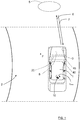
- FIG. 1 schematically shows a top view of an ego vehicle 1 arranged to run at an ego vehicle velocity v on a road 2 in a forward over-ground movement direction F, in the following referred to as ego direction F, where the ego vehicle 1 comprises a vehicle radar system 3.
- the vehicle radar system 3 comprises a radar sensor arrangement 4 that is arranged to distinguish and/or resolve single targets from the surroundings by transmitting signals 6 and receiving reflected signals 7 and using a Doppler effect in a previously well-known manner.
- the vehicle radar system 3 further comprises a main control unit 8 that is connected to the radar sensor arrangement 4 and is arranged to provide radial velocity and azimuth angles of possible target objects 5 by simultaneously sampling and analyzing phase and amplitude of the received signals 7.
- the reflected signals 7 correspond to radar detections, where the main control unit 8 comprises a tracking function that is arranged to group these radar detections as tracked objects, providing a common motion state for an extended detected object.
- the ego vehicle 1 has a center of mass 10 and an angular rotational velocity ⁇ ego • around the center of mass 10, and the radar sensor arrangements 4 has a certain relation to the center of mass 10.
- a yaw sensor device 20 is connected to the main control unit 8.
- the ego vehicle 1 runs in the ego direction F on the road 2, and the vehicle radar system 3 detects an object in the form of an oncoming vehicle 9.
- the ego vehicle's radar system 3 tracks the detected object in the form of the oncoming vehicle 9, here illustrated by means of a plurality of detections 19.
- the vehicles 1, 9 are shown at a plurality of positions as they approach each other.
- a global coordinate system 16 having a global x-axis x glob and a global y-axis y glob is created at the point at which a curve 17 begins. Then, the ego vehicle position and the oncoming vehicle position are both calculated and observed in the global coordinate system 16. Once the ego vehicle 1 is determined to travel straight again, having departed from the curve 17, the global coordinate system 16 is deleted and for a next curve, a new global coordinate-system will be created. This will be described more in detail below.
- the main control unit 8 comprised in the vehicle radar system 3 is arranged to create a global coordinate system 16 at the current position when the ego vehicle 1 is determined to have entered a curve. This is according to some aspects determined in the same way as in the previous examples.
- the main control unit 8 is then arranged to repeatedly perform the following for a plurality of radar cycles:
- the straight line 18 indicating the heading of the tracked object is always calculated based on two positions X track,maxX ,X track,minX . These positions comprise a first position X track,maxX at which the tracked object 9 has the greatest distance to the ego vehicle 1 in the x-direction, and a second position X track,minX at which the tracked object has the smallest distance to the ego vehicle 1 in the x-direction.
- the global oncome angle ⁇ track glob is then determined as the angle of the straight line 18 between the two positions X track,maxX ,X track,minX .
- the oncoming vehicle 9 In order to determine whether the oncoming vehicle 9 should be determined to be crossing or not, it is determined whether the difference angle ⁇ exceeds the threshold angle ⁇ max or not. If the oncoming vehicle 9 is determined to be crossing, suitable safety measure are taken; for example emergency braking, emergency steering and pushing vehicle occupants towards the middle of the ego vehicle 1, suitably by means of one or more airbags.
- the difference angle ⁇ will change while driving on the curve 17; in the beginning of the curve 17 the oncoming vehicle 9 will therefore seem to be a crossing vehicle and only while the two vehicles 1, 9 move along the curve, the difference angle ⁇ will decrease.
- the safety measures are triggered shortly before an impact has been determined to occur. This means that there is enough time to classify the oncoming vehicle 9 as oncoming, and not crossing, when it comes to the final decision, even though at the beginning of the curve it was perhaps misclassified.
- the threshold angle ⁇ max is adaptive, such that in straight driving situations, a first threshold angle ⁇ max1 is used, and in curves a second threshold angle ⁇ max2 is used, where the second threshold angle ⁇ max2 exceeds the first threshold angle ⁇ max1 .
- the first threshold angle ⁇ max1 is about 35°
- the second threshold angle ⁇ max2 is about 45°.
- the main control unit 8 is arranged to determine whether the ego vehicle 1 travels in a curve or not by detecting if the angular rotational velocity ⁇ ego • exceeds a certain threshold ⁇ egomax • , according to some aspects 2 deg/s, as mentioned previously.
- the threshold angle ⁇ max is step-wise reduced to the first threshold angle ⁇ max1 .
- Each subsequent step-wise change is according to some aspects performed for each subsequent radar cycle.
- a radar cycle is one observation phase during which the vehicle radar system 3 is arranged to acquire data, process said data on several signal processing levels and to send out available results.
- This can be a fixed time interval, or it can be a dynamic time interval depending on environment conditions and processing load.
- the main control unit 8 is arranged to perform the above for one or more tracked objects.
- the present disclosure also relates to a method for detecting oncoming vehicles relative an ego vehicle 1.
- the method comprises:
- the method further comprises:
- the method comprises applying one or more safety measures.
- the method comprises:
- the vehicle radar system 3 is comprised in a vehicle environment detection system 40.
- the present disclosure is related to a vehicle environment detection system 40 arranged for any suitable environment detection technology, for example radar as in the examples above, but also Lidar (Light detection and ranging) and/or image detection are conceivable.
- the yaw sensor device 20 is comprised in the vehicle environment detection system 40.
- the vehicle environment detection system 40 generally comprises one or more environment detection sensor arrangements 4.
- the main control unit 8 comprises one or more control unit parts which according to some aspects are combined, adjacent or distributed. One or more of such control unit parts are according to some aspects comprised in the vehicle environment detection system 40.
- the orientation of the coordinates and the coordinate system may have many suitable configurations, generally there is a predetermined axis with reference to which the ego direction 21, the corresponding ego direction angle ⁇ ego , the oncoming direction 18 of the tracked oncoming vehicle 9 and the corresponding oncoming angle ⁇ track, glob are determined.
- the present disclosure relates to a vehicle environment detection system 40 adapted to be mounted in an ego vehicle 1 and comprising at least one vehicle environment sensor arrangement 4 and a main control unit 8, where the vehicle environment detection system 40 is arranged to detect and track at least one oncoming vehicle 9, where the vehicle environment detection system 40 is arranged to determine when the ego vehicle 1 has entered a curve 17.
- the main control unit 8 is arranged to:
- the main control unit 8 is arranged to apply one or more safety measures.
- the vehicle environment detection system 40 comprises a yaw sensor device 20 that is connected to the main control unit 8 and is arranged to enable the main control unit 8 to determine an ego direction F along which the ego vehicle 1 travels and to determine whether the ego vehicle 1 has entered a curve 17.
- the main control unit 8 is arranged to:
- the threshold angle ⁇ max is step-wise reduced to the first threshold angle ⁇ max1 .
- the vehicle environment detection system 40 comprises at least one of a radar system 3, a Lidar (Light detection and ranging) system and/or an image detection system.
- the present disclosure also relates to a method for detecting oncoming vehicles relative an ego vehicle 1, where the method comprises:
- the method further comprises:
- the method comprises applying one or more safety measures.
- the method comprises:
- the method comprises stepwise reducing the threshold angle ⁇ max to the first threshold angle ⁇ max1 .
Landscapes
- Engineering & Computer Science (AREA)
- Radar, Positioning & Navigation (AREA)
- Remote Sensing (AREA)
- Physics & Mathematics (AREA)
- Electromagnetism (AREA)
- Computer Networks & Wireless Communication (AREA)
- General Physics & Mathematics (AREA)
- Radar Systems Or Details Thereof (AREA)
- Traffic Control Systems (AREA)
Abstract
- Determine an ego direction (21) along which the ego vehicle (1) travels with a corresponding ego direction angle (γego) with respect to a predetermined axis (xglob).
- Determine a measured oncoming direction (18) of said tracked oncoming vehicle (9) with a corresponding oncoming angle (θtrack, glob) with respect to the predetermined axis (xglob) during a plurality of radar cycles.
- Determine a difference angle (δ) between said measured oncoming direction (18) and the ego direction (21).
- Compare the difference angle (δ) with a threshold angle (θmax), and to determine that the oncoming vehicle (9) is crossing if the difference angle (δ) exceeds the threshold angle (θmax).
Description
- The present disclosure relates to a vehicle environment detection system adapted to be mounted in an ego vehicle and comprising at least one vehicle environment sensor arrangement and a main control unit. The vehicle environment detection system is arranged to detect and track at least one oncoming vehicle.
- Today, vehicle environment detection systems, such as for example camera systems, Doppler radar systems and Lidar (Light detection and ranging) systems, can be mounted on a vehicle in order to detect objects in order to implement automated vehicle systems such as speed control and collision prevention.
- Radar systems are arranged to produce output comprising a series of reflection points as measured by radar sensors. These reflection points can be treated as separate detections or grouped as tracked objects, providing a common motion state for an extended object.
- There are previously known vehicle occupant safety systems which detect side-impacts before the actual crash. In the case that it has been determined that a crash is imminent, vehicle occupants can for example be pushed towards the middle of the car.
- To avoid false positives, a sensor used for this purpose has to robustly classify tracks as oncoming or crossing traffic, especially in curves.
-
US 8,847,792 discloses estimating the risk of an impact of an oncoming vehicle based on the movement amount of a radar reflection point on the oncoming vehicle when the reflection point varies in a vehicle width direction from the left front end toward the right front end of an oncoming vehicle. The acquired data is used for determination of the possibility of collision with an oncoming vehicle, on a curved road or the like. - It is, however, desired to provide a vehicle radar system that is adapted to classify tracks as oncoming or crossing traffic, especially in curves in an accurate, efficient and reliable manner, which also is an object of the present disclosure. In the case of oncoming traffic, it is determined whether an oncoming vehicle will collide with an ego vehicle.
- Said object is achieved by means of a vehicle environment detection system adapted to be mounted in an ego vehicle and comprising at least one vehicle environment sensor arrangement and a main control unit. The vehicle environment detection system is arranged to detect and track at least one oncoming vehicle, and to determine whether the ego vehicle has entered a curve. When the vehicle environment detection system has determined that the ego vehicle has entered a curve, for each tracked oncoming vehicle, the main control unit is arranged to:
- Determine an ego direction along which the ego vehicle travels with a corresponding ego direction angle with respect to a predetermined axis.
- Determine a measured oncoming direction of said tracked oncoming vehicle with a corresponding oncoming angle with respect to the predetermined axis during a plurality of radar cycles.
- Determine a difference angle between said measured oncoming direction and the ego direction.
- Compare the difference angle with a threshold angle.
- Determine that the oncoming vehicle is crossing if the difference angle has been determined to exceed the threshold angle.
- Said object is also achieved by means of a method for detecting oncoming vehicles relative an ego vehicle. The method comprises: Detecting and tracking at least one oncoming vehicle and determining whether the ego vehicle has entered a curve.
- When it has been determined that the ego vehicle has entered a curve, for each tracked oncoming vehicle, the method further comprises determining an ego direction along which the ego vehicle travels with a corresponding ego direction angle with respect to a predetermined axis and determining a measured oncoming direction of said tracked oncoming vehicle with a corresponding oncoming angle with respect to the predetermined axis during a plurality of radar cycles.
- The method then comprises determining a difference angle between said measured oncoming direction and the ego direction, comparing the difference angle with a threshold angle, and determining that the oncoming vehicle is crossing if the difference angle has been determined to exceed the threshold angle.
- A number of advantages are obtained by means of the present disclosure. Mainly, a vehicle radar system is provided that determines whether an oncoming vehicle will collide with an ego vehicle in a more accurate, efficient and reliable manner, than previously described.
- According to some aspects, for each tracked oncoming vehicle that has been determined to be crossing, one or more safety measures is/are applied.
- According to some aspects, for each radar cycle, the main control unit is arranged to determine the measured oncoming direction as a straight line based on two positions, which positions comprise a first position at which the oncoming vehicle has a greatest distance to the ego vehicle along the predetermined axis, and a second position at which the oncoming vehicle has a smallest distance to the ego vehicle along the predetermined axis. The main control unit is then arranged to determine the oncome angle as an angle of the straight line between the two positions.
- According to some aspects, when the vehicle environment detection system has determined that the ego vehicle has entered a curve, the main control unit is arranged to increase the threshold angle stepwise from a first threshold angle to a second threshold angle. This is performed in a in a step-wise manner according to:


- In this manner, the reliability of the vehicle environment detection system is increased.
- According to some aspects, when the vehicle environment detection system has determined that the ego vehicle has left said curve, the threshold angle is step-wise reduced to the first threshold angle.
- Other aspects of the present disclosure are disclosed in the dependent claims.
- The present disclosure will now be described more in detail with reference to the appended drawings, where:
- Figure 1
- shows a schematic top view of an ego vehicle;
- Figure 2
- shows a schematic top view of an ego vehicle and an oncoming vehicle;
- Figure 3
- shows a flowchart for a procedure according to the present disclosure;
- Figure 4
- shows a flowchart for a method according to the present disclosure; and
- Figure 5
- shows a flowchart for a further method according to the present disclosure.
-
Figure 1 schematically shows a top view of anego vehicle 1 arranged to run at an ego vehicle velocity v on aroad 2 in a forward over-ground movement direction F, in the following referred to as ego direction F, where theego vehicle 1 comprises avehicle radar system 3. Thevehicle radar system 3 comprises a radar sensor arrangement 4 that is arranged to distinguish and/or resolve single targets from the surroundings by transmittingsignals 6 and receivingreflected signals 7 and using a Doppler effect in a previously well-known manner. Thevehicle radar system 3 further comprises amain control unit 8 that is connected to the radar sensor arrangement 4 and is arranged to provide radial velocity and azimuth angles ofpossible target objects 5 by simultaneously sampling and analyzing phase and amplitude of the receivedsignals 7. - The
reflected signals 7 correspond to radar detections, where themain control unit 8 comprises a tracking function that is arranged to group these radar detections as tracked objects, providing a common motion state for an extended detected object. - The
ego vehicle 1 has a center ofmass 10 and an angular rotational velocity
mass 10, and the radar sensor arrangements 4 has a certain relation to the center ofmass 10. In order to detect an ego direction angle γego, that corresponds to the ego direction F, and the corresponding rotational velocity
yaw sensor device 20 is connected to themain control unit 8. - With reference also to
Figure 2 , theego vehicle 1 runs in the ego direction F on theroad 2, and thevehicle radar system 3 detects an object in the form of anoncoming vehicle 9. The ego vehicle'sradar system 3 tracks the detected object in the form of theoncoming vehicle 9, here illustrated by means of a plurality ofdetections 19. Thevehicles - A
global coordinate system 16 having a global x-axis xglob and a global y-axis yglob is created at the point at which acurve 17 begins. Then, the ego vehicle position and the oncoming vehicle position are both calculated and observed in theglobal coordinate system 16. Once theego vehicle 1 is determined to travel straight again, having departed from thecurve 17, theglobal coordinate system 16 is deleted and for a next curve, a new global coordinate-system will be created. This will be described more in detail below. - For the tracked oncoming
vehicle 9, themain control unit 8 comprised in thevehicle radar system 3 is arranged to create a global coordinatesystem 16 at the current position when theego vehicle 1 is determined to have entered a curve. This is according to some aspects determined in the same way as in the previous examples. - With reference also to
Figure 3 , showing a flowchart of the procedure described below, themain control unit 8 is then arranged to repeatedly perform the following for a plurality of radar cycles: - 22) Update vehicle and sensor position according to:

x is a state-vector consisting of x-position and y-position, and i is an increasing step index indicating that the current value always is calculated based on the value of the last cycle. - 23) Shift track position and track velocity to the global coordinate
system 16 according to:
- 24) Find maximum and minimum positions Xtrack,maxX ,Xtrack,minX of tracked detections in the global x-direction.
- 25) Determine whether new valid positions Xtrack,maxX,Xtrack,minX have been found. This is needed since there is a minimum distance between the positions Xtrack,maxX,Xtrack,minX . If there are no valid positions, the procedure is repeated from step 1). When valid positions Xtrack,maxX,Xtrack,minX have been found once, the procedure always continues to the following step 5) for every following radar cycle.
- 26) When new valid positions Xtrack,maxX,Xtrack,minX have been found, determine a
straight line 18 that fits between the positions Xtrack,maxX,Xtrack,minX , and determine a global oncome angle θtrack, glob of the trackedobject 9 between thestraight line 18 and the global x-axis xglob. - 27) Calculate a global oncome difference angle δ as a difference between the global oncome angle θtrack, glob and the ego direction angle γego between a
determined ego direction 21 and the global x-axis xglob. - 28) Compare the global oncome difference angle δ with a threshold angle θmax.
- For each radar cycle, the
straight line 18 indicating the heading of the tracked object is always calculated based on two positions Xtrack,maxX,Xtrack,minX . These positions comprise a first position Xtrack,maxX at which the trackedobject 9 has the greatest distance to theego vehicle 1 in the x-direction, and a second position Xtrack,minX at which the tracked object has the smallest distance to theego vehicle 1 in the x-direction. - For each radar cycle, the global oncome angle θtrack, glob is then determined as the angle of the
straight line 18 between the two positions Xtrack,maxX,Xtrack,minX. - In order to determine whether the oncoming
vehicle 9 should be determined to be crossing or not, it is determined whether the difference angle δ exceeds the threshold angle θmax or not. If theoncoming vehicle 9 is determined to be crossing, suitable safety measure are taken; for example emergency braking, emergency steering and pushing vehicle occupants towards the middle of theego vehicle 1, suitably by means of one or more airbags. - The difference angle δ will change while driving on the
curve 17; in the beginning of thecurve 17 the oncomingvehicle 9 will therefore seem to be a crossing vehicle and only while the twovehicles - The safety measures are triggered shortly before an impact has been determined to occur. This means that there is enough time to classify the
oncoming vehicle 9 as oncoming, and not crossing, when it comes to the final decision, even though at the beginning of the curve it was perhaps misclassified. - According to some aspects, the threshold angle θmax is adaptive, such that in straight driving situations, a first threshold angle θmax1 is used, and in curves a second threshold angle θmax2 is used, where the second threshold angle θmax2 exceeds the first threshold angle θmax1. According to some aspects, the first threshold angle θmax1 is about 35°, and the second threshold angle θmax2 is about 45°.
- For this purpose the
main control unit 8 is arranged to determine whether theego vehicle 1 travels in a curve or not by detecting if the angular rotational velocity

aspects 2 deg/s, as mentioned previously. According to some aspects, If
main control unit 8 is arranged to increase the threshold angle θmax stepwise from the first threshold angle θmax1 to the second threshold angle θmax2 in a step-wise manner according to:
- When the
main control unit 8 determines that
- Each subsequent step-wise change is according to some aspects performed for each subsequent radar cycle.
- In this context, a radar cycle is one observation phase during which the
vehicle radar system 3 is arranged to acquire data, process said data on several signal processing levels and to send out available results. This can be a fixed time interval, or it can be a dynamic time interval depending on environment conditions and processing load. - The
main control unit 8 is arranged to perform the above for one or more tracked objects. - With reference to
Figure 4 , the present disclosure also relates to a method for detecting oncoming vehicles relative anego vehicle 1. The method comprises: - 41: Detecting and tracking at least one
oncoming vehicle 9; and - 42: determining whether the ego vehicle (1) has entered a
curve 17. - When it has been determined that the
ego vehicle 1 has entered acurve 17, for each tracked oncomingvehicle 9, the method further comprises: - 43: Determining an
ego direction 21 along which theego vehicle 1 travels with a corresponding ego direction angle γego with respect to a predetermined axis xglob. - 44: Determining a measured oncoming
direction 18 of said trackedoncoming vehicle 9 with a corresponding oncoming angle θtrack, glob with respect to the predetermined axis xglob during a plurality of radar cycles. - 45: Determining a difference angle δ between said measured oncoming
direction 18 and theego direction 21. - 46: Comparing the difference angle δ with a threshold angle θmax.
- 47: Determining that the
oncoming vehicle 9 is crossing if the difference angle δ has been determined to exceed the threshold angle θmax. - According to some aspects, for each tracked oncoming
vehicle 9 that has been determined to be crossing, the method comprises applying one or more safety measures. - With reference to
Figure 5 , regarding determining the measured oncomingdirection 18, for each radar cycle, the method comprises: - 48: Determining the measured oncoming
direction 18 as astraight line 18 based on two positions Xtrack,maxX,Xtrack,minX , which positions Xtrack,maxX,Xtrack,minX comprise a first position Xtrack,maxX at which theoncoming vehicle 9 has a greatest distance to theego vehicle 1 along the predetermined axis xglob, and a second position Xtrack,minX at which theoncoming vehicle 9 has a smallest distance to theego vehicle 1 along the predetermined axis xglob. - 49: Determining the oncome angle θtrack, glob as an angle of the
straight line 18 between the two positions Xtrack,maxX ,Xtrack,minX . - The present disclosure is not limited to the examples above, but may vary freely within the scope of the appended claims. For example, the
vehicle radar system 3 is comprised in a vehicleenvironment detection system 40. Generally, the present disclosure is related to a vehicleenvironment detection system 40 arranged for any suitable environment detection technology, for example radar as in the examples above, but also Lidar (Light detection and ranging) and/or image detection are conceivable. According to some aspects, when a yaw sensor device is present, theyaw sensor device 20 is comprised in the vehicleenvironment detection system 40. - The vehicle
environment detection system 40 generally comprises one or more environment detection sensor arrangements 4. - The
main control unit 8 comprises one or more control unit parts which according to some aspects are combined, adjacent or distributed. One or more of such control unit parts are according to some aspects comprised in the vehicleenvironment detection system 40. - The orientation of the coordinates and the coordinate system may have many suitable configurations, generally there is a predetermined axis with reference to which the
ego direction 21, the corresponding ego direction angle γego, the oncomingdirection 18 of the tracked oncomingvehicle 9 and the corresponding oncoming angle θtrack, glob are determined. - Generally, the present disclosure relates to a vehicle
environment detection system 40 adapted to be mounted in anego vehicle 1 and comprising at least one vehicle environment sensor arrangement 4 and amain control unit 8, where the vehicleenvironment detection system 40 is arranged to detect and track at least oneoncoming vehicle 9, where the vehicleenvironment detection system 40 is arranged to determine when theego vehicle 1 has entered acurve 17. When the vehicleenvironment detection system 40 has determined that theego vehicle 1 has entered acurve 17, for each tracked oncomingvehicle 9 themain control unit 8 is arranged to: - determine an
ego direction 21 along which theego vehicle 1 travels with a corresponding ego direction angle γego with respect to a predetermined axis xglob; - determine a measured oncoming
direction 18 of said trackedoncoming vehicle 9 with a corresponding oncoming angle θtrack, glob with respect to the predetermined axis xglob during a plurality of radar cycles; - determine a difference angle δ between said measured oncoming
direction 18 and theego direction 21; - compare the difference angle δ with a threshold angle θmax; and
- determine that the
oncoming vehicle 9 is crossing if the difference angle δ has been determined to exceed the threshold angle θmax. - According to some aspects, for each tracked oncoming
vehicle 9 that has been determined to be crossing, themain control unit 8 is arranged to apply one or more safety measures. - According to some aspects, the vehicle
environment detection system 40 comprises ayaw sensor device 20 that is connected to themain control unit 8 and is arranged to enable themain control unit 8 to determine an ego direction F along which theego vehicle 1 travels and to determine whether theego vehicle 1 has entered acurve 17. - According to some aspects, for each radar cycle, the
main control unit 8 is arranged to: - determine the measured oncoming
direction 18 as astraight line 18 based on two positions Xtrack,maxX,Xtrack,minX, which positions Xtrack,maxX,Xtrack,minX comprise a first position Xtrack,maxX at which theoncoming vehicle 9 has a greatest distance to theego vehicle 1 along the predetermined axis xglob, and a second position Xtrack,minX at which theoncoming vehicle 9 has a smallest distance to theego vehicle 1 along the predetermined axis xglob; and - determine the oncome angle θtrack, glob as an angle of the
straight line 18 between the two positions Xtrack,maxX,Xtrack,minX . - According to some aspects, when the vehicle
environment detection system 40 has determined that theego vehicle 1 has entered acurve 17, themain control unit 8 is arranged to increase the threshold angle θmax stepwise from a first threshold angle θmax1 to a second threshold angle θmax2 in a step-wise manner according to:

ego vehicle 1, and where the second threshold angle θmax2 exceeds the first threshold angle θmax1. - According to some aspects, when the vehicle
environment detection system 40 has determined that theego vehicle 1 has left saidcurve 17, the threshold angle θmax is step-wise reduced to the first threshold angle θmax1. - According to some aspects, the vehicle
environment detection system 40 comprises at least one of aradar system 3, a Lidar (Light detection and ranging) system and/or an image detection system. - Generally, the present disclosure also relates to a method for detecting oncoming vehicles relative an
ego vehicle 1, where the method comprises: - 41: detecting and tracking at least one
oncoming vehicle 9; and - 42: determining whether the
ego vehicle 1 has entered acurve 17. - When it has been determined that the
ego vehicle 1 has entered acurve 17, for each tracked oncomingvehicle 9, the method further comprises: - 43: determining an
ego direction 21 along which theego vehicle 1 travels with a corresponding ego direction angle γego with respect to a predetermined axis xglob; - 44: determining a measured oncoming
direction 18 of said trackedoncoming vehicle 9 with a corresponding oncoming angle θtrack, glob with respect to the predetermined axis xglob during a plurality of radar cycles; - 45: determining a difference angle δ between said measured oncoming
direction 18 and theego direction 21; - 46: comparing the difference angle δ with a threshold angle θmax; and
- 47: determining that the
oncoming vehicle 9 is crossing if the difference angle δ has been determined to exceed the threshold angle θmax. - According to some aspects, for each tracked oncoming
vehicle 9 that has been determined to be crossing, the method comprises applying one or more safety measures. - According to some aspects, for each radar cycle, the method comprises:
- 48: determining the measured oncoming
direction 18 as astraight line 18 based on two positions Xtrack,maxX,Xtrack,minX , which positions Xtrack,maxX ,Xtrack,minX comprise a first position Xtrack,maxX at which theoncoming vehicle 9 has a greatest distance to theego vehicle 1 along the predetermined axis xglob, and a second position Xtrack,minX at which theoncoming vehicle 9 has a smallest distance to theego vehicle 1 along the predetermined axis xglob: and - 49: determining the oncome angle θtrack, glob as an angle of the
straight line 18 between the two positions Xtrack,maxX,Xtrack,minX . - According to some aspects, when it has been determined that the
ego vehicle 1 has entered acurve 17, the method comprises increasing the threshold angle θmax stepwise from a first threshold angle θmax1 to a second threshold angle θmax2 in a stepwise manner according to:

ego vehicle 1, and where the second threshold angle θmax2 exceeds the first threshold angle θmax1. - According to some aspects, when it has been determined that the
ego vehicle 1 has left saidcurve 17, the method comprises stepwise reducing the threshold angle θmax to the first threshold angle θmax1.
Claims (12)
- A vehicle environment detection system (40) adapted to be mounted in an ego vehicle (1) and comprising at least one vehicle environment sensor arrangement (4) and a main control unit (8), where the vehicle environment detection system (40) is arranged to detect and track at least one oncoming vehicle (9), where the vehicle environment detection system (40) is arranged to determine when the ego vehicle (1) has entered a curve (17), characterized in that when the vehicle environment detection system (40) has determined that the ego vehicle (1) has entered a curve (17), for each tracked oncoming vehicle (9) the main control unit (8) is arranged to:- determine an ego direction (21) along which the ego vehicle (1) travels with a corresponding ego direction angle (γego) with respect to a predetermined axis (xglob) ;- determine a measured oncoming direction (18) of said tracked oncoming vehicle (9) with a corresponding oncoming angle (θtrack, glob) with respect to the predetermined axis (xglob) during a plurality of radar cycles;- determine a difference angle (δ) between said measured oncoming direction (18) and the ego direction (21);- compare the difference angle (δ) with a threshold angle (δmax); and- determine that the oncoming vehicle (9) is crossing if the difference angle (δ) has been determined to exceed the threshold angle (δmax).
- The vehicle environment detection system (40) according to claim 1, characterized in that for each tracked oncoming vehicle (9) that has been determined to be crossing, the main control unit (8) is arranged to apply one or more safety measures.
- The vehicle environment detection system (40) according to any one of the claims 1 or 2, characterized in that the vehicle environment detection system (40) comprises a yaw sensor device (20) that is connected to the main control unit (8) and is arranged to enable the main control unit (8) to determine an ego direction (F) along which the ego vehicle (1) travels and to determine whether the ego vehicle (1) has entered a curve (17).
- The vehicle environment detection system (2) according to any one of the previous claims, characterized in that for each radar cycle, the main control unit (8) is arranged to:- determine the measured oncoming direction (18) as a straight line (18) based on two positions (Xtrack,maxX,Xtrack,minX ), which positions (Xtrack,maxX,Xtrack,minX ) comprise a first position (Xtrack,maxX ) at which the oncoming vehicle (9) has a greatest distance to the ego vehicle 1 along the predetermined axis (xglob), and a second position (Xtrack,minX ) at which the oncoming vehicle (9) has a smallest distance to the ego vehicle 1 along the predetermined axis (xglob) ; and- determine the oncome angle (θtrack, glob) as an angle of the straight line (18) between the two positions (Xtrack,maxX,Xtrack,minX ).
- The vehicle environment detection system (40) according to any one of the previous claims, characterized in that when the vehicle environment detection system (40) has determined that the ego vehicle (1) has entered a curve (17), the main control unit (8) is arranged to increase the threshold angle (θmax) stepwise from a first threshold angle (θmax1) to a second threshold angle (θmax2) in a step-wise manner according to:


- The vehicle environment detection system (40) according to claim 5, characterized in that when the vehicle environment detection system (40) has determined that the ego vehicle (1) has left said curve (17), the threshold angle (θmax) is step-wise reduced to the first threshold angle (θmax1)
- The vehicle environment detection system (40) according to any one of the previous claims, characterized in that the vehicle environment detection system (40) comprises at least one of a radar system (3), a Lidar, Light detection and ranging, system and/or an image detection system.
- A method for detecting oncoming vehicles relative an ego vehicle (1), where the method comprises:(41) detecting and tracking at least one oncoming vehicle (9); and(42) determining whether the ego vehicle (1) has entered a curve (17),characterized in that when it has been determined that the ego vehicle (1) has entered a curve (17), for each tracked oncoming vehicle (9), the method further comprises:(43) determining an ego direction (21) along which the ego vehicle (1) travels with a corresponding ego direction angle (γego) with respect to a predetermined axis (xglob) ;(44) determining a measured oncoming direction (18) of said tracked oncoming vehicle (9) with a corresponding oncoming angle (θtrack, glob) with respect to the predetermined axis (xglob) during a plurality of radar cycles;(45) determining a difference angle (δ) between said measured oncoming direction (18) and the ego direction (21);(46) comparing the difference angle (δ) with a threshold angle (θmax) ; and(47) determining that the oncoming vehicle (9) is crossing if the difference angle (δ) has been determined to exceed the threshold angle (θmax).
- The method according to claim 8, characterized in that for each tracked oncoming vehicle (9) that has been determined to be crossing, the method comprises applying one or more safety measures.
- The method according to any one of the claims 8 or 9, characterized in that for each radar cycle, the method comprises:(48) determining the measured oncoming direction (18) as a straight line (18) based on two positions (Xtrack,maxX,Xtrack,minX ), which positions (Xtrack,maxX ,Xtrack,minX ) comprise a first position (Xtrack,maxX ) at which the oncoming vehicle (9) has a greatest distance to the ego vehicle 1 along the predetermined axis (xglob), and a second position (Xtrack,minX ) at which the oncoming vehicle (9) has a smallest distance to the ego vehicle 1 along the predetermined axis (xglob) ; and(49) determining the oncome angle (θtrack, glob) as an angle of the straight line (18) between the two positions (Xtrack,maxX,Xtrack,minX ).
- The method according to any one of the claims 8-10, characterized in that when it has been determined that the ego vehicle (1) has entered a curve (17), the method comprises increasing the threshold angle (θmax) stepwise from a first threshold angle (θmax1) to a second threshold angle (θmax2) in a step-wise manner according to:


- The method according to claim 11, characterized in that when it has been determined that the ego vehicle (1) has left said curve (17), the method comprises step-wise reducing the threshold angle (θmax) to the first threshold angle (θmax1)
Priority Applications (5)
| Application Number | Priority Date | Filing Date | Title |
|---|---|---|---|
| EP17175129.0A EP3413083B1 (en) | 2017-06-09 | 2017-06-09 | A vehicle system for detection of oncoming vehicles |
| PCT/EP2018/064771 WO2018224500A1 (en) | 2017-06-09 | 2018-06-05 | A vehicle system for detection of oncoming vehicles |
| JP2019563885A JP6906638B2 (en) | 2017-06-09 | 2018-06-05 | Vehicle system for detecting oncoming vehicles |
| CN201880037107.XA CN110709727B (en) | 2017-06-09 | 2018-06-05 | Vehicle system for detecting oncoming vehicles |
| US16/619,785 US11435474B2 (en) | 2017-06-09 | 2018-06-05 | Vehicle system for detection of oncoming vehicles |
Applications Claiming Priority (1)
| Application Number | Priority Date | Filing Date | Title |
|---|---|---|---|
| EP17175129.0A EP3413083B1 (en) | 2017-06-09 | 2017-06-09 | A vehicle system for detection of oncoming vehicles |
Publications (2)
| Publication Number | Publication Date |
|---|---|
| EP3413083A1 true EP3413083A1 (en) | 2018-12-12 |
| EP3413083B1 EP3413083B1 (en) | 2020-03-11 |
Family
ID=59034555
Family Applications (1)
| Application Number | Title | Priority Date | Filing Date |
|---|---|---|---|
| EP17175129.0A Active EP3413083B1 (en) | 2017-06-09 | 2017-06-09 | A vehicle system for detection of oncoming vehicles |
Country Status (5)
| Country | Link |
|---|---|
| US (1) | US11435474B2 (en) |
| EP (1) | EP3413083B1 (en) |
| JP (1) | JP6906638B2 (en) |
| CN (1) | CN110709727B (en) |
| WO (1) | WO2018224500A1 (en) |
Families Citing this family (2)
| Publication number | Priority date | Publication date | Assignee | Title |
|---|---|---|---|---|
| EP3413082B1 (en) * | 2017-06-09 | 2020-01-01 | Veoneer Sweden AB | A vehicle system for detection of oncoming vehicles |
| JP7347275B2 (en) * | 2020-03-11 | 2023-09-20 | 株式会社デンソー | Axis misalignment detection device and axis misalignment detection program |
Citations (4)
| Publication number | Priority date | Publication date | Assignee | Title |
|---|---|---|---|---|
| US7885766B2 (en) * | 2004-11-22 | 2011-02-08 | Honda Motor Co., Ltd. | Subject and oncoming vehicle departure determination and collision avoidance apparatus |
| US20110175767A1 (en) * | 2008-12-22 | 2011-07-21 | Toyota Jidosha Kabushiki Kaisha | Radar apparatus, and measurement method used in the radar apparatus |
| US8847792B2 (en) | 2010-09-24 | 2014-09-30 | Toyota Jidosha Kabushiki Kaisha | Object detection apparatus and object detection program |
| US20160207534A1 (en) * | 2015-01-20 | 2016-07-21 | Toyota Jidosha Kabushiki Kaisha | Collision avoidance control system and control method |
Family Cites Families (19)
| Publication number | Priority date | Publication date | Assignee | Title |
|---|---|---|---|---|
| JP3031119B2 (en) * | 1993-06-22 | 2000-04-10 | トヨタ自動車株式会社 | Vehicle collision prevention device |
| US5854987A (en) * | 1995-02-22 | 1998-12-29 | Honda Giken Kogyo Kabushiki Kaisha | Vehicle steering control system using navigation system |
| JP2000131436A (en) * | 1998-10-29 | 2000-05-12 | Aisin Seiki Co Ltd | Curve estimation method and vehicle speed control device using the same |
| JP3658519B2 (en) * | 1999-06-28 | 2005-06-08 | 株式会社日立製作所 | Vehicle control system and vehicle control device |
| JP3800007B2 (en) * | 2001-01-09 | 2006-07-19 | 日産自動車株式会社 | Braking control device |
| JP4647201B2 (en) * | 2003-12-05 | 2011-03-09 | 富士重工業株式会社 | Vehicle travel control device |
| DE102004059002A1 (en) * | 2004-12-08 | 2006-06-14 | Daimlerchrysler Ag | Method for adapting intervention parameters of an assistance system of a vehicle |
| JP4906398B2 (en) * | 2006-05-15 | 2012-03-28 | アルパイン株式会社 | In-vehicle road shape identification device, in-vehicle system, road shape identification method and periphery monitoring method |
| JP4879082B2 (en) * | 2007-05-01 | 2012-02-15 | アルパイン株式会社 | Warning guidance device and warning guidance method |
| JP5038986B2 (en) * | 2008-07-04 | 2012-10-03 | トヨタ自動車株式会社 | Collision prediction device |
| JP2011086139A (en) * | 2009-10-16 | 2011-04-28 | Honda Motor Co Ltd | Device for avoiding collision of vehicle |
| US9196163B2 (en) * | 2011-08-26 | 2015-11-24 | Toyota Jidosha Kabushiki Kaisha | Driving support apparatus and driving support method |
| JP5846109B2 (en) * | 2012-11-20 | 2016-01-20 | 株式会社デンソー | Collision determination device and collision avoidance system |
| JP2015230566A (en) * | 2014-06-04 | 2015-12-21 | トヨタ自動車株式会社 | Driving support device |
| JP6409680B2 (en) * | 2015-05-29 | 2018-10-24 | 株式会社デンソー | Driving support device and driving support method |
| JP6819281B2 (en) * | 2016-12-27 | 2021-01-27 | 株式会社デンソー | Collision detection device and collision detection system |
| JP6961995B2 (en) * | 2017-05-12 | 2021-11-05 | トヨタ自動車株式会社 | Driving support device |
| EP3413082B1 (en) * | 2017-06-09 | 2020-01-01 | Veoneer Sweden AB | A vehicle system for detection of oncoming vehicles |
| DE102017210377A1 (en) * | 2017-06-21 | 2018-12-27 | Honda Motor Co., Ltd. | Vehicle travel support device |
-
2017
- 2017-06-09 EP EP17175129.0A patent/EP3413083B1/en active Active
-
2018
- 2018-06-05 WO PCT/EP2018/064771 patent/WO2018224500A1/en not_active Ceased
- 2018-06-05 US US16/619,785 patent/US11435474B2/en active Active
- 2018-06-05 CN CN201880037107.XA patent/CN110709727B/en active Active
- 2018-06-05 JP JP2019563885A patent/JP6906638B2/en not_active Expired - Fee Related
Patent Citations (4)
| Publication number | Priority date | Publication date | Assignee | Title |
|---|---|---|---|---|
| US7885766B2 (en) * | 2004-11-22 | 2011-02-08 | Honda Motor Co., Ltd. | Subject and oncoming vehicle departure determination and collision avoidance apparatus |
| US20110175767A1 (en) * | 2008-12-22 | 2011-07-21 | Toyota Jidosha Kabushiki Kaisha | Radar apparatus, and measurement method used in the radar apparatus |
| US8847792B2 (en) | 2010-09-24 | 2014-09-30 | Toyota Jidosha Kabushiki Kaisha | Object detection apparatus and object detection program |
| US20160207534A1 (en) * | 2015-01-20 | 2016-07-21 | Toyota Jidosha Kabushiki Kaisha | Collision avoidance control system and control method |
Also Published As
| Publication number | Publication date |
|---|---|
| JP6906638B2 (en) | 2021-07-21 |
| EP3413083B1 (en) | 2020-03-11 |
| CN110709727B (en) | 2023-04-07 |
| US11435474B2 (en) | 2022-09-06 |
| WO2018224500A1 (en) | 2018-12-13 |
| JP2020521237A (en) | 2020-07-16 |
| US20200132833A1 (en) | 2020-04-30 |
| CN110709727A (en) | 2020-01-17 |
Similar Documents
| Publication | Publication Date | Title |
|---|---|---|
| US10559205B2 (en) | Object existence determination method and apparatus | |
| EP1065520B1 (en) | Vehicle control method and vehicle warning method | |
| US8112223B2 (en) | Method for measuring lateral movements in a driver assistance system | |
| US9886858B2 (en) | Lane change detection | |
| EP2056123B1 (en) | Collision avoidance and warning system and method | |
| US20150239472A1 (en) | Vehicle-installed obstacle detection apparatus having function for judging motion condition of detected object | |
| EP3176603B1 (en) | A vehicle radar system | |
| KR102054926B1 (en) | System and method for detecting close cut-in vehicle based on free space signal | |
| CN104077926A (en) | Vehicle-installation intersection judgment apparatus and program | |
| JP2007317018A (en) | Collision determination device | |
| EP2100164B1 (en) | Surroundings monitoring apparatus for a motor vehicle | |
| KR20200108464A (en) | Method and apparatus for detecting critical transverse movement | |
| US12024175B2 (en) | Vehicle system for detection of oncoming vehicles | |
| JP2002175599A (en) | Lane position estimation device for preceding vehicle or target | |
| US11435474B2 (en) | Vehicle system for detection of oncoming vehicles | |
| US20050004719A1 (en) | Device and method for determining the position of objects in the surroundings of a motor vehicle | |
| US12164036B2 (en) | Object recognition via indirect signal reflection | |
| EP4170384B1 (en) | Target detection system and method for vehicle | |
| JPH11167699A (en) | Vehicle object recognition device | |
| EP3422045A1 (en) | A system for enhanced object tracking | |
| JP2008082871A (en) | Vehicle obstacle detection device | |
| JP2011240790A (en) | Preceding vehicle detection device | |
| CN114402224A (en) | Method for object tracking |
Legal Events
| Date | Code | Title | Description |
|---|---|---|---|
| PUAI | Public reference made under article 153(3) epc to a published international application that has entered the european phase |
Free format text: ORIGINAL CODE: 0009012 |
|
| STAA | Information on the status of an ep patent application or granted ep patent |
Free format text: STATUS: THE APPLICATION HAS BEEN PUBLISHED |
|
| AK | Designated contracting states |
Kind code of ref document: A1 Designated state(s): AL AT BE BG CH CY CZ DE DK EE ES FI FR GB GR HR HU IE IS IT LI LT LU LV MC MK MT NL NO PL PT RO RS SE SI SK SM TR |
|
| AX | Request for extension of the european patent |
Extension state: BA ME |
|
| STAA | Information on the status of an ep patent application or granted ep patent |
Free format text: STATUS: REQUEST FOR EXAMINATION WAS MADE |
|
| 17P | Request for examination filed |
Effective date: 20190611 |
|
| RBV | Designated contracting states (corrected) |
Designated state(s): AL AT BE BG CH CY CZ DE DK EE ES FI FR GB GR HR HU IE IS IT LI LT LU LV MC MK MT NL NO PL PT RO RS SE SI SK SM TR |
|
| GRAP | Despatch of communication of intention to grant a patent |
Free format text: ORIGINAL CODE: EPIDOSNIGR1 |
|
| STAA | Information on the status of an ep patent application or granted ep patent |
Free format text: STATUS: GRANT OF PATENT IS INTENDED |
|
| RIC1 | Information provided on ipc code assigned before grant |
Ipc: G01S 13/93 20060101AFI20190701BHEP Ipc: G01S 17/93 20060101ALN20190701BHEP |
|
| INTG | Intention to grant announced |
Effective date: 20190729 |
|
| GRAS | Grant fee paid |
Free format text: ORIGINAL CODE: EPIDOSNIGR3 |
|
| GRAJ | Information related to disapproval of communication of intention to grant by the applicant or resumption of examination proceedings by the epo deleted |
Free format text: ORIGINAL CODE: EPIDOSDIGR1 |
|
| GRAL | Information related to payment of fee for publishing/printing deleted |
Free format text: ORIGINAL CODE: EPIDOSDIGR3 |
|
| STAA | Information on the status of an ep patent application or granted ep patent |
Free format text: STATUS: REQUEST FOR EXAMINATION WAS MADE |
|
| GRAP | Despatch of communication of intention to grant a patent |
Free format text: ORIGINAL CODE: EPIDOSNIGR1 |
|
| STAA | Information on the status of an ep patent application or granted ep patent |
Free format text: STATUS: GRANT OF PATENT IS INTENDED |
|
| INTC | Intention to grant announced (deleted) | ||
| RIC1 | Information provided on ipc code assigned before grant |
Ipc: G01S 13/93 20060101AFI20191212BHEP Ipc: G01S 17/93 20060101ALN20191212BHEP |
|
| INTG | Intention to grant announced |
Effective date: 20200103 |
|
| GRAA | (expected) grant |
Free format text: ORIGINAL CODE: 0009210 |
|
| STAA | Information on the status of an ep patent application or granted ep patent |
Free format text: STATUS: THE PATENT HAS BEEN GRANTED |
|
| AK | Designated contracting states |
Kind code of ref document: B1 Designated state(s): AL AT BE BG CH CY CZ DE DK EE ES FI FR GB GR HR HU IE IS IT LI LT LU LV MC MK MT NL NO PL PT RO RS SE SI SK SM TR |
|
| REG | Reference to a national code |
Ref country code: GB Ref legal event code: FG4D |
|
| REG | Reference to a national code |
Ref country code: CH Ref legal event code: EP |
|
| REG | Reference to a national code |
Ref country code: AT Ref legal event code: REF Ref document number: 1243845 Country of ref document: AT Kind code of ref document: T Effective date: 20200315 |
|
| REG | Reference to a national code |
Ref country code: IE Ref legal event code: FG4D |
|
| REG | Reference to a national code |
Ref country code: DE Ref legal event code: R096 Ref document number: 602017012807 Country of ref document: DE |
|
| PG25 | Lapsed in a contracting state [announced via postgrant information from national office to epo] |
Ref country code: FI Free format text: LAPSE BECAUSE OF FAILURE TO SUBMIT A TRANSLATION OF THE DESCRIPTION OR TO PAY THE FEE WITHIN THE PRESCRIBED TIME-LIMIT Effective date: 20200311 Ref country code: RS Free format text: LAPSE BECAUSE OF FAILURE TO SUBMIT A TRANSLATION OF THE DESCRIPTION OR TO PAY THE FEE WITHIN THE PRESCRIBED TIME-LIMIT Effective date: 20200311 Ref country code: NO Free format text: LAPSE BECAUSE OF FAILURE TO SUBMIT A TRANSLATION OF THE DESCRIPTION OR TO PAY THE FEE WITHIN THE PRESCRIBED TIME-LIMIT Effective date: 20200611 |
|
| REG | Reference to a national code |
Ref country code: NL Ref legal event code: MP Effective date: 20200311 |
|
| PG25 | Lapsed in a contracting state [announced via postgrant information from national office to epo] |
Ref country code: LV Free format text: LAPSE BECAUSE OF FAILURE TO SUBMIT A TRANSLATION OF THE DESCRIPTION OR TO PAY THE FEE WITHIN THE PRESCRIBED TIME-LIMIT Effective date: 20200311 Ref country code: SE Free format text: LAPSE BECAUSE OF FAILURE TO SUBMIT A TRANSLATION OF THE DESCRIPTION OR TO PAY THE FEE WITHIN THE PRESCRIBED TIME-LIMIT Effective date: 20200311 Ref country code: BG Free format text: LAPSE BECAUSE OF FAILURE TO SUBMIT A TRANSLATION OF THE DESCRIPTION OR TO PAY THE FEE WITHIN THE PRESCRIBED TIME-LIMIT Effective date: 20200611 Ref country code: GR Free format text: LAPSE BECAUSE OF FAILURE TO SUBMIT A TRANSLATION OF THE DESCRIPTION OR TO PAY THE FEE WITHIN THE PRESCRIBED TIME-LIMIT Effective date: 20200612 Ref country code: HR Free format text: LAPSE BECAUSE OF FAILURE TO SUBMIT A TRANSLATION OF THE DESCRIPTION OR TO PAY THE FEE WITHIN THE PRESCRIBED TIME-LIMIT Effective date: 20200311 |
|
| REG | Reference to a national code |
Ref country code: LT Ref legal event code: MG4D |
|
| PG25 | Lapsed in a contracting state [announced via postgrant information from national office to epo] |
Ref country code: NL Free format text: LAPSE BECAUSE OF FAILURE TO SUBMIT A TRANSLATION OF THE DESCRIPTION OR TO PAY THE FEE WITHIN THE PRESCRIBED TIME-LIMIT Effective date: 20200311 |
|
| PG25 | Lapsed in a contracting state [announced via postgrant information from national office to epo] |
Ref country code: SM Free format text: LAPSE BECAUSE OF FAILURE TO SUBMIT A TRANSLATION OF THE DESCRIPTION OR TO PAY THE FEE WITHIN THE PRESCRIBED TIME-LIMIT Effective date: 20200311 Ref country code: LT Free format text: LAPSE BECAUSE OF FAILURE TO SUBMIT A TRANSLATION OF THE DESCRIPTION OR TO PAY THE FEE WITHIN THE PRESCRIBED TIME-LIMIT Effective date: 20200311 Ref country code: SK Free format text: LAPSE BECAUSE OF FAILURE TO SUBMIT A TRANSLATION OF THE DESCRIPTION OR TO PAY THE FEE WITHIN THE PRESCRIBED TIME-LIMIT Effective date: 20200311 Ref country code: IS Free format text: LAPSE BECAUSE OF FAILURE TO SUBMIT A TRANSLATION OF THE DESCRIPTION OR TO PAY THE FEE WITHIN THE PRESCRIBED TIME-LIMIT Effective date: 20200711 Ref country code: PT Free format text: LAPSE BECAUSE OF FAILURE TO SUBMIT A TRANSLATION OF THE DESCRIPTION OR TO PAY THE FEE WITHIN THE PRESCRIBED TIME-LIMIT Effective date: 20200805 Ref country code: CZ Free format text: LAPSE BECAUSE OF FAILURE TO SUBMIT A TRANSLATION OF THE DESCRIPTION OR TO PAY THE FEE WITHIN THE PRESCRIBED TIME-LIMIT Effective date: 20200311 Ref country code: EE Free format text: LAPSE BECAUSE OF FAILURE TO SUBMIT A TRANSLATION OF THE DESCRIPTION OR TO PAY THE FEE WITHIN THE PRESCRIBED TIME-LIMIT Effective date: 20200311 Ref country code: RO Free format text: LAPSE BECAUSE OF FAILURE TO SUBMIT A TRANSLATION OF THE DESCRIPTION OR TO PAY THE FEE WITHIN THE PRESCRIBED TIME-LIMIT Effective date: 20200311 |
|
| REG | Reference to a national code |
Ref country code: AT Ref legal event code: MK05 Ref document number: 1243845 Country of ref document: AT Kind code of ref document: T Effective date: 20200311 |
|
| REG | Reference to a national code |
Ref country code: DE Ref legal event code: R097 Ref document number: 602017012807 Country of ref document: DE |
|
| PLBE | No opposition filed within time limit |
Free format text: ORIGINAL CODE: 0009261 |
|
| STAA | Information on the status of an ep patent application or granted ep patent |
Free format text: STATUS: NO OPPOSITION FILED WITHIN TIME LIMIT |
|
| PG25 | Lapsed in a contracting state [announced via postgrant information from national office to epo] |
Ref country code: MC Free format text: LAPSE BECAUSE OF FAILURE TO SUBMIT A TRANSLATION OF THE DESCRIPTION OR TO PAY THE FEE WITHIN THE PRESCRIBED TIME-LIMIT Effective date: 20200311 Ref country code: ES Free format text: LAPSE BECAUSE OF FAILURE TO SUBMIT A TRANSLATION OF THE DESCRIPTION OR TO PAY THE FEE WITHIN THE PRESCRIBED TIME-LIMIT Effective date: 20200311 Ref country code: DK Free format text: LAPSE BECAUSE OF FAILURE TO SUBMIT A TRANSLATION OF THE DESCRIPTION OR TO PAY THE FEE WITHIN THE PRESCRIBED TIME-LIMIT Effective date: 20200311 Ref country code: IT Free format text: LAPSE BECAUSE OF FAILURE TO SUBMIT A TRANSLATION OF THE DESCRIPTION OR TO PAY THE FEE WITHIN THE PRESCRIBED TIME-LIMIT Effective date: 20200311 Ref country code: AT Free format text: LAPSE BECAUSE OF FAILURE TO SUBMIT A TRANSLATION OF THE DESCRIPTION OR TO PAY THE FEE WITHIN THE PRESCRIBED TIME-LIMIT Effective date: 20200311 |
|
| REG | Reference to a national code |
Ref country code: CH Ref legal event code: PL |
|
| 26N | No opposition filed |
Effective date: 20201214 |
|
| PG25 | Lapsed in a contracting state [announced via postgrant information from national office to epo] |
Ref country code: SI Free format text: LAPSE BECAUSE OF FAILURE TO SUBMIT A TRANSLATION OF THE DESCRIPTION OR TO PAY THE FEE WITHIN THE PRESCRIBED TIME-LIMIT Effective date: 20200311 Ref country code: PL Free format text: LAPSE BECAUSE OF FAILURE TO SUBMIT A TRANSLATION OF THE DESCRIPTION OR TO PAY THE FEE WITHIN THE PRESCRIBED TIME-LIMIT Effective date: 20200311 |
|
| PG25 | Lapsed in a contracting state [announced via postgrant information from national office to epo] |
Ref country code: LU Free format text: LAPSE BECAUSE OF NON-PAYMENT OF DUE FEES Effective date: 20200609 |
|
| REG | Reference to a national code |
Ref country code: BE Ref legal event code: MM Effective date: 20200630 |
|
| PG25 | Lapsed in a contracting state [announced via postgrant information from national office to epo] |
Ref country code: IE Free format text: LAPSE BECAUSE OF NON-PAYMENT OF DUE FEES Effective date: 20200609 Ref country code: CH Free format text: LAPSE BECAUSE OF NON-PAYMENT OF DUE FEES Effective date: 20200630 Ref country code: LI Free format text: LAPSE BECAUSE OF NON-PAYMENT OF DUE FEES Effective date: 20200630 |
|
| PG25 | Lapsed in a contracting state [announced via postgrant information from national office to epo] |
Ref country code: BE Free format text: LAPSE BECAUSE OF NON-PAYMENT OF DUE FEES Effective date: 20200630 |
|
| GBPC | Gb: european patent ceased through non-payment of renewal fee |
Effective date: 20210609 |
|
| PG25 | Lapsed in a contracting state [announced via postgrant information from national office to epo] |
Ref country code: GB Free format text: LAPSE BECAUSE OF NON-PAYMENT OF DUE FEES Effective date: 20210609 |
|
| PG25 | Lapsed in a contracting state [announced via postgrant information from national office to epo] |
Ref country code: TR Free format text: LAPSE BECAUSE OF FAILURE TO SUBMIT A TRANSLATION OF THE DESCRIPTION OR TO PAY THE FEE WITHIN THE PRESCRIBED TIME-LIMIT Effective date: 20200311 Ref country code: MT Free format text: LAPSE BECAUSE OF FAILURE TO SUBMIT A TRANSLATION OF THE DESCRIPTION OR TO PAY THE FEE WITHIN THE PRESCRIBED TIME-LIMIT Effective date: 20200311 Ref country code: CY Free format text: LAPSE BECAUSE OF FAILURE TO SUBMIT A TRANSLATION OF THE DESCRIPTION OR TO PAY THE FEE WITHIN THE PRESCRIBED TIME-LIMIT Effective date: 20200311 |
|
| PG25 | Lapsed in a contracting state [announced via postgrant information from national office to epo] |
Ref country code: MK Free format text: LAPSE BECAUSE OF FAILURE TO SUBMIT A TRANSLATION OF THE DESCRIPTION OR TO PAY THE FEE WITHIN THE PRESCRIBED TIME-LIMIT Effective date: 20200311 Ref country code: AL Free format text: LAPSE BECAUSE OF FAILURE TO SUBMIT A TRANSLATION OF THE DESCRIPTION OR TO PAY THE FEE WITHIN THE PRESCRIBED TIME-LIMIT Effective date: 20200311 |
|
| REG | Reference to a national code |
Ref country code: DE Ref legal event code: R081 Ref document number: 602017012807 Country of ref document: DE Owner name: ARRIVER SOFTWARE AB, SE Free format text: FORMER OWNER: VEONEER SWEDEN AB, VARGARDA, SE Ref country code: DE Ref legal event code: R081 Ref document number: 602017012807 Country of ref document: DE Owner name: QUALCOMM AUTO LTD., GB Free format text: FORMER OWNER: VEONEER SWEDEN AB, VARGARDA, SE |
|
| REG | Reference to a national code |
Ref country code: DE Ref legal event code: R081 Ref document number: 602017012807 Country of ref document: DE Owner name: QUALCOMM AUTO LTD., GB Free format text: FORMER OWNER: ARRIVER SOFTWARE AB, LINKOEPING, SE |
|
| PGFP | Annual fee paid to national office [announced via postgrant information from national office to epo] |
Ref country code: DE Payment date: 20250509 Year of fee payment: 9 |
|
| PGFP | Annual fee paid to national office [announced via postgrant information from national office to epo] |
Ref country code: FR Payment date: 20250512 Year of fee payment: 9 |