EP3413031A1 - Procédé et dispositif d'essai dynamique de charge - Google Patents
Procédé et dispositif d'essai dynamique de charge Download PDFInfo
- Publication number
- EP3413031A1 EP3413031A1 EP18172318.0A EP18172318A EP3413031A1 EP 3413031 A1 EP3413031 A1 EP 3413031A1 EP 18172318 A EP18172318 A EP 18172318A EP 3413031 A1 EP3413031 A1 EP 3413031A1
- Authority
- EP
- European Patent Office
- Prior art keywords
- sample
- vibration
- time
- bending
- determining
- Prior art date
- Legal status (The legal status is an assumption and is not a legal conclusion. Google has not performed a legal analysis and makes no representation as to the accuracy of the status listed.)
- Granted
Links
- 238000012360 testing method Methods 0.000 title claims abstract description 91
- 238000000034 method Methods 0.000 title claims abstract description 40
- 238000005452 bending Methods 0.000 claims abstract description 150
- 230000008859 change Effects 0.000 claims abstract description 108
- 230000036962 time dependent Effects 0.000 claims abstract description 86
- 230000000875 corresponding effect Effects 0.000 claims abstract description 31
- 230000002596 correlated effect Effects 0.000 claims abstract description 14
- 230000010355 oscillation Effects 0.000 claims description 63
- 239000000706 filtrate Substances 0.000 claims description 61
- 238000004088 simulation Methods 0.000 claims description 50
- 238000001845 vibrational spectrum Methods 0.000 claims description 45
- 238000004458 analytical method Methods 0.000 claims description 40
- 238000001914 filtration Methods 0.000 claims description 40
- 238000011156 evaluation Methods 0.000 claims description 18
- 230000001133 acceleration Effects 0.000 claims description 14
- 239000000463 material Substances 0.000 claims description 7
- 230000010354 integration Effects 0.000 claims 1
- 230000002427 irreversible effect Effects 0.000 claims 1
- 239000000523 sample Substances 0.000 description 235
- 238000001228 spectrum Methods 0.000 description 33
- 230000001360 synchronised effect Effects 0.000 description 18
- 238000005259 measurement Methods 0.000 description 9
- 238000005336 cracking Methods 0.000 description 7
- 238000013001 point bending Methods 0.000 description 7
- 230000002123 temporal effect Effects 0.000 description 7
- 238000010200 validation analysis Methods 0.000 description 5
- 230000001419 dependent effect Effects 0.000 description 4
- 238000006073 displacement reaction Methods 0.000 description 4
- 230000000977 initiatory effect Effects 0.000 description 4
- 210000003041 ligament Anatomy 0.000 description 4
- 230000004044 response Effects 0.000 description 4
- 238000005070 sampling Methods 0.000 description 4
- 238000010998 test method Methods 0.000 description 4
- 229910001018 Cast iron Inorganic materials 0.000 description 3
- 238000004364 calculation method Methods 0.000 description 3
- 238000010586 diagram Methods 0.000 description 3
- 230000003287 optical effect Effects 0.000 description 3
- 230000036961 partial effect Effects 0.000 description 3
- 230000009467 reduction Effects 0.000 description 3
- 230000009466 transformation Effects 0.000 description 3
- 238000012935 Averaging Methods 0.000 description 2
- 230000010363 phase shift Effects 0.000 description 2
- 230000008569 process Effects 0.000 description 2
- 238000007430 reference method Methods 0.000 description 2
- 238000005211 surface analysis Methods 0.000 description 2
- 208000032767 Device breakage Diseases 0.000 description 1
- 230000002238 attenuated effect Effects 0.000 description 1
- 230000002457 bidirectional effect Effects 0.000 description 1
- 230000015572 biosynthetic process Effects 0.000 description 1
- 238000004422 calculation algorithm Methods 0.000 description 1
- 238000011088 calibration curve Methods 0.000 description 1
- 238000012937 correction Methods 0.000 description 1
- 230000008878 coupling Effects 0.000 description 1
- 238000010168 coupling process Methods 0.000 description 1
- 238000005859 coupling reaction Methods 0.000 description 1
- 125000004122 cyclic group Chemical group 0.000 description 1
- 238000013016 damping Methods 0.000 description 1
- 230000007423 decrease Effects 0.000 description 1
- 238000009795 derivation Methods 0.000 description 1
- 238000011161 development Methods 0.000 description 1
- 230000008034 disappearance Effects 0.000 description 1
- 238000005516 engineering process Methods 0.000 description 1
- 230000005284 excitation Effects 0.000 description 1
- 238000010438 heat treatment Methods 0.000 description 1
- 238000009863 impact test Methods 0.000 description 1
- 230000000670 limiting effect Effects 0.000 description 1
- 238000012545 processing Methods 0.000 description 1
- 230000000284 resting effect Effects 0.000 description 1
- 230000035945 sensitivity Effects 0.000 description 1
- 230000009897 systematic effect Effects 0.000 description 1
- 238000012800 visualization Methods 0.000 description 1
Images


Classifications
-
- G—PHYSICS
- G01—MEASURING; TESTING
- G01N—INVESTIGATING OR ANALYSING MATERIALS BY DETERMINING THEIR CHEMICAL OR PHYSICAL PROPERTIES
- G01N3/00—Investigating strength properties of solid materials by application of mechanical stress
- G01N3/32—Investigating strength properties of solid materials by application of mechanical stress by applying repeated or pulsating forces
-
- G—PHYSICS
- G01—MEASURING; TESTING
- G01N—INVESTIGATING OR ANALYSING MATERIALS BY DETERMINING THEIR CHEMICAL OR PHYSICAL PROPERTIES
- G01N29/00—Investigating or analysing materials by the use of ultrasonic, sonic or infrasonic waves; Visualisation of the interior of objects by transmitting ultrasonic or sonic waves through the object
- G01N29/04—Analysing solids
- G01N29/045—Analysing solids by imparting shocks to the workpiece and detecting the vibrations or the acoustic waves caused by the shocks
-
- G—PHYSICS
- G01—MEASURING; TESTING
- G01N—INVESTIGATING OR ANALYSING MATERIALS BY DETERMINING THEIR CHEMICAL OR PHYSICAL PROPERTIES
- G01N29/00—Investigating or analysing materials by the use of ultrasonic, sonic or infrasonic waves; Visualisation of the interior of objects by transmitting ultrasonic or sonic waves through the object
- G01N29/04—Analysing solids
- G01N29/12—Analysing solids by measuring frequency or resonance of acoustic waves
-
- G—PHYSICS
- G01—MEASURING; TESTING
- G01N—INVESTIGATING OR ANALYSING MATERIALS BY DETERMINING THEIR CHEMICAL OR PHYSICAL PROPERTIES
- G01N29/00—Investigating or analysing materials by the use of ultrasonic, sonic or infrasonic waves; Visualisation of the interior of objects by transmitting ultrasonic or sonic waves through the object
- G01N29/44—Processing the detected response signal, e.g. electronic circuits specially adapted therefor
- G01N29/46—Processing the detected response signal, e.g. electronic circuits specially adapted therefor by spectral analysis, e.g. Fourier analysis or wavelet analysis
-
- G—PHYSICS
- G01—MEASURING; TESTING
- G01N—INVESTIGATING OR ANALYSING MATERIALS BY DETERMINING THEIR CHEMICAL OR PHYSICAL PROPERTIES
- G01N2203/00—Investigating strength properties of solid materials by application of mechanical stress
- G01N2203/0014—Type of force applied
- G01N2203/0023—Bending
-
- G—PHYSICS
- G01—MEASURING; TESTING
- G01N—INVESTIGATING OR ANALYSING MATERIALS BY DETERMINING THEIR CHEMICAL OR PHYSICAL PROPERTIES
- G01N2203/00—Investigating strength properties of solid materials by application of mechanical stress
- G01N2203/003—Generation of the force
- G01N2203/0032—Generation of the force using mechanical means
- G01N2203/0039—Hammer or pendulum
-
- G—PHYSICS
- G01—MEASURING; TESTING
- G01N—INVESTIGATING OR ANALYSING MATERIALS BY DETERMINING THEIR CHEMICAL OR PHYSICAL PROPERTIES
- G01N2203/00—Investigating strength properties of solid materials by application of mechanical stress
- G01N2203/0058—Kind of property studied
- G01N2203/006—Crack, flaws, fracture or rupture
- G01N2203/0062—Crack or flaws
- G01N2203/0064—Initiation of crack
-
- G—PHYSICS
- G01—MEASURING; TESTING
- G01N—INVESTIGATING OR ANALYSING MATERIALS BY DETERMINING THEIR CHEMICAL OR PHYSICAL PROPERTIES
- G01N2203/00—Investigating strength properties of solid materials by application of mechanical stress
- G01N2203/02—Details not specific for a particular testing method
- G01N2203/026—Specifications of the specimen
- G01N2203/0262—Shape of the specimen
- G01N2203/027—Specimens with holes or notches
-
- G—PHYSICS
- G01—MEASURING; TESTING
- G01N—INVESTIGATING OR ANALYSING MATERIALS BY DETERMINING THEIR CHEMICAL OR PHYSICAL PROPERTIES
- G01N2291/00—Indexing codes associated with group G01N29/00
- G01N2291/04—Wave modes and trajectories
- G01N2291/042—Wave modes
Definitions
- the present invention relates to a method for dynamic load testing, in particular for dynamic load testing rod-shaped bending samples, and a corresponding device.
- load tests are carried out by means of three-point bending tests (3PBT, three-point bending test) on rod-shaped samples as standard.
- the main parameters in three-point bending tests on rod-shaped samples are the normal force acting during the stress test and the resulting deflection of the sample.
- the present invention proposes a dynamic load testing method according to claim 1 and a dynamic load testing apparatus according to claim 12.
- a dynamic load test method includes measuring and registering a time dependent signal during dynamic loading of a bend sample, wherein the time dependent signal is correlated with a strain change of the bend sample during dynamic loading.
- a vibration mode pair comprising a first vibration mode of the bending sample before the cross-sectional change and a second vibration mode corresponding to the first vibration mode and corresponding to the first vibration mode of the bending sample after the cross-sectional change is determined.
- the vibration mode pair is used to determine at least one filter parameter.
- the filtering may also include analog filtering or even analog.
- the time at which the cross sectional change of the flexure test begins during dynamic loading can be reliably and accurately determined by digitally filtering the time dependent signal become.
- the time-dependent signal may be a deformation of the bend sample, a deflection (amplitude) of the bend sample, a deflection of the bend sample, an elongation of the bend sample, a mechanical stress in the bend sample, a bending test on the bend sample ) Force or a quantity correlated with one or more of these measurands as a function of time.
- vibrational mode is intended to describe a natural mode of the flexural test, typically above its natural frequency (Resonant frequency) and the Mode, hereinafter also referred to as Schwingungsmodenart, can be characterized.
- the type of oscillation may be coded in the mode type, ie in particular whether it is a transversal oscillation, a longitudinal oscillation, a torsional oscillation or an overlay of several of these fundamental oscillation types.
- it can be coded in the mode type, in which plane or about which axis with respect to a coordinate system, the oscillation of the natural mode of the bending sample takes place.
- the first mode of vibration of the bend sample before the cross-sectional change and the second mode of vibration of the bend sample after the cross-sectional change are to correspond to each other that the mode mode of the first mode matches the mode mode of the second mode.
- the first vibration mode and the second vibration mode also have the same order in the respective bending vibration spectra (amplitude versus frequency) before and after the strain change.
- the number of the natural frequency in the frequency spectrum arranged according to the respective frequency spectrum can match.
- timing at which a cross-sectional change of the flexure sample begins is intended to encompass the term “crack initiation timing”.
- a constriction of the sample cross-section due to plastic deformation of the sample without cracking / crack growth is considered in this context as a cross-sensitivity of the method against constriction and accepted.
- the dynamic load testing method utilizes characteristics of flexural vibration modes, such as resonant frequencies, to change due to the change in cross section of the flexure during dynamic loading.
- the changing geometry or parameters correlated therewith (such as the radius of inertia or area moment of inertia) during the dynamic loading also leads to corresponding signatures in the time-dependent signal, for example an elongation of the bending sample as a function of time, a deflection of the bending sample as a function of time or also a bending force as a function of time can be.
- a comparison of bending vibration spectra and vibration modes before and after the dynamic loading therefore, in principle allows the calculation of one or more filter parameters for digital filtering for the analysis of the time-dependent signal.
- the signatures of the change in cross section in the time-dependent signal can be searched for very effectively, since the analysis can be restricted to interesting frequency bands, for example.
- the point in time at which a change in cross section of the bend sample starts during the dynamic loading can be determined reliably, quickly and accurately, even after the dynamic load test, with the aid of the recorded, relevant measurement signals.
- fracture mechanics parameters can be determined more conservatively and thus more safely.
- vibration signals which are typically analyzed as vibrational spectra, may be relatively complex even for relatively simple geometries of the flexure (specimen). In addition, they typically depend on other constraints, particularly storage and temperature. As a result, the selection of the relevant vibration mode pair can be made more difficult.
- the vibration behavior of the bending sample can be determined by means of a respective numerical simulation, for example the respective FEM simulation (modal analysis) of the bending sample.
- a respective numerical simulation for example the respective FEM simulation (modal analysis) of the bending sample.
- the oscillation mode change is typically determined for harmonics (harmonics) in kHz and the time-dependent signal and the oscillation spectra at a rate (Sampling rate) of at least 500 kHz of at least 1 MHz or even at least 2 MHz measured and registered.
- the duration of the dynamic load tests in addition to the load amounts and load dynamics also strongly depends on the response of the bending sample, in particular its fundamental frequency (inertia, geometry and material), which are correspondingly large
- the sampling rate may also assume values in the range from 1 kHz to 1 MHz.
- a common sensor e.g. a vibration-proportional sensor, also referred to as strain gauges (DMS).
- DMS strain gauges
- a notch or notch (“predetermined breaking point") can be generated in the bending sample and, if necessary, a fatigue crack before measuring and recording the time-dependent signal.
- the sensor near-field strain gage typically as a single strain gauge
- the notch can typically be mounted on the flexure specimen, and more typically near the notch, e.g. at a maximum distance of 10 mm or even a maximum of 5 mm.
- the process is performed as a three-point bend test, i. before the dynamic loading, the bending test is done in two places, e.g. End sections, linearly supported or even fixed.
- the bending sample can be stored on 2 lines and loaded on a third line (3L storage).
- the dynamic loading can be carried out in a 2L storage and / or an ff storage.
- 2L storage the sample rests on two lines and is not loaded by a third line. This storage typically occurs when the loading tool (test punch, fin) no longer has any contact with the bending test after the initial, pulsed loading.
- An ff-bearing occurs when the sample due to occurring bending vibrations of the two support lines during the dynamic Stress test takes off and the load tool (test stamp, fin) has no contact with the bending test.
- the respective lower filter frequency may be in a range of 90% to 99.95%, more typically in a range of 98% to 99.9% of the resonance frequency of the first vibration mode and the resonance frequency of the second vibration mode, respectively a range of 100.05% to 110%, more typically in a range of 101.1% to 102% of the resonance frequency of the first vibration mode and the resonance frequency of the second vibration mode, respectively.
- the pairs of lower filter frequency and upper filter frequency may define a relatively narrow frequency range of at most 200 Hz, at most 100 Hz or even only at most 50 Hz when the resonance frequency of the first vibration mode and the resonance frequency of the second vibration mode are in a range of 500 Hz to 50 Hz kHz, more typically 1 kHz to 25 kHz.
- the time-varying signal is filtered with a bandpass filter, the limits of a frequency interval being used as a filter parameter, such that the frequency interval contains at least one of the resonant frequencies of the pair of vibrational modes.
- the bandpass filtrate After rectifying the bandpass filtrate, by analyzing the formed rectified bandpass filtrate, it is then possible to determine the instant at which a cross-sectional change of the flexure sample begins during dynamic loading. In the following, this time is also referred to as change time.
- the force acting on the bend sample at the time of change can be determined, which is particularly simple if the time-dependent signal is a calibrated time-dependent force. From this value, fracture mechanical material properties such as the dynamic fracture toughness k Id or the J integral J di can be determined.
- an amount of bending of the bending sample at the time of change t q can be determined.
- a dynamic load testing apparatus includes a sample receiver for supporting a bending sample, a loading apparatus configured to dynamically load the bending sample stored in the sample receiver with a bending force, a sensor configured to measure a measured variable that has been measured Form change of the stored in the sample receiving bending sample is correlated, and a control and evaluation unit, which is coupled to the loading device and the sensor on.
- the control and evaluation unit is configured to load the bending sample dynamically with the bending force by means of the loading device and thereby register the measured variable as a time-dependent signal, a vibration mode pair comprising a first vibration mode of the bending sample before the dynamic loading and a second vibration mode corresponding to the first vibration mode use the bend sample after the dynamic loading to determine at least one filter parameter and to filter, typically digitally filter, the time dependent signal using the at least one filter parameter to determine a time at which a change in cross section of the bend sample occurs during dynamic loading ,
- the loading device includes a guided dropper or pendulum impactor. This makes it possible to carry out specially defined dynamic load tests.
- the loading device may also have a free drop.
- a punch or a fin instrumented with strain gauges may be used, which may allow the co-registration of the introduced energy during dynamic loading, or may be used uninstrumented.
- a hammer in particular a modal hammer can be used, which allows the co-registration of the introduced impact energy during the dynamic loading. This simplifies, for example, the analysis of a peak height change during dynamic loading for experimental modal analysis.
- the apparatus is arranged to perform dynamic three-point bending load testing on the bend sample.
- the bending test hereinafter also referred to as test specimen
- test stamp the test stamp
- the sensor typically uses a deflection-proportional (DMS) sensor.
- the device may include a calibratable force sensor, e.g. in the form of a strain gauge full bridge with four additional strain gages, a strain gauge half bridge with two additional strain gauges or a single strain gage. This allows a simple determination of the force acting on the bending sample at the time of change (bending force).
- the strain gauge full bridge can be used. However, with a single strain gage (near field strain gage) attached to the bend sample and near the expected cracking as the primary sensor, higher sensitivity is expected.
- the senor has a sampling rate of at least 1 kS / s (10 3 sample / s, 1 kHz) or even at least 1 MS / s (10 6 sample / s, 1 MHz).
- a dynamic load test method comprises determining a first vibration spectrum of a bend sample, a dynamic one Stressing the bend sample and measuring and registering a time dependent signal during the dynamic loading, wherein the time dependent signal is correlated with a strain of the bend sample, and determining a second vibration spectrum of the bend sample after the dynamic loading.
- the method further comprises determining at least one filter parameter comprising comparing the first vibration spectrum with the second vibration spectrum; and digitally filtering the time dependent signal using the at least one filter parameter to determine a time at which a cross sectional change of the flexure test begins during the dynamic loading.
- Determining the first bending vibration spectrum typically includes the steps of measuring and registering a first time-dependent bending vibration signal of the bending sample prior to the dynamic loading and generating the first vibration spectrum from the first time-dependent vibration signal.
- the generation of the first oscillation spectrum from the first time-dependent oscillation signal typically takes place by means of a discrete Fourier transformation (DFT), more typically by means of a fast Fourier transformation (also referred to as FFT in the following, from English "almost Fourier transform").
- DFT discrete Fourier transformation
- FFT fast Fourier transformation
- determining the second oscillation spectrum typically includes the steps of measuring and registering a second time dependent oscillation signal of the bend sample after the dynamic loading and generating the second oscillation spectrum from the second time dependent oscillation signal.
- the generation of the second oscillation spectrum from the second time-dependent oscillation signal typically takes place again by means of a discrete Fourier transformation (DFT), more typically by means of FFT.
- DFT discrete Fourier transformation
- a vibration mode change is determined when comparing the first oscillation spectrum and the second oscillation spectrum.
- the vibration mode change may be a resonance shift, a peak shift, a resonant frequency band shift, a mode split, a mode merge, a mode disappearance, and / or a peak height change (Amplitude change at a resonance frequency) of a vibration mode (deflection vibration characteristic) act.
- Determining the at least one filter parameter typically includes the steps of determining a resonant frequency (eg, a corresponding frequency peak) of a vibration mode in the first vibration spectrum as a first filter parameter, and determining another resonance frequency (eg, a corresponding frequency peak) of a vibration mode in the second vibration spectrum as a second Filter parameters, wherein the further resonance frequency different, eg is smaller than the resonance frequency of the vibration mode in the first oscillation spectrum.
- the frequencies of a respective kth harmonic before and after the dynamic loading can be used as first and second filter parameters, respectively, for the digital filtering.
- a dynamic load testing apparatus includes a sample receiver for supporting a bending sample, a loading apparatus configured to dynamically load the bending sample stored in the sample receiver with a bending force, a sensor configured to measure a measured variable that has been measured Form change of the stored in the sample receiving bending sample is correlated, and a control and evaluation unit, which is coupled to the loading device and the sensor on.
- the control and evaluation unit is set up to register the measured variable as a first time-dependent oscillation signal during a first oscillation of the bending specimen and to generate a first oscillation spectrum from the first time-dependent oscillation signal, to dynamically load the bending specimen with the bending force by means of the loading device, and thereby the measured variable register as a time-dependent signal, register the measurement quantity as a second time-dependent oscillation signal during a second oscillation of the bending sample, and generate a second oscillation spectrum from the second time-dependent oscillation signal to compare the first oscillation spectrum with the second oscillation spectrum to determine at least one filter parameter; and to determine a point in time at which a cross-sectional change of the flexure sample during the dynamic loading begins to digitally filter the time-dependent signal using the at least one filter parameter.
- Fig. 1 shows a device 100 for the dynamic load test of a bending sample 1 in a schematic side view.
- the apparatus 100 is configured to perform three point bend tests.
- the bending sample 1 can be stored with its underside 9 on cylindrical rollers 2 a sample holder, for example so that the bending sample 1 rests freely resting, and then at its opposite top 7 by an example semi-cylindrical tool 3 a loading device such as a fin or stamp a bending force F s can be charged.
- exemplary bending sample 1 is a rod-shaped three-point bending sample with a rectangular cross-section and a score 8 on the bottom 9, ie, a three-point bending sample without Thiskerbung (SE (B) sample).
- the notch 8 makes it possible, on the one hand, to reduce the forces for the testing machine during dynamic loading as a change in cross section and, on the other hand, to give the crack growth a certain preferential direction.
- a sensor 5 for measuring a measured quantity which is correlated with a change in shape of the mounted bending sample 1, is applied near the notch 8 and thus mounted close to the location of the cross-sectional change.
- the sensor 5 is typically a deflection-vibration-proportional sensor (single-DMS or single-DMS).
- the sensor 5 and the loading device may be connected to a control and evaluation unit 50. As indicated by the dashed arrows in Fig. 1 is represented, the control and evaluation unit 50 from the sensor 5 detect signals detected us also control the loading device or the control of the loading device also acts independently of the signal of the sensor. 5
- control and evaluation unit 50 is additionally coupled to four further bridge-forming strain gauges 4 (strain gauge full bridge) for force measurement.
- strain gages 4 are arranged on or on the underside 9 and on or on the top side 7.
- this arrangement makes it possible to reliably calibrate / convert the measured signal measured during dynamic loading by the sensor 5, hereinafter also referred to as near field strain gauge or NF-DMS for short.
- the bending sample can first be subjected (quasi-statically) to different forces below the expected yield strength by means of the loading device (fin 3) and the signals of the strain gauge full bridge 4 can be registered to determine a calibration curve or a calibration factor.
- the in FIG. 1 shown apparatus 100 may be used for dynamic load testing.
- the tool 3 of the loading device (fin or punch) attached to a falling mass (not shown here) can be raised vertically above the bending sample and then dropped onto the bending sample virtually dynamically for dynamic load testing.
- the bending sample 1 impact or. impulsively loaded with a force F S which is electronically recorded by the strain gauge full bridge.
- Such a dynamic load test which is often referred to as “low-blow impact test” or “low-blow test”
- the control and evaluation unit 50 can register a signal of the sensor 5 and / or a signal of the strain gauge full bridge 4 as a respective time-dependent signal.
- Fig. 2 shows the device 100 in the arrangement for performing a hammer test.
- the bending sample 1 is loaded by pulsed excitation (striking) with a hammer or modal hammer 6 with the force F d and excited to vibrate.
- These mechanical vibrations can occur as longitudinal, transversal and torsional vibrations. These are referred to below as oscillations and their spectra also as vibration spectra.
- a signal of the sensor 5 and / or a signal of the strain gauge full bridge 4 are registered by the control and evaluation unit 50 as a bending vibration or as a bending vibration spectrum.
- a first bending, torsional or longitudinal vibration or a first vibration spectrum of the bending sample can be registered.
- control and evaluation unit 50 can calculate at least one filter parameter and use this for a subsequent digital filtering of the time-dependent signal to determine the point in time at which a change in cross section of the bending sample 1 begins.
- the vibration spectra of bend sample 1 are numerically determined to be the first expected vibration spectrum (before dynamic stress) and the second expected vibration spectrum (after dynamic strain). By means of a comparison of the two expected vibration spectra, a vibration mode pair can then be determined.
- the steps which are typically carried out by the control and evaluation unit 50 are described below with reference to FIG FIGS. 11 to 20 explained in detail.
- control and evaluation unit 50 may use the particular vibration mode pair to determine at least one filter parameter, and by digitally filtering the time-dependent signal using the at least one filter parameter, determine a time at which a cross-sectional change of the flexure 1 during dynamic loading begins Relation to the FIGS. 6 to 8 as well as 21 to 52 will be explained in detail.
- Fig. 3 first shows a schematic cross section (fracture surface) of the bending sample 1 after the dynamic loading in the device according to Fig. 1 ,
- the curves 11, 12 and 13 represent the end 11 of the mechanical notch, the end 12 of a fine additional vibration crack and the crack end 13 to a residual ligament 10 after the dynamic loading.
- the fracture surface determinable change in cross section through the dynamic loading is determined by the Arrows symbolizes.
- Fig. 4 Fig. 12 shows a first hammer-measured vibration spectrum a of a cast-iron SE (B) flexural specimen before dynamic loading and a second vibrational spectrum b of the flexural specimen after dynamic loading for a small relative cross-sectional change ⁇ ( ⁇ ⁇ 4.5 10 -2 ).
- Both vibration spectra a , b are represented as calibrated force spectra (amplitude of the force F A as a function of the frequency), which were obtained by means of FFT from time-dependent vibration signals of the SE (B) flexural specimen.
- the representation of the respective time-dependent vibration signals of the SE (B) flexural specimen measured before and after the dynamic loading by means of an NF-DMS is dispensed with.
- Fig. 4 can be taken, show the respective corresponding vibration modes M 1 and M 2 in the first and second vibration spectrum a , b characteristic frequency shifts to lower frequencies after loading in the second vibration spectrum b due to the smaller cross-section after dynamic loading.
- a corresponding vibration mode M 4 whose amplitude in the second bending vibration spectrum b is significantly lower than in the first vibration spectrum a.
- the strong vibration mode M 4 in the first oscillation spectrum a is strongly attenuated in the second bending oscillation spectrum b .
- peaks (maxima) in the vibration spectra a , b can be easily determined and characterized automatically, (adjacent) corresponding vibration modes as well as their peak frequencies (resonance frequencies) can also be reliably determined automatically.
- the two corresponding vibration modes M 1 and M 2 appear to be particularly well suited for a determination of filter parameters.
- an algorithm of a control and evaluation unit is typically configured such that it preferably selects the higher-frequency, corresponding vibration modes M 2 for the determination of filter parameters, since it promises a higher accuracy of the analysis.
- further parameters such as the distance of the peak amplitudes (amplitude at the respective resonant frequency) to a predefined (detector-dependent) noise level and the distance of the resonant frequencies can be used.
- the vibration mode selection can also be made by a user based on a screen visualization.
- the classification of the modes is often complicated, so that the mode selection is typically done by numerical simulation of vibrational spectra for the flexure sample before and after dynamic loading.
- Fig. 6 illustrates a method 1000 for the dynamic load test of a bending sample as a block diagram.
- the flexure sample is dynamically loaded, thereby measuring and registering a time-dependent signal correlated to a strain of the flexure sample.
- a vibration mode pair consisting of a first vibration mode of the flexure before deformation (before dynamic loading) and a second vibration mode corresponding to the first vibration mode of the flexure after deformation (before dynamic loading) are determined.
- block 1200 is typically executed after block 1100. However, the block 1200 may also be executed at least partially in parallel or even before the block 1100 (see also Fig. 7 ).
- an (expected) vibration spectrum of the flexure sample prior to the shape change may be determined before the time-dependent signal is measured and registered under dynamic loading.
- the vibration mode pair may be used to determine one or more filter parameters for a digital filtering of the measured and registered time-dependent signal in block 1400 to determine a time at which a cross-sectional change of the flexure during dynamic loading begins , be used.
- Fig. 7 illustrates a method 1001 for the dynamic load test of a bending sample as a block diagram.
- the method 1000 is similar to that described above with reference to FIG Fig. 6 explained method 1000 and also has the blocks 1100, 1200, 1230 and 1400 on.
- block 1200 of method 1001 includes sub-blocks 1210, 1220, and 1240.
- the numerical simulations of the vibration behavior of the bending sample are carried out.
- expected discrete vibration spectra are determined by numerical modal analysis.
- FEM methods can be used.
- a vibration mode pair is determined in block 1240 which may be used in block 1300 to determine one or more filter parameters.
- the time-dependent signal measured and registered in block 1100 may be used to validate the numerical simulation. If, for example, an initially determined pair of oscillation modes can not be detected in the time-dependent signal or can only be detected very weakly, another oscillation mode pair can be selected in block 1240. However, such an event can also trigger a validation of the numerical simulation.
- Fig. 8 illustrates a method 1002 for the dynamic load test of a bending sample as a block diagram.
- the method 1001 is similar to that described above with reference to FIG Fig. 7 explained method 1001 and has all blocks of the method 1001 on.
- the method 1002 is much more detailed and shows a number of optional blocks and process paths.
- the parameters determined in block 1210 may be used in block 1220 for the FEM simulation (modal analysis) of the bend sample before and after dynamic loading.
- the results of the FEM simulation (modal analysis) of the flexure sample before and after dynamic loading are used in block 1240 to determine a vibration mode pair characteristic of the cross-sectional change of the flexure sample during dynamic loading.
- a validation of the FEM simulation can be provided.
- the dynamic loading recorded vibration spectra of Bending test typically determined with a respective hammer test, and / or using the time dependent signal determined in block 1110.
- the vibration mode pair is used to determine at least one filter parameter that may be used in a block 1410 to form one or more signal-filtering rates of the time-dependent signal.
- the time-dependent signal can be determined with a (NF) DMS as a single strain gauge and / or a strain gauge full bridge or a strain gauge half bridge, as described above with reference to FIGS Figures 1 and 2 was explained.
- an acceleration signal recorded in block 1120 with a corresponding acceleration sensor can be digitally filtered in a block 1423 and used or used to determine the time t q . This will be detailed below with reference to the FIGS. 47 to 52 explained.
- At least block 4120 is executed to determine time t q .
- time t q is determined by arithmetic averaging or weighted averaging of several or even all of the respective blocks 4120-1423 Time t q to determine, for example, as a weighted average with the inverse of the respective scattering as a weight.
- Which of the blocks 4120 - 1423 is used to calculate the time t q or with what weight may also depend on results of the BFA in block 1211, eg whether a determined relative cross-sectional change ⁇ corresponds to at least one typically material- and sample-geometry-dependent threshold value (of eg 4.5 10 -2 for cast iron and SE (B) sample).
- a typically material- and sample-geometry-dependent threshold value of eg 4.5 10 -2 for cast iron and SE (B) sample).
- the crack fronts of the fatigue cracking 12 ( FIG . FIG. 9 ) and the crack 13 created by the dynamic load test ( FIG. 9 ) differ in color and measure.
- results of the BFA are typically presented in tabular form, which can form the basis for the creation of a CAD sample geometry for the numerical FEM simulation (modal analysis).
- Fig. 9 shows an exemplary section of a cross section of a bending sample 1, as with reference to Fig. 1 has been explained above the mechanical notch after the dynamic loading in the device according to Fig. 1 ,
- Fig. 10 shows the in Fig. 9 shown section with an exemplary discretization 12 ', 13' of the crack fronts 12, 13 for the CAD sample geometry for a numerical FEM simulation.
- the crack fronts 11, 12 can be approximated or approximated according to the 9-point method.
- Fig. 11 shows a perspective view of a model used for the simulation of the bending sample 1 before dynamic loading, ie with the approximated steady fatigue crack 12 'according to BFA and a Cartesian coordinate system (xyz).
- Fig. 12 shows a perspective view of a model used for the simulation of the bending sample 1 after the dynamic loading, ie with the resulting by the dynamic load approximate crack 13 'according to BFA and the Cartesian coordinate system.
- FIG. 12 is perspective views of vibration modes of FIG Fig. 11 and 12 illustrated flexural specimen 1 calculated by FEM modal analysis ("AN-SYS 15"). It will be in FIGS. 13 and 14 Transverse bending modes (transverse bending modes) By and Bz in the x-propagation direction, in Fig. 15 a torsional natural vibration Tx about the x-axis and in Fig. 16 a Longitudinigenigen oscillation Lx along the x-axis shown and that in each case a deflected state in comparison to the idle state.
- oscillations or modes are marked with a “B”, “T”, or “L” followed by the respective axis or an “S”.
- B stands for transverse bending modes or modes
- L for longitudinal oscillations or modes
- T for torsional oscillations or modes
- S for rigid body displacements.
- a superposition of two or more vibrational states is indicated by mode symbols connected by a slash "/”.
- mode symbols connected by a slash "/”.
- the specification of a mode "Bz / Lx” represents a superposition of a transverse oscillation in the z-direction with a longitudinal oscillation in the x-direction.
- the simulations are carried out for the bending sample 1 respectively before and after the dynamic loading according to the storage of the bending sample 1.
- the FIGS. 13 to 16 were generated for a 3L storage.
- FIG. 12 shows a first vibration spectrum HT-pre determined by a respective hammer test (HT) of the SE (B) sample 1 before (pre) dynamic loading and a second bending vibration spectrum HT-post of the bending sample 1 after (post) dynamic loading.
- HT hammer test
- HT-post bending vibration spectrum
- the results of the modal analysis are first validated.
- the result table of the FEM simulation (modal analysis) for 2L storage ( Fig. 19 ) with the amplitude peaks of the HT-pre and HT-post spectra ( Fig. 17 ) as well as the result table of the FEM simulation (modal analysis) for the ff-storage ( Fig. 20 ) are compared with corresponding, unillustrated experimentally determined amplitude peaks.
- the geometry of sample 1 can be better approximated (smaller mesh size) and / or the parameterization of the simulation can be adjusted before being simulated again.
- a systematization of the modes calculated by simulation is typically carried out.
- the frequency spectra of the strain gauge full bridge (VB signal for force measurement, see strain gauge full bridge 4 in the Figures 1 and 2 ) and in the measuring signal of the near field strain gauge (see NF-DMS 5 in the Figures 1 and 2 ) or in the frequency spectra of a strain gauge half-bridge for the presence of characteristic for 3L storage frequency components (corresponding to systematic modes) are sought, which form a pair of vibration modes according to simulation, the resonant frequencies of a high frequency spread between unchecked, steady state and tested state expect.
- the in Fig. 18 marked vibration mode pair with the 3L mode number 20 selected that a frequency spread of about 980 Hz having. Based on the frequencies of these modes, the subsequent filter parameterization can then take place.
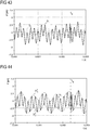
- Fig. 21 the time-dependent signal c, which during the dynamic loading of the SE (B) sample with the in FIGS. 11 and 12 shown sample geometry by means of in FIG. 1 NF-DMS 5 has been determined, wherein, for better orientation, the later determined point in time t q at which a change in the cross section of the bending sample 1 starts during the dynamic loading was plotted, wherein t q has been determined by means of an optical reference method.
- a time-dependent signal c can be removed, the frequency range b of the selected vibration mode pair with the 3L mode number 20 from 17009 Hz to 17955 Hz in the signal spectrum of the NF-DMS can be well detected.
- an IIR filter can first be applied to the NF-DMS signal c.
- the upper and lower limit of the frequency band of the digital filter was set at +/- 25 Hz by the FEM simulation (modal analysis) of the selected pair of vibration modes at a sample temperature of -40 ° C, ie it became a frequency band of 17009 Hz + / - 25 Hz or 17955 Hz +/- 25 Hz selected to be in the FIGS. 23 and 24 to produce respective (bandpass) filtrates.
- FIG. 23 the filtrate BP pre obtained for the filter boundaries around the first mode of vibration of the selected pair of vibration modes before the change in cross section (the dynamic load, undamaged sample)
- FIG. 24 the filtrate BP post obtained for the filter boundaries around the second mode of vibration of the selected mode pair after cross-section change (the dynamic load, damaged sample).
- FIG. 25 are represented (RMS of root mean square).
- the time t q * of onset of the change in the cross section of the sample as determined by the method of dynamic load testing can thus be determined from the first significant local minimum of the signal component RMS (BPpre) after the time of mode splitting.
- Fig. 27 shows one with the full-bridge DMS 4 according to FIG. 1 force signal F (t) recorded in parallel during dynamic loading.
- Fig. 28 shows a temporally higher resolution (enlarged) section of the force signal FIG. 27 near the time t q , where t q has been determined by means of an optical reference method.
- the two values t q and t q are very close to each other with a time difference of 7.5 ns, which corresponds to a proportion of the primary loading period of approx. 0.006 ⁇ .
- FIGS. 29 and 30 A resulting simulated signal behavior in the force signal F as a function of time is in the FIGS. 29 and 30 shown, where Fig. 30 shows a temporally higher resolution section.
- the FIG. 30 indicates a higher-frequency anomaly around or after the time t q .
- Original force signals are generally even more multifrequent and can be modulated / synthesized (electronic amplifier noise, white noise) especially at higher frequencies. For the sake of clarity, however, their presentation is omitted.
- the signals are typically filtered in a frequency-selective manner in the frequency range of a relevant pair of vibration modes.
- FIG. 31 shows a characteristic frequency spectrum for a dynamic low-blow three-point bending test, which consists of the in FIGS. 29, 30 shown force signal s was obtained by means of an FFT.
- f 1 is a resonance frequency of the unchecked sample (ie, the first vibration mode of the vibration mode pair) and f 2 is a resonance frequency of the tested sample (ie, the second vibration mode of the vibration mode pair).
- the amounts for f 1 and f 2 can be determined from the frequency spectrum of the measurement signal of the strain gauge full bridge itself, or from FEM simulation by means of modal analysis or by evaluating the hammer tests before and after the dynamic load test.
- the filter limits f u (lower cutoff frequency) and f o (upper cutoff frequency) for bandpass filtering can be determined as follows.
- the bandpass width b 2 is in a range of 1.1 * b 1 to 4 * b 1 , more typically in a range of 1.5 * b 1 to 2.5 * b 1 .
- B 2 2 * b 1 was chosen for the following analyzes.
- the bandpass filter range is typically selected symmetrically about the average of the peak frequencies f 1 , f 2 .
- the bandpass filtrate S BP of the force signal s generated with this bandpass filter is recorded in Fig. 33 shown.
- the amplitude drop to the (additionally drawn and to be determined) time tq of the occurrence of the beat or respectively at the time of the change in cross section of the sample is already clearly visible.
- an upper envelope H 1 and a lower envelope H 2 of the bandpass filter rate S BP are typically formed, which are shown in FIG Fig. 34 being represented.
- the envelope H 1 , H 2 can be approximated and / or smoothed, typically with a spline, resulting in the in Fig. 35 shown smoothed envelopes H * 1 , H * 2 leads.
- the time t q can then be calculated as the time at which a first significant drop in the differential dH g / dt is detected.
- the time t q is typically determined as the time at which the differential dH g / dt as a peak in the negative dF / dt - falls range, more precisely at the time at which dH g / dt the peak half value of the first negative dF / dt - peaks reached.
- a phase analysis may be performed (block 1422 in FIG Fig. 8 ).
- Fig. 38 shows a corresponding force signal S of an SE (B) sample which was generated by means of a simulation and the time t q of the onset of the cross-sectional change of the sample as a dashed line.
- Fig. 39 shows the force signal S in higher temporal resolution, in which a phase anomaly in the vicinity of the time t q is recognizable.
- Original force signals are typically more multifrequent and, above all, they can be modulated / synthesized with higher frequency (electronic amplifier noise, white noise). For clarity, their presentation is omitted.
- the (force) signals are typically filtered in a frequency-selective manner in the frequency range of a relevant pair of vibration modes.
- bandpass filtering first takes place, which can be calculated via a first low-pass filtering with subsequent subtraction of the low-pass filter rate from the force signal to generate a signal filtrate S F , as described in US Pat Fig. 40 will be shown.
- a second-order digital IIR low-pass filter with a cut-off frequency of 5% was filtered over the un-examined sample's resonant frequency (ie, the first mode of vibration of the pair of oscillations). Thereafter, to calculate the signal filtrate S F, a subtraction of the thus obtained low-pass filtrate from the original signal S was performed.
- the cut-off frequency of the low-pass filter is in a range of 1% to 10%, more typically in a range of 2% to 7% above the resonant frequency of the unchecked sample to be examined.
- a reference signal r is typically first generated with the resonance frequency of the unchecked sample and an exemplary amplitude 1 (see FIG Fig. 42 ) and this synchronized with the signal filtrate S F.
- Fig. 43 shows the signal filtrate S F and the synchronized reference signal r s .
- the determination of the phase shift ⁇ for the synchronization of the reference signal r with the signal filtrate S F is typically carried out by calculating the cross-correlation of these two signals in a time interval before the occurrence of the phase jump (initially approximated).
- the reference signal is then generated by temporal displacement by ⁇ to the left to the synchronized reference signal r s .
- first of all the amplitude response of the signal filtrate Sp can be determined.
- the smoothed envelopes H 1 * and H 2 * are now sign-selectively multiplied (convolved) with the synchronized reference signal Sp to produce the in Fig. 45 shown modulated and synchronized reference signal r Smod to calculate.
- t q a significant increase of the difference signal S D can be analyzed. This can be realized, for example, when a defined force threshold value is exceeded in the case of temporally retroactive correction of the thus determined value t q .
- an additionally recorded acceleration signal can be digitally filtered and evaluated.
- the loading device 6 of in FIG. 1 shown device for dynamic load testing additionally with an accelerometer (signal BA in Fig. 47 ) with a typical measuring range of up to approx. 1,000 g or even up to approx. 50,000 g.
- an accelerometer signal BA in Fig. 47
- the NF-DMS 5 used is typically read at a high sampling frequency of at least 1 MHz, or even 2 MHz, during the dynamic loading test.
- the signals S of the NF-DMS and BA of the accelerometer first to be synchronized. This can be done mathematically via the longitudinal sound velocities and corresponding lengths of the coupling members and / or experimentally. The latter will be explained below.
- the AF-DMS signal itself or the signal of a single strain gauge, a strain gauge half bridge or a strain gauge full bridge, which are respectively applied to the fin, the test punch or to the sample can be used.
- the time offset ⁇ t between the two signals can be determined from the difference of the first significant signal change of the signals BA and S (signal of a single strain gauge at the fin).
- the Figures 48 and 49 show, with different time resolution, the signal BA S of the acceleration sensor synchronized with the signal of a single strain gage on the fin obtained by subtracting the time channel values of the signal BA by the time offset ⁇ t. Again, the change time t q to be calculated is already indicated in each case.
- the synchronized signal BA S of the acceleration sensor can now be filtered with a threshold filter.
- the typically symmetric-to-zero filter thresholds of the threshold filter depend on the sample and the loading forces.
- the lower threshold was -4000 m / s 2 and the upper threshold was 4000 m / s 2 . It becomes clear at the threshold filtrate f SW a strong negative acceleration peak near the time of onset of the change in the cross section of the sample t q .
- the velocity v has at time t q at a higher temporal resolution in Fig. 52 clearly recognizable local minimum.
- the time of the cross-sectional change of the sample t q at the location of the local minimum of the falling velocity v calculated from the synchronized acceleration of the falling mass can be determined near (a few nanoseconds) the largest acceleration peak during the loading phase.
- a test method includes measuring and registering a time dependent signal during dynamic loading of a sample, wherein the time dependent signal is correlated with a shape change and / or a vibrational state of the sample, determining a filter parameter comprising numerically determining expected vibrational modes of the sample dynamic loading and expected modes of vibration of the sample after dynamic loading, and determining a point in time at which a cross-section change of the bend sample begins during the dynamic loading, comprising digital filtering of the time dependent signal using the filter parameter.
- determining the filter parameter comprises determining a vibration mode pair comprising a first expected vibration mode of the sample before the dynamic loading and a second expected vibration mode corresponding to the first expected vibration mode of the sample after the dynamic loading.
- a dynamic load test method includes measuring and registering a time dependent signal during dynamic loading of a bend sample to produce a change in cross section, wherein the time dependent signal is correlated to a strain change of the bend sample during dynamic loading.
- a vibration mode pair and / or a vibration mode change is determined.
- the oscillation mode pair comprises a first oscillation mode of the bending sample before the cross-sectional change and a second oscillation mode of the bending sample corresponding to the first oscillation mode and / or corresponding to the first oscillation mode after the cross-sectional change. Determining the vibration mode pair and / or the vibration mode change includes a respective modal analysis for the flexure sample before the dynamic loading and after the dynamic loading.
- the vibration mode pair and / or the vibration mode change are used to determine at least one filter parameter.
- a time is determined at which the cross-sectional change of the bend sample begins during dynamic loading. Determining the time includes filtering the time dependent signal using the at least one filter parameter, typically digital filtering the time dependent signal using the at least one filter parameter.
- the at least one filter parameter is typically a frequency (eg, two filter parameters defining a frequency range for (digital) filtering) near a frequency of the vibration mode pair (resonant frequency) and a mean frequency at which the vibration mode change (eg a resonance shift) occurs.
- the respective filter parameter may be a frequency in the range of 90% to 110% of the resonant frequency of the respective vibration mode.
- the frequency range defined by two filter parameters typically includes both the resonant frequency of the first mode of vibration and the resonant frequency of the second mode of vibration (the range of resonant displacement).
- the frequency range may be relatively narrow, for example, only up to 10% or even up to 2% larger than the range of the resonance shift, in particular at the bottom and top 200 Hz, maximum 100 Hz or even only 50 Hz maximum. This limits the (digital) filtering to the interesting area, which facilitates the subsequent analysis.
- the modal analyzes are done numerically, e.g. by means of a respective FEM simulation.
- the respective modal analysis can alternatively or additionally also be carried out experimentally.
- the method may include the steps of dynamically loading a flexure sample to produce a cross-sectional change, and measuring and registering a time-dependent signal during dynamic loading, wherein the time-dependent signal (c) is correlated to a strain of the flexure; Performing at least one experimental and at least one numerical, in particular a simulative modal analysis of the bend sample for determining a corresponding pair of vibration modes comprising a first characteristic vibration mode of the bending sample before the cross-sectional change and a second vibration mode of the bending sample corresponding to the first characteristic vibration mode after the cross-sectional change; Using the corresponding vibration mode pair to determine at least one filter parameter comprising digitally and / or analog filtering the time-dependent signal using the at least one filter parameter to determine a signal filtrate; and determining a point in time at which a cross-sectional change of the bend sample during the dynamic loading commences by evaluating the signal filtrate of the time-dependent signal.
- the cross-sectional change in dynamic loading includes cracking and / or crack growth.
- the method further comprises determining a force on the flexure at the time the cross-sectional change of the flexure test begins.
- the method further comprises determining a fracture mechanical material characteristic using the force acting on the flexure sample at the time the cross-sectional change of the flexure test commences.
Landscapes
- Physics & Mathematics (AREA)
- General Physics & Mathematics (AREA)
- Immunology (AREA)
- Life Sciences & Earth Sciences (AREA)
- Chemical & Material Sciences (AREA)
- Analytical Chemistry (AREA)
- Biochemistry (AREA)
- Health & Medical Sciences (AREA)
- Pathology (AREA)
- General Health & Medical Sciences (AREA)
- Acoustics & Sound (AREA)
- Engineering & Computer Science (AREA)
- Signal Processing (AREA)
- Mathematical Physics (AREA)
- Spectroscopy & Molecular Physics (AREA)
- Investigating Strength Of Materials By Application Of Mechanical Stress (AREA)
Applications Claiming Priority (1)
| Application Number | Priority Date | Filing Date | Title |
|---|---|---|---|
| DE102017112776.3A DE102017112776B4 (de) | 2017-06-09 | 2017-06-09 | Verfahren und Vorrichtung zur dynamischen Belastungsprüfung |
Publications (2)
| Publication Number | Publication Date |
|---|---|
| EP3413031A1 true EP3413031A1 (fr) | 2018-12-12 |
| EP3413031B1 EP3413031B1 (fr) | 2020-07-29 |
Family
ID=62186246
Family Applications (1)
| Application Number | Title | Priority Date | Filing Date |
|---|---|---|---|
| EP18172318.0A Active EP3413031B1 (fr) | 2017-06-09 | 2018-05-15 | Procédé et dispositif d'essai dynamique de charge |
Country Status (2)
| Country | Link |
|---|---|
| EP (1) | EP3413031B1 (fr) |
| DE (1) | DE102017112776B4 (fr) |
Cited By (1)
| Publication number | Priority date | Publication date | Assignee | Title |
|---|---|---|---|---|
| CN113188644A (zh) * | 2021-03-31 | 2021-07-30 | 大唐东营发电有限公司 | 一种旋转机械振动测试系统谐波振动幅值计算方法 |
Families Citing this family (1)
| Publication number | Priority date | Publication date | Assignee | Title |
|---|---|---|---|---|
| CN111964618B (zh) * | 2020-10-21 | 2021-01-29 | 上海建工集团股份有限公司 | 一种混凝土泵送管道壁厚检测设备及方法 |
Citations (2)
| Publication number | Priority date | Publication date | Assignee | Title |
|---|---|---|---|---|
| US4283956A (en) * | 1978-05-17 | 1981-08-18 | Motoren-Und Turbinen-Union | Method of detecting the onset of cracking in articles during dynamic testing |
| US4307610A (en) * | 1978-06-26 | 1981-12-29 | Swiss Aluminium Ltd. | Method for measuring crack propagation in samples, and a high frequency pulsator for carrying out the method |
Family Cites Families (3)
| Publication number | Priority date | Publication date | Assignee | Title |
|---|---|---|---|---|
| AT501082B8 (de) * | 2004-10-11 | 2007-02-15 | Hafellner Reinhard Dipl Ing | Verfahren und vorrichtung zur ermittlung mechanischer eigenschaften eines materials |
| DE102009053297A1 (de) * | 2009-11-16 | 2011-05-19 | Institut für Fertigteiltechnik und Fertigbau Weimar e.V. | Verfahren zur Bestimmung der vibrationstechnischen Eigenschaften von Unterlagsplatten in einer Umlaufanlage zur Herstellung von Betonwaren mittels Vibrationsverdichtung und Vorrichtung zur zerstörungsfreien Messung dynamischer Eigenschaften einer Unterlagsplatte |
| DE102014117650B4 (de) * | 2014-12-02 | 2020-12-31 | Dr. Ing. H.C. F. Porsche Aktiengesellschaft | Verfahren zur automatisierten Bestimmung einer dynamischen Steifigkeit eines Objekts |
-
2017
- 2017-06-09 DE DE102017112776.3A patent/DE102017112776B4/de active Active
-
2018
- 2018-05-15 EP EP18172318.0A patent/EP3413031B1/fr active Active
Patent Citations (2)
| Publication number | Priority date | Publication date | Assignee | Title |
|---|---|---|---|---|
| US4283956A (en) * | 1978-05-17 | 1981-08-18 | Motoren-Und Turbinen-Union | Method of detecting the onset of cracking in articles during dynamic testing |
| US4307610A (en) * | 1978-06-26 | 1981-12-29 | Swiss Aluminium Ltd. | Method for measuring crack propagation in samples, and a high frequency pulsator for carrying out the method |
Non-Patent Citations (1)
| Title |
|---|
| MATSUMOTO AI ET AL: "Three-dimensional Visualization of Dynamic Oscillation of Structural Components Using Inhomogeneous Wireless Sensors", PROCEDIA ENGINEERING, ELSEVIER, AMSTERDAM, NL, vol. 188, 9 May 2017 (2017-05-09), pages 102 - 109, XP085009649, ISSN: 1877-7058, DOI: 10.1016/J.PROENG.2017.04.462 * |
Cited By (1)
| Publication number | Priority date | Publication date | Assignee | Title |
|---|---|---|---|---|
| CN113188644A (zh) * | 2021-03-31 | 2021-07-30 | 大唐东营发电有限公司 | 一种旋转机械振动测试系统谐波振动幅值计算方法 |
Also Published As
| Publication number | Publication date |
|---|---|
| DE102017112776A1 (de) | 2018-12-13 |
| DE102017112776B4 (de) | 2022-07-07 |
| EP3413031B1 (fr) | 2020-07-29 |
Similar Documents
| Publication | Publication Date | Title |
|---|---|---|
| DE102005044008B4 (de) | Verfahren zur Prüfung eines Massendurchflußmeßgeräts | |
| DE112006003935B4 (de) | Materialprüfmaschine vom Eindringtyp, Prüfverfahren und Prüfprogrammprodukt | |
| CN105067239B (zh) | 基于扫频激励振动的梁裂纹故障检测装置及方法 | |
| DE112013001672B4 (de) | Verfahren und Vorrichtung zum Messen einer Dämpfung in einem Werkstück | |
| EP3413031B1 (fr) | Procédé et dispositif d'essai dynamique de charge | |
| DE102018102535B3 (de) | Temperaturmessung mittels der Impedanz eines Ultraschalltransducers | |
| DE102016117647A1 (de) | Verfahren zur Gewinnung von Daten zu einem Rotorblatt für eine Windenergieanlage | |
| DE102010023727A1 (de) | Verfahren zur schwingungsarmen optischen Kraftmessung, insbesondere auch bei hohen Temperaturen | |
| DE102012216514B4 (de) | Verfahren zur statistischen Qualitätssicherung bei einer Untersuchung von Stahlprodukten innerhalb einer Stahlklasse | |
| EP2317308B1 (fr) | Dispositif et procédé de contrôle de dommages sur un composant | |
| DE102019216784B3 (de) | Prüfvorrichtung und Verfahren zur Beurteilung des Geräuschverhaltens einer Baugruppe | |
| DE19910802A1 (de) | System zur Überwachung der dynamischen Biegeaktivitäten an der Werkzeugausrichtung/Schließhöhe innerhalb einer Preßmaschine | |
| EP3473997B1 (fr) | Procédé et dispositif d'essai dynamique de charge | |
| EP3356813B1 (fr) | Procédé permettant de déterminer la distribution granulométrique de granulés dans un flux de transport et dispositif de mesure | |
| CN108333061A (zh) | 一种测量应力松弛的系统及测量方法 | |
| DE19531858B4 (de) | Messverfahren für Abspannseile | |
| DE102010042170A1 (de) | Messsystem für Eigenfrequenzmessungen an Scheibenbremsbelägen | |
| DE102006043912B9 (de) | Pendelschlagwerk | |
| DE102021100466A1 (de) | Sensorelement und Sensorvorrichtung zum Erfassen eines axialen Längenausgleichs in einem Längenausgleichsfutter beim Bearbeiten eines Werkstücks mit einem Werkzeug | |
| DE10252875A1 (de) | Betriebsfestigkeitsprüfung von Bauteilen eines Kraftfahrzeuges | |
| DE10015027B4 (de) | Verfahren zur Ausfallerkennung von schwingenden Bauteilen | |
| DE3918835A1 (de) | Verfahren und vorrichtung zur ermittlung der dynamischen und statischen kenngroessen elastischer werkstoffe | |
| DE102014106701A1 (de) | Verfahren zur Bestimmung einer statischen Biegesteifigkeit eines Objekts aus dynamischen Beschleunigungsmessungen nach einer Schwingungsanregung des Objekts | |
| DE102022200334A1 (de) | Verfahren und Vorrichtung zum Kalibrieren einer MEMS-Vorrichtung, und MEMS-Vorrichtung | |
| DE10256310B4 (de) | Verfahren und System zur Auswertung von Pendelschlagversuchen |
Legal Events
| Date | Code | Title | Description |
|---|---|---|---|
| PUAI | Public reference made under article 153(3) epc to a published international application that has entered the european phase |
Free format text: ORIGINAL CODE: 0009012 |
|
| STAA | Information on the status of an ep patent application or granted ep patent |
Free format text: STATUS: THE APPLICATION HAS BEEN PUBLISHED |
|
| AK | Designated contracting states |
Kind code of ref document: A1 Designated state(s): AL AT BE BG CH CY CZ DE DK EE ES FI FR GB GR HR HU IE IS IT LI LT LU LV MC MK MT NL NO PL PT RO RS SE SI SK SM TR |
|
| AX | Request for extension of the european patent |
Extension state: BA ME |
|
| STAA | Information on the status of an ep patent application or granted ep patent |
Free format text: STATUS: REQUEST FOR EXAMINATION WAS MADE |
|
| 17P | Request for examination filed |
Effective date: 20190529 |
|
| RBV | Designated contracting states (corrected) |
Designated state(s): AL AT BE BG CH CY CZ DE DK EE ES FI FR GB GR HR HU IE IS IT LI LT LU LV MC MK MT NL NO PL PT RO RS SE SI SK SM TR |
|
| RIC1 | Information provided on ipc code assigned before grant |
Ipc: G01N 3/32 20060101AFI20200116BHEP Ipc: G01N 29/04 20060101ALI20200116BHEP |
|
| GRAP | Despatch of communication of intention to grant a patent |
Free format text: ORIGINAL CODE: EPIDOSNIGR1 |
|
| STAA | Information on the status of an ep patent application or granted ep patent |
Free format text: STATUS: GRANT OF PATENT IS INTENDED |
|
| INTG | Intention to grant announced |
Effective date: 20200227 |
|
| GRAS | Grant fee paid |
Free format text: ORIGINAL CODE: EPIDOSNIGR3 |
|
| GRAA | (expected) grant |
Free format text: ORIGINAL CODE: 0009210 |
|
| STAA | Information on the status of an ep patent application or granted ep patent |
Free format text: STATUS: THE PATENT HAS BEEN GRANTED |
|
| AK | Designated contracting states |
Kind code of ref document: B1 Designated state(s): AL AT BE BG CH CY CZ DE DK EE ES FI FR GB GR HR HU IE IS IT LI LT LU LV MC MK MT NL NO PL PT RO RS SE SI SK SM TR |
|
| REG | Reference to a national code |
Ref country code: CH Ref legal event code: EP |
|
| REG | Reference to a national code |
Ref country code: AT Ref legal event code: REF Ref document number: 1296354 Country of ref document: AT Kind code of ref document: T Effective date: 20200815 |
|
| REG | Reference to a national code |
Ref country code: IE Ref legal event code: FG4D Free format text: LANGUAGE OF EP DOCUMENT: GERMAN |
|
| REG | Reference to a national code |
Ref country code: DE Ref legal event code: R096 Ref document number: 502018001988 Country of ref document: DE |
|
| REG | Reference to a national code |
Ref country code: LT Ref legal event code: MG4D |
|
| REG | Reference to a national code |
Ref country code: NL Ref legal event code: MP Effective date: 20200729 |
|
| PG25 | Lapsed in a contracting state [announced via postgrant information from national office to epo] |
Ref country code: HR Free format text: LAPSE BECAUSE OF FAILURE TO SUBMIT A TRANSLATION OF THE DESCRIPTION OR TO PAY THE FEE WITHIN THE PRESCRIBED TIME-LIMIT Effective date: 20200729 Ref country code: LT Free format text: LAPSE BECAUSE OF FAILURE TO SUBMIT A TRANSLATION OF THE DESCRIPTION OR TO PAY THE FEE WITHIN THE PRESCRIBED TIME-LIMIT Effective date: 20200729 Ref country code: NO Free format text: LAPSE BECAUSE OF FAILURE TO SUBMIT A TRANSLATION OF THE DESCRIPTION OR TO PAY THE FEE WITHIN THE PRESCRIBED TIME-LIMIT Effective date: 20201029 Ref country code: FI Free format text: LAPSE BECAUSE OF FAILURE TO SUBMIT A TRANSLATION OF THE DESCRIPTION OR TO PAY THE FEE WITHIN THE PRESCRIBED TIME-LIMIT Effective date: 20200729 Ref country code: SE Free format text: LAPSE BECAUSE OF FAILURE TO SUBMIT A TRANSLATION OF THE DESCRIPTION OR TO PAY THE FEE WITHIN THE PRESCRIBED TIME-LIMIT Effective date: 20200729 Ref country code: PT Free format text: LAPSE BECAUSE OF FAILURE TO SUBMIT A TRANSLATION OF THE DESCRIPTION OR TO PAY THE FEE WITHIN THE PRESCRIBED TIME-LIMIT Effective date: 20201130 Ref country code: ES Free format text: LAPSE BECAUSE OF FAILURE TO SUBMIT A TRANSLATION OF THE DESCRIPTION OR TO PAY THE FEE WITHIN THE PRESCRIBED TIME-LIMIT Effective date: 20200729 Ref country code: GR Free format text: LAPSE BECAUSE OF FAILURE TO SUBMIT A TRANSLATION OF THE DESCRIPTION OR TO PAY THE FEE WITHIN THE PRESCRIBED TIME-LIMIT Effective date: 20201030 Ref country code: BG Free format text: LAPSE BECAUSE OF FAILURE TO SUBMIT A TRANSLATION OF THE DESCRIPTION OR TO PAY THE FEE WITHIN THE PRESCRIBED TIME-LIMIT Effective date: 20201029 |
|
| PG25 | Lapsed in a contracting state [announced via postgrant information from national office to epo] |
Ref country code: LV Free format text: LAPSE BECAUSE OF FAILURE TO SUBMIT A TRANSLATION OF THE DESCRIPTION OR TO PAY THE FEE WITHIN THE PRESCRIBED TIME-LIMIT Effective date: 20200729 Ref country code: RS Free format text: LAPSE BECAUSE OF FAILURE TO SUBMIT A TRANSLATION OF THE DESCRIPTION OR TO PAY THE FEE WITHIN THE PRESCRIBED TIME-LIMIT Effective date: 20200729 Ref country code: PL Free format text: LAPSE BECAUSE OF FAILURE TO SUBMIT A TRANSLATION OF THE DESCRIPTION OR TO PAY THE FEE WITHIN THE PRESCRIBED TIME-LIMIT Effective date: 20200729 Ref country code: IS Free format text: LAPSE BECAUSE OF FAILURE TO SUBMIT A TRANSLATION OF THE DESCRIPTION OR TO PAY THE FEE WITHIN THE PRESCRIBED TIME-LIMIT Effective date: 20201129 |
|
| PG25 | Lapsed in a contracting state [announced via postgrant information from national office to epo] |
Ref country code: NL Free format text: LAPSE BECAUSE OF FAILURE TO SUBMIT A TRANSLATION OF THE DESCRIPTION OR TO PAY THE FEE WITHIN THE PRESCRIBED TIME-LIMIT Effective date: 20200729 |
|
| PG25 | Lapsed in a contracting state [announced via postgrant information from national office to epo] |
Ref country code: IT Free format text: LAPSE BECAUSE OF FAILURE TO SUBMIT A TRANSLATION OF THE DESCRIPTION OR TO PAY THE FEE WITHIN THE PRESCRIBED TIME-LIMIT Effective date: 20200729 Ref country code: SM Free format text: LAPSE BECAUSE OF FAILURE TO SUBMIT A TRANSLATION OF THE DESCRIPTION OR TO PAY THE FEE WITHIN THE PRESCRIBED TIME-LIMIT Effective date: 20200729 Ref country code: EE Free format text: LAPSE BECAUSE OF FAILURE TO SUBMIT A TRANSLATION OF THE DESCRIPTION OR TO PAY THE FEE WITHIN THE PRESCRIBED TIME-LIMIT Effective date: 20200729 Ref country code: CZ Free format text: LAPSE BECAUSE OF FAILURE TO SUBMIT A TRANSLATION OF THE DESCRIPTION OR TO PAY THE FEE WITHIN THE PRESCRIBED TIME-LIMIT Effective date: 20200729 Ref country code: DK Free format text: LAPSE BECAUSE OF FAILURE TO SUBMIT A TRANSLATION OF THE DESCRIPTION OR TO PAY THE FEE WITHIN THE PRESCRIBED TIME-LIMIT Effective date: 20200729 Ref country code: RO Free format text: LAPSE BECAUSE OF FAILURE TO SUBMIT A TRANSLATION OF THE DESCRIPTION OR TO PAY THE FEE WITHIN THE PRESCRIBED TIME-LIMIT Effective date: 20200729 |
|
| REG | Reference to a national code |
Ref country code: DE Ref legal event code: R097 Ref document number: 502018001988 Country of ref document: DE |
|
| PG25 | Lapsed in a contracting state [announced via postgrant information from national office to epo] |
Ref country code: AL Free format text: LAPSE BECAUSE OF FAILURE TO SUBMIT A TRANSLATION OF THE DESCRIPTION OR TO PAY THE FEE WITHIN THE PRESCRIBED TIME-LIMIT Effective date: 20200729 |
|
| PLBE | No opposition filed within time limit |
Free format text: ORIGINAL CODE: 0009261 |
|
| STAA | Information on the status of an ep patent application or granted ep patent |
Free format text: STATUS: NO OPPOSITION FILED WITHIN TIME LIMIT |
|
| PG25 | Lapsed in a contracting state [announced via postgrant information from national office to epo] |
Ref country code: SK Free format text: LAPSE BECAUSE OF FAILURE TO SUBMIT A TRANSLATION OF THE DESCRIPTION OR TO PAY THE FEE WITHIN THE PRESCRIBED TIME-LIMIT Effective date: 20200729 |
|
| 26N | No opposition filed |
Effective date: 20210430 |
|
| PG25 | Lapsed in a contracting state [announced via postgrant information from national office to epo] |
Ref country code: SI Free format text: LAPSE BECAUSE OF FAILURE TO SUBMIT A TRANSLATION OF THE DESCRIPTION OR TO PAY THE FEE WITHIN THE PRESCRIBED TIME-LIMIT Effective date: 20200729 |
|
| REG | Reference to a national code |
Ref country code: DE Ref legal event code: R119 Ref document number: 502018001988 Country of ref document: DE |
|
| REG | Reference to a national code |
Ref country code: CH Ref legal event code: PL |
|
| PG25 | Lapsed in a contracting state [announced via postgrant information from national office to epo] |
Ref country code: CH Free format text: LAPSE BECAUSE OF NON-PAYMENT OF DUE FEES Effective date: 20210531 Ref country code: LI Free format text: LAPSE BECAUSE OF NON-PAYMENT OF DUE FEES Effective date: 20210531 Ref country code: LU Free format text: LAPSE BECAUSE OF NON-PAYMENT OF DUE FEES Effective date: 20210515 Ref country code: MC Free format text: LAPSE BECAUSE OF FAILURE TO SUBMIT A TRANSLATION OF THE DESCRIPTION OR TO PAY THE FEE WITHIN THE PRESCRIBED TIME-LIMIT Effective date: 20200729 |
|
| REG | Reference to a national code |
Ref country code: BE Ref legal event code: MM Effective date: 20210531 |
|
| PG25 | Lapsed in a contracting state [announced via postgrant information from national office to epo] |
Ref country code: IE Free format text: LAPSE BECAUSE OF NON-PAYMENT OF DUE FEES Effective date: 20210515 Ref country code: DE Free format text: LAPSE BECAUSE OF NON-PAYMENT OF DUE FEES Effective date: 20211201 |
|
| PG25 | Lapsed in a contracting state [announced via postgrant information from national office to epo] |
Ref country code: BE Free format text: LAPSE BECAUSE OF NON-PAYMENT OF DUE FEES Effective date: 20210531 |
|
| PG25 | Lapsed in a contracting state [announced via postgrant information from national office to epo] |
Ref country code: CY Free format text: LAPSE BECAUSE OF FAILURE TO SUBMIT A TRANSLATION OF THE DESCRIPTION OR TO PAY THE FEE WITHIN THE PRESCRIBED TIME-LIMIT Effective date: 20200729 |
|
| PG25 | Lapsed in a contracting state [announced via postgrant information from national office to epo] |
Ref country code: HU Free format text: LAPSE BECAUSE OF FAILURE TO SUBMIT A TRANSLATION OF THE DESCRIPTION OR TO PAY THE FEE WITHIN THE PRESCRIBED TIME-LIMIT; INVALID AB INITIO Effective date: 20180515 |
|
| PGFP | Annual fee paid to national office [announced via postgrant information from national office to epo] |
Ref country code: FR Payment date: 20230526 Year of fee payment: 6 |
|
| PGFP | Annual fee paid to national office [announced via postgrant information from national office to epo] |
Ref country code: AT Payment date: 20230522 Year of fee payment: 6 |
|
| PGFP | Annual fee paid to national office [announced via postgrant information from national office to epo] |
Ref country code: GB Payment date: 20230524 Year of fee payment: 6 |
|
| PG25 | Lapsed in a contracting state [announced via postgrant information from national office to epo] |
Ref country code: MK Free format text: LAPSE BECAUSE OF FAILURE TO SUBMIT A TRANSLATION OF THE DESCRIPTION OR TO PAY THE FEE WITHIN THE PRESCRIBED TIME-LIMIT Effective date: 20200729 |