EP3412905A1 - Diesel hp pump with debris collector - Google Patents
Diesel hp pump with debris collector Download PDFInfo
- Publication number
- EP3412905A1 EP3412905A1 EP18176371.5A EP18176371A EP3412905A1 EP 3412905 A1 EP3412905 A1 EP 3412905A1 EP 18176371 A EP18176371 A EP 18176371A EP 3412905 A1 EP3412905 A1 EP 3412905A1
- Authority
- EP
- European Patent Office
- Prior art keywords
- pump
- recess
- stem
- magnetic
- grid
- Prior art date
- Legal status (The legal status is an assumption and is not a legal conclusion. Google has not performed a legal analysis and makes no representation as to the accuracy of the status listed.)
- Granted
Links
Images
Classifications
-
- F—MECHANICAL ENGINEERING; LIGHTING; HEATING; WEAPONS; BLASTING
- F02—COMBUSTION ENGINES; HOT-GAS OR COMBUSTION-PRODUCT ENGINE PLANTS
- F02M—SUPPLYING COMBUSTION ENGINES IN GENERAL WITH COMBUSTIBLE MIXTURES OR CONSTITUENTS THEREOF
- F02M59/00—Pumps specially adapted for fuel-injection and not provided for in groups F02M39/00 -F02M57/00, e.g. rotary cylinder-block type of pumps
- F02M59/44—Details, components parts, or accessories not provided for in, or of interest apart from, the apparatus of groups F02M59/02 - F02M59/42; Pumps having transducers, e.g. to measure displacement of pump rack or piston
-
- F—MECHANICAL ENGINEERING; LIGHTING; HEATING; WEAPONS; BLASTING
- F02—COMBUSTION ENGINES; HOT-GAS OR COMBUSTION-PRODUCT ENGINE PLANTS
- F02M—SUPPLYING COMBUSTION ENGINES IN GENERAL WITH COMBUSTIBLE MIXTURES OR CONSTITUENTS THEREOF
- F02M59/00—Pumps specially adapted for fuel-injection and not provided for in groups F02M39/00 -F02M57/00, e.g. rotary cylinder-block type of pumps
-
- B—PERFORMING OPERATIONS; TRANSPORTING
- B03—SEPARATION OF SOLID MATERIALS USING LIQUIDS OR USING PNEUMATIC TABLES OR JIGS; MAGNETIC OR ELECTROSTATIC SEPARATION OF SOLID MATERIALS FROM SOLID MATERIALS OR FLUIDS; SEPARATION BY HIGH-VOLTAGE ELECTRIC FIELDS
- B03C—MAGNETIC OR ELECTROSTATIC SEPARATION OF SOLID MATERIALS FROM SOLID MATERIALS OR FLUIDS; SEPARATION BY HIGH-VOLTAGE ELECTRIC FIELDS
- B03C1/00—Magnetic separation
- B03C1/02—Magnetic separation acting directly on the substance being separated
- B03C1/28—Magnetic plugs and dipsticks
-
- F—MECHANICAL ENGINEERING; LIGHTING; HEATING; WEAPONS; BLASTING
- F02—COMBUSTION ENGINES; HOT-GAS OR COMBUSTION-PRODUCT ENGINE PLANTS
- F02M—SUPPLYING COMBUSTION ENGINES IN GENERAL WITH COMBUSTIBLE MIXTURES OR CONSTITUENTS THEREOF
- F02M37/00—Apparatus or systems for feeding liquid fuel from storage containers to carburettors or fuel-injection apparatus; Arrangements for purifying liquid fuel specially adapted for, or arranged on, internal-combustion engines
- F02M37/22—Arrangements for purifying liquid fuel specially adapted for, or arranged on, internal-combustion engines, e.g. arrangements in the feeding system
-
- B—PERFORMING OPERATIONS; TRANSPORTING
- B01—PHYSICAL OR CHEMICAL PROCESSES OR APPARATUS IN GENERAL
- B01D—SEPARATION
- B01D35/00—Filtering devices having features not specifically covered by groups B01D24/00 - B01D33/00, or for applications not specifically covered by groups B01D24/00 - B01D33/00; Auxiliary devices for filtration; Filter housing constructions
- B01D35/06—Filters making use of electricity or magnetism
-
- B—PERFORMING OPERATIONS; TRANSPORTING
- B03—SEPARATION OF SOLID MATERIALS USING LIQUIDS OR USING PNEUMATIC TABLES OR JIGS; MAGNETIC OR ELECTROSTATIC SEPARATION OF SOLID MATERIALS FROM SOLID MATERIALS OR FLUIDS; SEPARATION BY HIGH-VOLTAGE ELECTRIC FIELDS
- B03C—MAGNETIC OR ELECTROSTATIC SEPARATION OF SOLID MATERIALS FROM SOLID MATERIALS OR FLUIDS; SEPARATION BY HIGH-VOLTAGE ELECTRIC FIELDS
- B03C2201/00—Details of magnetic or electrostatic separation
- B03C2201/18—Magnetic separation whereby the particles are suspended in a liquid
-
- B—PERFORMING OPERATIONS; TRANSPORTING
- B03—SEPARATION OF SOLID MATERIALS USING LIQUIDS OR USING PNEUMATIC TABLES OR JIGS; MAGNETIC OR ELECTROSTATIC SEPARATION OF SOLID MATERIALS FROM SOLID MATERIALS OR FLUIDS; SEPARATION BY HIGH-VOLTAGE ELECTRIC FIELDS
- B03C—MAGNETIC OR ELECTROSTATIC SEPARATION OF SOLID MATERIALS FROM SOLID MATERIALS OR FLUIDS; SEPARATION BY HIGH-VOLTAGE ELECTRIC FIELDS
- B03C2201/00—Details of magnetic or electrostatic separation
- B03C2201/28—Parts being designed to be removed for cleaning purposes
-
- B—PERFORMING OPERATIONS; TRANSPORTING
- B03—SEPARATION OF SOLID MATERIALS USING LIQUIDS OR USING PNEUMATIC TABLES OR JIGS; MAGNETIC OR ELECTROSTATIC SEPARATION OF SOLID MATERIALS FROM SOLID MATERIALS OR FLUIDS; SEPARATION BY HIGH-VOLTAGE ELECTRIC FIELDS
- B03C—MAGNETIC OR ELECTROSTATIC SEPARATION OF SOLID MATERIALS FROM SOLID MATERIALS OR FLUIDS; SEPARATION BY HIGH-VOLTAGE ELECTRIC FIELDS
- B03C2201/00—Details of magnetic or electrostatic separation
- B03C2201/30—Details of magnetic or electrostatic separation for use in or with vehicles
-
- F—MECHANICAL ENGINEERING; LIGHTING; HEATING; WEAPONS; BLASTING
- F02—COMBUSTION ENGINES; HOT-GAS OR COMBUSTION-PRODUCT ENGINE PLANTS
- F02M—SUPPLYING COMBUSTION ENGINES IN GENERAL WITH COMBUSTIBLE MIXTURES OR CONSTITUENTS THEREOF
- F02M2200/00—Details of fuel-injection apparatus, not otherwise provided for
- F02M2200/27—Fuel-injection apparatus with filters
Definitions
- the present invention relates to a diesel high pressure pump provided with a debris collector.
- a diesel internal combustion engine provided with direct fuel injection equipment comprises a high pressure (HP) pump receiving low pressure fuel and compressing it to thousands of bars.
- HP high pressure
- said fuel carries debris or manufacturing burrs and, some of said particles are not stopped by the filters arranged on the flow lines of the equipment, either because of a smaller size than the filter mesh, or flowing via a bypass channel arranged to enable cold start when said mesh is clogged with wax.
- More efficient devices are required to prevent damages and, it is essential to remove such particles to prevent severe damages to the pump and other components of the injection equipment.
- a high pressure pump of a diesel fuel injection equipment of an internal combustion engine said pump having a housing with walls surrounding an inner space and being provided with an inner channel extending through said walls joining said inner space to a compression chamber, said inner channel comprising a recess.
- the HP pump further comprises a debris collector comprising a grid member and a magnetic member.
- Said recess comprises an inner portion extending along a main axis from said inner end to an annular shoulder face joining a larger outer portion, said outer portion ultimately opening in an external face of the housing, the grid member comprising a tubular portion at an end of which is formed a transverse annular collar, the tubular portion being inserted in said recess inner portion, the collar being arranged against said shoulder face.
- Said grid member may integrally comprise a holding structure defining said collar and at least one leg and, a grid partially overmoulded in said holding structure and defining said tubular portion.
- said grid has a mesh of about 100 ⁇ m.
- the magnetic member may comprise a head from which extends a cylindrical stem, the head sealingly closing said recess, the stem extending inside the recess.
- Said head may sealingly be tightened in the recess outer portion compressing the collar of the grid member against the shoulder face and, said stem axially extending in said tubular portion of the grid member.
- Said stem may be magnetic and adapted to attract, in use, metallic debris present in the fuel.
- the stem may be provided with a blind bore opening at one end on the outer face of the head and defining an axial hollow in which is arranged a magnetic piece.
- Said magnetic piece may be press-fitted or bonded or overmoulded inside said hollow.
- the invention further extends to a method to clean a diesel HP pump as defined in any of the preceding claims, the method comprising the following steps:
- Diesel internal combustion engines are fueled with a direct injection equipment in which a high pressure pump 10 pressurises and delivers fuel to injectors.
- a debris collector 12 adapted to retain particles and metallic debris that may cause severe damages to the pump is arranged in said pump.
- the HP pump 10 has a housing 14 with walls surrounding an inner space S in which a camshaft (not shown) cooperates with a piston cyclically varying as per a pumping cycle the volume of a compression chamber in which fuel enters via an inner channel 16 joining said inner space S to said compression chamber.
- the debris collector 12 is arranged in said inner channel 16.
- the inner channel 16 defines a large cylindrical recess 18, the fuel entry (arrow A1) from the inner space S being at an inner end 20 of said recess and, the fuel exit (arrow A2) extending from a lateral face 22 of the recess, this configuration defining a 90° angle of the path followed by the flow.
- the recess 18 opens at its inner end 20 in the inner space S and extends along a main axis X up to an opposite outer end 24 opening on an external face 26 of the housing 12. Between said inner 20 and outer 24 ends, the recess 18 extends in an inner cylindrical portion 28 widening via an annular shoulder face 30 in a larger outer cylindrical portion 32 threaded on its external face. As visible on figures, the lateral face 22 from which departs the fuel exit A2 is the lateral face of the recess inner portion 28.
- the recess differs in that in the first embodiment, the recess directly opens in the inner space S at its inner end 20 while, in the second embodiment the inner end 20 defines a transverse bottom face 34 at the center of which opens a narrower channel 36 joining the inner space S to the recess.
- the debris collector 12 is arranged in the recess 22 and it comprises a grid member 38 and a magnetic member 40.
- the grid member 38 is an integral component comprising a holding structure, typically molded in plastic, overmoulding a grid element, typically of nylon, and defining an axially X cylindrical tubular portion 42, inserted in the inner portion 28 of the recess defining with the lateral face 22 of the recess an annular gap G. At an end of said tubular portion, the grid member forms a transverse annular collar 44 extending in surface contact against the shoulder face 30 of the recess.
- a first O-ring 46 arranged close to the inner end 20 of the recess closes a fluid communication direct from the fuel entry A1 to the fuel exit A2 via said gap G.
- said O-ring 46 is radially compressed between an annular groove provided in the holding structure and an area of said lateral face 22 close to the opening of the inner end 20.
- the fuel is forced to flow inside said tubular portion 38 then to pass through the grid, said first O-ring 46 closing any bypass of the grid.
- the magnetic member 40 has a threaded head 48 from which axially extends an stem 50.
- the head 48 is complementary tightened in the outer portion 32 of the recess so it abuts the collar 44 and maintains it sandwiched between said head 48 and the shoulder face 30.
- the head 48 On its external face, opposite the stem, the head 48 is provided with tool engagement means, a female hexagon 52 being the example of the embodiments while other means such as a slit, a male polygon... is possible.
- the stem 50 is magnetic and it axially extends inside the grid member 38.
- said head and stem are integral made of magnetic steel and, in the second embodiment of figure 3 , the stem 50 is hollow, provided with a blind bore 54 opening on the external face of the head, the head and hollow stem being integrally moulded in plastic. Inside said blind bore 54 is press-fitted or bonded a magnetic piece 56.
- a second O-ring 58 is arranged between the head and said face of the recess outer portion.
- the fuel enters the recess 18 which is large enough to slow down and disturb the flow, said turbulent flow inside the grid member 38 being represented by the curved double line arrow A1-A2.
- Metallic debris are attracted and stick on the magnetic stem 50 while other particles are retained by the grid prior to pass through said grid, joining the annular gap G and then exiting A2 toward the compression chamber.
- the inner portion 28 of the recess has a length of about 40mm and a diameter of about 20mm.
- the grid has a mesh of about 100 ⁇ m. These dimensions are indicative and can be chosen larger or smaller depending on the overall flow capacity of the pump 10.
- the first embodiment described, figure 1 shows the recess 18 directly opening in the inner space S and the integral steel-made magnetic member 40 and, the second embodiment, figures 3 , 4, 5 shows the recess having a bottom face 34 with a magnetic member having a hollow stem and a magnetic piece 56.
- the alternatives consisting of having the recess of the first embodiment with the magnetic member of the second embodiment is possible as well as, having the recess of the second embodiment and the magnetic member of the first embodiment.
- the pump 10 comprises numerous metallic components and, at the end of the production line the pump is cleaned to remove burrs and other debris that may remain from the manufacturing operations. Said cleaning operation is done by flushing a large quantity of fluid through the pump.
- said cleaning operation 100 comprises the following steps: The diesel HP pump 10 is provided 110 and the grid member 38 is arranged 120 in the recess 18. Afterward, the recess 18 is closed and sealed 130 to prevent leaks. Said pump assembly is then arranged 140 in a specific cleaning machine where said pump is flushed 150 by having a large flow going through. At the end the grid member may be cleaned from any debris that have been retained.
- the closing and sealing step 130 may be performed with a special non-magnetic plug that is afterward replaced by the final magnetic member.
- the flushing operation may be performed without having the magnetic piece 56 in place, said magnetic piece 56 being arranged afterward.
Landscapes
- Engineering & Computer Science (AREA)
- Chemical & Material Sciences (AREA)
- Combustion & Propulsion (AREA)
- Mechanical Engineering (AREA)
- General Engineering & Computer Science (AREA)
- Fuel-Injection Apparatus (AREA)
Abstract
Description
- The present invention relates to a diesel high pressure pump provided with a debris collector.
- A diesel internal combustion engine provided with direct fuel injection equipment comprises a high pressure (HP) pump receiving low pressure fuel and compressing it to thousands of bars. Unfortunately, said fuel carries debris or manufacturing burrs and, some of said particles are not stopped by the filters arranged on the flow lines of the equipment, either because of a smaller size than the filter mesh, or flowing via a bypass channel arranged to enable cold start when said mesh is clogged with wax. More efficient devices are required to prevent damages and, it is essential to remove such particles to prevent severe damages to the pump and other components of the injection equipment.
- Accordingly, it is an object of the present invention to resolve the above mentioned problems in providing a high pressure pump of a diesel fuel injection equipment of an internal combustion engine, said pump having a housing with walls surrounding an inner space and being provided with an inner channel extending through said walls joining said inner space to a compression chamber, said inner channel comprising a recess. In use fuel enters from an inner end and exits via an opening in a lateral face, said inner end and opening defining a right angle and wherein, arranged in said recess, the HP pump further comprises a debris collector comprising a grid member and a magnetic member.
- Said recess comprises an inner portion extending along a main axis from said inner end to an annular shoulder face joining a larger outer portion, said outer portion ultimately opening in an external face of the housing, the grid member comprising a tubular portion at an end of which is formed a transverse annular collar, the tubular portion being inserted in said recess inner portion, the collar being arranged against said shoulder face.
- Said grid member may integrally comprise a holding structure defining said collar and at least one leg and, a grid partially overmoulded in said holding structure and defining said tubular portion.
- More precisely, said grid has a mesh of about 100 µm.
- The magnetic member may comprise a head from which extends a cylindrical stem, the head sealingly closing said recess, the stem extending inside the recess.
- Said head may sealingly be tightened in the recess outer portion compressing the collar of the grid member against the shoulder face and, said stem axially extending in said tubular portion of the grid member.
- Said stem may be magnetic and adapted to attract, in use, metallic debris present in the fuel.
- The stem may be provided with a blind bore opening at one end on the outer face of the head and defining an axial hollow in which is arranged a magnetic piece.
- Said magnetic piece may be press-fitted or bonded or overmoulded inside said hollow.
- The invention further extends to a method to clean a diesel HP pump as defined in any of the preceding claims, the method comprising the following steps:
- providing a HP pump and arranging the grid member,
- sealing the recess preventing any leaks,
- arranging the HP pump on a cleaning machine,
- flushing the pump by having a large fuel flow going through,
- sealing the recess with a non-magnetic plug that is used during the flushing step, said non-magnetic plug being afterward replaced by the final magnetic member.
- sealing the recess with the final plug and hollow stem assembly, said hollow stem being empty during the flushing step, the magnetic component being inserted in the hollow of the stem after the flushing step.
- The present invention is now described by way of example with reference to the accompanying drawings in which:
-
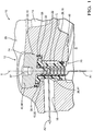
Figure 1 is a sectional view of part of a HP pump provided with a debris collector as per a first embodiment of the invention. -
Figure 2 is a 3D view of the debris collector offigure 1 . -
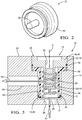
Figure 3 is similar tofigure 1 with a debris collector as per a second embodiment of the invention. -
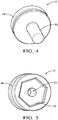
Figures 4 and 5 are 3D views of the debris collector offigure 3 . - Diesel internal combustion engines are fueled with a direct injection equipment in which a
high pressure pump 10 pressurises and delivers fuel to injectors. Adebris collector 12 adapted to retain particles and metallic debris that may cause severe damages to the pump is arranged in said pump. - More precisely, the HP
pump 10 has ahousing 14 with walls surrounding an inner space S in which a camshaft (not shown) cooperates with a piston cyclically varying as per a pumping cycle the volume of a compression chamber in which fuel enters via aninner channel 16 joining said inner space S to said compression chamber. Thedebris collector 12 is arranged in saidinner channel 16. - As shown on a first and a second embodiments respectively on
figures 1 and3 , theinner channel 16 defines a large cylindrical recess 18, the fuel entry (arrow A1) from the inner space S being at aninner end 20 of said recess and, the fuel exit (arrow A2) extending from alateral face 22 of the recess, this configuration defining a 90° angle of the path followed by the flow. - In details, the recess 18 opens at its
inner end 20 in the inner space S and extends along a main axis X up to an oppositeouter end 24 opening on anexternal face 26 of thehousing 12. Between said inner 20 and outer 24 ends, the recess 18 extends in an inner cylindrical portion 28 widening via anannular shoulder face 30 in a larger outer cylindrical portion 32 threaded on its external face. As visible on figures, thelateral face 22 from which departs the fuel exit A2 is the lateral face of the recess inner portion 28. - In said first and second embodiments the recess differs in that in the first embodiment, the recess directly opens in the inner space S at its
inner end 20 while, in the second embodiment theinner end 20 defines atransverse bottom face 34 at the center of which opens anarrower channel 36 joining the inner space S to the recess. - The
debris collector 12 is arranged in therecess 22 and it comprises agrid member 38 and a magnetic member 40. - The
grid member 38 is an integral component comprising a holding structure, typically molded in plastic, overmoulding a grid element, typically of nylon, and defining an axially X cylindrical tubular portion 42, inserted in the inner portion 28 of the recess defining with thelateral face 22 of the recess an annular gap G. At an end of said tubular portion, the grid member forms a transverse annular collar 44 extending in surface contact against theshoulder face 30 of the recess. A first O-ring 46 arranged close to theinner end 20 of the recess closes a fluid communication direct from the fuel entry A1 to the fuel exit A2 via said gap G. In the first embodiment offigure 1 and in the second embodiment offigure 3 said O-ring 46 is radially compressed between an annular groove provided in the holding structure and an area of saidlateral face 22 close to the opening of theinner end 20. In any case, the fuel is forced to flow inside saidtubular portion 38 then to pass through the grid, said first O-ring 46 closing any bypass of the grid. - The magnetic member 40 has a threaded
head 48 from which axially extends anstem 50. Thehead 48 is complementary tightened in the outer portion 32 of the recess so it abuts the collar 44 and maintains it sandwiched between saidhead 48 and theshoulder face 30. On its external face, opposite the stem, thehead 48 is provided with tool engagement means, afemale hexagon 52 being the example of the embodiments while other means such as a slit, a male polygon... is possible. Thestem 50 is magnetic and it axially extends inside thegrid member 38. - In the first embodiment of
figure 1 said head and stem are integral made of magnetic steel and, in the second embodiment offigure 3 , thestem 50 is hollow, provided with ablind bore 54 opening on the external face of the head, the head and hollow stem being integrally moulded in plastic. Inside saidblind bore 54 is press-fitted or bonded amagnetic piece 56. - To ensure sealing of the recess, a second O-
ring 58 is arranged between the head and said face of the recess outer portion. - In use, the fuel enters the recess 18 which is large enough to slow down and disturb the flow, said turbulent flow inside the
grid member 38 being represented by the curved double line arrow A1-A2. Metallic debris are attracted and stick on themagnetic stem 50 while other particles are retained by the grid prior to pass through said grid, joining the annular gap G and then exiting A2 toward the compression chamber. - Typically, the inner portion 28 of the recess has a length of about 40mm and a diameter of about 20mm. Also, the grid has a mesh of about 100µm. These dimensions are indicative and can be chosen larger or smaller depending on the overall flow capacity of the
pump 10. - The first embodiment described,
figure 1 , shows the recess 18 directly opening in the inner space S and the integral steel-made magnetic member 40 and, the second embodiment,figures 3 ,4, 5 shows the recess having abottom face 34 with a magnetic member having a hollow stem and amagnetic piece 56. The alternatives consisting of having the recess of the first embodiment with the magnetic member of the second embodiment is possible as well as, having the recess of the second embodiment and the magnetic member of the first embodiment. - The
pump 10 comprises numerous metallic components and, at the end of the production line the pump is cleaned to remove burrs and other debris that may remain from the manufacturing operations. Said cleaning operation is done by flushing a large quantity of fluid through the pump. - With the integral steel-made magnetic member,
figures 1 and2 , said cleaning operation 100 comprises the following steps:
The diesel HPpump 10 is provided 110 and thegrid member 38 is arranged 120 in the recess 18. Afterward, the recess 18 is closed and sealed 130 to prevent leaks. Said pump assembly is then arranged 140 in a specific cleaning machine where said pump is flushed 150 by having a large flow going through. At the end the grid member may be cleaned from any debris that have been retained. - More particularly, in the case of an integral steel-made magnetic member, the closing and sealing step 130 may be performed with a special non-magnetic plug that is afterward replaced by the final magnetic member. In the case of the second embodiment, the flushing operation may be performed without having the
magnetic piece 56 in place, saidmagnetic piece 56 being arranged afterward. -
- S
- inner space
- A1
- fuel entry
- A2
- fuel exit
- X
- main axis
- G
- annular gap
- 10
- high pressure pump
- 12
- debris collector
- 14
- housing
- 16
- inner channel
- 18
- recess
- 20
- inner end of the recess
- 22
- lateral face
- 24
- outer end of the recess
- 26
- external face of the pump housing
- 28
- inner portion of the recess
- 30
- shoulder face
- 32
- outer portion of the recess
- 34
- bottom face of the recess
- 36
- narrow channel
- 38
- grid member
- 40
- magnetic member
- 42
- tubular portion
- 44
- collar
- 46
- first O-ring
- 48
- head of the magnetic member
- 50
- stem of the magnetic member
- 52
- hexagon
- 54
- bore
- 56
- magnetic piece
- 58
- second O-ring
- 100
- method - cleaning operation
- 110
- providing
- 120
- arranging
- 130
- sealing
- 132
- sealing with a non-magnetic plug
- 134
- replacing
- 136
- inserting
- 140
- arranging
- 150
- flushing
Claims (10)
- High pressure pump (10) of a diesel fuel injection equipment of an internal combustion engine, said pump (10) having a housing (14) with walls surrounding an inner space (S) and being provided with an inner channel (16) extending through said walls joining said inner space (S) to a compression chamber, said inner channel (16) comprising a recess (18) wherein, in use fuel enters (A1) from an inner end (20) and exits (A2) via an opening in a lateral face (22), said inner end (20) and opening defining a right angle and wherein, arranged in said recess (18), the HP pump further comprises a debris collector (12) comprising a grid member (38) and a magnetic member (54) and wherein,
said recess (18) comprises an inner portion (28) extending along a main axis (X) from said inner end (20) to an annular shoulder face (30) joining a larger outer portion (32), said outer portion (32) ultimately opening in an external face (26) of the housing (14), the grid member (38) comprising a tubular portion (42) at an end of which is formed a transverse annular collar (44), the tubular portion (42) being inserted in said recess inner portion (28), the collar (44) being arranged against said shoulder face (30). - HP pump (10) as claimed in claim 1 wherein said grid member (38) integrally comprises a holding structure defining said collar (44) and at least one leg and, a grid partially overmoulded in said holding structure and defining said tubular portion (42).
- HP pump (10) as claimed in claim 2 wherein said grid has a mesh of about 100µm.
- HP pump (10) as claimed in any of the preceding claims wherein the magnetic member (40) comprises a head (48) from which extends a cylindrical stem (50), the head sealingly closing said recess, the stem extending inside the recess.
- HP pump (10) as claimed in claim 4 taken in combination with any of the claims 2 to 4, wherein said head is sealingly tightened in the recess outer portion (32) compressing the collar (44) of the grid member against the shoulder face (30) and, said stem (50) axially extending in said tubular portion of the grid member.
- HP pump (10) as claimed in claim 5 wherein said stem (50) is magnetic and adapted to attract, in use, metallic debris present in the fuel.
- HP pump (10) as claimed in claim 6 wherein the stem (50) is provided with a blind bore opening at one end on the outer face of the head and defining an axial hollow in which is arranged a magnetic piece (56).
- HP pump (10) as claimed in claim 7 wherein said magnetic piece (54) is press-fitted or bonded or overmoulded inside said hollow.
- Method (100) to clean a diesel HP pump (10) as claimed in any of the claims 4 to 6, the method comprising the following steps:- providing (110) a HP pump and arranging (120) the grid member,- sealing (130) the recess preventing any leaks,- arranging (140) the HP pump on a cleaning machine,- flushing (150) the pump by having a large fuel flow going through, and wherein, the sealing step (130) comprises:- sealing (132) the recess with a non-magnetic plug that is used during the flushing step, said non-magnetic plug being afterward replaced (134) by the final magnetic member.
- Method (100) as claimed in claim 9, the HP pump being as claimed in any of the claims 8 or 9, the sealing (130) step comprising:- sealing (130) the recess with the final plug and hollow stem assembly, said hollow stem being empty during the flushing step, the magnetic component being inserted (136) in the hollow of the stem after the flushing step.
Applications Claiming Priority (1)
| Application Number | Priority Date | Filing Date | Title |
|---|---|---|---|
| GB1709069.7A GB2563244A (en) | 2017-06-07 | 2017-06-07 | Diesel HP pump with debris collector |
Publications (2)
| Publication Number | Publication Date |
|---|---|
| EP3412905A1 true EP3412905A1 (en) | 2018-12-12 |
| EP3412905B1 EP3412905B1 (en) | 2021-12-15 |
Family
ID=59349776
Family Applications (1)
| Application Number | Title | Priority Date | Filing Date |
|---|---|---|---|
| EP18176371.5A Active EP3412905B1 (en) | 2017-06-07 | 2018-06-06 | Diesel hp pump with debris collector |
Country Status (2)
| Country | Link |
|---|---|
| EP (1) | EP3412905B1 (en) |
| GB (1) | GB2563244A (en) |
Families Citing this family (1)
| Publication number | Priority date | Publication date | Assignee | Title |
|---|---|---|---|---|
| DE102019122942B4 (en) * | 2019-08-27 | 2022-12-08 | Volkswagen Aktiengesellschaft | Fuel supply system with at least one magnetic device for detecting and retaining magnetic particles to protect the system and its components |
Citations (8)
| Publication number | Priority date | Publication date | Assignee | Title |
|---|---|---|---|---|
| US3841489A (en) * | 1973-05-02 | 1974-10-15 | Kuss R And Co Inc | Fluid filter |
| DE3231929A1 (en) * | 1982-08-27 | 1984-03-01 | Robert Bosch Gmbh, 7000 Stuttgart | Liquid filter |
| WO2002014680A1 (en) * | 2000-08-11 | 2002-02-21 | Siemens Aktiengesellschaft | Filter device for a high pressure area of a storage injection system for an internal combustion engine |
| DE102004054652A1 (en) * | 2004-11-11 | 2006-05-18 | Jung, Yoon-Sang, Goyang | Fuel injecting device for four cylinder diesel engine, has filter arranged in high pressure pipe between pump and accumulator, and magnet connected in flow path between pump and injectors |
| DE102010030165A1 (en) * | 2010-06-16 | 2011-12-22 | Robert Bosch Gmbh | Device for deposition of particles in fuel inlet, particularly low pressure inlet, of fuel injection system, has permanent magnet for deposition of magnetic particles, where strainer or filter element is provided |
| DE102011004274A1 (en) * | 2011-02-17 | 2012-08-23 | Robert Bosch Gmbh | Housing structure for e.g. high pressure pump in fuel injection system of internal combustion engine, has blind bore with collection point which is extended from widening portion at specific angle with respect to bore |
| EP2597295A2 (en) * | 2011-11-25 | 2013-05-29 | Andreas Stihl AG & Co. KG | Hand-operated implement and suction head for connecting with a fuel line in a hand-held work device |
| WO2017037631A1 (en) * | 2015-09-04 | 2017-03-09 | Uab "Auksto Slegio Filtravimo Sprendimai" | High-pressure liquid filter with support stem and application of this filter in fuel system |
Family Cites Families (4)
| Publication number | Priority date | Publication date | Assignee | Title |
|---|---|---|---|---|
| JPS59119315A (en) * | 1982-12-27 | 1984-07-10 | Fuji Elelctrochem Co Ltd | Optical isolator |
| DE29500218U1 (en) * | 1995-01-07 | 1995-03-02 | Bossert, Gerdi, 78052 Villingen-Schwenningen | Cleaning device for water pipes |
| JP2003062402A (en) * | 2001-06-20 | 2003-03-04 | Honda Motor Co Ltd | Oil cleaning system |
| ITUB201586596U1 (en) * | 2015-10-21 | 2017-04-21 | FILTER FOR THE TREATMENT OF A FLUID IN A PIPE, IN PARTICULAR OF A WATER NETWORK |
-
2017
- 2017-06-07 GB GB1709069.7A patent/GB2563244A/en not_active Withdrawn
-
2018
- 2018-06-06 EP EP18176371.5A patent/EP3412905B1/en active Active
Patent Citations (8)
| Publication number | Priority date | Publication date | Assignee | Title |
|---|---|---|---|---|
| US3841489A (en) * | 1973-05-02 | 1974-10-15 | Kuss R And Co Inc | Fluid filter |
| DE3231929A1 (en) * | 1982-08-27 | 1984-03-01 | Robert Bosch Gmbh, 7000 Stuttgart | Liquid filter |
| WO2002014680A1 (en) * | 2000-08-11 | 2002-02-21 | Siemens Aktiengesellschaft | Filter device for a high pressure area of a storage injection system for an internal combustion engine |
| DE102004054652A1 (en) * | 2004-11-11 | 2006-05-18 | Jung, Yoon-Sang, Goyang | Fuel injecting device for four cylinder diesel engine, has filter arranged in high pressure pipe between pump and accumulator, and magnet connected in flow path between pump and injectors |
| DE102010030165A1 (en) * | 2010-06-16 | 2011-12-22 | Robert Bosch Gmbh | Device for deposition of particles in fuel inlet, particularly low pressure inlet, of fuel injection system, has permanent magnet for deposition of magnetic particles, where strainer or filter element is provided |
| DE102011004274A1 (en) * | 2011-02-17 | 2012-08-23 | Robert Bosch Gmbh | Housing structure for e.g. high pressure pump in fuel injection system of internal combustion engine, has blind bore with collection point which is extended from widening portion at specific angle with respect to bore |
| EP2597295A2 (en) * | 2011-11-25 | 2013-05-29 | Andreas Stihl AG & Co. KG | Hand-operated implement and suction head for connecting with a fuel line in a hand-held work device |
| WO2017037631A1 (en) * | 2015-09-04 | 2017-03-09 | Uab "Auksto Slegio Filtravimo Sprendimai" | High-pressure liquid filter with support stem and application of this filter in fuel system |
Also Published As
| Publication number | Publication date |
|---|---|
| GB2563244A (en) | 2018-12-12 |
| GB201709069D0 (en) | 2017-07-19 |
| EP3412905B1 (en) | 2021-12-15 |
Similar Documents
| Publication | Publication Date | Title |
|---|---|---|
| EP1377747B1 (en) | Fuel injection valve with a filter bush | |
| KR101486726B1 (en) | Fuel injection system for an internal combustion engine | |
| KR102194371B1 (en) | High-pressure fuel pump for a fuel injection system | |
| EP3205873A1 (en) | High pressure fuel supply pump | |
| RU2572989C2 (en) | Filter for fluids, filter barrel and filter head | |
| EP2060777A1 (en) | Internal lower fuel injector filter | |
| KR102268867B1 (en) | high pressure diesel pump | |
| DE102012010980A1 (en) | System for exhaust aftertreatment in internal combustion engines | |
| EP3412905B1 (en) | Diesel hp pump with debris collector | |
| CN106795849A (en) | Pressure limiting valve | |
| JP2004518873A (en) | Fuel injection valve | |
| CN109072839B (en) | fuel inlet filter for fuel injector | |
| CN105283664B (en) | Fuel injection valve | |
| EP2396536B1 (en) | Injection valve | |
| JP7714053B2 (en) | Injector with integrated filter | |
| EP2884091A1 (en) | Fuel injector valve | |
| US20180010562A1 (en) | High-pressure pump and method for manufacturing same | |
| US20200173410A1 (en) | Filter for fuel injectors | |
| JP2007016699A (en) | High pressure fuel supply pump | |
| JP2013253566A (en) | Fuel injection device | |
| US20200208596A1 (en) | High pressure fuel pump | |
| EP2549094A2 (en) | An injection valve for internal combustion engines | |
| EP3322501B1 (en) | Filter adapter for a fuel injector | |
| DE102013225820A1 (en) | Fuel injector | |
| JP6220729B2 (en) | High pressure fuel supply pump, airtight test method and manufacturing method of high pressure fuel supply pump |
Legal Events
| Date | Code | Title | Description |
|---|---|---|---|
| STAA | Information on the status of an ep patent application or granted ep patent |
Free format text: STATUS: UNKNOWN |
|
| PUAI | Public reference made under article 153(3) epc to a published international application that has entered the european phase |
Free format text: ORIGINAL CODE: 0009012 |
|
| STAA | Information on the status of an ep patent application or granted ep patent |
Free format text: STATUS: THE APPLICATION HAS BEEN PUBLISHED |
|
| AK | Designated contracting states |
Kind code of ref document: A1 Designated state(s): AL AT BE BG CH CY CZ DE DK EE ES FI FR GB GR HR HU IE IS IT LI LT LU LV MC MK MT NL NO PL PT RO RS SE SI SK SM TR |
|
| AX | Request for extension of the european patent |
Extension state: BA ME |
|
| STAA | Information on the status of an ep patent application or granted ep patent |
Free format text: STATUS: REQUEST FOR EXAMINATION WAS MADE |
|
| 17P | Request for examination filed |
Effective date: 20190612 |
|
| RBV | Designated contracting states (corrected) |
Designated state(s): AL AT BE BG CH CY CZ DE DK EE ES FI FR GB GR HR HU IE IS IT LI LT LU LV MC MK MT NL NO PL PT RO RS SE SI SK SM TR |
|
| STAA | Information on the status of an ep patent application or granted ep patent |
Free format text: STATUS: EXAMINATION IS IN PROGRESS |
|
| 17Q | First examination report despatched |
Effective date: 20201207 |
|
| GRAP | Despatch of communication of intention to grant a patent |
Free format text: ORIGINAL CODE: EPIDOSNIGR1 |
|
| STAA | Information on the status of an ep patent application or granted ep patent |
Free format text: STATUS: GRANT OF PATENT IS INTENDED |
|
| INTG | Intention to grant announced |
Effective date: 20210707 |
|
| GRAS | Grant fee paid |
Free format text: ORIGINAL CODE: EPIDOSNIGR3 |
|
| GRAA | (expected) grant |
Free format text: ORIGINAL CODE: 0009210 |
|
| STAA | Information on the status of an ep patent application or granted ep patent |
Free format text: STATUS: THE PATENT HAS BEEN GRANTED |
|
| AK | Designated contracting states |
Kind code of ref document: B1 Designated state(s): AL AT BE BG CH CY CZ DE DK EE ES FI FR GB GR HR HU IE IS IT LI LT LU LV MC MK MT NL NO PL PT RO RS SE SI SK SM TR |
|
| REG | Reference to a national code |
Ref country code: GB Ref legal event code: FG4D Ref country code: CH Ref legal event code: EP |
|
| REG | Reference to a national code |
Ref country code: DE Ref legal event code: R096 Ref document number: 602018028094 Country of ref document: DE |
|
| REG | Reference to a national code |
Ref country code: IE Ref legal event code: FG4D |
|
| REG | Reference to a national code |
Ref country code: AT Ref legal event code: REF Ref document number: 1455666 Country of ref document: AT Kind code of ref document: T Effective date: 20220115 |
|
| RAP4 | Party data changed (patent owner data changed or rights of a patent transferred) |
Owner name: DELPHI TECHNOLOGIES IP LIMITED |
|
| REG | Reference to a national code |
Ref country code: LT Ref legal event code: MG9D |
|
| REG | Reference to a national code |
Ref country code: NL Ref legal event code: MP Effective date: 20211215 |
|
| PG25 | Lapsed in a contracting state [announced via postgrant information from national office to epo] |
Ref country code: RS Free format text: LAPSE BECAUSE OF FAILURE TO SUBMIT A TRANSLATION OF THE DESCRIPTION OR TO PAY THE FEE WITHIN THE PRESCRIBED TIME-LIMIT Effective date: 20211215 Ref country code: LT Free format text: LAPSE BECAUSE OF FAILURE TO SUBMIT A TRANSLATION OF THE DESCRIPTION OR TO PAY THE FEE WITHIN THE PRESCRIBED TIME-LIMIT Effective date: 20211215 Ref country code: FI Free format text: LAPSE BECAUSE OF FAILURE TO SUBMIT A TRANSLATION OF THE DESCRIPTION OR TO PAY THE FEE WITHIN THE PRESCRIBED TIME-LIMIT Effective date: 20211215 Ref country code: BG Free format text: LAPSE BECAUSE OF FAILURE TO SUBMIT A TRANSLATION OF THE DESCRIPTION OR TO PAY THE FEE WITHIN THE PRESCRIBED TIME-LIMIT Effective date: 20220315 |
|
| REG | Reference to a national code |
Ref country code: AT Ref legal event code: MK05 Ref document number: 1455666 Country of ref document: AT Kind code of ref document: T Effective date: 20211215 |
|
| PG25 | Lapsed in a contracting state [announced via postgrant information from national office to epo] |
Ref country code: SE Free format text: LAPSE BECAUSE OF FAILURE TO SUBMIT A TRANSLATION OF THE DESCRIPTION OR TO PAY THE FEE WITHIN THE PRESCRIBED TIME-LIMIT Effective date: 20211215 Ref country code: NO Free format text: LAPSE BECAUSE OF FAILURE TO SUBMIT A TRANSLATION OF THE DESCRIPTION OR TO PAY THE FEE WITHIN THE PRESCRIBED TIME-LIMIT Effective date: 20220315 Ref country code: LV Free format text: LAPSE BECAUSE OF FAILURE TO SUBMIT A TRANSLATION OF THE DESCRIPTION OR TO PAY THE FEE WITHIN THE PRESCRIBED TIME-LIMIT Effective date: 20211215 Ref country code: HR Free format text: LAPSE BECAUSE OF FAILURE TO SUBMIT A TRANSLATION OF THE DESCRIPTION OR TO PAY THE FEE WITHIN THE PRESCRIBED TIME-LIMIT Effective date: 20211215 Ref country code: GR Free format text: LAPSE BECAUSE OF FAILURE TO SUBMIT A TRANSLATION OF THE DESCRIPTION OR TO PAY THE FEE WITHIN THE PRESCRIBED TIME-LIMIT Effective date: 20220316 |
|
| PG25 | Lapsed in a contracting state [announced via postgrant information from national office to epo] |
Ref country code: NL Free format text: LAPSE BECAUSE OF FAILURE TO SUBMIT A TRANSLATION OF THE DESCRIPTION OR TO PAY THE FEE WITHIN THE PRESCRIBED TIME-LIMIT Effective date: 20211215 |
|
| PG25 | Lapsed in a contracting state [announced via postgrant information from national office to epo] |
Ref country code: SM Free format text: LAPSE BECAUSE OF FAILURE TO SUBMIT A TRANSLATION OF THE DESCRIPTION OR TO PAY THE FEE WITHIN THE PRESCRIBED TIME-LIMIT Effective date: 20211215 Ref country code: SK Free format text: LAPSE BECAUSE OF FAILURE TO SUBMIT A TRANSLATION OF THE DESCRIPTION OR TO PAY THE FEE WITHIN THE PRESCRIBED TIME-LIMIT Effective date: 20211215 Ref country code: RO Free format text: LAPSE BECAUSE OF FAILURE TO SUBMIT A TRANSLATION OF THE DESCRIPTION OR TO PAY THE FEE WITHIN THE PRESCRIBED TIME-LIMIT Effective date: 20211215 Ref country code: PT Free format text: LAPSE BECAUSE OF FAILURE TO SUBMIT A TRANSLATION OF THE DESCRIPTION OR TO PAY THE FEE WITHIN THE PRESCRIBED TIME-LIMIT Effective date: 20220418 Ref country code: ES Free format text: LAPSE BECAUSE OF FAILURE TO SUBMIT A TRANSLATION OF THE DESCRIPTION OR TO PAY THE FEE WITHIN THE PRESCRIBED TIME-LIMIT Effective date: 20211215 Ref country code: EE Free format text: LAPSE BECAUSE OF FAILURE TO SUBMIT A TRANSLATION OF THE DESCRIPTION OR TO PAY THE FEE WITHIN THE PRESCRIBED TIME-LIMIT Effective date: 20211215 Ref country code: CZ Free format text: LAPSE BECAUSE OF FAILURE TO SUBMIT A TRANSLATION OF THE DESCRIPTION OR TO PAY THE FEE WITHIN THE PRESCRIBED TIME-LIMIT Effective date: 20211215 |
|
| PG25 | Lapsed in a contracting state [announced via postgrant information from national office to epo] |
Ref country code: PL Free format text: LAPSE BECAUSE OF FAILURE TO SUBMIT A TRANSLATION OF THE DESCRIPTION OR TO PAY THE FEE WITHIN THE PRESCRIBED TIME-LIMIT Effective date: 20211215 Ref country code: AT Free format text: LAPSE BECAUSE OF FAILURE TO SUBMIT A TRANSLATION OF THE DESCRIPTION OR TO PAY THE FEE WITHIN THE PRESCRIBED TIME-LIMIT Effective date: 20211215 |
|
| REG | Reference to a national code |
Ref country code: DE Ref legal event code: R097 Ref document number: 602018028094 Country of ref document: DE |
|
| PG25 | Lapsed in a contracting state [announced via postgrant information from national office to epo] |
Ref country code: IS Free format text: LAPSE BECAUSE OF FAILURE TO SUBMIT A TRANSLATION OF THE DESCRIPTION OR TO PAY THE FEE WITHIN THE PRESCRIBED TIME-LIMIT Effective date: 20220415 |
|
| PLBE | No opposition filed within time limit |
Free format text: ORIGINAL CODE: 0009261 |
|
| STAA | Information on the status of an ep patent application or granted ep patent |
Free format text: STATUS: NO OPPOSITION FILED WITHIN TIME LIMIT |
|
| PG25 | Lapsed in a contracting state [announced via postgrant information from national office to epo] |
Ref country code: DK Free format text: LAPSE BECAUSE OF FAILURE TO SUBMIT A TRANSLATION OF THE DESCRIPTION OR TO PAY THE FEE WITHIN THE PRESCRIBED TIME-LIMIT Effective date: 20211215 Ref country code: AL Free format text: LAPSE BECAUSE OF FAILURE TO SUBMIT A TRANSLATION OF THE DESCRIPTION OR TO PAY THE FEE WITHIN THE PRESCRIBED TIME-LIMIT Effective date: 20211215 |
|
| 26N | No opposition filed |
Effective date: 20220916 |
|
| PG25 | Lapsed in a contracting state [announced via postgrant information from national office to epo] |
Ref country code: SI Free format text: LAPSE BECAUSE OF FAILURE TO SUBMIT A TRANSLATION OF THE DESCRIPTION OR TO PAY THE FEE WITHIN THE PRESCRIBED TIME-LIMIT Effective date: 20211215 |
|
| PG25 | Lapsed in a contracting state [announced via postgrant information from national office to epo] |
Ref country code: MC Free format text: LAPSE BECAUSE OF FAILURE TO SUBMIT A TRANSLATION OF THE DESCRIPTION OR TO PAY THE FEE WITHIN THE PRESCRIBED TIME-LIMIT Effective date: 20211215 |
|
| REG | Reference to a national code |
Ref country code: CH Ref legal event code: PL |
|
| REG | Reference to a national code |
Ref country code: BE Ref legal event code: MM Effective date: 20220630 |
|
| PG25 | Lapsed in a contracting state [announced via postgrant information from national office to epo] |
Ref country code: LU Free format text: LAPSE BECAUSE OF NON-PAYMENT OF DUE FEES Effective date: 20220606 Ref country code: LI Free format text: LAPSE BECAUSE OF NON-PAYMENT OF DUE FEES Effective date: 20220630 Ref country code: IE Free format text: LAPSE BECAUSE OF NON-PAYMENT OF DUE FEES Effective date: 20220606 Ref country code: CH Free format text: LAPSE BECAUSE OF NON-PAYMENT OF DUE FEES Effective date: 20220630 |
|
| PG25 | Lapsed in a contracting state [announced via postgrant information from national office to epo] |
Ref country code: IT Free format text: LAPSE BECAUSE OF FAILURE TO SUBMIT A TRANSLATION OF THE DESCRIPTION OR TO PAY THE FEE WITHIN THE PRESCRIBED TIME-LIMIT Effective date: 20211215 Ref country code: BE Free format text: LAPSE BECAUSE OF NON-PAYMENT OF DUE FEES Effective date: 20220630 |
|
| P01 | Opt-out of the competence of the unified patent court (upc) registered |
Effective date: 20230327 |
|
| PG25 | Lapsed in a contracting state [announced via postgrant information from national office to epo] |
Ref country code: HU Free format text: LAPSE BECAUSE OF FAILURE TO SUBMIT A TRANSLATION OF THE DESCRIPTION OR TO PAY THE FEE WITHIN THE PRESCRIBED TIME-LIMIT; INVALID AB INITIO Effective date: 20180606 |
|
| REG | Reference to a national code |
Ref country code: DE Ref legal event code: R081 Ref document number: 602018028094 Country of ref document: DE Owner name: PHINIA DELPHI LUXEMBOURG SARL, LU Free format text: FORMER OWNER: DELPHI TECHNOLOGIES IP LIMITED, SAINT MICHAEL, BB |
|
| PG25 | Lapsed in a contracting state [announced via postgrant information from national office to epo] |
Ref country code: MK Free format text: LAPSE BECAUSE OF FAILURE TO SUBMIT A TRANSLATION OF THE DESCRIPTION OR TO PAY THE FEE WITHIN THE PRESCRIBED TIME-LIMIT Effective date: 20211215 Ref country code: CY Free format text: LAPSE BECAUSE OF FAILURE TO SUBMIT A TRANSLATION OF THE DESCRIPTION OR TO PAY THE FEE WITHIN THE PRESCRIBED TIME-LIMIT Effective date: 20211215 |
|
| REG | Reference to a national code |
Ref country code: GB Ref legal event code: 732E Free format text: REGISTERED BETWEEN 20240725 AND 20240731 |
|
| PG25 | Lapsed in a contracting state [announced via postgrant information from national office to epo] |
Ref country code: MT Free format text: LAPSE BECAUSE OF FAILURE TO SUBMIT A TRANSLATION OF THE DESCRIPTION OR TO PAY THE FEE WITHIN THE PRESCRIBED TIME-LIMIT Effective date: 20211215 |
|
| PGFP | Annual fee paid to national office [announced via postgrant information from national office to epo] |
Ref country code: DE Payment date: 20250509 Year of fee payment: 8 |
|
| PGFP | Annual fee paid to national office [announced via postgrant information from national office to epo] |
Ref country code: GB Payment date: 20250508 Year of fee payment: 8 |
|
| PGFP | Annual fee paid to national office [announced via postgrant information from national office to epo] |
Ref country code: FR Payment date: 20250512 Year of fee payment: 8 |
|
| PG25 | Lapsed in a contracting state [announced via postgrant information from national office to epo] |
Ref country code: TR Free format text: LAPSE BECAUSE OF FAILURE TO SUBMIT A TRANSLATION OF THE DESCRIPTION OR TO PAY THE FEE WITHIN THE PRESCRIBED TIME-LIMIT Effective date: 20211215 |