EP2597295A2 - Hand-operated implement and suction head for connecting with a fuel line in a hand-held work device - Google Patents
Hand-operated implement and suction head for connecting with a fuel line in a hand-held work device Download PDFInfo
- Publication number
- EP2597295A2 EP2597295A2 EP12007680.7A EP12007680A EP2597295A2 EP 2597295 A2 EP2597295 A2 EP 2597295A2 EP 12007680 A EP12007680 A EP 12007680A EP 2597295 A2 EP2597295 A2 EP 2597295A2
- Authority
- EP
- European Patent Office
- Prior art keywords
- housing
- suction head
- weight body
- intermediate part
- magnet
- Prior art date
- Legal status (The legal status is an assumption and is not a legal conclusion. Google has not performed a legal analysis and makes no representation as to the accuracy of the status listed.)
- Granted
Links
- 239000000446 fuel Substances 0.000 title claims abstract description 47
- 239000002828 fuel tank Substances 0.000 claims abstract description 10
- 238000002485 combustion reaction Methods 0.000 claims abstract description 4
- 238000007789 sealing Methods 0.000 description 9
- 230000008719 thickening Effects 0.000 description 7
- 239000002184 metal Substances 0.000 description 6
- 239000000463 material Substances 0.000 description 5
- 210000002445 nipple Anatomy 0.000 description 4
- 238000004140 cleaning Methods 0.000 description 3
- 238000010276 construction Methods 0.000 description 2
- 238000004519 manufacturing process Methods 0.000 description 2
- 230000015572 biosynthetic process Effects 0.000 description 1
- 238000007664 blowing Methods 0.000 description 1
- 230000000694 effects Effects 0.000 description 1
- 238000000926 separation method Methods 0.000 description 1
- 230000006641 stabilisation Effects 0.000 description 1
- 238000011105 stabilization Methods 0.000 description 1
Images


Classifications
-
- F—MECHANICAL ENGINEERING; LIGHTING; HEATING; WEAPONS; BLASTING
- F02—COMBUSTION ENGINES; HOT-GAS OR COMBUSTION-PRODUCT ENGINE PLANTS
- F02M—SUPPLYING COMBUSTION ENGINES IN GENERAL WITH COMBUSTIBLE MIXTURES OR CONSTITUENTS THEREOF
- F02M37/00—Apparatus or systems for feeding liquid fuel from storage containers to carburettors or fuel-injection apparatus; Arrangements for purifying liquid fuel specially adapted for, or arranged on, internal-combustion engines
- F02M37/22—Arrangements for purifying liquid fuel specially adapted for, or arranged on, internal-combustion engines, e.g. arrangements in the feeding system
- F02M37/32—Arrangements for purifying liquid fuel specially adapted for, or arranged on, internal-combustion engines, e.g. arrangements in the feeding system characterised by filters or filter arrangements
- F02M37/52—Arrangements for purifying liquid fuel specially adapted for, or arranged on, internal-combustion engines, e.g. arrangements in the feeding system characterised by filters or filter arrangements using magnetic means
-
- B—PERFORMING OPERATIONS; TRANSPORTING
- B01—PHYSICAL OR CHEMICAL PROCESSES OR APPARATUS IN GENERAL
- B01D—SEPARATION
- B01D35/00—Filtering devices having features not specifically covered by groups B01D24/00 - B01D33/00, or for applications not specifically covered by groups B01D24/00 - B01D33/00; Auxiliary devices for filtration; Filter housing constructions
- B01D35/02—Filters adapted for location in special places, e.g. pipe-lines, pumps, stop-cocks
- B01D35/027—Filters adapted for location in special places, e.g. pipe-lines, pumps, stop-cocks rigidly mounted in or on tanks or reservoirs
-
- B—PERFORMING OPERATIONS; TRANSPORTING
- B01—PHYSICAL OR CHEMICAL PROCESSES OR APPARATUS IN GENERAL
- B01D—SEPARATION
- B01D35/00—Filtering devices having features not specifically covered by groups B01D24/00 - B01D33/00, or for applications not specifically covered by groups B01D24/00 - B01D33/00; Auxiliary devices for filtration; Filter housing constructions
- B01D35/06—Filters making use of electricity or magnetism
-
- F—MECHANICAL ENGINEERING; LIGHTING; HEATING; WEAPONS; BLASTING
- F02—COMBUSTION ENGINES; HOT-GAS OR COMBUSTION-PRODUCT ENGINE PLANTS
- F02M—SUPPLYING COMBUSTION ENGINES IN GENERAL WITH COMBUSTIBLE MIXTURES OR CONSTITUENTS THEREOF
- F02M27/00—Apparatus for treating combustion-air, fuel, or fuel-air mixture, by catalysts, electric means, magnetism, rays, sound waves, or the like
- F02M27/04—Apparatus for treating combustion-air, fuel, or fuel-air mixture, by catalysts, electric means, magnetism, rays, sound waves, or the like by electric means, ionisation, polarisation or magnetism
- F02M27/045—Apparatus for treating combustion-air, fuel, or fuel-air mixture, by catalysts, electric means, magnetism, rays, sound waves, or the like by electric means, ionisation, polarisation or magnetism by permanent magnets
-
- F—MECHANICAL ENGINEERING; LIGHTING; HEATING; WEAPONS; BLASTING
- F02—COMBUSTION ENGINES; HOT-GAS OR COMBUSTION-PRODUCT ENGINE PLANTS
- F02M—SUPPLYING COMBUSTION ENGINES IN GENERAL WITH COMBUSTIBLE MIXTURES OR CONSTITUENTS THEREOF
- F02M37/00—Apparatus or systems for feeding liquid fuel from storage containers to carburettors or fuel-injection apparatus; Arrangements for purifying liquid fuel specially adapted for, or arranged on, internal-combustion engines
- F02M37/0047—Layout or arrangement of systems for feeding fuel
- F02M37/007—Layout or arrangement of systems for feeding fuel characterised by its use in vehicles, in stationary plants or in small engines, e.g. hand held tools
-
- F—MECHANICAL ENGINEERING; LIGHTING; HEATING; WEAPONS; BLASTING
- F02—COMBUSTION ENGINES; HOT-GAS OR COMBUSTION-PRODUCT ENGINE PLANTS
- F02M—SUPPLYING COMBUSTION ENGINES IN GENERAL WITH COMBUSTIBLE MIXTURES OR CONSTITUENTS THEREOF
- F02M37/00—Apparatus or systems for feeding liquid fuel from storage containers to carburettors or fuel-injection apparatus; Arrangements for purifying liquid fuel specially adapted for, or arranged on, internal-combustion engines
- F02M37/22—Arrangements for purifying liquid fuel specially adapted for, or arranged on, internal-combustion engines, e.g. arrangements in the feeding system
- F02M37/32—Arrangements for purifying liquid fuel specially adapted for, or arranged on, internal-combustion engines, e.g. arrangements in the feeding system characterised by filters or filter arrangements
- F02M37/50—Filters arranged in or on fuel tanks
-
- F—MECHANICAL ENGINEERING; LIGHTING; HEATING; WEAPONS; BLASTING
- F02—COMBUSTION ENGINES; HOT-GAS OR COMBUSTION-PRODUCT ENGINE PLANTS
- F02M—SUPPLYING COMBUSTION ENGINES IN GENERAL WITH COMBUSTIBLE MIXTURES OR CONSTITUENTS THEREOF
- F02M69/00—Low-pressure fuel-injection apparatus ; Apparatus with both continuous and intermittent injection; Apparatus injecting different types of fuel
- F02M69/46—Details, component parts or accessories not provided for in, or of interest apart from, the apparatus covered by groups F02M69/02 - F02M69/44
- F02M69/52—Arrangement of fuel metering devices
-
- F—MECHANICAL ENGINEERING; LIGHTING; HEATING; WEAPONS; BLASTING
- F02—COMBUSTION ENGINES; HOT-GAS OR COMBUSTION-PRODUCT ENGINE PLANTS
- F02B—INTERNAL-COMBUSTION PISTON ENGINES; COMBUSTION ENGINES IN GENERAL
- F02B63/00—Adaptations of engines for driving pumps, hand-held tools or electric generators; Portable combinations of engines with engine-driven devices
- F02B63/02—Adaptations of engines for driving pumps, hand-held tools or electric generators; Portable combinations of engines with engine-driven devices for hand-held tools
-
- F—MECHANICAL ENGINEERING; LIGHTING; HEATING; WEAPONS; BLASTING
- F02—COMBUSTION ENGINES; HOT-GAS OR COMBUSTION-PRODUCT ENGINE PLANTS
- F02M—SUPPLYING COMBUSTION ENGINES IN GENERAL WITH COMBUSTIBLE MIXTURES OR CONSTITUENTS THEREOF
- F02M37/00—Apparatus or systems for feeding liquid fuel from storage containers to carburettors or fuel-injection apparatus; Arrangements for purifying liquid fuel specially adapted for, or arranged on, internal-combustion engines
- F02M37/22—Arrangements for purifying liquid fuel specially adapted for, or arranged on, internal-combustion engines, e.g. arrangements in the feeding system
- F02M37/32—Arrangements for purifying liquid fuel specially adapted for, or arranged on, internal-combustion engines, e.g. arrangements in the feeding system characterised by filters or filter arrangements
- F02M37/42—Installation or removal of filters
Definitions
- the invention relates to a hand-held implement with a fuel tank in which a suction head is arranged and a suction head for connection to a fuel line in a hand-held implement.
- a suction head for a fuel hose in a hand-held implement known.
- a weight body is arranged in the housing of the suction head.
- the fuel tank can, especially when filling the fuel tank, get dirt, which can also contain metal chips. These metal chips can in operation lead to a restriction of the fuel supply, in particular when the fuel is metered via an electromagnetic valve to which the metal chips can adhere.
- Such a magnet is usually made of metal and therefore has a comparatively high weight.
- the invention has for its object to provide a hand-held implement of the generic type, in which a good fuel cleaning is achieved with low weight.
- Another object of the invention is to provide a suction head for connection to provide with the fuel line in a hand-held implement, which achieves a good fuel cleaning with low weight.
- the suction head has at least two weight bodies.
- at least two of the weight bodies of the suction head, in particular all weight bodies of the suction head are formed at least partially as a magnet.
- at least one weight body, in particular all weight bodies is completely formed as a magnet.
- the suction head in particular has a lid on which an outlet opening for fuel is advantageously formed.
- the magnet is advantageously arranged on an intermediate part, which is arranged between the cover and a housing of the suction head.
- the lid holds the magnet, in particular at the intermediate part, so that a simple structure results.
- the magnet can be easily arranged on the intermediate part and fixed by the lid, so that there is a simple assembly of the suction head.
- the intermediate part is advantageously connected via a first connection to the housing and via a second connection to the cover.
- the first connection has first connection means on the housing and second connection means on the intermediate part, which cooperate when the intermediate part is arranged on the housing.
- the second connection advantageously has correspondingly third connecting means on the intermediate part and fourth connecting means on the cover, which cooperate when the cover is arranged on the intermediate part.
- the first connecting means are advantageously designed so that they both with the second connecting means and with the fourth Connecting means are connectable. This can be decided in the manufacture of the suction head, whether an intermediate part is arranged with magnet between the housing and the lid or not.
- the lid and the housing can be identical for both suction cups with magnet and suction cups without magnet. This results in a simple construction, and for the production of different suction heads only a few different components are needed.
- first connection and the second connection are designed as latching connections.
- the first and the second connection are advantageously detachable connections.
- a simple design results when the connecting means are each formed by a circumferential locking edge.
- the first and third connecting means are designed as an inner latching edge and the second and fourth connecting means are designed as an outer latching edge.
- the outer latching edge engages over the respective associated inner latching edge.
- it can also be provided on the cover an inner and on the housing an outer locking edge.
- the lid and the intermediate part at the respective side facing the housing with respect to their functional surfaces are the same. Sections that have no function can also be designed differently.
- the housing and the intermediate part are advantageously formed identically on the respective side facing the cover, the functional surfaces also being the same here. As a result, further functions taken over by the cover of a suction head without magnet and intermediate part, such as, for example, the fixing of a filter element, can be taken over by the intermediate part.
- the magnet is arranged between the cover and a housing of the suction head.
- an additional intermediate part can be omitted.
- the weight body of the suction head is completely formed as a magnet.
- the weight body may be formed, for example, in one piece and rod-shaped.
- a part of the weight body is formed as a magnetic, rod-shaped element is and a second, also magnetic part of the weight body is held in an intermediate part.
- the weight body may be arranged, in particular integrated, on the cover or on the housing of the suction head.
- the magnet can be clipped, cast or glued, for example.
- the housing advantageously has opposite to the lid a bottom on which the weight body is fixed.
- the weight body is formed in particular elongated, extending from the bottom of the housing into the housing interior and is at least partially flowed around by fuel.
- a weight body is then elongated when the extension parallel to the longitudinal center axis of the suction head is greater than the extension perpendicular to the longitudinal central axis.
- the weight body is in particular rod-shaped. In the formation of the weight body as a magnet thereby a good separation effect of metal chips is achieved.
- a simple structure results when the housing is made of plastic and the weight body is at least partially encapsulated in the material of the housing.
- the housing is at least partially cylindrical, wherein at least one inlet opening for fuel is formed on the circumference of the housing, which is covered by a sieve.
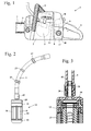
- Fig. 1 shows an embodiment of a hand-held implement a power saw 1.
- the invention is particularly advantageous for portable, hand-held implements that are moved and pivoted in operation, such as chainsaws, hedge trimmers, cutters, brushcutters, blowing devices or the like.
- the power saw 1 has a housing 2 on which a rear handle 3 and a handle tube 4 are arranged.
- an internal combustion engine 5 is arranged, which drives a saw chain 7 about a guide rail 6.
- a fuel tank 8 is integrated, in which a fuel line 9 opens, which is connected to a fuel supply device 10.
- a suction head 12 is fixed.
- the fuel line 9 may be integrally formed between the fuel supply device 10 and the suction head 12 and passed through the wall of the fuel tank 8. However, it can also be provided to form the fuel line 9 from a plurality of subsections, which are connected to one another, for example, in the region of the wall of the fuel tank.
- the fuel supply device 10 may be a carburetor, for example.
- the metering of the fuel may be due to the pressure prevailing in the intake passage 11 negative pressure or in addition via a valve, in particular an electromagnetic valve. However, it can also be provided to supply the fuel directly via a fuel valve, for example in a crankcase or an overflow channel of the internal combustion engine 5.
- the fuel line 9 is executed bent and has a plurality of thickening 23, which can serve for stabilization and positioning.
- the fuel line 9 is made of flexible material, such as rubber or plastic.
- the suction head 12 has a housing 13 which is substantially cylindrical and has a plurality of rectangular inlet openings 19, which are separated by longitudinal webs 36. The inlet openings 19 are each covered by a sieve 18, prevents the coarse dirt from entering the housing 13.
- an intermediate part 15 is arranged on the housing 13 and a cover 14 of the suction head 12.
- the free end 45 of the fuel line 9 is pushed.
- the cover 14 has on its side facing away from the housing 13 a connection nipple 20 with a circumferential rib 21, on which the fuel line 9 is pushed.
- connection nipple 20 At the connection nipple 20, an outlet opening 42 for fuel is formed, through which the fuel flows from the suction head 12 into the fuel line 9.
- the nipple 20 with the rib 21 is also in Fig. 4 shown.
- the rib 21 is formed on a cone, which widens toward the cover 14, so that the fuel line 9 can be slightly pushed onto the connecting nipple 20, but can only be removed with an increased expenditure of force.
- Fig. 5 shows the structure of the suction head 12 in detail.
- the housing 13 is cylindrical to a longitudinal central axis 48 of the suction head 12 and closed on its side facing away from the lid 14 of a bottom 35.
- the sieve 18 ( Fig. 4 ) is cast on the longitudinal webs 36 of the housing 13.
- the housing 13 is made of plastic.
- a first weight body 17 is arranged, which consists of a material of high density, preferably of metal, lead or the like.
- an element is referred to, which consists of a material whose density is greater than the density of the housing.
- the weight body 17 is approximately rod-shaped and elongated and has a foot 24, on which the weight body 17 is formed widened.
- the foot 24 is cast at the bottom 35 in the material of the housing 13.
- a circumferential lower positioning web 37 projects into the housing 13, against which a cylindrical filter element 22 sealingly abuts.
- the weight body 17 protrudes into the interior of the filter element 22.
- the longitudinal webs 36 support the filter element 22 on its outer side. Between the screen 18 and the filter element 22, a distance is formed, which is bridged by the longitudinal webs 36 substantially.
- the first weight body 17 extends over a large part of the However, the measured parallel to the longitudinal central axis 48 height of the housing 13, but does not project into the intermediate part 15.
- the first weight body 17 may, however, also extend to the intermediate part 15 or through the intermediate part 15 to the cover 14.
- the housing 13 has on its the intermediate part 15 side facing an inner locking edge 26 which is overlapped by an outer locking edge 27 of the intermediate part 15.
- the outer locking edge 27 engages with a thickening 50 in a circumferential groove 28 on the housing 13 and engages behind a thickening 49 on the inner locking edge 26.
- the thickening 49 and 50 are formed as circumferential, bead-shaped elevations.
- the inner latching edge 26 and the outer latching edge 27 form a first connection 25, which is designed as a latching connection.
- the intermediate part 15 has on its side facing the filter element 22 an upper sealing web 38, which is also formed circumferentially and the filter element 22 sealingly holds on its the intermediate part 17 facing side and positioned.
- the intermediate part 15 has a central opening 43, which extends the opening formed in the interior of the filter element 22 and can flow through the fuel.
- the intermediate part 15 also has an annular web 29 which projects into the gap formed between the housing 13 and the filter element 22 and thus positions the filter element 22 perpendicular to the longitudinal central axis 48.
- the intermediate part is disk-shaped, wherein the latching edges 27 and 31, the annular web 29 and the sealing web 38 protrude from the disk.
- a receptacle 41 for a second weight body 16 is formed, which is designed as a magnet.
- the second weight body 16 is disk-shaped and has a central opening 44 which is approximately the same size as the opening 43, so that the interior of the filter element 22 with the openings 43 and 44 forms a continuous channel for fuel.
- the intermediate part 15 has an inner latching edge 31, which is overlapped by an outer latching edge 32.
- the outer locking edge 32 engages with a thickening 52 in a groove 33 of the intermediate part 15 and thus fixes the lid 14 positively on the intermediate part 15.
- the thickening 52 engages behind a thickening 51 on the inner locking edge 31.
- the inner locking edge 31 forms with the outer Rastrand 32 a second connection 30, which is designed as a latching connection and which is identical to the first latching connection 25.
- the inner latching edge 31 of the intermediate part 15 is formed identically to the inner latching edge 26 of the housing 13, and the outer latching edge 32 of the cover 14 is identical to the outer latching edge 27 of the intermediate part 15.
- annular web 34 On the lid 14, a turned into the interior of the suction head 12 annular web 34 is formed, which engages in the inner locking edge 31 of the intermediate part 15 and secures the second weight body 16 in the direction of the longitudinal central axis 48. In the circumferential direction of the second weight body 16 is positively held in the receptacle 41.
- a sealing web 39 is also formed, which is identical to the sealing web 38 of the intermediate part 15.
- the sealing ridge 39 on the lid 14 has no function at the suction head 12.
- the inner and outer locking edges 26, 27, 31, 32, the annular webs 29, 34 and the sealing webs 38, 39 are functional surfaces.
- the intermediate part 15 is identical to the cover 14 in the function-relevant elements, ie the functional surfaces, on the side facing the housing 13 and identical to the housing 13 on the side facing the cover 14.
- the designed as a magnet second weight body is held at an intermediate part 15 which is formed on the side facing the housing 13 identical to the housing 13 facing side of the lid 14 and on the lid 14 side facing identical to the lid 14 facing side of the housing 13, the lid 14 can also be fixed directly to the housing 13.
- the intermediate part 15 with the second weight body 16 can also be omitted in implements in which no magnetic cleaning of the fuel is provided or expedient.
- the designed as a magnet second weight body 16 only the intermediate part 15 is required.
- the other elements of the suction head 12 can remain unchanged. It may be provided, in addition to the weight body 16 and the weight body 17 completely or partially form a magnet.
- Fig. 6 shows an embodiment of a suction head 46, which has a lid 14 and a housing 13.
- the lid 14 is attached directly to the housing 13.
- the suction head 46 has a weight body 47 which is completely formed as a magnet.
- the shape of the Weight body 47 corresponds to that of the first weight body 17.
- the other elements of the suction head 46 which are denoted by the same reference numerals as in Fig. 2 to 5 are designated correspond to these elements.
- the lid 14 is locked with its outer locking edge 32 on the inner locking edge 26 of the housing 13.
- the annular rib 34 protrudes into the intermediate space between the filter element 22 and the housing 13 and fixes the filter element 22 perpendicular to the longitudinal central axis 48.
- the sealing of the filter element 22 on the lid 14 takes place via the sealing web 39 formed on the lid 14.
- Fig. 7 shows a further embodiment of a suction head 56.
- the suction head 56 has a housing 53 which is closed by a cover 14. Inside the housing 53, a weight body 57 is arranged, which corresponds to the in Fig. 6 shown weight body 47 corresponds.
- the housing 53 corresponds in its construction essentially to the housing 13 described in the preceding figures. Like reference numerals designate corresponding elements in all figures.
- the housing 53 has on its lid 14 facing region an inner locking edge 54 which engages on the outer locking edge 32 of the lid 14.
- On the front side of the latching edge 54 is located on a second weight body 57, which is formed as an annular magnet. The second weight body 57 is held between the lid 14 and the housing 53, in particular clamped.
- the second weight body 57 is arranged outside of the annular web 34.
- the filter element 22 extends within the annular ridge 34 to the lid 14.
- the in Fig. 7 Ratchet 58 shown in dashed lines be provided, behind which the second weight body 57 is clipped. As a result, the second weight body 57 is held on the cover 14.
- the suction head 66 has a housing 13 which corresponds to the housing 13 shown in the preceding figures, and a lid 64 which is fixed to the housing 13 via a latching connection. Between the lid 64 and the filter element 22, the second weight body 67 is arranged adjacent to the end face of the filter element 22.
- the second weight body 67 has a circumferential, approximately triangular in cross-section sealing ridge 69, the Filter element sealingly fixed.
- the second weight body 67 is disposed on the lid 64 within a ring land 65.
- the annular web 65 has a latching edge 68, which is radially inwardly oriented relative to the longitudinal center axis 48, behind which the second weight body 67 is latched.
- the second weight body 67 is completely formed as a magnet.
- the second weight body 57, 67 between the lid 14, 64 and the housing 13, 53 may be omitted an additional intermediate part 15 for fixing the magnet.
- the weight body 57, 67 may also be cast or glued to the lid 14, 64.
- the first weight body 17, 47 may be glued to the housing 13, 53, clipped or, as shown in the figures, be cast.
- the first weight body 17, 47 may also extend to the lid 14, 64 and be clamped between the housing 13, 53 and the lid 14, 64.
Landscapes
- Engineering & Computer Science (AREA)
- Chemical & Material Sciences (AREA)
- Combustion & Propulsion (AREA)
- Mechanical Engineering (AREA)
- General Engineering & Computer Science (AREA)
- Chemical Kinetics & Catalysis (AREA)
- Water Supply & Treatment (AREA)
- Portable Nailing Machines And Staplers (AREA)
- Cooling, Air Intake And Gas Exhaust, And Fuel Tank Arrangements In Propulsion Units (AREA)
- Filtration Of Liquid (AREA)
- Scissors And Nippers (AREA)
Abstract
Description
Die Erfindung betrifft ein handgeführtes Arbeitsgerät mit einem Kraftstofftank, in dem ein Saugkopf angeordnet ist und einen Saugkopf zur Verbindung mit einer Kraftstoffleitung in einem handgeführten Arbeitsgerät.The invention relates to a hand-held implement with a fuel tank in which a suction head is arranged and a suction head for connection to a fuel line in a hand-held implement.
Aus der
In den Kraftstofftank können, insbesondere beim Befüllen des Kraftstofftanks, Verschmutzungen gelangen, die auch Metallspäne enthalten können. Diese Metallspäne können im Betrieb zu einer Behinderung der Kraftstoffzufuhr führen, und zwar insbesondere dann, wenn der Kraftstoff über ein elektromagnetisches Ventil dosiert wird, an dem die Metallspäne haften können.In the fuel tank can, especially when filling the fuel tank, get dirt, which can also contain metal chips. These metal chips can in operation lead to a restriction of the fuel supply, in particular when the fuel is metered via an electromagnetic valve to which the metal chips can adhere.
Es ist bekannt, in Kraftstofffiltern einen Magneten anzuordnen. Ein solcher Magnet besteht üblicherweise aus Metall und besitzt deshalb ein vergleichsweise hohes Gewicht.It is known to arrange a magnet in fuel filters. Such a magnet is usually made of metal and therefore has a comparatively high weight.
In handgeführten Arbeitsgeräten ist ein hohes Gewicht unerwünscht.In hand-held implements high weight is undesirable.
Der Erfindung liegt die Aufgabe zugrunde, ein handgeführtes Arbeitsgerät der gattungsgemäßen Art zu schaffen, bei dem eine gute Kraftstoffreinigung bei geringem Gewicht erzielt wird. Eine weitere Aufgabe der Erfindung liegt darin, einen Saugkopf zur Verbindung mit der Kraftstoffleitung in einem handgeführten Arbeitsgerät zu schaffen, der eine gute Kraftstoffreinigung bei geringem Gewicht erzielt.The invention has for its object to provide a hand-held implement of the generic type, in which a good fuel cleaning is achieved with low weight. Another object of the invention is to provide a suction head for connection to provide with the fuel line in a hand-held implement, which achieves a good fuel cleaning with low weight.
Diese Aufgabe wird bezüglich des Arbeitsgeräts durch ein handgeführtes Arbeitsgerät mit den Merkmalen des Anspruchs 1 und bezüglich des Saugkopfs durch einen Saugkopf mit den Merkmalen des Anspruchs 15 gelöst.This object is achieved with respect to the implement by a hand-held implement with the features of claim 1 and with respect to the suction head by a suction head with the features of
Es ist vorgesehen, den ohnehin vorhandenen Gewichtskörper mindestens teilweise als Magnet auszubilden. Dadurch kann ein zusätzlicher, das Gewicht des Arbeitsgeräts erhöhender Magnet entfallen.It is intended to form the already existing weight body at least partially as a magnet. As a result, an additional, the weight of the implement increasing magnet omitted.
Vorteilhaft besitzt der Saugkopf mindestens zwei Gewichtskörper. Insbesondere sind mindestens zwei der Gewichtskörper des Saugkopfs, insbesondere alle Gewichtskörper des Saugkopfs, mindestens teilweise als Magnet ausgebildet. Vorteilhaft ist mindestens ein Gewichtskörper, insbesondere alle Gewichtskörper, vollständig als Magnet ausgebildet.Advantageously, the suction head has at least two weight bodies. In particular, at least two of the weight bodies of the suction head, in particular all weight bodies of the suction head, are formed at least partially as a magnet. Advantageously, at least one weight body, in particular all weight bodies, is completely formed as a magnet.
Der Saugkopf besitzt insbesondere einen Deckel, an dem vorteilhaft eine Austrittsöffnung für Kraftstoff ausgebildet ist. Der Magnet ist vorteilhaft an einem Zwischenteil angeordnet, das zwischen dem Deckel und einem Gehäuse des Saugkopfs angeordnet ist. Dabei hält der Deckel den Magnet insbesondere an dem Zwischenteil, so dass sich ein einfacher Aufbau ergibt. Der Magnet kann auf einfache Weise an dem Zwischenteil angeordnet und durch den Deckel fixiert werden, so dass sich eine einfache Montage des Saugkopfs ergibt.The suction head in particular has a lid on which an outlet opening for fuel is advantageously formed. The magnet is advantageously arranged on an intermediate part, which is arranged between the cover and a housing of the suction head. In this case, the lid holds the magnet, in particular at the intermediate part, so that a simple structure results. The magnet can be easily arranged on the intermediate part and fixed by the lid, so that there is a simple assembly of the suction head.
Das Zwischenteil ist vorteilhaft über eine erste Verbindung mit dem Gehäuse und über eine zweite Verbindung mit dem Deckel verbunden. Vorteilhaft besitzt die erste Verbindung erste Verbindungsmittel am Gehäuse und zweite Verbindungsmittel am Zwischenteil, die zusammenwirken, wenn das Zwischenteil am Gehäuse angeordnet ist. Die zweite Verbindung besitzt vorteilhaft entsprechend dritte Verbindungsmittel am Zwischenteil und vierte Verbindungsmittel am Deckel, die zusammenwirken, wenn der Deckel am Zwischenteil angeordnet ist. Die ersten Verbindungsmittel sind vorteilhaft so ausgebildet, dass sie sowohl mit den zweiten Verbindungsmitteln als auch mit den vierten Verbindungsmitteln verbindbar sind. Dadurch kann bei der Herstellung des Saugkopfs entschieden werden, ob ein Zwischenteil mit Magnet zwischen Gehäuse und Deckel angeordnet wird oder nicht. Der Deckel und das Gehäuse können sowohl für Saugköpfe mit Magnet als auch für Saugköpfe ohne Magnet identisch ausgebildet sein. Dadurch ergibt sich ein einfacher Aufbau, und für die Herstellung unterschiedlicher Saugköpfe werden nur wenige unterschiedliche Bauteile benötigt.The intermediate part is advantageously connected via a first connection to the housing and via a second connection to the cover. Advantageously, the first connection has first connection means on the housing and second connection means on the intermediate part, which cooperate when the intermediate part is arranged on the housing. The second connection advantageously has correspondingly third connecting means on the intermediate part and fourth connecting means on the cover, which cooperate when the cover is arranged on the intermediate part. The first connecting means are advantageously designed so that they both with the second connecting means and with the fourth Connecting means are connectable. This can be decided in the manufacture of the suction head, whether an intermediate part is arranged with magnet between the housing and the lid or not. The lid and the housing can be identical for both suction cups with magnet and suction cups without magnet. This results in a simple construction, and for the production of different suction heads only a few different components are needed.
Vorteilhaft sind die erste Verbindung und die zweite Verbindung als Rastverbindungen ausgebildet. Die erste und die zweite Verbindung sind vorteilhaft lösbare Verbindungen. Eine einfache Gestaltung ergibt sich, wenn die Verbindungsmittel jeweils durch einen umlaufenden Rastrand gebildet sind. Vorteilhaft sind die ersten und dritten Verbindungsmittel als innerer Rastrand und die zweiten und vierten Verbindungsmittel als äußerer Rastrand ausgebildet. Dabei übergreift der äußere Rastrand jeweils den zugeordneten inneren Rastrand. Es kann jedoch auch am Deckel ein innerer und am Gehäuse ein äußerer Rastrand vorgesehen sein.Advantageously, the first connection and the second connection are designed as latching connections. The first and the second connection are advantageously detachable connections. A simple design results when the connecting means are each formed by a circumferential locking edge. Advantageously, the first and third connecting means are designed as an inner latching edge and the second and fourth connecting means are designed as an outer latching edge. In this case, the outer latching edge engages over the respective associated inner latching edge. However, it can also be provided on the cover an inner and on the housing an outer locking edge.
Vorteilhaft sind der Deckel und das Zwischenteil an der jeweils dem Gehäuse zugewandten Seite bezüglich ihrer Funktionsflächen gleich ausgebildet. Abschnitte, die keine Funktion besitzen, können auch unterschiedlich ausgebildet sein. Das Gehäuse und das Zwischenteil sind vorteilhaft an der jeweils dem Deckel zugewandten Seite gleich ausgebildet, wobei auch hier jeweils die Funktionsflächen gleich ausgebildet sind. Dadurch können weitere vom Deckel übernommene Funktionen eines Saugkopfs ohne Magnet und Zwischenteil wie beispielsweise die Fixierung eines Filterelements vom Zwischenteil übernommen werden.Advantageously, the lid and the intermediate part at the respective side facing the housing with respect to their functional surfaces are the same. Sections that have no function can also be designed differently. The housing and the intermediate part are advantageously formed identically on the respective side facing the cover, the functional surfaces also being the same here. As a result, further functions taken over by the cover of a suction head without magnet and intermediate part, such as, for example, the fixing of a filter element, can be taken over by the intermediate part.
Eine vorteilhafte Anordnung kann auch dadurch erreicht werden, dass der Magnet zwischen dem Deckel und einem Gehäuse des Saugkopfs angeordnet ist. Dadurch kann ein zusätzliches Zwischenteil entfallen. Es kann vorgesehen sein, dass der Gewichtskörper des Saugkopfs vollständig als Magnet ausgebildet ist. Dabei kann der Gewichtskörper beispielsweise einteilig und stabförmig ausgebildet sein. Es kann jedoch auch vorgesehen sein, dass ein Teil des Gewichtskörpers als magnetisches, stabförmiges Element ausgebildet ist und ein zweiter, ebenfalls magnetischer Teil des Gewichtskörpers in einem Zwischenteil gehalten ist. Es kann vorteilhaft sein, dass der Gewichtskörper am Deckel oder am Gehäuse des Saugkopfes angeordnet, insbesondere integriert ist. Der Magnet kann dabei beispielsweise eingeklipst, eingegossen oder eingeklebt sein.An advantageous arrangement can also be achieved in that the magnet is arranged between the cover and a housing of the suction head. As a result, an additional intermediate part can be omitted. It can be provided that the weight body of the suction head is completely formed as a magnet. In this case, the weight body may be formed, for example, in one piece and rod-shaped. However, it can also be provided that a part of the weight body is formed as a magnetic, rod-shaped element is and a second, also magnetic part of the weight body is held in an intermediate part. It may be advantageous for the weight body to be arranged, in particular integrated, on the cover or on the housing of the suction head. The magnet can be clipped, cast or glued, for example.
Das Gehäuse besitzt vorteilhaft gegenüberliegend zum Deckel einen Boden, an dem der Gewichtskörper festgelegt ist. Der Gewichtskörper ist dabei insbesondere länglich ausgebildet, erstreckt sich vom Boden des Gehäuses ins Gehäuseinnere und ist mindestens teilweise von Kraftstoff umströmt. Ein Gewichtskörper ist dann länglich, wenn die Erstreckung parallel zur Längsmittelachse des Saugkopfs größer als die Erstreckung senkrecht zur Längsmittelachse ist. Der Gewichtskörper ist insbesondere stabförmig. Bei der Ausbildung des Gewichtskörpers als Magnet wird dadurch eine gute Abscheidewirkung von Metallspänen erreicht. Ein einfacher Aufbau ergibt sich, wenn das Gehäuse aus Kunststoff besteht und der Gewichtskörper mindestens teilweise in das Material des Gehäuses eingegossen ist. Vorteilhaft ist das Gehäuse mindestens teilweise zylindrisch ausgebildet, wobei am Umfang des Gehäuses mindestens eine Eintrittsöffnung für Kraftstoff ausgebildet ist, die von einem Sieb abgedeckt ist.The housing advantageously has opposite to the lid a bottom on which the weight body is fixed. The weight body is formed in particular elongated, extending from the bottom of the housing into the housing interior and is at least partially flowed around by fuel. A weight body is then elongated when the extension parallel to the longitudinal center axis of the suction head is greater than the extension perpendicular to the longitudinal central axis. The weight body is in particular rod-shaped. In the formation of the weight body as a magnet thereby a good separation effect of metal chips is achieved. A simple structure results when the housing is made of plastic and the weight body is at least partially encapsulated in the material of the housing. Advantageously, the housing is at least partially cylindrical, wherein at least one inlet opening for fuel is formed on the circumference of the housing, which is covered by a sieve.
Ausführungsbeispiele der Erfindung werden im Folgenden anhand der Zeichnung erläutert. Es zeigen:
- Fig. 1
- eine schematische Seitenansicht einer Motorsäge,
- Fig. 2
- eine Seitenansicht des Saugkopfs und der Kraftstoffleitung der Motorsäge aus
Fig. 1 , - Fig. 3
- einen Schnitt durch den Saugkopf aus
Fig. 2 im Bereich des Deckels, - Fig. 4
- eine perspektivische Darstellung des Saugkopfs ohne daran angeordnete Kraftstoffleitung,
- Fig. 5
- einen Längsschnitt durch den Saugkopf und
- Fig. 6 bis Fig. 8
- Längsschnitte durch Ausführungsbeispiele eines Saugkopfs.
- Fig. 1
- a schematic side view of a power saw,
- Fig. 2
- a side view of the suction head and the fuel line of the chainsaw
Fig. 1 . - Fig. 3
- a section through the suction head
Fig. 2 in the area of the lid, - Fig. 4
- a perspective view of the suction head without arranged thereon fuel line,
- Fig. 5
- a longitudinal section through the suction head and
- Fig. 6 to Fig. 8
- Longitudinal sections through embodiments of a suction head.
Die Kraftstoffzuführeinrichtung 10 kann beispielweise ein Vergaser sein. Die Dosierung des Kraftstoffs kann aufgrund des im Ansaugkanal 11 herrschenden Unterdrucks oder zusätzlich über ein Ventil, insbesondere ein elektromagnetisches Ventil erfolgen. Es kann jedoch auch vorgesehen sein, den Kraftstoff direkt über ein Kraftstoffventil zuzuführen, beispielsweise in ein Kurbelgehäuse oder einen Überströmkanal des Verbrennungsmotors 5.The
Wie
Wie
Der Anschlussnippel 20 mit der Rippe 21 ist auch in
Das Gehäuse 13 besitzt an seiner dem Zwischenteil 15 zugewandten Seite einen inneren Rastrand 26, der von einem äußeren Rastrand 27 des Zwischenteils 15 übergriffen ist. Der äußere Rastrand 27 greift dabei mit einer Verdickung 50 in eine umlaufende Nut 28 am Gehäuse 13 ein und hintergreift eine Verdickung 49 am inneren Rastrand 26. Die Verdickungen 49 und 50 sind als umlaufende, wulstförmige Erhebungen ausgebildet. Der innere Rastrand 26 und der äußere Rastrand 27 bilden eine erste Verbindung 25, die als Rastverbindung ausgebildet ist. Wie
An der dem Deckel 14 zugewandten Seite des Zwischenteils 15 ist eine Aufnahme 41 für einen zweiten Gewichtskörper 16 gebildet, der als Magnet ausgebildet ist. Der zweite Gewichtskörper 16 ist scheibenförmig ausgebildet und besitzt eine mittige Öffnung 44, die ungefähr genau so groß wie die Öffnung 43 ist, so dass das Innere des Filterelements 22 mit den Öffnungen 43 und 44 einen durchgehenden Kanal für Kraftstoff bildet. An der dem Deckel 14 zugewandten Seite besitzt das Zwischenteil 15 einen inneren Rastrand 31, der von einem äußeren Rastrand 32 übergriffen ist. Der äußere Rastrand 32 greift dabei mit einer Verdickung 52 in eine Nut 33 des Zwischenteils 15 ein und fixiert so den Deckel 14 formschlüssig am Zwischenteil 15. Dabei hintergreift die Verdickung 52 eine Verdickung 51 am inneren Rastrand 31. Der innere Rastrand 31 bildet mit dem äußeren Rastrand 32 eine zweite Verbindung 30, die als Rastverbindung ausgebildet ist und die identisch zur ersten Rastverbindung 25 ist. Der innere Rastrand 31 des Zwischenteils 15 ist identisch zum inneren Rastrand 26 des Gehäuses 13 ausgebildet, und der äußere Rastrand 32 des Deckels 14 ist identisch zum äußeren Rastrand 27 des Zwischenteils 15 ausgebildet.At the
Am Deckel 14 ist ein ins Innere des Saugkopfs 12 gewandter Ringsteg 34 angeformt, der in den inneren Rastrand 31 des Zwischenteils 15 eingreift und der den zweiten Gewichtskörper 16 in Richtung der Längsmittelachse 48 sichert. In Umfangsrichtung ist der zweite Gewichtskörper 16 formschlüssig in der Aufnahme 41 gehalten. Am Deckel 14 ist außerdem ein Dichtsteg 39 ausgebildet, der identisch zum Dichtsteg 38 des Zwischenteils 15 ist. Der Dichtsteg 39 am Deckel 14 hat beim Saugkopf 12 keine Funktion. Die inneren und äußeren Rastränder 26, 27, 31, 32, die Ringstege 29, 34 und die Dichtstege 38, 39 sind Funktionsflächen. Das Zwischenteil 15 ist in den für die Funktion relevanten Elementen, also den Funktionsflächen, an der dem Gehäuse 13 zugewandten Seite identisch zum Deckel 14 und an der dem Deckel 14 zugewandten Seite identisch zum Gehäuse 13.On the
Dadurch, dass der als Magnet ausgebildete zweite Gewichtskörper an einem Zwischenteil 15 gehalten ist, das an der dem Gehäuse 13 zugewandten Seite identisch zu der dem Gehäuse 13 zugewandten Seite des Deckels 14 ausgebildet ist und an der dem Deckel 14 zugewandten Seite identisch zu der dem Deckel 14 zugewandten Seite des Gehäuses 13, kann der Deckel 14 auch direkt am Gehäuse 13 fixiert werden. Das Zwischenteil 15 mit dem zweiten Gewichtskörper 16 kann bei Arbeitsgeräten, bei denen keine magnetische Reinigung des Kraftstoffs vorgesehen oder zweckmäßig ist, auch entfallen. Für die Anordnung des als Magnet ausgebildeten zweiten Gewichtskörpers 16 wird lediglich das Zwischenteil 15 benötigt. Die weiteren Elemente des Saugkopfs 12 können unverändert bleiben. Es kann vorgesehen sein, zusätzlich zum Gewichtskörper 16 auch den Gewichtskörper 17 vollständig oder teilweise als Magnet auszubilden.Characterized in that the designed as a magnet second weight body is held at an
Bei dem in
Durch die in den
Claims (15)
dadurch gekennzeichnet, dass der Gewichtskörper (16, 47, 57, 67) mindestens teilweise als Magnet ausgebildet ist.Hand-guided implement with a fuel tank (8) into which a flexible fuel line (9) protrudes, wherein at the free end (45) of the fuel line (9) a suction head (12, 46, 56, 66) is arranged, via the fuel line ( 9) is connected to a fuel supply device (10) of an internal combustion engine (5) of the working device, and wherein the suction head (12, 46, 56, 66) has at least one weight body (16, 17, 47, 57, 67),
characterized in that the weight body (16, 47, 57, 67) is at least partially formed as a magnet.
dadurch gekennzeichnet, dass der Saugkopf (12, 56, 66) mindestens zwei Gewichtskörper (16, 17, 47, 57, 67) besitzt.Working device according to claim 1,
characterized in that the suction head (12, 56, 66) has at least two weight bodies (16, 17, 47, 57, 67).
dadurch gekennzeichnet, dass mindestens ein Gewichtskörper (47, 57, 67) vollständig als Magnet ausgebildet ist.Tool according to claim 1 or 2,
characterized in that at least one weight body (47, 57, 67) is completely formed as a magnet.
dadurch gekennzeichnet, dass der Saugkopf (12, 46, 56, 66) einen Deckel (14) besitzt.Tool according to one of claims 1 to 3,
characterized in that the suction head (12, 46, 56, 66) has a lid (14).
dadurch gekennzeichnet, dass an dem Deckel (14) eine Austrittsöffnung (42) für Kraftstoff ausgebildet ist.Working device according to claim 4,
characterized in that on the cover (14) has an outlet opening (42) is formed for fuel.
dadurch gekennzeichnet, dass der Magnet an einem Zwischenteil (15) angeordnet ist, das zwischen dem Deckel (14) und einem Gehäuse (13) des Saugkopfs (12) angeordnet ist, wobei der Deckel (14) insbesondere den Magnet an dem Zwischenteil (15) hält.Tool according to claim 4 or 5,
characterized in that the magnet is arranged on an intermediate part (15) which is arranged between the cover (14) and a housing (13) of the suction head (12), wherein the cover (14) in particular the magnet on the intermediate part (15 ) holds.
dadurch gekennzeichnet, dass das Zwischenteil (15) über eine erste Verbindung (25) mit dem Gehäuse (13) und über eine zweite Verbindung (30) mit dem Deckel (14) verbunden ist.Working device according to claim 6,
characterized in that the intermediate part (15) via a first connection (25) with the housing (13) and via a second connection (30) with the cover (14) is connected.
dadurch gekennzeichnet, dass die erste Verbindung (25) erste Verbindungsmittel am Gehäuse (13) und zweite Verbindungsmittel am Zwischenteil (15) besitzt, und dass die zweite Verbindung (30) dritte Verbindungsmittel am Zwischenteil (15) und vierte Verbindungsmittel am Deckel (14) besitzt, wobei die ersten Verbindungsmittel mit den zweiten Verbindungsmitteln oder den vierten Verbindungsmitteln verbindbar sind.Working device according to claim 7,
characterized in that the first connection (25) has first connection means on the housing (13) and second connection means on the intermediate part (15), and that the second connection (30) has third connection means on the intermediate part (15) and fourth connection means on the cover (14) has, wherein the first connecting means are connectable to the second connecting means or the fourth connecting means.
dadurch gekennzeichnet, dass die erste Verbindung (25) und die zweite Verbindung (30) als Rastverbindungen ausgebildet sind.Tool according to claim 7 or 8,
characterized in that the first connection (25) and the second connection (30) are designed as latching connections.
dadurch gekennzeichnet, dass der Deckel (14) und das Zwischenteil (15) an der jeweils dem Gehäuse (13) zugewandten Seite gleich ausgebildet sind und dass das Gehäuse (13) und das Zwischenteil (15) an der jeweils dem Deckel (14) zugewandten Seite an ihren Funktionsflächen gleich ausgebildet sind.Tool according to one of claims 6 to 9,
characterized in that the cover (14) and the intermediate part (15) on the respective side facing the housing (13) are formed the same and that the housing (13) and the intermediate part (15) on each of the lid (14) facing Side are formed the same at their functional surfaces.
dadurch gekennzeichnet, dass der Gewichtskörper (17, 47) an einem Gehäuse (13) des Saugkopfs (12, 46) festgelegt ist.Tool according to one of claims 1 to 5,
characterized in that the weight body (17, 47) on a housing (13) of the suction head (12, 46) is fixed.
dadurch gekennzeichnet, dass der Magnet zwischen dem Deckel (14) und einem Gehäuse (13) des Saugkopfs (56) angeordnet ist.Tool according to claim 4 or 5,
characterized in that the magnet is arranged between the cover (14) and a housing (13) of the suction head (56).
dadurch gekennzeichnet, dass der Magnet am Deckel (14) des Saugkopfs (66) festgelegt ist.Tool according to claim 4 or 5,
characterized in that the magnet is fixed to the cover (14) of the suction head (66).
dadurch gekennzeichnet, dass das Gehäuse (13) gegenüberliegend zum Deckel (14) einen Boden (35) besitzt, und dass der Gewichtskörper (17, 47) länglich ausgebildet ist, sich vom Boden (35) des Gehäuses (13) ins Gehäuseinnere erstreckt und mindestens teilweise von Kraftstoff umströmt ist.Tool according to one of claims 4 to 13,
characterized in that the housing (13) opposite the lid (14) has a bottom (35), and that the weight body (17, 47) is elongate, extending from the bottom (35) of the housing (13) into the housing interior and At least partially flows around by fuel.
dadurch gekennzeichnet, dass der Gewichtskörper (16, 47, 57, 67) mindestens teilweise als Magnet ausgebildet ist.Suction head for connection to a fuel line (9) in a hand-held implement, the suction head (12, 46, 56, 66) having at least one weight body (16, 17, 47, 57, 67),
characterized in that the weight body (16, 47, 57, 67) is at least partially formed as a magnet.
Applications Claiming Priority (1)
| Application Number | Priority Date | Filing Date | Title |
|---|---|---|---|
| DE102011119464A DE102011119464A1 (en) | 2011-11-25 | 2011-11-25 | Hand-held implement and suction head for connection to the fuel line in a hand-held implement |
Publications (3)
| Publication Number | Publication Date |
|---|---|
| EP2597295A2 true EP2597295A2 (en) | 2013-05-29 |
| EP2597295A3 EP2597295A3 (en) | 2017-02-01 |
| EP2597295B1 EP2597295B1 (en) | 2018-10-24 |
Family
ID=47189688
Family Applications (1)
| Application Number | Title | Priority Date | Filing Date |
|---|---|---|---|
| EP12007680.7A Active EP2597295B1 (en) | 2011-11-25 | 2012-11-13 | Hand-operated implement and suction head for connecting with a fuel line in a hand-held work device |
Country Status (4)
| Country | Link |
|---|---|
| US (1) | US9273658B2 (en) |
| EP (1) | EP2597295B1 (en) |
| CN (1) | CN103133203B (en) |
| DE (1) | DE102011119464A1 (en) |
Cited By (2)
| Publication number | Priority date | Publication date | Assignee | Title |
|---|---|---|---|---|
| EP3321498A1 (en) * | 2016-11-10 | 2018-05-16 | Andreas Stihl AG & Co. KG | Suction head for connection to a fuel hose |
| EP3412905A1 (en) * | 2017-06-07 | 2018-12-12 | Delphi Technologies IP Limited | Diesel hp pump with debris collector |
Families Citing this family (3)
| Publication number | Priority date | Publication date | Assignee | Title |
|---|---|---|---|---|
| JP2018091235A (en) | 2016-12-02 | 2018-06-14 | 株式会社やまびこ | Portable engine work machine and rotary type carburetor incorporated into the same |
| DE102017011345A1 (en) * | 2017-12-08 | 2019-06-13 | Andreas Stihl Ag & Co. Kg | Implement with a gas-powered internal combustion engine |
| DE102019118124A1 (en) * | 2019-07-04 | 2021-01-07 | Schaeffler Technologies AG & Co. KG | Filter unit for filtering a fluid in a hydraulic line and a coupling system with the filter unit |
Citations (1)
| Publication number | Priority date | Publication date | Assignee | Title |
|---|---|---|---|---|
| DE19953986A1 (en) | 1999-11-10 | 2001-05-17 | Stihl Maschf Andreas | Suction head for the end of a fuel line in the tank of a portable tool has a rod weight within the tub-shaped housing to ensure immersion in the fuel at all fuel tank positions |
Family Cites Families (39)
| Publication number | Priority date | Publication date | Assignee | Title |
|---|---|---|---|---|
| US2678728A (en) * | 1949-05-12 | 1954-05-18 | Spodig Heinrich | Fluid filter system |
| US2690842A (en) * | 1952-09-13 | 1954-10-05 | Spluvak Kalman | Fuel line cleaner device |
| US2788125A (en) * | 1953-07-31 | 1957-04-09 | Edmond F Webb | Fuel filter |
| US2810482A (en) * | 1954-03-08 | 1957-10-22 | Bendix Aviat Corp | Immersion fuel tank filter |
| US2980257A (en) * | 1957-01-30 | 1961-04-18 | Sidney F Paton | Device for maintaining quality of lubricating oil |
| US2905327A (en) * | 1958-04-03 | 1959-09-22 | Tillotson Mfg Co | Fuel filter |
| US3061104A (en) * | 1959-08-17 | 1962-10-30 | John F Schaffner | Fuel tank outlet shield |
| US3171806A (en) * | 1960-07-15 | 1965-03-02 | John F Schaffner | Fuel filter |
| US3240341A (en) * | 1963-01-14 | 1966-03-15 | Rosaen Filter Co | Magnetized gasket assembly |
| US3744640A (en) * | 1971-11-17 | 1973-07-10 | Glasrock Products | Laboratory intake filter |
| US3890232A (en) * | 1973-03-26 | 1975-06-17 | Kuss & Co R L | Fluid filter |
| US3841489A (en) * | 1973-05-02 | 1974-10-15 | Kuss R And Co Inc | Fluid filter |
| JPS5342840Y2 (en) * | 1975-05-26 | 1978-10-16 | ||
| US4036758A (en) * | 1976-09-08 | 1977-07-19 | R. L. Kuss & Co., Inc. | Fluid filter |
| JPS5942096Y2 (en) * | 1981-07-08 | 1984-12-07 | 株式会社 共立 | spherical rolling filter |
| US4411788A (en) * | 1982-05-12 | 1983-10-25 | Nifco Inc. | Filter for gasoline tank |
| JPS59162354A (en) * | 1983-03-08 | 1984-09-13 | Nissan Motor Co Ltd | Fuel filter |
| US4626347A (en) * | 1984-11-08 | 1986-12-02 | Neglio Thomas P | Self-cleaning filter adapted for rapid, inexpensive installation |
| GB2177014B (en) * | 1985-06-10 | 1989-09-06 | Scandmec Ab | Fuel collector |
| JPH0227859Y2 (en) * | 1985-08-09 | 1990-07-26 | ||
| US4759842A (en) * | 1986-12-04 | 1988-07-26 | David Frees | In-line fuel filtering device |
| JPH064888Y2 (en) * | 1987-05-15 | 1994-02-09 | 株式会社ニフコ | filter |
| GB8903411D0 (en) * | 1988-03-09 | 1989-04-05 | Flowerday Michael J | Improvements relating to welded containers improvements to the manufacture of capacitive touch switches for use with operator control panels and probes |
| US5354462A (en) * | 1992-04-10 | 1994-10-11 | Shane Marie Owen | Magnetic filter strap |
| US5282963A (en) * | 1992-10-13 | 1994-02-01 | Hull Harold L | Magnetically attached magnet for oil filters |
| DE4236490C1 (en) * | 1992-10-29 | 1994-05-19 | Stihl Maschf Andreas | Fuel suction head in tank - has plastics housing for filter element inserted through end opening |
| US5556540A (en) * | 1994-06-30 | 1996-09-17 | Brunsting; William J. | Magnetic assembly for a closed pressurized flow path of lubricating oil |
| WO1997022395A1 (en) * | 1995-12-19 | 1997-06-26 | Filtertek Inc. | Filter having magnetic components and method of manufacturing same |
| JPH09271614A (en) * | 1996-04-08 | 1997-10-21 | Katsuo Inoue | Fuel filtering apparatus |
| SE510350C2 (en) * | 1997-08-26 | 1999-05-17 | Electrolux Ab | fuel Filter |
| ITBG990057A1 (en) * | 1999-12-17 | 2001-06-18 | Esviell Srl | DEVICE FOR THE REMOVAL OF MICROSCOPIC FERROUS PARTICLES FROM LIQUIDS IN FAST-TRANSIT DUCTS, PARTICULARLY FUEL AND LUBRICANTS |
| US6337012B1 (en) * | 2000-02-28 | 2002-01-08 | Arthur J. Devine | Universal magnetic filter insert |
| US6632354B2 (en) * | 2001-06-22 | 2003-10-14 | Joseph C. Caiozza | Combined oil filter and magnet apparatus |
| US6576128B1 (en) * | 2001-10-12 | 2003-06-10 | Otto V. Jackson | Magnet assembly for removing ferrous metal particles from fluids |
| WO2006005083A1 (en) * | 2004-07-07 | 2006-01-12 | Neil Robert Crosthwaite | Fuel purifier |
| US7615151B2 (en) * | 2007-01-25 | 2009-11-10 | Cummins Filtration Ip Inc. | Filter with installation integrity and magnetic flow-control |
| DE102007022116B4 (en) * | 2007-05-11 | 2024-05-08 | Andreas Stihl Ag & Co. Kg | Hand-held tool |
| DE102008058498B4 (en) * | 2008-11-24 | 2021-09-16 | Andreas Stihl Ag & Co. Kg | Fuel system of a hand-held tool |
| KR101222021B1 (en) * | 2010-01-15 | 2013-02-08 | 주식회사 코아비스 | Fuel supply system |
-
2011
- 2011-11-25 DE DE102011119464A patent/DE102011119464A1/en not_active Withdrawn
-
2012
- 2012-11-13 EP EP12007680.7A patent/EP2597295B1/en active Active
- 2012-11-23 US US13/684,404 patent/US9273658B2/en active Active
- 2012-11-23 CN CN201210481164.1A patent/CN103133203B/en active Active
Patent Citations (1)
| Publication number | Priority date | Publication date | Assignee | Title |
|---|---|---|---|---|
| DE19953986A1 (en) | 1999-11-10 | 2001-05-17 | Stihl Maschf Andreas | Suction head for the end of a fuel line in the tank of a portable tool has a rod weight within the tub-shaped housing to ensure immersion in the fuel at all fuel tank positions |
Cited By (2)
| Publication number | Priority date | Publication date | Assignee | Title |
|---|---|---|---|---|
| EP3321498A1 (en) * | 2016-11-10 | 2018-05-16 | Andreas Stihl AG & Co. KG | Suction head for connection to a fuel hose |
| EP3412905A1 (en) * | 2017-06-07 | 2018-12-12 | Delphi Technologies IP Limited | Diesel hp pump with debris collector |
Also Published As
| Publication number | Publication date |
|---|---|
| US9273658B2 (en) | 2016-03-01 |
| DE102011119464A1 (en) | 2013-05-29 |
| CN103133203B (en) | 2017-11-17 |
| EP2597295B1 (en) | 2018-10-24 |
| EP2597295A3 (en) | 2017-02-01 |
| US20130133620A1 (en) | 2013-05-30 |
| CN103133203A (en) | 2013-06-05 |
Similar Documents
| Publication | Publication Date | Title |
|---|---|---|
| DE60204885T2 (en) | SCREWABLE FILTER AND CORRESPONDING FILTER HEAD | |
| EP0319518B1 (en) | Oil filter for the purification of lubricating oil | |
| EP2597295B1 (en) | Hand-operated implement and suction head for connecting with a fuel line in a hand-held work device | |
| EP2399019B1 (en) | Water separator, in particular for fuel supply systems of internal combustion engines in motor vehicles | |
| DE102010008133B4 (en) | Intake filter and fuel supply device | |
| DE112015005692T5 (en) | Air filter for pre-cleaning | |
| EP3452205B1 (en) | Filter element, in particular for gas filtration, and filter device | |
| DE10106950A1 (en) | Filter element for fuels | |
| DE102011078057A1 (en) | Plate filter element | |
| DE102010054840A1 (en) | Two-stroke engine | |
| WO2015055575A1 (en) | Filter device, in particular for gas filtration | |
| DE112015002109T5 (en) | Air filter assembly for a machine | |
| DE112015002132T5 (en) | Filter element with recessed side part | |
| DE102016000718A1 (en) | Hand-operated implement with a guide rail | |
| DE102016012328A1 (en) | Round filter element, in particular for gas filtration | |
| EP2629874B1 (en) | Filter device | |
| DE102015008328B4 (en) | Filter connection device and filter device | |
| DE102014006117B4 (en) | Filter element, in particular for gas filtration | |
| DE19916750A1 (en) | Air filter and carburettor arrangement for internal combustion engine has pipe union acting as connection between clean air chamber of air filter, and flow chamber connected to suction channel section | |
| DE102010006556B4 (en) | Air filter of an internal combustion engine | |
| DE102006047451A1 (en) | Hand-held implement | |
| DE102015005136A1 (en) | filter means | |
| DE102013019807A1 (en) | filter means | |
| DE102008058498A1 (en) | Fuel system of a hand-held implement | |
| DE19953986B4 (en) | Suction head for a fuel hose |
Legal Events
| Date | Code | Title | Description |
|---|---|---|---|
| PUAI | Public reference made under article 153(3) epc to a published international application that has entered the european phase |
Free format text: ORIGINAL CODE: 0009012 |
|
| AK | Designated contracting states |
Kind code of ref document: A2 Designated state(s): AL AT BE BG CH CY CZ DE DK EE ES FI FR GB GR HR HU IE IS IT LI LT LU LV MC MK MT NL NO PL PT RO RS SE SI SK SM TR |
|
| AX | Request for extension of the european patent |
Extension state: BA ME |
|
| PUAL | Search report despatched |
Free format text: ORIGINAL CODE: 0009013 |
|
| AK | Designated contracting states |
Kind code of ref document: A3 Designated state(s): AL AT BE BG CH CY CZ DE DK EE ES FI FR GB GR HR HU IE IS IT LI LT LU LV MC MK MT NL NO PL PT RO RS SE SI SK SM TR |
|
| AX | Request for extension of the european patent |
Extension state: BA ME |
|
| RIC1 | Information provided on ipc code assigned before grant |
Ipc: F02M 37/22 20060101AFI20161223BHEP Ipc: B01D 35/00 20060101ALI20161223BHEP |
|
| 17P | Request for examination filed |
Effective date: 20170728 |
|
| RBV | Designated contracting states (corrected) |
Designated state(s): AL AT BE BG CH CY CZ DE DK EE ES FI FR GB GR HR HU IE IS IT LI LT LU LV MC MK MT NL NO PL PT RO RS SE SI SK SM TR |
|
| GRAP | Despatch of communication of intention to grant a patent |
Free format text: ORIGINAL CODE: EPIDOSNIGR1 |
|
| INTG | Intention to grant announced |
Effective date: 20180531 |
|
| GRAS | Grant fee paid |
Free format text: ORIGINAL CODE: EPIDOSNIGR3 |
|
| GRAA | (expected) grant |
Free format text: ORIGINAL CODE: 0009210 |
|
| AK | Designated contracting states |
Kind code of ref document: B1 Designated state(s): AL AT BE BG CH CY CZ DE DK EE ES FI FR GB GR HR HU IE IS IT LI LT LU LV MC MK MT NL NO PL PT RO RS SE SI SK SM TR |
|
| REG | Reference to a national code |
Ref country code: GB Ref legal event code: FG4D Free format text: NOT ENGLISH |
|
| REG | Reference to a national code |
Ref country code: CH Ref legal event code: EP |
|
| REG | Reference to a national code |
Ref country code: IE Ref legal event code: FG4D Free format text: LANGUAGE OF EP DOCUMENT: GERMAN |
|
| REG | Reference to a national code |
Ref country code: DE Ref legal event code: R096 Ref document number: 502012013656 Country of ref document: DE Ref country code: AT Ref legal event code: REF Ref document number: 1056946 Country of ref document: AT Kind code of ref document: T Effective date: 20181115 |
|
| REG | Reference to a national code |
Ref country code: NL Ref legal event code: MP Effective date: 20181024 |
|
| REG | Reference to a national code |
Ref country code: LT Ref legal event code: MG4D |
|
| PG25 | Lapsed in a contracting state [announced via postgrant information from national office to epo] |
Ref country code: NL Free format text: LAPSE BECAUSE OF FAILURE TO SUBMIT A TRANSLATION OF THE DESCRIPTION OR TO PAY THE FEE WITHIN THE PRESCRIBED TIME-LIMIT Effective date: 20181024 |
|
| PG25 | Lapsed in a contracting state [announced via postgrant information from national office to epo] |
Ref country code: ES Free format text: LAPSE BECAUSE OF FAILURE TO SUBMIT A TRANSLATION OF THE DESCRIPTION OR TO PAY THE FEE WITHIN THE PRESCRIBED TIME-LIMIT Effective date: 20181024 Ref country code: BG Free format text: LAPSE BECAUSE OF FAILURE TO SUBMIT A TRANSLATION OF THE DESCRIPTION OR TO PAY THE FEE WITHIN THE PRESCRIBED TIME-LIMIT Effective date: 20190124 Ref country code: LT Free format text: LAPSE BECAUSE OF FAILURE TO SUBMIT A TRANSLATION OF THE DESCRIPTION OR TO PAY THE FEE WITHIN THE PRESCRIBED TIME-LIMIT Effective date: 20181024 Ref country code: FI Free format text: LAPSE BECAUSE OF FAILURE TO SUBMIT A TRANSLATION OF THE DESCRIPTION OR TO PAY THE FEE WITHIN THE PRESCRIBED TIME-LIMIT Effective date: 20181024 Ref country code: NO Free format text: LAPSE BECAUSE OF FAILURE TO SUBMIT A TRANSLATION OF THE DESCRIPTION OR TO PAY THE FEE WITHIN THE PRESCRIBED TIME-LIMIT Effective date: 20190124 Ref country code: IS Free format text: LAPSE BECAUSE OF FAILURE TO SUBMIT A TRANSLATION OF THE DESCRIPTION OR TO PAY THE FEE WITHIN THE PRESCRIBED TIME-LIMIT Effective date: 20190224 Ref country code: LV Free format text: LAPSE BECAUSE OF FAILURE TO SUBMIT A TRANSLATION OF THE DESCRIPTION OR TO PAY THE FEE WITHIN THE PRESCRIBED TIME-LIMIT Effective date: 20181024 Ref country code: HR Free format text: LAPSE BECAUSE OF FAILURE TO SUBMIT A TRANSLATION OF THE DESCRIPTION OR TO PAY THE FEE WITHIN THE PRESCRIBED TIME-LIMIT Effective date: 20181024 Ref country code: PL Free format text: LAPSE BECAUSE OF FAILURE TO SUBMIT A TRANSLATION OF THE DESCRIPTION OR TO PAY THE FEE WITHIN THE PRESCRIBED TIME-LIMIT Effective date: 20181024 |
|
| PG25 | Lapsed in a contracting state [announced via postgrant information from national office to epo] |
Ref country code: AL Free format text: LAPSE BECAUSE OF FAILURE TO SUBMIT A TRANSLATION OF THE DESCRIPTION OR TO PAY THE FEE WITHIN THE PRESCRIBED TIME-LIMIT Effective date: 20181024 Ref country code: SE Free format text: LAPSE BECAUSE OF FAILURE TO SUBMIT A TRANSLATION OF THE DESCRIPTION OR TO PAY THE FEE WITHIN THE PRESCRIBED TIME-LIMIT Effective date: 20181024 Ref country code: PT Free format text: LAPSE BECAUSE OF FAILURE TO SUBMIT A TRANSLATION OF THE DESCRIPTION OR TO PAY THE FEE WITHIN THE PRESCRIBED TIME-LIMIT Effective date: 20190224 Ref country code: GR Free format text: LAPSE BECAUSE OF FAILURE TO SUBMIT A TRANSLATION OF THE DESCRIPTION OR TO PAY THE FEE WITHIN THE PRESCRIBED TIME-LIMIT Effective date: 20190125 Ref country code: RS Free format text: LAPSE BECAUSE OF FAILURE TO SUBMIT A TRANSLATION OF THE DESCRIPTION OR TO PAY THE FEE WITHIN THE PRESCRIBED TIME-LIMIT Effective date: 20181024 |
|
| REG | Reference to a national code |
Ref country code: CH Ref legal event code: PL |
|
| REG | Reference to a national code |
Ref country code: DE Ref legal event code: R097 Ref document number: 502012013656 Country of ref document: DE |
|
| PG25 | Lapsed in a contracting state [announced via postgrant information from national office to epo] |
Ref country code: CZ Free format text: LAPSE BECAUSE OF FAILURE TO SUBMIT A TRANSLATION OF THE DESCRIPTION OR TO PAY THE FEE WITHIN THE PRESCRIBED TIME-LIMIT Effective date: 20181024 Ref country code: DK Free format text: LAPSE BECAUSE OF FAILURE TO SUBMIT A TRANSLATION OF THE DESCRIPTION OR TO PAY THE FEE WITHIN THE PRESCRIBED TIME-LIMIT Effective date: 20181024 Ref country code: IT Free format text: LAPSE BECAUSE OF FAILURE TO SUBMIT A TRANSLATION OF THE DESCRIPTION OR TO PAY THE FEE WITHIN THE PRESCRIBED TIME-LIMIT Effective date: 20181024 Ref country code: LU Free format text: LAPSE BECAUSE OF NON-PAYMENT OF DUE FEES Effective date: 20181113 |
|
| REG | Reference to a national code |
Ref country code: BE Ref legal event code: MM Effective date: 20181130 |
|
| REG | Reference to a national code |
Ref country code: IE Ref legal event code: MM4A |
|
| PG25 | Lapsed in a contracting state [announced via postgrant information from national office to epo] |
Ref country code: SK Free format text: LAPSE BECAUSE OF FAILURE TO SUBMIT A TRANSLATION OF THE DESCRIPTION OR TO PAY THE FEE WITHIN THE PRESCRIBED TIME-LIMIT Effective date: 20181024 Ref country code: RO Free format text: LAPSE BECAUSE OF FAILURE TO SUBMIT A TRANSLATION OF THE DESCRIPTION OR TO PAY THE FEE WITHIN THE PRESCRIBED TIME-LIMIT Effective date: 20181024 Ref country code: CH Free format text: LAPSE BECAUSE OF NON-PAYMENT OF DUE FEES Effective date: 20181130 Ref country code: EE Free format text: LAPSE BECAUSE OF FAILURE TO SUBMIT A TRANSLATION OF THE DESCRIPTION OR TO PAY THE FEE WITHIN THE PRESCRIBED TIME-LIMIT Effective date: 20181024 Ref country code: SM Free format text: LAPSE BECAUSE OF FAILURE TO SUBMIT A TRANSLATION OF THE DESCRIPTION OR TO PAY THE FEE WITHIN THE PRESCRIBED TIME-LIMIT Effective date: 20181024 Ref country code: LI Free format text: LAPSE BECAUSE OF NON-PAYMENT OF DUE FEES Effective date: 20181130 Ref country code: MC Free format text: LAPSE BECAUSE OF FAILURE TO SUBMIT A TRANSLATION OF THE DESCRIPTION OR TO PAY THE FEE WITHIN THE PRESCRIBED TIME-LIMIT Effective date: 20181024 |
|
| PLBE | No opposition filed within time limit |
Free format text: ORIGINAL CODE: 0009261 |
|
| STAA | Information on the status of an ep patent application or granted ep patent |
Free format text: STATUS: NO OPPOSITION FILED WITHIN TIME LIMIT |
|
| 26N | No opposition filed |
Effective date: 20190725 |
|
| PG25 | Lapsed in a contracting state [announced via postgrant information from national office to epo] |
Ref country code: IE Free format text: LAPSE BECAUSE OF NON-PAYMENT OF DUE FEES Effective date: 20181113 Ref country code: SI Free format text: LAPSE BECAUSE OF FAILURE TO SUBMIT A TRANSLATION OF THE DESCRIPTION OR TO PAY THE FEE WITHIN THE PRESCRIBED TIME-LIMIT Effective date: 20181024 Ref country code: FR Free format text: LAPSE BECAUSE OF NON-PAYMENT OF DUE FEES Effective date: 20181224 |
|
| PG25 | Lapsed in a contracting state [announced via postgrant information from national office to epo] |
Ref country code: BE Free format text: LAPSE BECAUSE OF NON-PAYMENT OF DUE FEES Effective date: 20181130 |
|
| REG | Reference to a national code |
Ref country code: AT Ref legal event code: MM01 Ref document number: 1056946 Country of ref document: AT Kind code of ref document: T Effective date: 20181113 |
|
| PG25 | Lapsed in a contracting state [announced via postgrant information from national office to epo] |
Ref country code: AT Free format text: LAPSE BECAUSE OF NON-PAYMENT OF DUE FEES Effective date: 20181113 Ref country code: MT Free format text: LAPSE BECAUSE OF FAILURE TO SUBMIT A TRANSLATION OF THE DESCRIPTION OR TO PAY THE FEE WITHIN THE PRESCRIBED TIME-LIMIT Effective date: 20181024 |
|
| PG25 | Lapsed in a contracting state [announced via postgrant information from national office to epo] |
Ref country code: TR Free format text: LAPSE BECAUSE OF FAILURE TO SUBMIT A TRANSLATION OF THE DESCRIPTION OR TO PAY THE FEE WITHIN THE PRESCRIBED TIME-LIMIT Effective date: 20181024 |
|
| PG25 | Lapsed in a contracting state [announced via postgrant information from national office to epo] |
Ref country code: MK Free format text: LAPSE BECAUSE OF NON-PAYMENT OF DUE FEES Effective date: 20181024 Ref country code: CY Free format text: LAPSE BECAUSE OF FAILURE TO SUBMIT A TRANSLATION OF THE DESCRIPTION OR TO PAY THE FEE WITHIN THE PRESCRIBED TIME-LIMIT Effective date: 20181024 Ref country code: HU Free format text: LAPSE BECAUSE OF FAILURE TO SUBMIT A TRANSLATION OF THE DESCRIPTION OR TO PAY THE FEE WITHIN THE PRESCRIBED TIME-LIMIT; INVALID AB INITIO Effective date: 20121113 |
|
| PGFP | Annual fee paid to national office [announced via postgrant information from national office to epo] |
Ref country code: GB Payment date: 20231121 Year of fee payment: 12 |
|
| PGFP | Annual fee paid to national office [announced via postgrant information from national office to epo] |
Ref country code: DE Payment date: 20231127 Year of fee payment: 12 |