EP3412902A1 - Gasturbine mit beweglichem abgasendstück - Google Patents
Gasturbine mit beweglichem abgasendstück Download PDFInfo
- Publication number
- EP3412902A1 EP3412902A1 EP18177104.9A EP18177104A EP3412902A1 EP 3412902 A1 EP3412902 A1 EP 3412902A1 EP 18177104 A EP18177104 A EP 18177104A EP 3412902 A1 EP3412902 A1 EP 3412902A1
- Authority
- EP
- European Patent Office
- Prior art keywords
- exhaust
- plug
- section
- pathway
- fan
- Prior art date
- Legal status (The legal status is an assumption and is not a legal conclusion. Google has not performed a legal analysis and makes no representation as to the accuracy of the status listed.)
- Withdrawn
Links
Images
Classifications
-
- F—MECHANICAL ENGINEERING; LIGHTING; HEATING; WEAPONS; BLASTING
- F02—COMBUSTION ENGINES; HOT-GAS OR COMBUSTION-PRODUCT ENGINE PLANTS
- F02K—JET-PROPULSION PLANTS
- F02K1/00—Plants characterised by the form or arrangement of the jet pipe or nozzle; Jet pipes or nozzles peculiar thereto
- F02K1/54—Nozzles having means for reversing jet thrust
- F02K1/64—Reversing fan flow
- F02K1/70—Reversing fan flow using thrust reverser flaps or doors mounted on the fan housing
-
- F—MECHANICAL ENGINEERING; LIGHTING; HEATING; WEAPONS; BLASTING
- F02—COMBUSTION ENGINES; HOT-GAS OR COMBUSTION-PRODUCT ENGINE PLANTS
- F02K—JET-PROPULSION PLANTS
- F02K1/00—Plants characterised by the form or arrangement of the jet pipe or nozzle; Jet pipes or nozzles peculiar thereto
- F02K1/06—Varying effective area of jet pipe or nozzle
- F02K1/08—Varying effective area of jet pipe or nozzle by axially moving or transversely deforming an internal member, e.g. the exhaust cone
-
- F—MECHANICAL ENGINEERING; LIGHTING; HEATING; WEAPONS; BLASTING
- F02—COMBUSTION ENGINES; HOT-GAS OR COMBUSTION-PRODUCT ENGINE PLANTS
- F02C—GAS-TURBINE PLANTS; AIR INTAKES FOR JET-PROPULSION PLANTS; CONTROLLING FUEL SUPPLY IN AIR-BREATHING JET-PROPULSION PLANTS
- F02C3/00—Gas-turbine plants characterised by the use of combustion products as the working fluid
- F02C3/04—Gas-turbine plants characterised by the use of combustion products as the working fluid having a turbine driving a compressor
-
- F—MECHANICAL ENGINEERING; LIGHTING; HEATING; WEAPONS; BLASTING
- F02—COMBUSTION ENGINES; HOT-GAS OR COMBUSTION-PRODUCT ENGINE PLANTS
- F02K—JET-PROPULSION PLANTS
- F02K1/00—Plants characterised by the form or arrangement of the jet pipe or nozzle; Jet pipes or nozzles peculiar thereto
- F02K1/06—Varying effective area of jet pipe or nozzle
- F02K1/15—Control or regulation
- F02K1/16—Control or regulation conjointly with another control
-
- F—MECHANICAL ENGINEERING; LIGHTING; HEATING; WEAPONS; BLASTING
- F02—COMBUSTION ENGINES; HOT-GAS OR COMBUSTION-PRODUCT ENGINE PLANTS
- F02K—JET-PROPULSION PLANTS
- F02K1/00—Plants characterised by the form or arrangement of the jet pipe or nozzle; Jet pipes or nozzles peculiar thereto
- F02K1/54—Nozzles having means for reversing jet thrust
- F02K1/64—Reversing fan flow
- F02K1/70—Reversing fan flow using thrust reverser flaps or doors mounted on the fan housing
- F02K1/72—Reversing fan flow using thrust reverser flaps or doors mounted on the fan housing the aft end of the fan housing being movable to uncover openings in the fan housing for the reversed flow
-
- F—MECHANICAL ENGINEERING; LIGHTING; HEATING; WEAPONS; BLASTING
- F02—COMBUSTION ENGINES; HOT-GAS OR COMBUSTION-PRODUCT ENGINE PLANTS
- F02K—JET-PROPULSION PLANTS
- F02K3/00—Plants including a gas turbine driving a compressor or a ducted fan
- F02K3/02—Plants including a gas turbine driving a compressor or a ducted fan in which part of the working fluid by-passes the turbine and combustion chamber
- F02K3/04—Plants including a gas turbine driving a compressor or a ducted fan in which part of the working fluid by-passes the turbine and combustion chamber the plant including ducted fans, i.e. fans with high volume, low pressure outputs, for augmenting the jet thrust, e.g. of double-flow type
- F02K3/06—Plants including a gas turbine driving a compressor or a ducted fan in which part of the working fluid by-passes the turbine and combustion chamber the plant including ducted fans, i.e. fans with high volume, low pressure outputs, for augmenting the jet thrust, e.g. of double-flow type with front fan
-
- F—MECHANICAL ENGINEERING; LIGHTING; HEATING; WEAPONS; BLASTING
- F05—INDEXING SCHEMES RELATING TO ENGINES OR PUMPS IN VARIOUS SUBCLASSES OF CLASSES F01-F04
- F05D—INDEXING SCHEME FOR ASPECTS RELATING TO NON-POSITIVE-DISPLACEMENT MACHINES OR ENGINES, GAS-TURBINES OR JET-PROPULSION PLANTS
- F05D2260/00—Function
- F05D2260/50—Kinematic linkage, i.e. transmission of position
- F05D2260/57—Kinematic linkage, i.e. transmission of position using servos, independent actuators, etc.
-
- F—MECHANICAL ENGINEERING; LIGHTING; HEATING; WEAPONS; BLASTING
- F05—INDEXING SCHEMES RELATING TO ENGINES OR PUMPS IN VARIOUS SUBCLASSES OF CLASSES F01-F04
- F05D—INDEXING SCHEME FOR ASPECTS RELATING TO NON-POSITIVE-DISPLACEMENT MACHINES OR ENGINES, GAS-TURBINES OR JET-PROPULSION PLANTS
- F05D2270/00—Control
- F05D2270/60—Control system actuates means
- F05D2270/62—Electrical actuators
-
- F—MECHANICAL ENGINEERING; LIGHTING; HEATING; WEAPONS; BLASTING
- F05—INDEXING SCHEMES RELATING TO ENGINES OR PUMPS IN VARIOUS SUBCLASSES OF CLASSES F01-F04
- F05D—INDEXING SCHEME FOR ASPECTS RELATING TO NON-POSITIVE-DISPLACEMENT MACHINES OR ENGINES, GAS-TURBINES OR JET-PROPULSION PLANTS
- F05D2270/00—Control
- F05D2270/60—Control system actuates means
- F05D2270/65—Pneumatic actuators
-
- Y—GENERAL TAGGING OF NEW TECHNOLOGICAL DEVELOPMENTS; GENERAL TAGGING OF CROSS-SECTIONAL TECHNOLOGIES SPANNING OVER SEVERAL SECTIONS OF THE IPC; TECHNICAL SUBJECTS COVERED BY FORMER USPC CROSS-REFERENCE ART COLLECTIONS [XRACs] AND DIGESTS
- Y02—TECHNOLOGIES OR APPLICATIONS FOR MITIGATION OR ADAPTATION AGAINST CLIMATE CHANGE
- Y02T—CLIMATE CHANGE MITIGATION TECHNOLOGIES RELATED TO TRANSPORTATION
- Y02T50/00—Aeronautics or air transport
- Y02T50/60—Efficient propulsion technologies, e.g. for aircraft
Definitions
- Exemplary embodiments pertain to the art of gas turbine engines, and more particularly to exhaust nozzles of gas turbine engines.
- Large aircraft such as multiengine aircraft utilizing high bypass gas turbine engines, utilize fan thrust reversers to slow and stop the aircraft upon landing or in other instances, such as an aborted takeoff.
- the gas turbine engine is spooled up to increase power output to provide the thrust utilized by the fan thrust reverser, a forward component of thrust, or core thrust, is still provided, via the core of the gas turbine engine, and as thrust is increased to power the fan thrust reverser, the core thrust proportionally increases as well.
- fan thrust reversers It is desired to reduce the size and weight of fan thrust reversers to reduce initial cost and also operating costs of the aircraft. Since to slow and stop the aircraft as desired the fan thrust reverser must overcome the forward momentum of the aircraft as well as the core thrust, lowering the core thrust component that must be overcome by the fan thrust reverser may lead to a reduction in fan thrust reverser size and/or weight.
- an exhaust section of a gas turbine engine includes an exhaust plug, and an exhaust nozzle radially offset from the exhaust plug defining an exhaust pathway between the exhaust plug and the exhaust nozzle.
- the exhaust plug is configured for axial translation relative to exhaust nozzle between a first position and a second position to selectably change a cross-sectional area of the exhaust pathway during thrust reversal operation to reduce an amount of reverse thrust necessary.
- the exhaust plug includes an end portion tapering to a plug tip.
- the end portion is conical.
- an axially-extending portion of the exhaust plug extends from the end portion.
- the axially-extending portion is cylindrical.
- a plurality of actuators drive axial translation of the exhaust plug.
- the plurality of actuators are a plurality of pneumatic or electric actuators.
- translation of the exhaust plug between the first position and the second position changes the cross-sectional area of the exhaust pathway by between 10% and 20%.
- a gas turbine engine in another embodiment, includes a fan section defining a fan airflow pathway, a combustor section, a turbine section in fluid communication with the combustor section, and an exhaust section in fluid communication with the turbine section.
- the exhaust section includes an exhaust plug and an exhaust nozzle radially offset from the exhaust plug defining an exhaust pathway between the exhaust plug and the exhaust nozzle.
- the exhaust plug is configured for axial translation relative to exhaust nozzle between a first position and a second position to selectably change a cross-sectional area of the exhaust pathway during thrust reversal operation to reduce an amount of reverse thrust necessary.
- the exhaust plug includes an end portion tapering to a plug tip.
- the end portion is conical.
- an axially-extending portion of the exhaust plug extends from the end portion.
- the axially-extending portion is cylindrical.
- a plurality of actuators drive axial translation of the exhaust plug.
- the plurality of actuators are a plurality of pneumatic or electric actuators.
- translation of the exhaust plug between the first position and the second position changes the cross-sectional area of the exhaust pathway by between 10% and 20%.
- a method of operating a gas turbine engine includes actuating a fan thrust reverser to divert a fan airflow from a fan airflow pathway, and translating an exhaust plug from a first position to a second position, thereby increasing a cross-sectional area of an exhaust pathway to reduce an amount of reverse thrust necessary.
- increasing the cross-sectional area of the exhaust pathway reduces a core thrust produced by the gas turbine engine.
- an aircraft is slowed or stopped via the actuating the fan thrust reverser and translating the exhaust plug.
- translating the exhaust plug from the first position to the second position increases the cross-sectional area of the exhaust pathway between 10% and 20%.
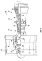
- FIG. 1 schematically illustrates a gas turbine engine 20.
- the gas turbine engine 20 is disclosed herein as a two-spool turbofan that generally incorporates a fan section 22, a compressor section 24, a combustor section 26 and a turbine section 28.
- Alternative engines might include an augmentor section (not shown) among other systems or features.
- the fan section 22 drives air along a bypass flow path B in a bypass duct, while the compressor section 24 drives air along a core flow path C for compression and communication into the combustor section 26 then expansion through the turbine section 28.
- the exemplary engine 20 generally includes a low speed spool 30 and a high speed spool 32 mounted for rotation about an engine central longitudinal axis A relative to an engine static structure 36 via several bearing systems 38. It should be understood that various bearing systems 38 at various locations may alternatively or additionally be provided, and the location of bearing systems 38 may be varied as appropriate to the application.
- the low speed spool 30 generally includes an inner shaft 40 that interconnects a fan 42, a low pressure compressor 44 and a low pressure turbine 46.
- the inner shaft 40 is connected to the fan 42 through a speed change mechanism, which in exemplary gas turbine engine 20 is illustrated as a geared architecture 48 to drive the fan 42 at a lower speed than the low speed spool 30.
- the high speed spool 32 includes an outer shaft 50 that interconnects a high pressure compressor 52 and high pressure turbine 54.
- a combustor 56 is arranged in exemplary gas turbine 20 between the high pressure compressor 52 and the high pressure turbine 54.
- An engine static structure 36 is arranged generally between the high pressure turbine 54 and the low pressure turbine 46.
- the engine static structure 36 further supports bearing systems 38 in the turbine section 28.
- the inner shaft 40 and the outer shaft 50 are concentric and rotate via bearing systems 38 about the engine central longitudinal axis A which is collinear with their longitudinal axes.
- each of the positions of the fan section 22, compressor section 24, combustor section 26, turbine section 28, and fan drive gear system 48 may be varied.
- gear system 48 may be located aft of combustor section 26 or even aft of turbine section 28, and fan section 22 may be positioned forward or aft of the location of gear system 48.
- the engine 20 in one example is a high-bypass geared aircraft engine.
- the engine 20 bypass ratio is greater than about six (6), with an example embodiment being greater than about ten (10)
- the geared architecture 48 is an epicyclic gear train, such as a planetary gear system or other gear system, with a gear reduction ratio of greater than about 2.3
- the low pressure turbine 46 has a pressure ratio that is greater than about five.
- the engine 20 bypass ratio is greater than about ten (10:1)
- the fan diameter is significantly larger than that of the low pressure compressor 44
- the low pressure turbine 46 has a pressure ratio that is greater than about five 5:1.
- Low pressure turbine 46 pressure ratio is pressure measured prior to inlet of low pressure turbine 46 as related to the pressure at the outlet of the low pressure turbine 46 prior to an exhaust nozzle.
- the geared architecture 48 may be an epicycle gear train, such as a planetary gear system or other gear system, with a gear reduction ratio of greater than about 2.3:1. It should be understood, however, that the above parameters are only exemplary of one embodiment of a geared architecture engine and that the present disclosure is applicable to other gas turbine engines including direct drive turbofans.
- the fan section 22 of the engine 20 is designed for a particular flight condition--typically cruise at about 0.8Mach and about 35,000 feet (10,688 meters).
- 'TSFC' Thrust Specific Fuel Consumption
- Low fan pressure ratio is the pressure ratio across the fan blade alone, without a Fan Exit Guide Vane (“FEGV”) system.
- the low fan pressure ratio as disclosed herein according to one non-limiting embodiment is less than about 1.45.
- Low corrected fan tip speed is the actual fan tip speed in ft/sec divided by an industry standard temperature correction of [(Tram °R)/(518.7 °R)] 0.5 .
- the "Low corrected fan tip speed” as disclosed herein according to one non-limiting embodiment is less than about 1150 ft/second (350.5 m/sec).
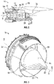
- the gas turbine engine 10 includes an exhaust plug 58 and an exhaust nozzle 60 defining a pathway for the exhaust of combusted core airflow, or core thrust 62. Further, the gas turbine engine 10 includes an inlet 64 and a fan cowl 66 to enclose the fan section 22.
- a fan thrust reverser 68 is included at the gas turbine engine 10 to divert fan airflow 70 radially outwardly and forward during a landing event of an aircraft on which the gas turbine engine 10 is utilized to slow and or stop forward motion of the aircraft. This is achieved by moving a translating sleeve 72 of the fan thrust reverser 68 rearward, which exposes cascade vanes 74, as shown in an upper portion of FIG.
- FIG. 2 While a lower portion of FIG. 2 illustrates the translating sleeve 72 in a stowed position.
- blocker door assemblies 76 are extend across fan flowpath B, thus diverting the fan airflow 70 outwardly and in an upstream direction through the cascade vanes 74.
- the diverted fan airflow 70 must overcome not only the forward momentum of the aircraft, but also the core thrust 62.
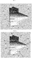
- an exhaust section 78 of the gas turbine engine 20 including the exhaust plug 58 located at the engine central longitudinal axis A, and an exhaust nozzle 60.
- the exhaust nozzle 60 surrounds the exhaust plug 58 and is offset from the exhaust plug 58 in a radial direction to define an exhaust pathway 80 between the exhaust plug 58 and the exhaust nozzle 60 through which core thrust 62 is flowed before exiting to the atmosphere.
- a cross-sectional area of the exhaust pathway 80 is increased. This increases an expansion ratio across the turbine section 28, thus resulting in a lower a discharge velocity and thus core thrust 62 relative to the fan airflow 70.
- the exhaust plug 58 has an axially-extending portion 82, which in some embodiments is substantially cylindrical, and an end portion 84 extending from the axially-extending portion 82.
- the end portion 84 tapers to a plug tip 86 defining a downstream end of the exhaust plug 58.
- the end portion 84 is conical in shape.
- the exhaust plug 58 is movable along the engine central longitudinal axis A relative to the exhaust nozzle 60, between a first position shown in FIG. 4 and a second position, shown in FIG. 5 . Moving the exhaust plug 58 from the first position to the second position increases a cross-sectional area of the exhaust pathway 80. The increase of the cross-sectional area of the exhaust pathway 80 increases the expansion ratio across the turbine section 28, thus resulting in a lower amount of core thrust 62 relative to the fan airflow 70.
- the exhaust plug 58 is connected to a fixed portion 88, over which the exhaust plug 58 moves between the first position and the second position.
- the movement of the exhaust plug 58 may be driven by one or more actuators 90 connecting the fixed portion 88 to the exhaust plug 58.
- the one or more actuators 90 are pneumatically or electrically driven actuators, to withstand the high temperatures of the exhaust section 78 of the gas turbine engine 10.
- the movement of the exhaust plug 58 from the first position to the second position increases the cross-sectional area of the exhaust pathway 80 by up to 20%, in some embodiments in the range of 10% to 20%.
- a 20% area increase may reduce reverse thrust requirements by a corresponding 20% relative to operation of the thrust reverser 68 with the exhaust plug 58 at the first position.
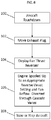
- FIG. 6 illustrates a method of a landing sequence for an aircraft.
- the exhaust plug 58 is moved from the first position to the second position at block 102, thus increasing the cross-sectional area of the exhaust pathway 80.
- the translating sleeve 72 of the fan thrust reverser 68 is translated, thus extending the blocker door assemblies 76 across the fan flowpath B, so that when the gas turbine engine 10 is spooled up to an appropriate reverse thrust setting, the fan airflow 70 is diverted through the cascade vanes 74 at block 106, to slow or stop the aircraft at block 108.
- the steps represented at block 102 and at block 104 may be interchanged in sequencing or happen simultaneously.
Landscapes
- Engineering & Computer Science (AREA)
- Chemical & Material Sciences (AREA)
- Combustion & Propulsion (AREA)
- Mechanical Engineering (AREA)
- General Engineering & Computer Science (AREA)
- Retarders (AREA)
- Control Of Turbines (AREA)
Applications Claiming Priority (1)
| Application Number | Priority Date | Filing Date | Title |
|---|---|---|---|
| US15/619,029 US20180355821A1 (en) | 2017-06-09 | 2017-06-09 | Moveable exhaust plug |
Publications (1)
| Publication Number | Publication Date |
|---|---|
| EP3412902A1 true EP3412902A1 (de) | 2018-12-12 |
Family
ID=62599525
Family Applications (1)
| Application Number | Title | Priority Date | Filing Date |
|---|---|---|---|
| EP18177104.9A Withdrawn EP3412902A1 (de) | 2017-06-09 | 2018-06-11 | Gasturbine mit beweglichem abgasendstück |
Country Status (2)
| Country | Link |
|---|---|
| US (1) | US20180355821A1 (de) |
| EP (1) | EP3412902A1 (de) |
Families Citing this family (1)
| Publication number | Priority date | Publication date | Assignee | Title |
|---|---|---|---|---|
| US10570852B2 (en) | 2017-09-21 | 2020-02-25 | United Technologies Corporation | Moveable exhaust plug liner |
Citations (4)
| Publication number | Priority date | Publication date | Assignee | Title |
|---|---|---|---|---|
| GB1116779A (en) * | 1966-11-23 | 1968-06-12 | Rolls Royce | Gas turbine jet propulsion engine |
| US3841091A (en) * | 1973-05-21 | 1974-10-15 | Gen Electric | Multi-mission tandem propulsion system |
| US4527388A (en) * | 1982-07-12 | 1985-07-09 | The Garrett Corporation | Jet propulsion apparatus and methods |
| US4592508A (en) * | 1983-10-27 | 1986-06-03 | The Boeing Company | Translating jet engine nozzle plug |
Family Cites Families (6)
| Publication number | Priority date | Publication date | Assignee | Title |
|---|---|---|---|---|
| US3386247A (en) * | 1966-09-09 | 1968-06-04 | Gen Electric | Powerplant with thrust reverser |
| GB1177560A (en) * | 1967-12-28 | 1970-01-14 | Rolls Royce | Jet Nozzle. |
| US3807639A (en) * | 1973-05-02 | 1974-04-30 | Snecma | Variable-geometry nozzles for jet propulsion engines |
| US4278220A (en) * | 1979-03-30 | 1981-07-14 | The United States Of America As Represented By The Administrator Of The National Aeronautics And Space Administration | Thrust reverser for a long duct fan engine |
| US4909346A (en) * | 1989-06-27 | 1990-03-20 | Nordam | Jet engine noise suppression system |
| US7886518B2 (en) * | 2006-11-14 | 2011-02-15 | General Electric Company | Turbofan engine cowl assembly and method of operating the same |
-
2017
- 2017-06-09 US US15/619,029 patent/US20180355821A1/en not_active Abandoned
-
2018
- 2018-06-11 EP EP18177104.9A patent/EP3412902A1/de not_active Withdrawn
Patent Citations (4)
| Publication number | Priority date | Publication date | Assignee | Title |
|---|---|---|---|---|
| GB1116779A (en) * | 1966-11-23 | 1968-06-12 | Rolls Royce | Gas turbine jet propulsion engine |
| US3841091A (en) * | 1973-05-21 | 1974-10-15 | Gen Electric | Multi-mission tandem propulsion system |
| US4527388A (en) * | 1982-07-12 | 1985-07-09 | The Garrett Corporation | Jet propulsion apparatus and methods |
| US4592508A (en) * | 1983-10-27 | 1986-06-03 | The Boeing Company | Translating jet engine nozzle plug |
Also Published As
| Publication number | Publication date |
|---|---|
| US20180355821A1 (en) | 2018-12-13 |
Similar Documents
| Publication | Publication Date | Title |
|---|---|---|
| US11092030B2 (en) | Adaptive case for a gas turbine engine | |
| EP3462008B1 (de) | Umschaltbares zapfventil für einen gasturbinenmotor | |
| US10400621B2 (en) | Pivot door thrust reverser with variable area nozzle | |
| EP2957754B1 (de) | Düse mit variablem querschnitt für gasturbinenmotor | |
| US20150275766A1 (en) | Geared turbine engine with a d-duct and a thrust reverser | |
| EP2998522B1 (de) | Verstellbare leitschaufel für einen gasturbinenmotor | |
| EP3869024B1 (de) | Motornebenkanaldüse mit hohem bypass-verhältnis und kontrollierter düsenfläche | |
| US20200088063A1 (en) | Set screw gap control between fixed and variable vanes | |
| EP3450723A1 (de) | Passiv angesteuerte zapfluftumschaltung | |
| EP3412902A1 (de) | Gasturbine mit beweglichem abgasendstück | |
| EP3052769B1 (de) | Übersetzungsverdichter und turbinenrotoren zur abstandssteuerung | |
| EP3470656B1 (de) | Modulierter brennkammer-bypass | |
| EP3460226B1 (de) | Bewegliche abgass-zentralkörper auskleidung | |
| EP3611358B1 (de) | Entlüftungsventilbetätigungssystem | |
| EP3276151B1 (de) | An einem bläsergehäuse montierte schubumkehrerstruktur | |
| EP3508790B1 (de) | Gasturbinenmotor mit einem modulierten brennkammer-bypass und einem brennkammer-bypassventil | |
| US20200141264A1 (en) | Gas turbine engine structure with integrated actuation features | |
| EP3907389B1 (de) | Radialabblasventil für gasturbinenkompressor |
Legal Events
| Date | Code | Title | Description |
|---|---|---|---|
| PUAI | Public reference made under article 153(3) epc to a published international application that has entered the european phase |
Free format text: ORIGINAL CODE: 0009012 |
|
| STAA | Information on the status of an ep patent application or granted ep patent |
Free format text: STATUS: THE APPLICATION HAS BEEN PUBLISHED |
|
| AK | Designated contracting states |
Kind code of ref document: A1 Designated state(s): AL AT BE BG CH CY CZ DE DK EE ES FI FR GB GR HR HU IE IS IT LI LT LU LV MC MK MT NL NO PL PT RO RS SE SI SK SM TR |
|
| AX | Request for extension of the european patent |
Extension state: BA ME |
|
| STAA | Information on the status of an ep patent application or granted ep patent |
Free format text: STATUS: REQUEST FOR EXAMINATION WAS MADE |
|
| 17P | Request for examination filed |
Effective date: 20190612 |
|
| RBV | Designated contracting states (corrected) |
Designated state(s): AL AT BE BG CH CY CZ DE DK EE ES FI FR GB GR HR HU IE IS IT LI LT LU LV MC MK MT NL NO PL PT RO RS SE SI SK SM TR |
|
| STAA | Information on the status of an ep patent application or granted ep patent |
Free format text: STATUS: EXAMINATION IS IN PROGRESS |
|
| 17Q | First examination report despatched |
Effective date: 20200909 |
|
| RAP1 | Party data changed (applicant data changed or rights of an application transferred) |
Owner name: RAYTHEON TECHNOLOGIES CORPORATION |
|
| STAA | Information on the status of an ep patent application or granted ep patent |
Free format text: STATUS: THE APPLICATION IS DEEMED TO BE WITHDRAWN |
|
| 18D | Application deemed to be withdrawn |
Effective date: 20220104 |