EP3907389B1 - Radialabblasventil für gasturbinenkompressor - Google Patents
Radialabblasventil für gasturbinenkompressor Download PDFInfo
- Publication number
- EP3907389B1 EP3907389B1 EP21172406.7A EP21172406A EP3907389B1 EP 3907389 B1 EP3907389 B1 EP 3907389B1 EP 21172406 A EP21172406 A EP 21172406A EP 3907389 B1 EP3907389 B1 EP 3907389B1
- Authority
- EP
- European Patent Office
- Prior art keywords
- bleed
- door
- doors
- duct
- circumferential end
- Prior art date
- Legal status (The legal status is an assumption and is not a legal conclusion. Google has not performed a legal analysis and makes no representation as to the accuracy of the status listed.)
- Active
Links
Images


Classifications
-
- F—MECHANICAL ENGINEERING; LIGHTING; HEATING; WEAPONS; BLASTING
- F02—COMBUSTION ENGINES; HOT-GAS OR COMBUSTION-PRODUCT ENGINE PLANTS
- F02C—GAS-TURBINE PLANTS; AIR INTAKES FOR JET-PROPULSION PLANTS; CONTROLLING FUEL SUPPLY IN AIR-BREATHING JET-PROPULSION PLANTS
- F02C6/00—Plural gas-turbine plants; Combinations of gas-turbine plants with other apparatus; Adaptations of gas-turbine plants for special use
- F02C6/04—Gas-turbine plants providing heated or pressurised working fluid for other apparatus, e.g. without mechanical power output
- F02C6/06—Gas-turbine plants providing heated or pressurised working fluid for other apparatus, e.g. without mechanical power output providing compressed gas
- F02C6/08—Gas-turbine plants providing heated or pressurised working fluid for other apparatus, e.g. without mechanical power output providing compressed gas the gas being bled from the gas-turbine compressor
-
- F—MECHANICAL ENGINEERING; LIGHTING; HEATING; WEAPONS; BLASTING
- F04—POSITIVE - DISPLACEMENT MACHINES FOR LIQUIDS; PUMPS FOR LIQUIDS OR ELASTIC FLUIDS
- F04D—NON-POSITIVE-DISPLACEMENT PUMPS
- F04D27/00—Control, e.g. regulation, of pumps, pumping installations or pumping systems specially adapted for elastic fluids
- F04D27/02—Surge control
- F04D27/0207—Surge control by bleeding, bypassing or recycling fluids
- F04D27/0215—Arrangements therefor, e.g. bleed or by-pass valves
-
- F—MECHANICAL ENGINEERING; LIGHTING; HEATING; WEAPONS; BLASTING
- F04—POSITIVE - DISPLACEMENT MACHINES FOR LIQUIDS; PUMPS FOR LIQUIDS OR ELASTIC FLUIDS
- F04D—NON-POSITIVE-DISPLACEMENT PUMPS
- F04D27/00—Control, e.g. regulation, of pumps, pumping installations or pumping systems specially adapted for elastic fluids
- F04D27/02—Surge control
- F04D27/0207—Surge control by bleeding, bypassing or recycling fluids
- F04D27/023—Details or means for fluid extraction
-
- F—MECHANICAL ENGINEERING; LIGHTING; HEATING; WEAPONS; BLASTING
- F02—COMBUSTION ENGINES; HOT-GAS OR COMBUSTION-PRODUCT ENGINE PLANTS
- F02K—JET-PROPULSION PLANTS
- F02K3/00—Plants including a gas turbine driving a compressor or a ducted fan
- F02K3/02—Plants including a gas turbine driving a compressor or a ducted fan in which part of the working fluid by-passes the turbine and combustion chamber
- F02K3/04—Plants including a gas turbine driving a compressor or a ducted fan in which part of the working fluid by-passes the turbine and combustion chamber the plant including ducted fans, i.e. fans with high volume, low pressure outputs, for augmenting the jet thrust, e.g. of double-flow type
- F02K3/075—Plants including a gas turbine driving a compressor or a ducted fan in which part of the working fluid by-passes the turbine and combustion chamber the plant including ducted fans, i.e. fans with high volume, low pressure outputs, for augmenting the jet thrust, e.g. of double-flow type controlling flow ratio between flows
-
- F—MECHANICAL ENGINEERING; LIGHTING; HEATING; WEAPONS; BLASTING
- F05—INDEXING SCHEMES RELATING TO ENGINES OR PUMPS IN VARIOUS SUBCLASSES OF CLASSES F01-F04
- F05D—INDEXING SCHEME FOR ASPECTS RELATING TO NON-POSITIVE-DISPLACEMENT MACHINES OR ENGINES, GAS-TURBINES OR JET-PROPULSION PLANTS
- F05D2220/00—Application
- F05D2220/30—Application in turbines
- F05D2220/32—Application in turbines in gas turbines
- F05D2220/323—Application in turbines in gas turbines for aircraft propulsion, e.g. jet engines
-
- F—MECHANICAL ENGINEERING; LIGHTING; HEATING; WEAPONS; BLASTING
- F05—INDEXING SCHEMES RELATING TO ENGINES OR PUMPS IN VARIOUS SUBCLASSES OF CLASSES F01-F04
- F05D—INDEXING SCHEME FOR ASPECTS RELATING TO NON-POSITIVE-DISPLACEMENT MACHINES OR ENGINES, GAS-TURBINES OR JET-PROPULSION PLANTS
- F05D2240/00—Components
- F05D2240/35—Combustors or associated equipment
-
- F—MECHANICAL ENGINEERING; LIGHTING; HEATING; WEAPONS; BLASTING
- F05—INDEXING SCHEMES RELATING TO ENGINES OR PUMPS IN VARIOUS SUBCLASSES OF CLASSES F01-F04
- F05D—INDEXING SCHEME FOR ASPECTS RELATING TO NON-POSITIVE-DISPLACEMENT MACHINES OR ENGINES, GAS-TURBINES OR JET-PROPULSION PLANTS
- F05D2240/00—Components
- F05D2240/55—Seals
-
- F—MECHANICAL ENGINEERING; LIGHTING; HEATING; WEAPONS; BLASTING
- F05—INDEXING SCHEMES RELATING TO ENGINES OR PUMPS IN VARIOUS SUBCLASSES OF CLASSES F01-F04
- F05D—INDEXING SCHEME FOR ASPECTS RELATING TO NON-POSITIVE-DISPLACEMENT MACHINES OR ENGINES, GAS-TURBINES OR JET-PROPULSION PLANTS
- F05D2250/00—Geometry
- F05D2250/40—Movement of components
- F05D2250/41—Movement of components with one degree of freedom
- F05D2250/411—Movement of components with one degree of freedom in rotation
-
- F—MECHANICAL ENGINEERING; LIGHTING; HEATING; WEAPONS; BLASTING
- F05—INDEXING SCHEMES RELATING TO ENGINES OR PUMPS IN VARIOUS SUBCLASSES OF CLASSES F01-F04
- F05D—INDEXING SCHEME FOR ASPECTS RELATING TO NON-POSITIVE-DISPLACEMENT MACHINES OR ENGINES, GAS-TURBINES OR JET-PROPULSION PLANTS
- F05D2260/00—Function
- F05D2260/50—Kinematic linkage, i.e. transmission of position
-
- F—MECHANICAL ENGINEERING; LIGHTING; HEATING; WEAPONS; BLASTING
- F05—INDEXING SCHEMES RELATING TO ENGINES OR PUMPS IN VARIOUS SUBCLASSES OF CLASSES F01-F04
- F05D—INDEXING SCHEME FOR ASPECTS RELATING TO NON-POSITIVE-DISPLACEMENT MACHINES OR ENGINES, GAS-TURBINES OR JET-PROPULSION PLANTS
- F05D2270/00—Control
- F05D2270/01—Purpose of the control system
- F05D2270/10—Purpose of the control system to cope with, or avoid, compressor flow instabilities
- F05D2270/101—Compressor surge or stall
Definitions
- Exemplary embodiments of the present invention pertain to the art of gas turbine engines, and in particular to bleed valve configurations of compressors of gas turbine engines.
- a gas turbine engine typically includes one or more bleed valves to bleed airflow from the compressor section.
- bleed valves may bleed airflow from the compressor section at a high pressure compressor or at a low pressure compressor of the gas turbine engine.
- the bleed valves are opened at operating conditions such as engine start to remove excess airflow from the core flowpath, and also opened during operation for, for example, engine surge avoidance.
- a bleed valve is a low pressure compressor exit bleed valve, which when open allows airflow to bleed from the low compressor section.
- the bleed valve is an annular ring covering a bleed duct, the bleed duct extending from the compressor flow path.
- the annular ring is moved axially and circumferentially. This axial motion of the valve requires additional axial space around the valve location to accommodate the axial travel of the valve.
- placement of flanges and/or other features of the compressor may be limited by the need for this additional axial space.
- US 5,048,286 discloses a bypass valve system wherein valve doors move in an axial and radial direction when actuated by circumferential travel of an actuation ring.
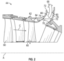
- a bleed system for a gas turbine engine includes a bleed duct having a duct inlet for locating at a flowpath of a gas turbine engine, and a duct outlet for locating outside of the flowpath, the bleed duct extending circumferentially around a central longitudinal axis.
- a plurality of bleed doors are located at the duct reed outlet and are arrayed along a circumferential length on the bleed duct.
- Each bleed door includes a first circumferential end, and a second circumferential end.
- the plurality of bleed doors are arrayed such that when the plurality of bleed doors are in a closed position the first circumferential end is located at the second circumferential end of an adjacent bleed door of the plurality of bleed doors.
- Each bleed door includes a pivot, such that each bleed door rotates about the pivot from the closed position covering the duct outlet to an opened position for allowing a bleed airflow to pass through the duct outlet.
- the bleed doors When the plurality of bleed doors are in the opened position, the bleed doors extend from their pivots in a circumferential swirl direction of the bleed airflow through the bleed duct.
- the bleed system includes a synchronization ring, and a linkage arm extending from the synchronization ring to a bleed door of the plurality of bleed doors such that circumferential movement of the synchronization ring about the central longitudinal axis urges rotation of the bleed door about the pivot between the closed position and the open position.
- the linkage arm is connected to the bleed door between the pivot and the first circumferential end of the bleed door.
- the pivot is located at or near the second circumferential end of the bleed door.
- each bleed door of the plurality of bleed doors circumferentially overlaps the second circumferential end of the adjacent bleed door of the plurality of bleed doors.
- each bleed door of the plurality of bleed doors includes a perimetrical seal to seal the bleed door to the duct outlet when the bleed door is in the closed position.
- each bleed door of the plurality of bleed doors includes an inner radial surface extending through the duct outlet into the bleed duct when the bleed door is in the closed position.
- the inner radial surface is profiled to allow for smooth egress of the bleed airflow from the duct outlet.
- a gas turbine engine includes a combustor, a turbine driven by combustion gases output from the combustor, and a compressor driven by the turbine, the compressor including the bleed system described above.
- the pivot is secured to a fixed structure of the gas turbine engine.
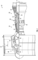
- FIG. 1 schematically illustrates a gas turbine engine 20.
- the gas turbine engine 20 is disclosed herein as a two-spool turbofan that generally incorporates a fan section 22, a compressor section 24, a combustor section 26 and a turbine section 28.
- Alternative engines might include other systems or features.
- the fan section 22 drives air along a bypass flow path B in a bypass duct, while the compressor section 24 drives air along a core flow path C for compression and communication into the combustor section 26 then expansion through the turbine section 28.
- FIG. 1 schematically illustrates a gas turbine engine 20.
- the gas turbine engine 20 is disclosed herein as a two-spool turbofan that generally incorporates a fan section 22, a compressor section 24, a combustor section 26 and a turbine section 28.
- Alternative engines might include other systems or features.
- the fan section 22 drives air along a bypass flow path B in a bypass duct
- the compressor section 24 drives air along a core flow path C for compression and communication into the combustor section 26
- the exemplary engine 20 generally includes a low speed spool 30 and a high speed spool 32 mounted for rotation about an engine central longitudinal axis A relative to an engine static structure 36 via several bearing systems 38. It should be understood that various bearing systems 38 at various locations may alternatively or additionally be provided, and the location of bearing systems 38 may be varied as appropriate to the application.
- the low speed spool 30 generally includes an inner shaft 40 that interconnects a fan 42, a low pressure compressor 44 and a low pressure turbine 46.
- the inner shaft 40 is connected to the fan 42 through a speed change mechanism, which in exemplary gas turbine engine 20 is illustrated as a geared architecture 48 to drive the fan 42 at a lower speed than the low speed spool 30.
- the high speed spool 32 includes an outer shaft 50 that interconnects a high pressure compressor 52 and high pressure turbine 54.
- a combustor 56 is arranged in exemplary gas turbine 20 between the high pressure compressor 52 and the high pressure turbine 54.
- An engine static structure 36 is arranged generally between the high pressure turbine 54 and the low pressure turbine 46.
- the engine static structure 36 further supports bearing systems 38 in the turbine section 28.
- the inner shaft 40 and the outer shaft 50 are concentric and rotate via bearing systems 38 about the engine central longitudinal axis A which is collinear with their longitudinal axes.
- each of the positions of the fan section 22, compressor section 24, combustor section 26, turbine section 28, and fan drive gear system 48 may be varied.
- gear system 48 may be located aft of combustor section 26 or even aft of turbine section 28, and fan section 22 may be positioned forward or aft of the location of gear system 48.
- the engine 20 in one example is a high-bypass geared aircraft engine.
- the engine 20 bypass ratio is greater than about six (6), with an example embodiment being greater than about ten (10)
- the geared architecture 48 is an epicyclic gear train, such as a planetary gear system or other gear system, with a gear reduction ratio of greater than about 2.3
- the low pressure turbine 46 has a pressure ratio that is greater than about five.
- the engine 20 bypass ratio is greater than about ten (10:1)
- the fan diameter is significantly larger than that of the low pressure compressor 44
- the low pressure turbine 46 has a pressure ratio that is greater than about five 5: 1.
- the fan section 22 of the engine 20 is designed for a particular flight condition--typically cruise at about 0.8Mach and about 35,000 feet (10,688 meters).
- 'TSFC' Thrust Specific Fuel Consumption
- Low fan pressure ratio is the pressure ratio across the fan blade alone, without a Fan Exit Guide Vane (“FEGV”) system.
Landscapes
- Engineering & Computer Science (AREA)
- Mechanical Engineering (AREA)
- General Engineering & Computer Science (AREA)
- Life Sciences & Earth Sciences (AREA)
- Sustainable Development (AREA)
- Chemical & Material Sciences (AREA)
- Combustion & Propulsion (AREA)
- Structures Of Non-Positive Displacement Pumps (AREA)
Claims (10)
- Abblassystem für ein Gasturbinentriebwerk (20), umfassend:einen Abblaskanal (66), der einen Kanaleinlass (70) zum Anordnen an einem Strömungsweg eines Gasturbinentriebwerks und einem Kanalauslass (72) zum Anordnen außerhalb des Strömungswegs aufweist, wobei sich der Abblaskanal kreisförmig um eine zentrale Längsachse erstreckt;eine Vielzahl von Abblasklappen (86), die an dem Kanalauslass angeordnet ist und entlang einer Umfangslänge auf dem Abblaskanal gruppiert ist, wobei jede Abblasklappe Folgendes beinhaltet:ein erstes Umfangsende (92);ein zweites Umfangsende (94), wobei die Vielzahl von Abblasklappen derart gruppiert ist, dass das erste Umfangsende an dem zweiten Umfangsende einer benachbarten Abblasklappe der Vielzahl von Abblasklappen angeordnet ist, wenn sich die Vielzahl von Abblasklappen in einer geschlossenen Position befindet; undeinen Drehzapfen (104) derart, dass sich jede Abblasklappe aus der geschlossenen Position, in der sie den Kanalauslass (72) abdeckt, um den Drehzapfen in eine geöffnete Position dreht, um ein Passieren eines Abblasluftstroms (68) durch den Kanalauslass zu ermöglichen;dadurch gekennzeichnet, dass sich die Abblasklappen (86) von ihrem Drehzapfen (104) in einer Umfangswirbelrichtung des Abblasluftstroms (68) durch den Abblaskanal (66) erstrecken, wenn sich die Vielzahl von Abblasklappen in der geöffneten Position befindet.
- Abblasystem nach Anspruch 1, ferner umfassend:einen Synchronisierring (100); undeinen Verbindungsarm (102), der sich derart von dem Synchronisierring zu einer Abblasklappe (86) der Vielzahl von Abblasklappen erstreckt, dass eine Umfangsbewegung des Synchronisierrings um die zentrale Längsachse eine Drehung der Abblasklappe um den Drehzapfen (104) zwischen der geschlossenen Position und der offenen Position erzwingt.
- Abblassystem nach Anspruch 2, wobei der Verbindungsarm (102) zwischen dem Drehzapfen (104) und dem ersten Umfangsende (92) der Abblasklappe mit der Abblasklappe (86) verbunden ist.
- Abblassystem nach einem der vorhergehenden Ansprüche, wobei der Drehzapfen (104) an oder nahe dem zweiten Umfangsende (94) der Abblasklappe (86) angeordnet ist.
- Abblassystem nach einem der vorhergehenden Ansprüche, wobei das erste Umfangsende (92) jeder Abblasklappe (86) der Vielzahl von Abblasklappen das zweite Umfangsende (94) der benachbarten Abblasklappe der Vielzahl von Abblasklappen in Umfangsrichtung überlappt.
- Abblassystem nach einem der vorhergehenden Ansprüche, wobei jede Abblasklappe (86) der Vielzahl von Abblasklappen eine Perimeterdichtung beinhaltet, um die Abblasklappe gegenüber dem Kanalauslass (72) abzudichten, wenn sich die Abblasklappe in der geschlossenen Position befindet.
- Abblassystem nach einem der vorhergehenden Ansprüche, wobei jede Abblasklappe (86) der Vielzahl von Abblasklappen eine innere radiale Fläche (88) beinhaltet, die sich durch den Kanalauslass (72) in den Abblaskanal (66) erstreckt, wenn sich die Abblasklappe in der geschlossenen Position befindet.
- Abblassystem nach Anspruch 7, wobei die innere radiale Fläche (88) profiliert ist, um einen gleichmäßigen Austritt des Abblasluftstroms (68) aus dem Kanalauslass (72) zu ermöglichen.
- Gasturbinentriebwerk (20), umfassend:eine Brennkammer (56);eine Turbine (46, 54), die von Verbrennungsgasen angetrieben wird, die aus der Brennkammer abgegeben werden; undeinen von der Turbine angetriebenen Kompressor (44, 52), wobei der Kompressor das Abblassystem nach einem der vorhergehenden Ansprüche umfasst.
- Gasturbinentriebwerk (20) nach Anspruch 9, wobei der Drehzapfen (104) an einer festen Konstruktion des Gasturbinentriebwerks (20) befestigt ist.
Applications Claiming Priority (1)
| Application Number | Priority Date | Filing Date | Title |
|---|---|---|---|
| US16/869,847 US11428234B2 (en) | 2020-05-08 | 2020-05-08 | Gas turbine compressor radial door bleed valve |
Publications (2)
| Publication Number | Publication Date |
|---|---|
| EP3907389A1 EP3907389A1 (de) | 2021-11-10 |
| EP3907389B1 true EP3907389B1 (de) | 2025-06-25 |
Family
ID=75825623
Family Applications (1)
| Application Number | Title | Priority Date | Filing Date |
|---|---|---|---|
| EP21172406.7A Active EP3907389B1 (de) | 2020-05-08 | 2021-05-06 | Radialabblasventil für gasturbinenkompressor |
Country Status (2)
| Country | Link |
|---|---|
| US (1) | US11428234B2 (de) |
| EP (1) | EP3907389B1 (de) |
Family Cites Families (8)
| Publication number | Priority date | Publication date | Assignee | Title |
|---|---|---|---|---|
| DE1114980B (de) * | 1959-10-02 | 1961-10-12 | Entwicklungsbau Pirna Veb | Luftabblaseeinrichtung an Axialverdichtern von Gasturbinen |
| US5048286A (en) * | 1990-06-29 | 1991-09-17 | General Electric Company | Bypass valve door |
| US5054286A (en) | 1990-06-29 | 1991-10-08 | General Electric Company | Bypass valve system |
| US6048171A (en) | 1997-09-09 | 2000-04-11 | United Technologies Corporation | Bleed valve system |
| GB2473578B (en) | 2006-01-20 | 2011-08-03 | Rolls Royce Power Eng | Gas turbine engine system |
| DE102013215371A1 (de) * | 2013-08-05 | 2015-02-05 | Rolls-Royce Deutschland Ltd & Co Kg | Vorrichtung und Verfahren zum Abblasen von Verdichterluft in einem Triebwerk |
| US10287992B2 (en) | 2015-08-26 | 2019-05-14 | General Electric Company | Gas turbine engine hybrid variable bleed valve |
| US10830179B2 (en) | 2017-03-01 | 2020-11-10 | General Electric Company | Variable bleed valve door assembly and system for gas turbine engines |
-
2020
- 2020-05-08 US US16/869,847 patent/US11428234B2/en active Active
-
2021
- 2021-05-06 EP EP21172406.7A patent/EP3907389B1/de active Active
Also Published As
| Publication number | Publication date |
|---|---|
| US20210348618A1 (en) | 2021-11-11 |
| US11428234B2 (en) | 2022-08-30 |
| EP3907389A1 (de) | 2021-11-10 |
Similar Documents
| Publication | Publication Date | Title |
|---|---|---|
| US11092030B2 (en) | Adaptive case for a gas turbine engine | |
| EP3536912B1 (de) | Schaufelbetätigungssystem mit profiliertem winkelhebel | |
| EP3760838B1 (de) | Verstellbares schaufelsystem von gasturbinenmotoren und verfahren | |
| EP3869024B1 (de) | Motornebenkanaldüse mit hohem bypass-verhältnis und kontrollierter düsenfläche | |
| EP3748147B1 (de) | Entlüftungsventil für die dämpfungsführungsverbindung eines gasturbinenmotors | |
| EP3772570A1 (de) | Hydrostatische dichtung mit verlängertem trägerarm | |
| EP3623584B1 (de) | Stellschraubenspaltregelung zwischen festen und variablen schaufeln | |
| EP3907389B1 (de) | Radialabblasventil für gasturbinenkompressor | |
| EP3623587B1 (de) | Schaufelprofilanordnug für ein gasturbinentriebwerk | |
| EP3470656B1 (de) | Modulierter brennkammer-bypass | |
| EP3502455B1 (de) | Entlüftungsventilsystem | |
| EP3611358B1 (de) | Entlüftungsventilbetätigungssystem | |
| US11181004B2 (en) | Confinement of a rope seal about a passage using a backing plate | |
| EP3508790B1 (de) | Gasturbinenmotor mit einem modulierten brennkammer-bypass und einem brennkammer-bypassventil | |
| EP4556684A1 (de) | Schieberdichtung für gasturbinenmotor | |
| EP4372208A1 (de) | Dichtung für gasturbinenmotor | |
| US20200141264A1 (en) | Gas turbine engine structure with integrated actuation features | |
| EP3715641B1 (de) | Gekerbter axialflansch für einen kompressor mit geteiltem gehäuse | |
| EP3460226B1 (de) | Bewegliche abgass-zentralkörper auskleidung | |
| EP3495621B1 (de) | Stützring für ein gasturbinentriebwerk | |
| EP3550113A2 (de) | Gasturbinenmotor mit freitragenden statoren mit dichtungselementen | |
| EP3428404A1 (de) | Leitschaufelanordnung für einen gasturbinenmotor |
Legal Events
| Date | Code | Title | Description |
|---|---|---|---|
| PUAI | Public reference made under article 153(3) epc to a published international application that has entered the european phase |
Free format text: ORIGINAL CODE: 0009012 |
|
| STAA | Information on the status of an ep patent application or granted ep patent |
Free format text: STATUS: THE APPLICATION HAS BEEN PUBLISHED |
|
| AK | Designated contracting states |
Kind code of ref document: A1 Designated state(s): AL AT BE BG CH CY CZ DE DK EE ES FI FR GB GR HR HU IE IS IT LI LT LU LV MC MK MT NL NO PL PT RO RS SE SI SK SM TR |
|
| B565 | Issuance of search results under rule 164(2) epc |
Effective date: 20211008 |
|
| STAA | Information on the status of an ep patent application or granted ep patent |
Free format text: STATUS: REQUEST FOR EXAMINATION WAS MADE |
|
| 17P | Request for examination filed |
Effective date: 20220510 |
|
| RBV | Designated contracting states (corrected) |
Designated state(s): AL AT BE BG CH CY CZ DE DK EE ES FI FR GB GR HR HU IE IS IT LI LT LU LV MC MK MT NL NO PL PT RO RS SE SI SK SM TR |
|
| STAA | Information on the status of an ep patent application or granted ep patent |
Free format text: STATUS: EXAMINATION IS IN PROGRESS |
|
| 17Q | First examination report despatched |
Effective date: 20230613 |
|
| RAP3 | Party data changed (applicant data changed or rights of an application transferred) |
Owner name: RTX CORPORATION |
|
| GRAP | Despatch of communication of intention to grant a patent |
Free format text: ORIGINAL CODE: EPIDOSNIGR1 |
|
| STAA | Information on the status of an ep patent application or granted ep patent |
Free format text: STATUS: GRANT OF PATENT IS INTENDED |
|
| INTG | Intention to grant announced |
Effective date: 20250117 |
|
| GRAS | Grant fee paid |
Free format text: ORIGINAL CODE: EPIDOSNIGR3 |
|
| GRAA | (expected) grant |
Free format text: ORIGINAL CODE: 0009210 |
|
| STAA | Information on the status of an ep patent application or granted ep patent |
Free format text: STATUS: THE PATENT HAS BEEN GRANTED |
|
| AK | Designated contracting states |
Kind code of ref document: B1 Designated state(s): AL AT BE BG CH CY CZ DE DK EE ES FI FR GB GR HR HU IE IS IT LI LT LU LV MC MK MT NL NO PL PT RO RS SE SI SK SM TR |
|
| REG | Reference to a national code |
Ref country code: GB Ref legal event code: FG4D |
|
| REG | Reference to a national code |
Ref country code: CH Ref legal event code: EP |
|
| REG | Reference to a national code |
Ref country code: CH Ref legal event code: EP |
|
| REG | Reference to a national code |
Ref country code: IE Ref legal event code: FG4D |
|
| REG | Reference to a national code |
Ref country code: DE Ref legal event code: R096 Ref document number: 602021032696 Country of ref document: DE |
|
| PG25 | Lapsed in a contracting state [announced via postgrant information from national office to epo] |
Ref country code: FI Free format text: LAPSE BECAUSE OF FAILURE TO SUBMIT A TRANSLATION OF THE DESCRIPTION OR TO PAY THE FEE WITHIN THE PRESCRIBED TIME-LIMIT Effective date: 20250625 |
|
| REG | Reference to a national code |
Ref country code: LT Ref legal event code: MG9D |
|
| PG25 | Lapsed in a contracting state [announced via postgrant information from national office to epo] |
Ref country code: NO Free format text: LAPSE BECAUSE OF FAILURE TO SUBMIT A TRANSLATION OF THE DESCRIPTION OR TO PAY THE FEE WITHIN THE PRESCRIBED TIME-LIMIT Effective date: 20250925 Ref country code: GR Free format text: LAPSE BECAUSE OF FAILURE TO SUBMIT A TRANSLATION OF THE DESCRIPTION OR TO PAY THE FEE WITHIN THE PRESCRIBED TIME-LIMIT Effective date: 20250926 |
|
| PG25 | Lapsed in a contracting state [announced via postgrant information from national office to epo] |
Ref country code: BG Free format text: LAPSE BECAUSE OF FAILURE TO SUBMIT A TRANSLATION OF THE DESCRIPTION OR TO PAY THE FEE WITHIN THE PRESCRIBED TIME-LIMIT Effective date: 20250625 |
|
| PG25 | Lapsed in a contracting state [announced via postgrant information from national office to epo] |
Ref country code: HR Free format text: LAPSE BECAUSE OF FAILURE TO SUBMIT A TRANSLATION OF THE DESCRIPTION OR TO PAY THE FEE WITHIN THE PRESCRIBED TIME-LIMIT Effective date: 20250625 |
|
| PG25 | Lapsed in a contracting state [announced via postgrant information from national office to epo] |
Ref country code: RS Free format text: LAPSE BECAUSE OF FAILURE TO SUBMIT A TRANSLATION OF THE DESCRIPTION OR TO PAY THE FEE WITHIN THE PRESCRIBED TIME-LIMIT Effective date: 20250925 |
|
| PG25 | Lapsed in a contracting state [announced via postgrant information from national office to epo] |
Ref country code: LV Free format text: LAPSE BECAUSE OF FAILURE TO SUBMIT A TRANSLATION OF THE DESCRIPTION OR TO PAY THE FEE WITHIN THE PRESCRIBED TIME-LIMIT Effective date: 20250625 |
|
| REG | Reference to a national code |
Ref country code: NL Ref legal event code: MP Effective date: 20250625 |
|
| PG25 | Lapsed in a contracting state [announced via postgrant information from national office to epo] |
Ref country code: NL Free format text: LAPSE BECAUSE OF FAILURE TO SUBMIT A TRANSLATION OF THE DESCRIPTION OR TO PAY THE FEE WITHIN THE PRESCRIBED TIME-LIMIT Effective date: 20250625 |
|
| PG25 | Lapsed in a contracting state [announced via postgrant information from national office to epo] |
Ref country code: PT Free format text: LAPSE BECAUSE OF FAILURE TO SUBMIT A TRANSLATION OF THE DESCRIPTION OR TO PAY THE FEE WITHIN THE PRESCRIBED TIME-LIMIT Effective date: 20251027 |
|
| REG | Reference to a national code |
Ref country code: AT Ref legal event code: MK05 Ref document number: 1806646 Country of ref document: AT Kind code of ref document: T Effective date: 20250625 |
|
| PG25 | Lapsed in a contracting state [announced via postgrant information from national office to epo] |
Ref country code: IS Free format text: LAPSE BECAUSE OF FAILURE TO SUBMIT A TRANSLATION OF THE DESCRIPTION OR TO PAY THE FEE WITHIN THE PRESCRIBED TIME-LIMIT Effective date: 20251025 |
|
| PG25 | Lapsed in a contracting state [announced via postgrant information from national office to epo] |
Ref country code: AT Free format text: LAPSE BECAUSE OF FAILURE TO SUBMIT A TRANSLATION OF THE DESCRIPTION OR TO PAY THE FEE WITHIN THE PRESCRIBED TIME-LIMIT Effective date: 20250625 Ref country code: SM Free format text: LAPSE BECAUSE OF FAILURE TO SUBMIT A TRANSLATION OF THE DESCRIPTION OR TO PAY THE FEE WITHIN THE PRESCRIBED TIME-LIMIT Effective date: 20250625 |
|
| PG25 | Lapsed in a contracting state [announced via postgrant information from national office to epo] |
Ref country code: CZ Free format text: LAPSE BECAUSE OF FAILURE TO SUBMIT A TRANSLATION OF THE DESCRIPTION OR TO PAY THE FEE WITHIN THE PRESCRIBED TIME-LIMIT Effective date: 20250625 |
|
| PG25 | Lapsed in a contracting state [announced via postgrant information from national office to epo] |
Ref country code: PL Free format text: LAPSE BECAUSE OF FAILURE TO SUBMIT A TRANSLATION OF THE DESCRIPTION OR TO PAY THE FEE WITHIN THE PRESCRIBED TIME-LIMIT Effective date: 20250625 |
|
| PG25 | Lapsed in a contracting state [announced via postgrant information from national office to epo] |
Ref country code: EE Free format text: LAPSE BECAUSE OF FAILURE TO SUBMIT A TRANSLATION OF THE DESCRIPTION OR TO PAY THE FEE WITHIN THE PRESCRIBED TIME-LIMIT Effective date: 20250625 |
|
| PG25 | Lapsed in a contracting state [announced via postgrant information from national office to epo] |
Ref country code: SK Free format text: LAPSE BECAUSE OF FAILURE TO SUBMIT A TRANSLATION OF THE DESCRIPTION OR TO PAY THE FEE WITHIN THE PRESCRIBED TIME-LIMIT Effective date: 20250625 |
|
| PG25 | Lapsed in a contracting state [announced via postgrant information from national office to epo] |
Ref country code: ES Free format text: LAPSE BECAUSE OF FAILURE TO SUBMIT A TRANSLATION OF THE DESCRIPTION OR TO PAY THE FEE WITHIN THE PRESCRIBED TIME-LIMIT Effective date: 20250625 |
|
| PG25 | Lapsed in a contracting state [announced via postgrant information from national office to epo] |
Ref country code: DK Free format text: LAPSE BECAUSE OF FAILURE TO SUBMIT A TRANSLATION OF THE DESCRIPTION OR TO PAY THE FEE WITHIN THE PRESCRIBED TIME-LIMIT Effective date: 20250625 |
|
| PG25 | Lapsed in a contracting state [announced via postgrant information from national office to epo] |
Ref country code: IT Free format text: LAPSE BECAUSE OF FAILURE TO SUBMIT A TRANSLATION OF THE DESCRIPTION OR TO PAY THE FEE WITHIN THE PRESCRIBED TIME-LIMIT Effective date: 20250625 |