EP3412492A1 - Charging device and positional deviation detection method - Google Patents
Charging device and positional deviation detection method Download PDFInfo
- Publication number
- EP3412492A1 EP3412492A1 EP16889434.3A EP16889434A EP3412492A1 EP 3412492 A1 EP3412492 A1 EP 3412492A1 EP 16889434 A EP16889434 A EP 16889434A EP 3412492 A1 EP3412492 A1 EP 3412492A1
- Authority
- EP
- European Patent Office
- Prior art keywords
- plane
- bus
- point
- positional deviation
- vertical distance
- Prior art date
- Legal status (The legal status is an assumption and is not a legal conclusion. Google has not performed a legal analysis and makes no representation as to the accuracy of the status listed.)
- Withdrawn
Links
Images








Classifications
-
- B—PERFORMING OPERATIONS; TRANSPORTING
- B60—VEHICLES IN GENERAL
- B60L—PROPULSION OF ELECTRICALLY-PROPELLED VEHICLES; SUPPLYING ELECTRIC POWER FOR AUXILIARY EQUIPMENT OF ELECTRICALLY-PROPELLED VEHICLES; ELECTRODYNAMIC BRAKE SYSTEMS FOR VEHICLES IN GENERAL; MAGNETIC SUSPENSION OR LEVITATION FOR VEHICLES; MONITORING OPERATING VARIABLES OF ELECTRICALLY-PROPELLED VEHICLES; ELECTRIC SAFETY DEVICES FOR ELECTRICALLY-PROPELLED VEHICLES
- B60L50/00—Electric propulsion with power supplied within the vehicle
- B60L50/50—Electric propulsion with power supplied within the vehicle using propulsion power supplied by batteries or fuel cells
- B60L50/60—Electric propulsion with power supplied within the vehicle using propulsion power supplied by batteries or fuel cells using power supplied by batteries
-
- B—PERFORMING OPERATIONS; TRANSPORTING
- B60—VEHICLES IN GENERAL
- B60L—PROPULSION OF ELECTRICALLY-PROPELLED VEHICLES; SUPPLYING ELECTRIC POWER FOR AUXILIARY EQUIPMENT OF ELECTRICALLY-PROPELLED VEHICLES; ELECTRODYNAMIC BRAKE SYSTEMS FOR VEHICLES IN GENERAL; MAGNETIC SUSPENSION OR LEVITATION FOR VEHICLES; MONITORING OPERATING VARIABLES OF ELECTRICALLY-PROPELLED VEHICLES; ELECTRIC SAFETY DEVICES FOR ELECTRICALLY-PROPELLED VEHICLES
- B60L53/00—Methods of charging batteries, specially adapted for electric vehicles; Charging stations or on-board charging equipment therefor; Exchange of energy storage elements in electric vehicles
- B60L53/10—Methods of charging batteries, specially adapted for electric vehicles; Charging stations or on-board charging equipment therefor; Exchange of energy storage elements in electric vehicles characterised by the energy transfer between the charging station and the vehicle
-
- B—PERFORMING OPERATIONS; TRANSPORTING
- B60—VEHICLES IN GENERAL
- B60L—PROPULSION OF ELECTRICALLY-PROPELLED VEHICLES; SUPPLYING ELECTRIC POWER FOR AUXILIARY EQUIPMENT OF ELECTRICALLY-PROPELLED VEHICLES; ELECTRODYNAMIC BRAKE SYSTEMS FOR VEHICLES IN GENERAL; MAGNETIC SUSPENSION OR LEVITATION FOR VEHICLES; MONITORING OPERATING VARIABLES OF ELECTRICALLY-PROPELLED VEHICLES; ELECTRIC SAFETY DEVICES FOR ELECTRICALLY-PROPELLED VEHICLES
- B60L53/00—Methods of charging batteries, specially adapted for electric vehicles; Charging stations or on-board charging equipment therefor; Exchange of energy storage elements in electric vehicles
- B60L53/30—Constructional details of charging stations
- B60L53/35—Means for automatic or assisted adjustment of the relative position of charging devices and vehicles
-
- B—PERFORMING OPERATIONS; TRANSPORTING
- B60—VEHICLES IN GENERAL
- B60L—PROPULSION OF ELECTRICALLY-PROPELLED VEHICLES; SUPPLYING ELECTRIC POWER FOR AUXILIARY EQUIPMENT OF ELECTRICALLY-PROPELLED VEHICLES; ELECTRODYNAMIC BRAKE SYSTEMS FOR VEHICLES IN GENERAL; MAGNETIC SUSPENSION OR LEVITATION FOR VEHICLES; MONITORING OPERATING VARIABLES OF ELECTRICALLY-PROPELLED VEHICLES; ELECTRIC SAFETY DEVICES FOR ELECTRICALLY-PROPELLED VEHICLES
- B60L53/00—Methods of charging batteries, specially adapted for electric vehicles; Charging stations or on-board charging equipment therefor; Exchange of energy storage elements in electric vehicles
- B60L53/60—Monitoring or controlling charging stations
- B60L53/66—Data transfer between charging stations and vehicles
-
- B—PERFORMING OPERATIONS; TRANSPORTING
- B60—VEHICLES IN GENERAL
- B60L—PROPULSION OF ELECTRICALLY-PROPELLED VEHICLES; SUPPLYING ELECTRIC POWER FOR AUXILIARY EQUIPMENT OF ELECTRICALLY-PROPELLED VEHICLES; ELECTRODYNAMIC BRAKE SYSTEMS FOR VEHICLES IN GENERAL; MAGNETIC SUSPENSION OR LEVITATION FOR VEHICLES; MONITORING OPERATING VARIABLES OF ELECTRICALLY-PROPELLED VEHICLES; ELECTRIC SAFETY DEVICES FOR ELECTRICALLY-PROPELLED VEHICLES
- B60L53/00—Methods of charging batteries, specially adapted for electric vehicles; Charging stations or on-board charging equipment therefor; Exchange of energy storage elements in electric vehicles
- B60L53/60—Monitoring or controlling charging stations
- B60L53/66—Data transfer between charging stations and vehicles
- B60L53/665—Methods related to measuring, billing or payment
-
- B—PERFORMING OPERATIONS; TRANSPORTING
- B60—VEHICLES IN GENERAL
- B60M—POWER SUPPLY LINES, AND DEVICES ALONG RAILS, FOR ELECTRICALLY- PROPELLED VEHICLES
- B60M7/00—Power lines or rails specially adapted for electrically-propelled vehicles of special types, e.g. suspension tramway, ropeway, underground railway
-
- B—PERFORMING OPERATIONS; TRANSPORTING
- B60—VEHICLES IN GENERAL
- B60M—POWER SUPPLY LINES, AND DEVICES ALONG RAILS, FOR ELECTRICALLY- PROPELLED VEHICLES
- B60M7/00—Power lines or rails specially adapted for electrically-propelled vehicles of special types, e.g. suspension tramway, ropeway, underground railway
- B60M7/003—Power lines or rails specially adapted for electrically-propelled vehicles of special types, e.g. suspension tramway, ropeway, underground railway for vehicles using stored power (e.g. charging stations)
-
- G—PHYSICS
- G01—MEASURING; TESTING
- G01S—RADIO DIRECTION-FINDING; RADIO NAVIGATION; DETERMINING DISTANCE OR VELOCITY BY USE OF RADIO WAVES; LOCATING OR PRESENCE-DETECTING BY USE OF THE REFLECTION OR RERADIATION OF RADIO WAVES; ANALOGOUS ARRANGEMENTS USING OTHER WAVES
- G01S17/00—Systems using the reflection or reradiation of electromagnetic waves other than radio waves, e.g. lidar systems
- G01S17/02—Systems using the reflection of electromagnetic waves other than radio waves
- G01S17/06—Systems determining position data of a target
- G01S17/08—Systems determining position data of a target for measuring distance only
-
- G—PHYSICS
- G01—MEASURING; TESTING
- G01S—RADIO DIRECTION-FINDING; RADIO NAVIGATION; DETERMINING DISTANCE OR VELOCITY BY USE OF RADIO WAVES; LOCATING OR PRESENCE-DETECTING BY USE OF THE REFLECTION OR RERADIATION OF RADIO WAVES; ANALOGOUS ARRANGEMENTS USING OTHER WAVES
- G01S17/00—Systems using the reflection or reradiation of electromagnetic waves other than radio waves, e.g. lidar systems
- G01S17/88—Lidar systems specially adapted for specific applications
-
- H—ELECTRICITY
- H02—GENERATION; CONVERSION OR DISTRIBUTION OF ELECTRIC POWER
- H02J—ELECTRIC POWER NETWORKS; CIRCUIT ARRANGEMENTS OR SYSTEMS FOR SUPPLYING OR DISTRIBUTING ELECTRIC POWER; SYSTEMS FOR STORING ELECTRIC ENERGY
- H02J50/00—Circuit arrangements or systems for wireless supply or distribution of electric power
- H02J50/90—Circuit arrangements or systems for wireless supply or distribution of electric power involving detection or optimisation of position, e.g. alignment
-
- H—ELECTRICITY
- H02—GENERATION; CONVERSION OR DISTRIBUTION OF ELECTRIC POWER
- H02J—ELECTRIC POWER NETWORKS; CIRCUIT ARRANGEMENTS OR SYSTEMS FOR SUPPLYING OR DISTRIBUTING ELECTRIC POWER; SYSTEMS FOR STORING ELECTRIC ENERGY
- H02J7/00—Circuit arrangements for charging or discharging batteries or for supplying loads from batteries
-
- B—PERFORMING OPERATIONS; TRANSPORTING
- B60—VEHICLES IN GENERAL
- B60L—PROPULSION OF ELECTRICALLY-PROPELLED VEHICLES; SUPPLYING ELECTRIC POWER FOR AUXILIARY EQUIPMENT OF ELECTRICALLY-PROPELLED VEHICLES; ELECTRODYNAMIC BRAKE SYSTEMS FOR VEHICLES IN GENERAL; MAGNETIC SUSPENSION OR LEVITATION FOR VEHICLES; MONITORING OPERATING VARIABLES OF ELECTRICALLY-PROPELLED VEHICLES; ELECTRIC SAFETY DEVICES FOR ELECTRICALLY-PROPELLED VEHICLES
- B60L2200/00—Type of vehicles
- B60L2200/18—Buses
-
- H—ELECTRICITY
- H02—GENERATION; CONVERSION OR DISTRIBUTION OF ELECTRIC POWER
- H02J—ELECTRIC POWER NETWORKS; CIRCUIT ARRANGEMENTS OR SYSTEMS FOR SUPPLYING OR DISTRIBUTING ELECTRIC POWER; SYSTEMS FOR STORING ELECTRIC ENERGY
- H02J2105/00—Networks for supplying or distributing electric power characterised by their spatial reach or by the load
- H02J2105/30—Networks for supplying or distributing electric power characterised by their spatial reach or by the load the load networks being external to vehicles, i.e. exchanging power with vehicles
- H02J2105/33—Networks for supplying or distributing electric power characterised by their spatial reach or by the load the load networks being external to vehicles, i.e. exchanging power with vehicles exchanging power with road vehicles
- H02J2105/37—Networks for supplying or distributing electric power characterised by their spatial reach or by the load the load networks being external to vehicles, i.e. exchanging power with vehicles exchanging power with road vehicles exchanging power with electric vehicles [EV] or with hybrid electric vehicles [HEV]
-
- H—ELECTRICITY
- H02—GENERATION; CONVERSION OR DISTRIBUTION OF ELECTRIC POWER
- H02J—ELECTRIC POWER NETWORKS; CIRCUIT ARRANGEMENTS OR SYSTEMS FOR SUPPLYING OR DISTRIBUTING ELECTRIC POWER; SYSTEMS FOR STORING ELECTRIC ENERGY
- H02J7/00—Circuit arrangements for charging or discharging batteries or for supplying loads from batteries
- H02J7/70—Circuit arrangements for charging or discharging batteries or for supplying loads from batteries characterised by the mechanical construction
-
- Y—GENERAL TAGGING OF NEW TECHNOLOGICAL DEVELOPMENTS; GENERAL TAGGING OF CROSS-SECTIONAL TECHNOLOGIES SPANNING OVER SEVERAL SECTIONS OF THE IPC; TECHNICAL SUBJECTS COVERED BY FORMER USPC CROSS-REFERENCE ART COLLECTIONS [XRACs] AND DIGESTS
- Y02—TECHNOLOGIES OR APPLICATIONS FOR MITIGATION OR ADAPTATION AGAINST CLIMATE CHANGE
- Y02T—CLIMATE CHANGE MITIGATION TECHNOLOGIES RELATED TO TRANSPORTATION
- Y02T10/00—Road transport of goods or passengers
- Y02T10/60—Other road transportation technologies with climate change mitigation effect
- Y02T10/70—Energy storage systems for electromobility, e.g. batteries
-
- Y—GENERAL TAGGING OF NEW TECHNOLOGICAL DEVELOPMENTS; GENERAL TAGGING OF CROSS-SECTIONAL TECHNOLOGIES SPANNING OVER SEVERAL SECTIONS OF THE IPC; TECHNICAL SUBJECTS COVERED BY FORMER USPC CROSS-REFERENCE ART COLLECTIONS [XRACs] AND DIGESTS
- Y02—TECHNOLOGIES OR APPLICATIONS FOR MITIGATION OR ADAPTATION AGAINST CLIMATE CHANGE
- Y02T—CLIMATE CHANGE MITIGATION TECHNOLOGIES RELATED TO TRANSPORTATION
- Y02T10/00—Road transport of goods or passengers
- Y02T10/60—Other road transportation technologies with climate change mitigation effect
- Y02T10/7072—Electromobility specific charging systems or methods for batteries, ultracapacitors, supercapacitors or double-layer capacitors
-
- Y—GENERAL TAGGING OF NEW TECHNOLOGICAL DEVELOPMENTS; GENERAL TAGGING OF CROSS-SECTIONAL TECHNOLOGIES SPANNING OVER SEVERAL SECTIONS OF THE IPC; TECHNICAL SUBJECTS COVERED BY FORMER USPC CROSS-REFERENCE ART COLLECTIONS [XRACs] AND DIGESTS
- Y02—TECHNOLOGIES OR APPLICATIONS FOR MITIGATION OR ADAPTATION AGAINST CLIMATE CHANGE
- Y02T—CLIMATE CHANGE MITIGATION TECHNOLOGIES RELATED TO TRANSPORTATION
- Y02T90/00—Enabling technologies or technologies with a potential or indirect contribution to GHG emissions mitigation
- Y02T90/10—Technologies relating to charging of electric vehicles
- Y02T90/12—Electric charging stations
-
- Y—GENERAL TAGGING OF NEW TECHNOLOGICAL DEVELOPMENTS; GENERAL TAGGING OF CROSS-SECTIONAL TECHNOLOGIES SPANNING OVER SEVERAL SECTIONS OF THE IPC; TECHNICAL SUBJECTS COVERED BY FORMER USPC CROSS-REFERENCE ART COLLECTIONS [XRACs] AND DIGESTS
- Y02—TECHNOLOGIES OR APPLICATIONS FOR MITIGATION OR ADAPTATION AGAINST CLIMATE CHANGE
- Y02T—CLIMATE CHANGE MITIGATION TECHNOLOGIES RELATED TO TRANSPORTATION
- Y02T90/00—Enabling technologies or technologies with a potential or indirect contribution to GHG emissions mitigation
- Y02T90/10—Technologies relating to charging of electric vehicles
- Y02T90/14—Plug-in electric vehicles
-
- Y—GENERAL TAGGING OF NEW TECHNOLOGICAL DEVELOPMENTS; GENERAL TAGGING OF CROSS-SECTIONAL TECHNOLOGIES SPANNING OVER SEVERAL SECTIONS OF THE IPC; TECHNICAL SUBJECTS COVERED BY FORMER USPC CROSS-REFERENCE ART COLLECTIONS [XRACs] AND DIGESTS
- Y02—TECHNOLOGIES OR APPLICATIONS FOR MITIGATION OR ADAPTATION AGAINST CLIMATE CHANGE
- Y02T—CLIMATE CHANGE MITIGATION TECHNOLOGIES RELATED TO TRANSPORTATION
- Y02T90/00—Enabling technologies or technologies with a potential or indirect contribution to GHG emissions mitigation
- Y02T90/10—Technologies relating to charging of electric vehicles
- Y02T90/16—Information or communication technologies improving the operation of electric vehicles
Definitions
- Electric vehicles driven by electrical energy
- the electric vehicles are also being introduced into public transportation.
- a power storage functional unit such as a battery, mounted on the electric vehicle needs to be charged with the electrical energy.
- An electric vehicle bus (EV bus) as an example of the electric vehicle can be efficiently operated by charging the power storage functional unit while passengers are getting on and off at a bus stop.
- a request is being made to enable automatic charging without manual operations for charging the power storage functional unit of the electric vehicle from a charger installed on the ground.
- the charging is desirably performed automatically, saving effort associated with the charging, because the driver of the EV bus has operations, for example, to check safety and collect fees from the passengers.
- the electric vehicle needs to be accurately stopped in a predefined area where the charging can be made by the charger.
- FIG. 1 is a diagram illustrating an exemplary configuration of a charging system according to a first embodiment of the present invention.
- the charging system according to the present embodiment includes a charging unit 102, a power feeding unit 103, a first distance measuring instrument K1, a second distance measuring instrument K2, a positional deviation detecting unit 105, and a display unit 106.
- the charging unit 102 charges a power storage functional unit, such as a battery, provided in an electric vehicle (EV) bus 1 (an example of a vehicle) stopping in a charging area A.
- EV electric vehicle
- the positional deviation detecting unit 105 displays the direction of movement of the EV bus 1 for correcting the right-left deviations ⁇ y1 and ⁇ y2 and the detected right-left deviations ⁇ y1 and ⁇ y2 as the positional deviation information on the display unit 106. If, instead, both of the detected right-left deviations ⁇ y1 and ⁇ y2 are equal to or smaller than the predetermined amount of deviation, the positional deviation detecting unit 105 displays the information indicating that the EV bus 1 has been precisely docked in the charging area A as the positional deviation information on the display unit 106.
- FIG. 12 is a diagram illustrating an example of the reflecting planes provided on the roof of the EV bus charged in a charging system according to the fifth embodiment.
- the EV bus 1 includes, on the roof of the EV bus 1, a third reflecting plane H3 (an example of a third plane) that is provided on the aft side in the traveling direction D1 relative to the first reflecting plane H1 and that is parallel to the first reflecting plane H1.
- a third reflecting plane H3 an example of a third plane
- the difference of the third reflecting plane H3 relative to the first reflecting plane H1 (an example of a third difference) in the vertical direction from the roof of the EV bus 1 is larger than an upper limit hq (hereinafter, called a difference upper limit) of the difference between the vertical distances (an example of the first difference) to the two points in the first reflecting plane H1 that is caused by the inclination angle ⁇ of the EV bus 1.
- the difference upper limit hq is a value allowing for an error in the difference between the vertical distances to the two points in the first reflecting plane H1.
- a non-specular reflective member, such as a member of a diffusively reflective material, is preferably used as the third reflecting plane H3.
- the first and second distance measuring instruments K1 and K2 are provided in positions where vertical distances to points in the third reflecting plane H3 can be measured when the EV bus 1 has been precisely docked in the charging area A.
- the positional deviation detecting unit 105 determines that the positional deviation of the EV bus 1 with respect to the longitudinal direction of the charging area A has been eliminated, the positional deviation detecting unit 105 displays the information indicating that the EV bus has been precisely docked in the charging area A as the positional deviation information on the display unit 106.
- the charging system according to the fifth embodiment can accurately determine that the positional deviation of the EV bus 1 with respect to the longitudinal direction of the charging area A has been eliminated, the driver D of the EV bus 1 can more accurately stop the EV bus 1 with respect to the charging area A.
- a sixth embodiment of the present invention is an example in which the position of the EV bus with respect to the longitudinal direction of the charging area is determined to have come close to a position where the charging unit can charge the EV bus in the charging area if the difference upper limit is reached by the difference between the reference vertical distance measured by the second distance measuring instrument and the vertical distance measured by the second distance measuring instrument after the reference vertical distance has been measured.
- the same configurations as those of the fifth embodiment will not be described.
- the positional deviation detecting unit 105 displays the positional deviation information indicating that the EV bus 1 is no longer precisely docked with respect to the front-rear direction of the charging area A and indicating the rotational deviation and the right-left deviation detected at Step S3, on the display unit 106. This display allows the driver D of the EV bus 1 to check that the position of the EV bus 1 has started to deviate with respect to the front-rear direction of the charging area A.
- the positional deviation detecting unit 105 uses the vertical distances to the points in the respective reflecting planes measured by the first and second distance measuring instruments K1 and K2 to detect the deviation of the EV bus 1 with respect to the lateral direction of the charging area A, the inclination of the EV bus 1 with respect to the longitudinal direction of the charging area A, the positional deviation of the EV bus 1 with respect to the longitudinal direction of the charging area A, and the overrun of the EV bus 1 with respect to the longitudinal direction of the charging area A.
- the positional deviation detecting unit 105 detects the inclination angle ⁇ (rotational deviation) of the EV bus 1 with respect to the longitudinal direction of the charging area A based on the difference between the vertical distance h1 to the point P1 in the first reflecting plane H1 measured by the first distance measuring instrument K1 and the vertical distance h2 to the point P2 in the first reflecting plane H1 measured by the second distance measuring instrument K2, the distance L between the point P1 and the point P2, and the first angle ⁇ 1 (Step S13).
- the positional deviation detecting unit 105 detects the positional deviation of the EV bus 1 with respect to the longitudinal direction (front-rear direction) of the charging area A (in other words, that the EV bus 1 is no longer precisely docked with respect to the front-rear direction of the charging area A) (Step S16).
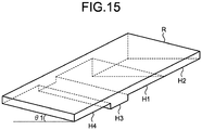
- the roof R covering the charging area A is provided with the reflecting planes, in the order of the second reflecting plane H2, the first reflecting plane H1, the third reflecting plane H3, the fourth reflecting plane H4, and the fifth reflecting plane H5 along the longitudinal direction of the charging area A.
- the roof or the bottom of the EV bus 1 may be provided with the reflecting planes, in the order of the second reflecting plane H2, the first reflecting plane H1, the third reflecting plane H3, the fourth reflecting plane H4, and the fifth reflecting plane H5 from the front side of the EV bus 1 along the traveling direction D1 of the EV bus 1.
- a charging system can detect the positional deviation of the EV bus 1 with respect to the charging area A in either of the case where the EV bus 1 has overrun the charging area A and advances again into the charging area A from the exit side of the charging area A, and the case where the EV bus 1 advances forward into the charging area A from the entrance side or the exit side thereof.
- the positional deviation detecting unit 105 displays front-rear deviation information 1703, such as an arrow, for making the deviation in the front-rear direction identifiable, on the display unit 106, as illustrated in FIG. 17 . If the above-described positional deviation are not detected (in other words, if the EV bus 1 has been precisely docked in the charging area A), the positional deviation detecting unit 105 displays stop instruction information 1704, such as characters, for instructing to stop the EV bus 1, on the display unit 106.
- front-rear deviation information 1703 such as an arrow
- a program to be executed by each of the charging systems of the first to ninth embodiments is provided by being incorporated in advance, for example, in a read-only memory (ROM).
- the program to be executed by each of the charging systems of the first to ninth embodiments may be provided by being recorded as a file in an installable or executable format on a computer-readable recording medium, such as a compact disc read-only memory (CD-ROM), a flexible disk (FD), a compact disc-recordable (CD-R), or a digital versatile disc (DVD).
- CD-ROM compact disc read-only memory
- FD flexible disk
- CD-R compact disc-recordable
- DVD digital versatile disc
- the program to be executed by each of the charging systems of the first to ninth embodiments may be stored on a computer connected to a network, such as the Internet, and provided by being downloaded through the network.
- the program to be executed by each of the charging systems of the first to ninth embodiments may be provided or distributed through a network, such as the Internet.
- the program to be executed by each of the charging systems of the first to ninth embodiments has a modular structure including the above-described units (such as the positional deviation detecting unit 105).
- a central processing unit CPU
Landscapes
- Engineering & Computer Science (AREA)
- Power Engineering (AREA)
- Mechanical Engineering (AREA)
- Physics & Mathematics (AREA)
- Transportation (AREA)
- Computer Networks & Wireless Communication (AREA)
- Electromagnetism (AREA)
- Remote Sensing (AREA)
- Radar, Positioning & Navigation (AREA)
- General Physics & Mathematics (AREA)
- Life Sciences & Earth Sciences (AREA)
- Sustainable Development (AREA)
- Sustainable Energy (AREA)
- Charge And Discharge Circuits For Batteries Or The Like (AREA)
- Electric Propulsion And Braking For Vehicles (AREA)
Abstract
Description
- Embodiments of the present invention relates to a charging device and a positional deviation detection method.
- For reduction of global warming and provision for depletion of oil resources, electric vehicles (EVs) driven by electrical energy have been introduced. The electric vehicles are also being introduced into public transportation. In each of the electric vehicles, a power storage functional unit, such as a battery, mounted on the electric vehicle needs to be charged with the electrical energy. An electric vehicle bus (EV bus) as an example of the electric vehicle can be efficiently operated by charging the power storage functional unit while passengers are getting on and off at a bus stop.
-
- Patent Literature 1: Japanese Patent Application Laid-open No.
2011-16514 - Patent Literature 2: Japanese Patent Application Laid-open No.
2005-289580 - A request is being made to enable automatic charging without manual operations for charging the power storage functional unit of the electric vehicle from a charger installed on the ground. For example, in the case where the charger is installed at the bus stop and the power storage functional unit is charged while the passengers are getting on and off the EV bus at the bus stop, the charging is desirably performed automatically, saving effort associated with the charging, because the driver of the EV bus has operations, for example, to check safety and collect fees from the passengers. However, to automate the charging of the power storage functional unit of the electric vehicle, the electric vehicle needs to be accurately stopped in a predefined area where the charging can be made by the charger.
- A charging device according to one embodiment includes a charging unit, a measuring unit, and a detecting unit. The charging unit charges a power storage functional unit included in a vehicle stopping in a rectangular predefined area. The measuring unit is capable of measuring a vertical distance to a point in a first plane that is provided in a first position serving as a roof or a bottom of the vehicle, and that has a gradient of a first angle with respect to a horizontal plane toward an orthogonal direction orthogonal to a traveling direction of the vehicle. The detecting unit detects an angle of inclination of the vehicle with respect to a longitudinal direction based on a first difference, a distance, and the first angle, the first difference being a difference between a first vertical distance to a first point in the first plane and a second vertical distance to a second point in the first plane having a position in the traveling direction different from that of the first point, the distance being a distance between the first point and the second point.
-
-
FIG. 1 is a diagram illustrating an exemplary configuration of a charging system according to a first embodiment of the present invention. -
FIG. 2 is an exemplary overhead view of a charging area in the charging system according to the first embodiment, as viewed from above. -
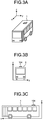
FIG. 3A is a diagram for explaining an example of an EV bus charged in the charging system according to the first embodiment. -
FIG. 3B is another diagram for explaining the example of the EV bus charged in the charging system according to the first embodiment. -
FIG. 3C is still another diagram for explaining the example of the EV bus charged in the charging system according to the first embodiment. -
FIG. 3D is still another diagram for explaining the example of the EV bus charged in the charging system according to the first embodiment. -
FIG. 3E is a diagram for explaining still another example of the EV bus charged in the charging system according to the first embodiment. -
FIG. 4 is a diagram illustrating an example of a first reflecting plane provided on a roof of the EV bus charged in the charging system according to the first embodiment. -
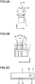
FIG. 5A is a diagram for explaining an example of detection processing of a positional deviation of the EV bus in the charging system according to the first embodiment. -
FIG. 5B is another diagram for explaining the example of the detection processing of the positional deviation of the EV bus in the charging system according to the first embodiment. -
FIG. 5C is still another diagram for explaining the example of the detection processing of the positional deviation of the EV bus in the charging system according to the first embodiment. -
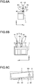
FIG. 6A is a diagram for explaining another example of the detection processing of the positional deviation of the EV bus in the charging system according to the first embodiment. -
FIG. 6B is another diagram for explaining the other example of the detection processing of the positional deviation of the EV bus in the charging system according to the first embodiment. -
FIG. 6C is still another diagram for explaining the other example of the detection processing of the positional deviation of the EV bus in the charging system according to the first embodiment. -
FIG. 7A is an exemplary diagram of a relation between points in the first reflecting plane to which vertical distances are measured in the charging system according to the first embodiment, as viewed from above the charging area. -
FIG. 7B is another exemplary diagram of the relation between the points in the first reflecting plane to which the vertical distances are measured in the charging system according to the first embodiment, as viewed from above the charging area. -
FIG. 8 is an exemplary diagram of the relation between the points in the first reflecting plane to which the vertical distances are measured in the charging system according to the first embodiment, as viewed from an exit side of the charging area. -
FIG. 9 is a diagram illustrating an exemplary configuration of a charging system according to a second embodiment of the present invention. -
FIG. 10 is a diagram illustrating an exemplary configuration of a charging system according to a third embodiment of the present invention. -
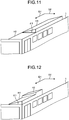
FIG. 11 is a diagram illustrating an example of reflecting planes provided on the roof of the EV bus charged in a charging system according to a fourth embodiment of the present invention. -
FIG. 12 is a diagram illustrating an example of reflecting planes provided on the roof of the EV bus charged in a charging system according to a fifth embodiment of the present invention. -
FIG. 13 is a diagram illustrating an example of reflecting planes provided on the roof of the EV bus charged in a charging system according to a seventh embodiment of the present invention. -
FIG. 14 is a diagram for explaining an example of a detection flow of the positional deviation of the EV bus in the charging system according to the seventh embodiment. -
FIG. 15 is a diagram for explaining an example of reflecting planes provided on the roof of the charging area in a charging system according to an eighth embodiment of the present invention. -
FIG. 16 is a diagram for explaining an example of a detection flow of the positional deviation of the EV bus in the charging system according to the eighth embodiment. -
FIG. 17 is a diagram illustrating an example of positional deviation information displayed on a display unit in charging systems according to the first to ninth embodiments. -
FIG. 18 is a diagram illustrating an exemplary charging method of the EV bus in the charging systems according to the first to ninth embodiments. - The following describes, using the accompanying drawings, charging systems to which a charging device and a positional deviation detection method according to embodiments of the present invention are applied.
-
FIG. 1 is a diagram illustrating an exemplary configuration of a charging system according to a first embodiment of the present invention. As illustrated inFIG. 1 , the charging system according to the present embodiment includes acharging unit 102, apower feeding unit 103, a first distance measuring instrument K1, a second distance measuring instrument K2, a positionaldeviation detecting unit 105, and adisplay unit 106. The chargingunit 102 charges a power storage functional unit, such as a battery, provided in an electric vehicle (EV) bus 1 (an example of a vehicle) stopping in a charging area A. In the present embodiment, the chargingunit 102 charges the power storage functional unit by feeding power to the power storage functional unit of theEV bus 1 through thepower feeding unit 103 provided so as to be movable to near apower receiving unit 104 provided on a roof of theEV bus 1. - The charging area A is a rectangular predefined area. In the present embodiment, the charging area A is a rectangular area having a longitudinal direction in a direction from an entrance of the charging area A toward an exit of the charging area A. Specifically, the length in the longitudinal direction of the charging area A is equal to a vehicle length of the EV bus 1 (such as 10 m) or a length obtained by adding a predetermined allowable deviation to the vehicle length of the
EV bus 1. The length in a lateral direction of the charging area A is equal to a vehicle width of the EV bus 1 (such as 2 m) or a length obtained by adding the predetermined allowable deviation to the vehicle width of theEV bus 1. The predetermined allowable deviation refers to a positional deviation allowable for theEV bus 1 in the charging area A when the power storage functional unit of theEV bus 1 stopping in the charging area A is charged. - The first and second distance measuring instruments K1 and K2 are examples of measuring units that are provided facing a first reflecting plane H1 (an example of a first plane) provided on the roof (an example of a first position) of the
EV bus 1, and that can measure vertical distances to points in the first reflecting plane H1. The first distance measuring instrument K1 (an example of a first measuring unit) can measure the vertical distance to a point in the first reflecting plane H1. The second distance measuring instrument K2 (an example of a second measuring unit) is provided closer than the first distance measuring instrument K1 to an entrance side of the charging area A, and can measure the vertical distance to another point in the first reflecting plane H1. In the present embodiment, the first and second distance measuring instruments K1 and K2 are provided above the first reflecting plane H1 by a structure such as a supporting pole (not illustrated), and are provided so as to be capable of measuring the vertical distances to the points on a line in the first reflecting plane H1 parallel to the longitudinal direction of the charging area A. In the present embodiment, each of the first and second distance measuring instruments K1 and K2 is, for example, a laser distance meter, and can measure the distance to an object, such as the first reflecting plane H1, at a level of accuracy of 1.0 mm or smaller. - The positional deviation detecting unit 105 (an example of a detecting unit) detects the positional deviation of the
EV bus 1 with respect to the charging area A (in the present embodiment, an inclination of theEV bus 1 with respect to the longitudinal direction of the charging area A) based on, for example, the vertical distances measured by the first and second distance measuring instruments K1 and K2. In the present embodiment, when the power storage functional unit of theEV bus 1 stopping in the charging area A is charged, the positionaldeviation detecting unit 105 stores therein the positional deviation of theEV bus 1 allowable in the charging area A (hereinafter, called an allowable positional deviation), such as the inclination of theEV bus 1 allowable with respect to the longitudinal direction of the charging area A. The positionaldeviation detecting unit 105 displays positional deviation information on the detected positional deviation of theEV bus 1 on thedisplay unit 106. In the present embodiment, thedisplay unit 106 is provided in a position in front of theEV bus 1 stopping in the charging area A and visible by a driver D of theEV bus 1, and can display various types of information, such as the positional deviation information. In the following description, theEV bus 1 will be described as precisely docked in the charging area A when the positional deviation detected by the positionaldeviation detecting unit 105 is equal to or smaller than the allowable positional deviation. - The following describes, using
FIGS. 2 and3A to 3E, theEV bus 1 charged in the charging system according to the present embodiment.FIG. 2 is an exemplary overhead view of the charging area in the charging system according to the first embodiment, as viewed from above.FIGS. 3A to 3E are diagrams for explaining examples of the EV bus charged in the charging system according to the first embodiment. - As illustrated in
FIG. 2 , in the charging system according to the present embodiment, the longitudinal direction of the charging area A is referred to as an x-axis direction, and the lateral direction of the charging area A is referred to as a y-axis direction. As illustrated inFIG. 3A , the vertical direction of the charging area A is referred to as a z-axis direction. -
FIG. 3B is a diagram of theEV bus 1 stopping in the charging area A, as viewed from an exit side of the charging area A.FIG. 3C is a diagram of theEV bus 1 stopping in the charging area A, as viewed from a lateral side.FIG. 3D is a diagram of theEV bus 1 stopping in the charging area A, as viewed from above.FIG. 3E is a diagram of theEV bus 1 stopping at an angle with respect to the longitudinal direction of the charging area A, as viewed from above. When theEV bus 1 has stopped in the charging area A as illustrated inFIG. 3E , the positionaldeviation detecting unit 105 detects an angle β (hereinafter, called an inclination angle) at which theEV bus 1 is inclined with respect to the longitudinal direction of the charging area A. - The following describes, using
FIG. 4 , an example of the first reflecting plane H1 provided on the roof of theEV bus 1 charged in the charging system according to the present embodiment.FIG. 4 is a diagram illustrating the example of the first reflecting plane provided on the roof of the EV bus charged in the charging system according to the first embodiment. - As illustrated in
FIG. 4 , the first reflecting plane H1 is a plane having a gradient of a first angle θ1 with respect to a horizontal plane in an orthogonal direction D2 orthogonal to a traveling direction D1 of theEV bus 1. In the present embodiment, a non-specular reflective member, such as a member of a diffusively reflective material, is preferably used as the first reflecting plane H1. In the present embodiment, the first reflecting plane H1 has a height difference of several centimeters to several tens of centimeters with respect to the roof of theEV bus 1. In the present embodiment, the first reflecting plane H1 is preferably a plane having an inclination gradually increasing in height with respect to the horizontal plane from inside toward outside the roof of theEV bus 1. This configuration can prevent light emitted from, for example, the first and second distance measuring instruments K1 and K2 toward the first reflecting plane H1 from being reflected outward of theEV bus 1. Therefore, the light reflected by the first reflecting plane H1 can be prevented from entering eyes of passengers of theEV bus 1. - The following describes, using
FIGS. 5A to 5C ,6A to 6C ,7A and 7B , and8 , detection processing of the positional deviation performed by the positionaldeviation detecting unit 105 of the charging system according to the present embodiment.FIGS. 5A to 5C and6A to 6C are diagrams for explaining examples of the detection processing of the positional deviation of the EV bus in the charging system according to the first embodiment.FIGS. 7A and 7B are exemplary diagrams of a relation between points in the first reflecting plane to which the vertical distances are measured in the charging system according to the first embodiment, as viewed from above the charging area.FIG. 8 is an exemplary diagram of the relation between the points in the first reflecting plane to which the vertical distances are measured in the charging system according to the first embodiment, as viewed from the exit side of the charging area. -
FIGS. 5A and6A are diagrams of theEV bus 1, as viewed from the exit side of the charging area A.FIGS. 5B and6B are side views of theEV bus 1.FIGS. 5C and6C are diagrams of theEV bus 1, as viewed from above the charging area A. As illustrated inFIGS. 5A to 5C and6A to 6C , the first and second distance measuring instruments K1 and K2 measure the vertical distances to respective points P1 and P2 (examples of a first point and a second point) in the first reflecting plane H1 that are located in positions different from each other in the traveling direction D1 of theEV bus 1. In the present embodiment, the first and second distance measuring instruments K1 and K2 measure distances to points in the first reflecting plane H1 that are located on a line parallel to the longitudinal direction of the charging area A. Therefore, as illustrated inFIGS. 5A, 5B, and 5C , when theEV bus 1 has been precisely docked without being inclined with respect to the longitudinal direction of the charging area A, a vertical distance h1 to the point P1 in the first reflecting plane H1 measured by the first distance measuring instrument K1 is equal to a vertical distance h2 to the point P2 in the first reflecting plane H1 measured by the second distance measuring instrument K2. - In contrast, as illustrated in
FIGS. 6A and 6B , when theEV bus 1 has stopped while being inclined at the inclination angle β with respect to the longitudinal direction of the charging area A, the point P1 and the point P2 in the first reflecting plane H1 are at different heights from the roof of theEV bus 1. Therefore, as illustrated inFIGS. 6A, 6B, and 6C , when theEV bus 1 has stopped at an angle with respect to the longitudinal direction of the charging area A, the vertical distance h1 to the point P1 measured by the first distance measuring instrument K1 differs from the vertical distance h2 to the point P2 measured by the second distance measuring instrument K2. - Accordingly, the positional
deviation detecting unit 105 detects the inclination angle β of theEV bus 1 with respect to the longitudinal direction of the charging area A based on the difference (an example of a first difference) between the vertical distance h1 (an example of a first vertical distance) to the point P1 (the example of the first point) measured by the first distance measuring instrument K1 and the vertical distance h2 (an example of a second vertical distance) to the point P2 (the example of the second point) measured by the second distance measuring instrument K2, a distance L between the point P1 and the point P2, and the first angle θ1. Since the distance L between the point P1 and the point P2 and the first angle θ1 are preset values, the inclination angle β of theEV bus 1 can be detected using trigonometric functions if the difference between the vertical distance h1 and the vertical distance h2 can be obtained. - Specifically, when detecting the inclination angle β of the
EV bus 1, the positionaldeviation detecting unit 105 acquires the distance L between the point P1 and the point P2 (in the present embodiment, the distance between the first distance measuring instrument K1 and the second distance measuring instrument K2), as illustrated inFIG. 7A . A straight line connecting the point P1 to the point P2 intersects the longitudinal direction of the charging area A (x-axis) at the inclination angle β of theEV bus 1. Consequently, as illustrated inFIG. 7B , an orthogonal line m drawn from the point P2 to the longitudinal direction of the charging area A (x-axis) is represented by Expression (1) below.
- When the
EV bus 1 has stopped at an angle with respect to the longitudinal direction of the charging area A, the vertical distance h1 to the point P1 measured by the first distance measuring instrument K1 and the vertical distance h2 to the point P2 measured by the second distance measuring instrument K2 have a difference h therebetween, as illustrated inFIG. 8 . The difference h is represented by Expression (2) below.
- According to Expression (2) above, the inclination angle β can be obtained by Expression (3) below.

- In the present embodiment, the positional
deviation detecting unit 105 determines whether the detected inclination angle β is larger than a predetermined angle included in the allowable positional deviation. The predetermined angle is an upper limit angle of the inclination angle β at which thecharging unit 102 can charge the power storage functional unit of theEV bus 1. If the detected inclination angle β exceeds the predetermined angle, the positionaldeviation detecting unit 105 detects the positional deviation of theEV bus 1 with respect to the charging area A. The positionaldeviation detecting unit 105 displays the positional deviation information (such as the direction of movement of theEV bus 1 for correcting the inclination thereof with respect to the longitudinal direction of the charging area A and the detected inclination angle β) on thedisplay unit 106. This display allows the driver D of theEV bus 1 to correct the inclination angle β of theEV bus 1 with respect to the charging area A. If, instead, the detected inclination angle β is equal to or smaller than the predetermined angle, the positionaldeviation detecting unit 105 does not detect the positional deviation of theEV bus 1 with respect to the charging area A, and displays information indicating that theEV bus 1 has been precisely docked in the charging area A as the positional deviation information on thedisplay unit 106. - In this manner, since the charging system according to the first embodiment can accurately detect the inclination angle β of the
EV bus 1 with respect to the charging area A, the driver D of theEV bus 1 can more accurately stop theEV bus 1 with respect to the charging area A. - In the present embodiment, the vertical distances to the respective two points in the first reflecting plane H1 are measured using the two distance measuring instruments of the first and second distance measuring instruments K1 and K2 as the examples of the measuring units. However, the vertical distances to the respective two points in the first reflecting plane H1 may be measured using one distance measuring instrument as an example of a measuring unit. In this case, in the process in which the
EV bus 1 moves in the charging area A, the one distance measuring instrument measures the vertical distances to the respective two points in the first reflecting plane H1 that are located in positions different from each other in the traveling direction D1 of theEV bus 1. - When the first reflecting plane H1 is provided on the roof of the
EV bus 1, the first reflecting plane H1 is preferably provided so as to cover various devices, such as an outdoor unit of an air conditioner and a device for charging, provided on the roof of theEV bus 1. This configuration can prevent the various devices provided on the roof of theEV bus 1 from coming into contact with, for example, a roadside tree. - A second embodiment of the present invention is an example in which the first reflecting plane is provided at the bottom of the EV bus. In the following description, the same configurations as those of the first embodiment will not be described.
-
FIG. 9 is a diagram illustrating an exemplary configuration of a charging system according to the second embodiment. As illustrated inFIG. 9 , in the present embodiment, the first reflecting plane H1 is provided at the bottom (an example of the first position) of theEV bus 1. Hence, the first and second distance measuring instruments K1 and K2 are provided facing the bottom of theEV bus 1 so as to be capable of measuring the vertical distances to points in the first reflecting plane H1 that are located in positions different from each other in the traveling direction D1 of theEV bus 1. In the present embodiment, the first and second distance measuring instruments K1 and K2 are embedded in a road surface of the charging area A, and can measure the vertical distances to the points on a line in the first reflecting plane H1 parallel to the longitudinal direction of the charging area A. In the same manner as in the first embodiment, the positionaldeviation detecting unit 105 uses, for example, the vertical distances measured by the first and second distance measuring instruments K1 and K2 to detect the inclination angle β of theEV bus 1. - In this manner, also in the case where the first reflecting plane H1 is provided at the bottom of the
EV bus 1, with the charging system according to the second embodiment, the same operational effect as that of the first embodiment can be obtained. - A third embodiment of the present invention is an example in which the first reflecting plane is provided above the EV bus stopping in the charging area. In the following description, the same configurations as those of the first embodiment will not be described.
-
FIG. 10 is a diagram illustrating an exemplary configuration of a charging system according to the third embodiment. As illustrated inFIG. 10 , in the charging system according to the present embodiment, the first reflecting plane H1 is provided on a roof R covering at least the charging area A. Hence, the first and second distance measuring instruments K1 and K2 are provided on the roof of theEV bus 1 so as to be capable of measuring the vertical distances to points in the first reflecting plane H1 that are located in positions different from each other with respect to the longitudinal direction of the charging area A. In the present embodiment, the second distance measuring instrument K2 is provided on an aft side of theEV bus 1 relative to the first distance measuring instrument. In the present embodiment, the first and second distance measuring instruments K1 and K2 are provided on a line parallel to the traveling direction of theEV bus 1. - In the present embodiment, the positional
deviation detecting unit 105 is provided in theEV bus 1. In the same manner as in the first embodiment, the positionaldeviation detecting unit 105 uses, for example, the vertical distances measured by the first and second distance measuring instruments K1 and K2 to detect the inclination angle β of theEV bus 1. The positionaldeviation detecting unit 105 determines whether the detected inclination angle β is larger than the predetermined angle. If the detected inclination angle β exceeds the predetermined angle, the positionaldeviation detecting unit 105 displays, for example, the direction of movement of theEV bus 1 for correcting the inclination angle β and the detected inclination angle β as the positional deviation information on thedisplay unit 106. If, instead, the detected inclination angle β is equal to or smaller than the predetermined angle, the positionaldeviation detecting unit 105 displays the information indicating that theEV bus 1 has been precisely docked in the charging area A as the positional deviation information on thedisplay unit 106. - In this manner, also in the case where the first reflecting plane H1 is provided above the
EV bus 1 stopping in the charging area A, with the charging system according to the third embodiment, the same operational effect as that of the first embodiment can be obtained. Since the first reflecting plane H1 can be used also as a roof for rain protection at a bus stop provided with the charging area A, an increase in cost due to the provision of the first reflecting plane H1 can be restrained, and the first reflecting plane H1 can be provided causing no sense of discomfort about the surrounding landscape. - A fourth embodiment of the present invention is an example in which vertical distances are measured to points in a second reflecting plane on the roof or the bottom of the EV bus that is provided on a fore side in the traveling direction of the EV bus than the first reflecting plane and that has no gradient, and a positional deviation of the EV bus in the lateral direction of the charging area A is detected using differences between vertical distances to points in the first reflecting plane and vertical distances to points in the second reflecting plane. In the following description, the same portions as those of the first embodiment will not be described.
-
FIG. 11 is a diagram illustrating an example of the reflecting planes provided on the roof of the EV bus charged in a charging system according to the fourth embodiment. As illustrated inFIG. 11 , in the present embodiment, theEV bus 1 includes, on the roof of theEV bus 1, a second reflecting plane H2 that is provided on the fore side in the traveling direction D1 relative to the first reflecting plane H1 and that has no gradient. A non-specular reflective member, such as a member of a diffusively reflective material, is preferably used as the second reflecting plane H2. - In the present embodiment, when the
EV bus 1 has advanced into the charging area A, the first and second distance measuring instruments K1 and K2 first measure the vertical distances to the second reflecting plane H2. The positionaldeviation detecting unit 105 stores therein the vertical distance to the second reflecting plane H2 measured by the first distance measuring instrument K1 as a reference distance href1. The positionaldeviation detecting unit 105 stores therein the vertical distance to the second reflecting plane H2 measured by the second distance measuring instrument K2 as a reference distance href2. Since the second reflecting plane H2 has no gradient (in other words, since the second reflecting plane H2 is horizontal), the reference distance href1 is equal to the reference distance href2. - Subsequently, when the
EV bus 1 has further advanced into the charging area A and the second distance measuring instrument K2 is located over the first reflecting plane H1, the first distance measuring instrument K1 measures the vertical distance h1 to a point in the second reflecting plane H2, and the second distance measuring instrument K2 measures the vertical distance h2 to a point in the first reflecting plane H1. As a result, the vertical distance h2 measured by the second distance measuring instrument K2 is smaller than the vertical distance h1 measured by the first distance measuring instrument K1. Thereafter, when theEV bus 1 has further advanced into the charging area A and the first and second distance measuring instruments K1 and K2 are located over the first reflecting plane H1, the first and second distance measuring instruments K1 and K2 together measure the vertical distances h1 and h2 to points in the first reflecting plane H1. - When the vertical distance h1 measured by the first distance measuring instrument K1 has decreased to be smaller than the reference distance ref1, or when the vertical distance h2 measured by the second distance measuring instrument K2 has decreased to be smaller than the reference distance ref2, the positional
deviation detecting unit 105 obtains at least either one of a difference h1y between the vertical distance h1 and the reference distance ref1 and a difference h2y between the vertical distance h2 and the reference distance ref2. In other words, the positionaldeviation detecting unit 105 obtains the difference h1y between the reference distance href1 and the vertical distance h1 to a point in the first reflecting plane H1 having the same position in the orthogonal direction D2 as the position in the second reflecting plane H2 where the reference distance href1 has been measured. Otherwise, the positionaldeviation detecting unit 105 obtains the difference h2y between the reference distance ref2 and the vertical distance h2 to a point in the first reflecting plane H1 having the same position in the orthogonal direction D2 as the position in the second reflecting plane H2 where the reference distance href2 has been measured. - Subsequently, the positional
deviation detecting unit 105 calculates a positional deviation Δy1 (hereinafter, called a right-left deviation) of theEV bus 1 with respect to the lateral direction of the charging area A based on the difference h1y, a value hp of the difference h1y (hereinafter, called a reference value) in the case where theEV bus 1 has stopped in the charging area A (in the case where theEV bus 1 has been precisely docked in the charging area A), and the first angle θ1. Specifically, the positionaldeviation detecting unit 105 obtains the right-left deviation Δy1 using Expression (4) below.
- The positional
deviation detecting unit 105 calculates a right-left deviation Δy2 of theEV bus 1 with respect to the lateral direction of the charging area A based on the difference h2y, the reference value hp, and the first angle θ1. Specifically, the positionaldeviation detecting unit 105 obtains the right-left deviation Δy2 using Expression (5) below.
- If at least either one of the detected right-left deviations Δy1 and Δy2 is larger than a predetermined amount of deviation included in the allowable positional deviation, the positional
deviation detecting unit 105 displays the direction of movement of theEV bus 1 for correcting the right-left deviations Δy1 and Δy2 and the detected right-left deviations Δy1 and Δy2 as the positional deviation information on thedisplay unit 106. If, instead, both of the detected right-left deviations Δy1 and Δy2 are equal to or smaller than the predetermined amount of deviation, the positionaldeviation detecting unit 105 displays the information indicating that theEV bus 1 has been precisely docked in the charging area A as the positional deviation information on thedisplay unit 106. - In this manner, since the charging system according to the fourth embodiment can accurately detect the right-left deviations Δy1 and Δy2 of the
EV bus 1 with respect to the charging area A, the driver D of theEV bus 1 can more accurately stop theEV bus 1 with respect to the charging area A. - A fifth embodiment of the present invention is an example in which vertical distances are measured to points in a third reflecting plane on the roof or the bottom of the EV bus that is provided on an aft side in the traveling direction of the EV bus relative to the first reflecting plane and that is parallel to the first reflecting plane, and a determination is made as to whether the EV bus has the positional deviation with respect to the longitudinal direction of the charging area, using differences between vertical distances to points in the first reflecting plane and vertical distances to points in the third reflecting plane. In the following description, the same configurations as those of the first embodiment will not be described.
-
FIG. 12 is a diagram illustrating an example of the reflecting planes provided on the roof of the EV bus charged in a charging system according to the fifth embodiment. As illustrated inFIG. 12 , in the present embodiment, theEV bus 1 includes, on the roof of theEV bus 1, a third reflecting plane H3 (an example of a third plane) that is provided on the aft side in the traveling direction D1 relative to the first reflecting plane H1 and that is parallel to the first reflecting plane H1. The difference of the third reflecting plane H3 relative to the first reflecting plane H1 (an example of a third difference) in the vertical direction from the roof of theEV bus 1 is larger than an upper limit hq (hereinafter, called a difference upper limit) of the difference between the vertical distances (an example of the first difference) to the two points in the first reflecting plane H1 that is caused by the inclination angle β of theEV bus 1. In the present embodiment, the difference upper limit hq is a value allowing for an error in the difference between the vertical distances to the two points in the first reflecting plane H1. A non-specular reflective member, such as a member of a diffusively reflective material, is preferably used as the third reflecting plane H3. In the present embodiment, the first and second distance measuring instruments K1 and K2 are provided in positions where vertical distances to points in the third reflecting plane H3 can be measured when theEV bus 1 has been precisely docked in the charging area A. - In the present embodiment, when the
EV bus 1 has advanced into the charging area A, the vertical distance measured by the second distance measuring instrument K2 first changes to the vertical distance to a point in the first reflecting plane H1. The positionaldeviation detecting unit 105 stores therein the vertical distance measured by the second distance measuring instrument K2 as a reference vertical distance. Thereafter, the positionaldeviation detecting unit 105 waits until theEV bus 1 further advances into the charging area A to change the vertical distance measured by the second distance measuring instrument K2. If the difference upper limit hq is reached by the difference between the reference vertical distance and the vertical distance measured by the second distance measuring instrument K2 after the reference vertical distance has been measured, the positionaldeviation detecting unit 105 determines that the positional deviation of theEV bus 1 with respect to the longitudinal direction of the charging area A has been eliminated. - Otherwise, the positional
deviation detecting unit 105 stores therein the vertical distance to a point in the first reflecting plane H1 measured by the first distance measuring instrument K1 as the reference vertical distance. Thereafter, the positionaldeviation detecting unit 105 waits until theEV bus 1 further advances into the charging area A to change the vertical distance measured by the first distance measuring instrument K1. The positionaldeviation detecting unit 105 may determine that the positional deviation of theEV bus 1 with respect to the longitudinal direction of the charging area A has been eliminated if the difference upper limit hq is reached by the difference between the reference vertical distance and the vertical distance measured by the first distance measuring instrument K1 after the reference vertical distance has been measured. - If the positional
deviation detecting unit 105 determines that the positional deviation of theEV bus 1 with respect to the longitudinal direction of the charging area A has been eliminated, the positionaldeviation detecting unit 105 displays the information indicating that the EV bus has been precisely docked in the charging area A as the positional deviation information on thedisplay unit 106. - In this manner, since the charging system according to the fifth embodiment can accurately determine that the positional deviation of the
EV bus 1 with respect to the longitudinal direction of the charging area A has been eliminated, the driver D of theEV bus 1 can more accurately stop theEV bus 1 with respect to the charging area A. - A sixth embodiment of the present invention is an example in which the position of the EV bus with respect to the longitudinal direction of the charging area is determined to have come close to a position where the charging unit can charge the EV bus in the charging area if the difference upper limit is reached by the difference between the reference vertical distance measured by the second distance measuring instrument and the vertical distance measured by the second distance measuring instrument after the reference vertical distance has been measured. In the following description, the same configurations as those of the fifth embodiment will not be described.
- In the present embodiment, when the
EV bus 1 has advanced into the charging area A, the vertical distance measured by the second distance measuring instrument K2 first changes to the vertical distance to a point in the first reflecting plane H1. The positionaldeviation detecting unit 105 stores therein the vertical distance measured by the second distance measuring instrument K2 as the reference vertical distance. Thereafter, when theEV bus 1 has further advanced into the charging area A, the positionaldeviation detecting unit 105 detects that the vertical distance measured by the first distance measuring instrument K1 changes to the vertical distance to a point in the first reflecting plane H1. The positionaldeviation detecting unit 105 stores therein the vertical distance measured by the first distance measuring instrument K1 as the reference vertical distance. - The positional
deviation detecting unit 105 waits until theEV bus 1 further advances into the charging area A to change the vertical distance measured by the second distance measuring instrument K2. If the difference upper limit hq is reached by the difference between the reference vertical distance measured by the second distance measuring instrument K2 and the vertical distance measured by the second distance measuring instrument K2 after the reference vertical distance has been measured, the positionaldeviation detecting unit 105 detects that the difference between the position of theEV bus 1 with respect to the longitudinal direction of the charging area A and the position (hereinafter, called a precise docking position) where the chargingunit 102 can perform the charging in the charging area A is equal to or smaller than a predetermined threshold. At that time, the positionaldeviation detecting unit 105 displays information indicating that the position of theEV bus 1 with respect to the longitudinal direction of the charging area A has come close to the precise docking position as the positional deviation information on thedisplay unit 106. - The positional
deviation detecting unit 105 waits until theEV bus 1 further advances into the charging area A to change the vertical distance measured by the first distance measuring instrument K1. If the difference upper limit hq is reached by the difference between the reference vertical distance measured by the first distance measuring instrument K1 and the vertical distance measured by the first distance measuring instrument K1 after the reference vertical distance has been measured, the positionaldeviation detecting unit 105 determines that the positional deviation of theEV bus 1 with respect to the longitudinal direction of the charging area A has been eliminated. - In this manner, since a charging system according to the sixth embodiment can accurately determine that the positional deviation of the
EV bus 1 with respect to the longitudinal direction of the charging area A has decreased and that the positional deviation has been eliminated, the driver D of theEV bus 1 can more accurately stop theEV bus 1 with respect to the charging area A. - A seventh embodiment of the present invention is an example in which the second distance measuring instrument can measure the vertical distance to a point in a fourth reflecting plane on the roof or the bottom of the EV bus that is provided on an aft side in the traveling direction of the EV bus relative to the third reflecting plane and that is parallel to the first reflecting plane, and the positional deviation of the EV bus with respect to the longitudinal direction of the charging area A is detected if the difference upper limit is reached by the difference between the vertical distance measured by the first distance measuring instrument and the vertical distance measured by the second distance measuring instrument and then the vertical distance measured by the second distance measuring instrument changes before the charging
unit 102 performs the charging. In the following description, the same configurations as those of the sixth embodiment will not be described. -
FIG. 13 is a diagram illustrating an example of the reflecting planes provided on the roof of the EV bus charged in a charging system according to the seventh embodiment. As illustrated inFIG. 13 , in the present embodiment, theEV bus 1 includes, on the roof of theEV bus 1, a fourth reflecting plane H4 (an example of a fourth plane) that is provided on an aft side in the traveling direction D1 than the third reflecting plane H3 and that is parallel to the first reflecting plane H1. The position of the fourth reflecting plane H4 in the vertical direction from the roof of theEV bus 1 differs from that of at least the third reflecting plane H3. In the present embodiment, the position of the fourth reflecting plane H4 in the vertical direction from the roof of theEV bus 1 differs from those of all of the first reflecting plane H1, the second reflecting plane H2, and the third reflecting plane H3. A non-specular reflective member, such as a member of a diffusively reflective material, is preferably used as the fourth reflecting plane H4. - In the present embodiment, if the positional deviation of the
EV bus 1 with respect to the longitudinal direction of the charging area A is determined to have been eliminated and then the vertical distance measured by the second distance measuring instrument K2 changes before the chargingunit 102 charges the power storage functional unit of theEV bus 1, the positionaldeviation detecting unit 105 detects that the position of theEV bus 1 with respect to the longitudinal direction of the charging area A has passed through the precise docking position. In this manner, an overrun of theEV bus 1 with respect to the charging area A can be detected. At that time, the positionaldeviation detecting unit 105 displays information indicating that the position of theEV bus 1 has overrun the charging area A on thedisplay unit 106. - The following describes, using
FIGS. 13 and14 , a detection flow of the positional deviation of theEV bus 1 in the charging system according to the present embodiment.FIG. 14 is a diagram for explaining an example of the detection flow of the positional deviation of the EV bus in the charging system according to the seventh embodiment. In the present embodiment, as illustrated inFIG. 13 , theEV bus 1 includes, on the roof of theEV bus 1, the second reflecting plane H2, the first reflecting plane H1, the third reflecting plane H3, and the fourth reflecting plane H4, in this order from the front side in the traveling direction D1. - As illustrated in
FIG. 14 , the first and second distance measuring instruments K1 and K2 measure vertical distances to the ground surface until theEV bus 1 comes close to the charging area A. After theEV bus 1 passes through the entrance of the charging area A, the second distance measuring instrument K2 measures the vertical distance to a point in the second reflecting plane H2 provided on the roof of theEV bus 1. When theEV bus 1 has further advanced into the charging area A, the first and second distance measuring instruments K1 and K2 together measure vertical distances to points in the second reflecting plane H2. The positionaldeviation detecting unit 105 stores therein the vertical distance to the second reflecting plane H2 measured by the first distance measuring instrument K1 (reference distance Href1) and the vertical distance to the second reflecting plane H2 measured by the second distance measuring instrument K2 (reference distance Href2) (Step S1). - Subsequently, when the
EV bus 1 has further advanced into the charging area A and the second distance measuring instrument K2 is located over the first reflecting plane H1, the positionaldeviation detecting unit 105 obtains the difference h2y between the vertical distance h2 measured by the second distance measuring instrument K2 and the reference distance ref2. The positionaldeviation detecting unit 105 detects the deviation (right-left deviation) of theEV bus 1 with respect to the lateral direction of the charging area A based on the difference h2y, the reference value hp, and the first angle θ1 (Step S2). The positionaldeviation detecting unit 105 displays the positional deviation information indicating the detected right-left deviation on thedisplay unit 106. This display allows the driver D of theEV bus 1 to check the positional deviation information displayed on thedisplay unit 106 and correct the right-left deviation of theEV bus 1. - Subsequently, when the
EV bus 1 has further advanced into the charging area A and the first and second distance measuring instruments K1 and K2 are located over the first reflecting plane H1, the positionaldeviation detecting unit 105 detects the inclination angle β (rotational deviation) of theEV bus 1 with respect to the longitudinal direction of the charging area A based on the difference between the vertical distance h1 to the point P1 in the first reflecting plane H1 measured by the first distance measuring instrument K1 and the vertical distance h2 to the point P2 in the first reflecting plane H1 measured by the second distance measuring instrument K2, the distance L between the point P1 and the point P2, and the first angle θ1 (Step S3). At that time, the positionaldeviation detecting unit 105 obtains the difference h1y between the vertical distance h1 measured by the first distance measuring instrument K1 and the reference distance ref1. The positionaldeviation detecting unit 105 may detect the deviation (right-left deviation) of theEV bus 1 with respect to the lateral direction of the charging area A based on the difference h1y, the reference value hp, and the first angle θ1 (Step S3). The positionaldeviation detecting unit 105 displays the positional deviation information indicating the rotational deviation and the right-left deviation thus detected on thedisplay unit 106. This display allows the driver D of theEV bus 1 to check the information displayed on thedisplay unit 106 and correct the rotational deviation and the right-left deviation of theEV bus 1. - When the
EV bus 1 has further advanced into the charging area A and the second distance measuring instrument K2 is located over the third reflecting plane H3 to change the vertical distance measured by the second distance measuring instrument K2, the positionaldeviation detecting unit 105 determines whether the difference upper limit hq is reached by the difference between the vertical distance (reference vertical distance) to the point in the first reflecting plane H1 measured by the second distance measuring instrument K2 and the vertical distance measured by the second distance measuring instrument K2 after the reference vertical distance has been measured. If the difference upper limit hq is reached by the difference between the reference vertical distance measured by the second distance measuring instrument K2 and the vertical distance (vertical distance to the point in the third reflecting plane H3) measured by the second distance measuring instrument K2 after the reference vertical distance has been measured, the positionaldeviation detecting unit 105 determines that the position of theEV bus 1 with respect to the longitudinal direction (front-rear direction) of the charging area A has come close to the precise docking position (Step S4). The positionaldeviation detecting unit 105 displays the positional deviation information indicating that the position of theEV bus 1 with respect to the longitudinal direction (front-rear direction) of the charging area A has come close to the precise docking position and indicating the rotational deviation and the right-left deviation detected at Step S3, on thedisplay unit 106. This display allows the driver D of theEV bus 1 to check that the positional deviation of theEV bus 1 with respect to the longitudinal direction of the charging area A has decreased to a small value. - When the
EV bus 1 has further advanced into the charging area A and the first and second distance measuring instruments K1 and K2 are located over the third reflecting plane H3, the positionaldeviation detecting unit 105 determines whether the difference upper limit hq is reached by the difference between the vertical distance (reference vertical distance) to the point in the first reflecting plane H1 measured by the first distance measuring instrument K1 and the vertical distance measured by the first distance measuring instrument K1 after the reference vertical distance has been measured. If the difference upper limit hq is reached by the difference between the reference vertical distance measured by the first distance measuring instrument K1 and the vertical distance (vertical distance to the point in the third reflecting plane H3) measured by the first distance measuring instrument K1 after the reference vertical distance has been measured, the positionaldeviation detecting unit 105 determines that the positional deviation of theEV bus 1 with respect to the longitudinal direction of the charging area A has been eliminated (in other words, theEV bus 1 has been precisely docked with respect to the front-rear direction of the charging area A) (Step S5). The positionaldeviation detecting unit 105 displays the positional deviation information indicating that theEV bus 1 has been precisely docked with respect to the longitudinal direction of the charging area A and indicating the rotational deviation and the right-left deviation detected at Step S3, on thedisplay unit 106. This display allows the driver D of theEV bus 1 to check that theEV bus 1 has been precisely docked with respect to the front-rear direction of the charging area A. - Thereafter, if, before the charging
unit 102 performs the charging, the driver D of theEV bus 1 moves theEV bus 1 in the longitudinal direction of the charging area A by mistake and the second distance measuring instrument K2 is located over the fourth reflecting plane H4 to change the vertical distance measured by the second distance measuring instrument K2, the positionaldeviation detecting unit 105 detects the positional deviation of theEV bus 1 with respect to the longitudinal direction (front-rear direction) of the charging area A (in other words, that theEV bus 1 is no longer precisely docked with respect to the front-rear direction of the charging area A) (Step S6). The positionaldeviation detecting unit 105 displays the positional deviation information indicating that theEV bus 1 is no longer precisely docked with respect to the front-rear direction of the charging area A and indicating the rotational deviation and the right-left deviation detected at Step S3, on thedisplay unit 106. This display allows the driver D of theEV bus 1 to check that the position of theEV bus 1 has started to deviate with respect to the front-rear direction of the charging area A. - Otherwise, the positional
deviation detecting unit 105 may detect the positional deviation of theEV bus 1 with respect to the longitudinal direction (front-rear direction) of the charging area A (in other words, that theEV bus 1 has overrun the position where the charging can be performed, with respect to the front-rear direction of the charging area A) if the driver D of theEV bus 1 moves theEV bus 1 and the first distance measuring instrument K1 is located over the fourth reflecting plane H4 to change the vertical distance measured by the first distance measuring instrument K1 (Step S7). The positionaldeviation detecting unit 105 displays the positional deviation information indicating that theEV bus 1 has overrun the position where the charging can be performed, with respect to the front-rear direction of the charging area A, and indicating the rotational deviation and the right-left deviation detected at Step S3, on thedisplay unit 106. This display allows the driver D of theEV bus 1 to check that theEV bus 1 has overrun the position where the charging can be performed, with respect to the front-rear direction of the charging area A. - In this manner, since the charging system according to the seventh embodiment can accurately detect the overrun of the
EV bus 1 in the longitudinal direction of the charging area A, the driver D of theEV bus 1 can more accurately stop theEV bus 1 with respect to the charging area A. - An eighth embodiment of the present invention is an example in which the first reflecting plane, the second reflecting plane, the third reflecting plane, and the fourth reflecting plane are provided above the EV bus stopping in the charging area. In the following description, the same configurations as those of the seventh embodiment will not be described.
-
FIG. 15 is a diagram for explaining an example of the reflecting planes provided on the roof of the charging area in a charging system according to the eighth embodiment. As illustrated inFIG. 15 , in the present embodiment, the roof R covering the charging area A includes the second reflecting plane H2, the first reflecting plane H1, the third reflecting plane H3, and the fourth reflecting plane H4, in this order from the entrance side for theEV bus 1 into the charging area A, along the longitudinal direction of the charging area A. In the present embodiment, in the same manner as in the third embodiment, the roof of theEV bus 1 is provided with the first and second distance measuring instruments K1 and K2. - In the same manner as in the seventh embodiment, the positional
deviation detecting unit 105 uses the vertical distances to the points in the respective reflecting planes measured by the first and second distance measuring instruments K1 and K2 to detect the deviation of theEV bus 1 with respect to the lateral direction of the charging area A, the inclination of theEV bus 1 with respect to the longitudinal direction of the charging area A, the positional deviation of theEV bus 1 with respect to the longitudinal direction of the charging area A, and the overrun of theEV bus 1 with respect to the longitudinal direction of the charging area A. - The following describes, using
FIG. 16 , a detection flow of the positional deviation of theEV bus 1 in the charging system according to the present embodiment. -
FIG. 16 is a diagram for explaining an example of the detection flow of the positional deviation of the EV bus in the charging system according to the eighth embodiment. - As illustrated in
FIG. 16 , during a period until theEV bus 1 comes close to the charging area A, the vertical distances measured by the first and second distance measuring instruments K1 and K2 provided on the roof of theEV bus 1 are infinite. After theEV bus 1 passes through the entrance of the charging area A, the first distance measuring instrument K1 measures the vertical distance to a point in the second reflecting plane H2 provided on the roof of theEV bus 1. When theEV bus 1 has further advanced into the charging area A, the first and second distance measuring instruments K1 and K2 together measure vertical distances to points in the second reflecting plane H2. The positionaldeviation detecting unit 105 stores therein the vertical distance to the second reflecting plane H2 measured by the first distance measuring instrument K1 (reference distance Href1) and the vertical distance to the second reflecting plane H2 measured by the second distance measuring instrument K2 (reference distance Href2) (Step S11). - Subsequently, when the
EV bus 1 has further advanced into the charging area A and the first distance measuring instrument K1 is located under the first reflecting plane H1, the positionaldeviation detecting unit 105 obtains the difference h1y between the vertical distance h1 measured by the first distance measuring instrument K1 and the reference distance ref1. The positionaldeviation detecting unit 105 detects the deviation (right-left deviation) of theEV bus 1 with respect to the lateral direction of the charging area A based on the difference h1y, the reference value hp, and the first angle θ1 (Step S12). The positionaldeviation detecting unit 105 displays the positional deviation information indicating the detected right-left deviation on thedisplay unit 106. This display allows the driver D of theEV bus 1 to check the positional deviation information displayed on thedisplay unit 106 and correct the right-left deviation of theEV bus 1. - Subsequently, when the
EV bus 1 has further advanced into the charging area A and the second distance measuring instrument K2 is located under the first reflecting plane H1, the positionaldeviation detecting unit 105 detects the inclination angle β (rotational deviation) of theEV bus 1 with respect to the longitudinal direction of the charging area A based on the difference between the vertical distance h1 to the point P1 in the first reflecting plane H1 measured by the first distance measuring instrument K1 and the vertical distance h2 to the point P2 in the first reflecting plane H1 measured by the second distance measuring instrument K2, the distance L between the point P1 and the point P2, and the first angle θ1 (Step S13). At that time, the positionaldeviation detecting unit 105 obtains the difference h2y between the vertical distance h2 measured by the second distance measuring instrument K2 and the reference distance ref2. The positionaldeviation detecting unit 105 may detect the deviation (right-left deviation) of theEV bus 1 with respect to the lateral direction of the charging area A based on the difference h2y, the reference value hp, and the first angle θ1 (Step S13). The positionaldeviation detecting unit 105 displays the positional deviation information indicating the rotational deviation and the right-left deviation thus detected on thedisplay unit 106. This display allows the driver D of theEV bus 1 to check the positional deviation information displayed on thedisplay unit 106 and correct the rotational deviation and the right-left deviation of theEV bus 1. - When the
EV bus 1 has further advanced into the charging area A and the first distance measuring instrument K1 is located under the third reflecting plane H3 to change the vertical distance measured by the first distance measuring instrument K1, the positionaldeviation detecting unit 105 determines whether the difference upper limit hq is reached by the difference between the vertical distance (reference vertical distance) to the point in the first reflecting plane H1 measured by the first distance measuring instrument K1 and the vertical distance measured by the first distance measuring instrument K1 after the reference vertical distance has been measured. If the difference upper limit hq is reached by the difference between the reference vertical distance measured by the first distance measuring instrument K1 and the vertical distance (vertical distance to the point in the third reflecting plane H3) measured by the first distance measuring instrument K1 after the reference vertical distance has been measured, the positionaldeviation detecting unit 105 determines that the position of theEV bus 1 with respect to the longitudinal direction (front-rear direction) of the charging area A has come close to the precise docking position (Step S14). The positionaldeviation detecting unit 105 displays the positional deviation information indicating that the position of theEV bus 1 with respect to the longitudinal direction (front-rear direction) of the charging area A has come close to the precise docking position and indicating the rotational deviation and the right-left deviation detected at Step S13, on thedisplay unit 106. This display allows the driver D of theEV bus 1 to check that the positional deviation of theEV bus 1 with respect to the front-rear direction of the charging area A has decreased to a small value. - When the
EV bus 1 has further advanced into the charging area A and the second distance measuring instrument K2 is located under the third reflecting plane H3, the positionaldeviation detecting unit 105 determines whether the difference upper limit hq is reached by the difference between the vertical distance (reference vertical distance) to the point in the first reflecting plane H1 measured by the second distance measuring instrument K2 and the vertical distance measured by the second distance measuring instrument K2 after the reference vertical distance has been measured. If the difference upper limit hq is reached by the difference between the reference vertical distance measured by the second distance measuring instrument K2 and the vertical distance (vertical distance to the point in the third reflecting plane H3) measured by the second distance measuring instrument K2 after the reference vertical distance has been measured, the positionaldeviation detecting unit 105 determines that the positional deviation of theEV bus 1 with respect to the longitudinal direction (front-rear direction) of the charging area A has been eliminated (in other words, theEV bus 1 has been precisely docked with respect to the front-rear direction of the charging area A) (Step S15). The positionaldeviation detecting unit 105 displays the positional deviation information indicating that theEV bus 1 has been precisely docked with respect to the longitudinal direction of the charging area A and indicating the rotational deviation and the right-left deviation detected at Step S13, on thedisplay unit 106. This display allows the driver D of theEV bus 1 to check that theEV bus 1 has been precisely docked with respect to the front-rear direction of the charging area A. - Thereafter, if, before the charging
unit 102 performs the charging, the driver D of theEV bus 1 moves theEV bus 1 in the longitudinal direction of the charging area A by mistake and the first distance measuring instrument K1 is located under the fourth reflecting plane H4 to change the vertical distance measured by the first distance measuring instrument K1, the positionaldeviation detecting unit 105 detects the positional deviation of theEV bus 1 with respect to the longitudinal direction (front-rear direction) of the charging area A (in other words, that theEV bus 1 is no longer precisely docked with respect to the front-rear direction of the charging area A) (Step S16). The positionaldeviation detecting unit 105 displays the positional deviation information indicating that theEV bus 1 is no longer precisely docked with respect to the front-rear direction of the charging area A and indicating the rotational deviation and the right-left deviation detected at Step S13, on thedisplay unit 106. This display allows the driver D of theEV bus 1 to check that the position of theEV bus 1 has started to deviate with respect to the front-rear direction of the charging area A. - If the driver D of the
EV bus 1 further moves theEV bus 1 and the second distance measuring instrument K2 is located under the fourth reflecting plane H4 to change the vertical distance measured by the second distance measuring instrument K2, the positionaldeviation detecting unit 105 detects the positional deviation of theEV bus 1 with respect to the longitudinal direction (front-rear direction) of the charging area A (in other words, that theEV bus 1 has overrun the position where the charging can be performed, with respect to the front-rear direction of the charging area A) (Step S17). The positionaldeviation detecting unit 105 displays the positional deviation information indicating that theEV bus 1 has overrun the position where the charging can be performed, with respect to the front-rear direction of the charging area A, and indicating the rotational deviation and the right-left deviation detected at Step S13, on thedisplay unit 106. This display allows the driver D of theEV bus 1 to check that theEV bus 1 has overrun the position where the charging can be performed, with respect to the front-rear direction of the charging area A. - In this manner, also in the case where the first reflecting plane H1, the second reflecting plane H2, the third reflecting plane H3, and the fourth reflecting plane H4 are provided above the roof of the
EV bus 1, with the charging system according to the eighth embodiment, the same operational effect as that of the above-described embodiments can be obtained. - A ninth embodiment of the present invention is an example in which a fifth reflecting plane is provided above the EV bus stopping in the charging area, so as to be closer to the exit side of the charging area than the fourth reflecting plane along the longitudinal direction of the charging area. In the following description, the same portions as those of the eighth embodiment will not be described.
- In the present embodiment, the roof R covering the charging area A includes a fifth reflecting plane H5 closer to the exit side of the charging area A than the fourth reflecting plane H4 along the longitudinal direction of the charging area A. In the same manner as the second reflecting plane H2, the fifth reflecting plane H5 is a reflecting plane that has no gradient with respect to the horizontal plane. A non-specular reflective member, such as a member of a diffusively reflective material, is preferably used as the fifth reflecting plane H5. Thus, the reflecting planes provided on the roof R covering the charging area A have a symmetrical configuration in the longitudinal direction of the charging area A.
- Consequently, if the
EV bus 1 has overrun the charging area A and advances reversely again into the charging area A from the exit side of the charging area A, and also, if theEV bus 1 advances, by mistake, into the charging area A from the exit side thereof, the positionaldeviation detecting unit 105 can detect the positional deviation of theEV bus 1 with respect to the charging area A, in the same manner as in the detection flow of the positional deviation of theEV bus 1 illustrated inFIG. 16 . - In the present embodiment, the roof R covering the charging area A is provided with the reflecting planes, in the order of the second reflecting plane H2, the first reflecting plane H1, the third reflecting plane H3, the fourth reflecting plane H4, and the fifth reflecting plane H5 along the longitudinal direction of the charging area A. However, the present invention is not limited to this example. The roof or the bottom of the
EV bus 1 may be provided with the reflecting planes, in the order of the second reflecting plane H2, the first reflecting plane H1, the third reflecting plane H3, the fourth reflecting plane H4, and the fifth reflecting plane H5 from the front side of theEV bus 1 along the traveling direction D1 of theEV bus 1. - In this manner, a charging system according to the ninth embodiment can detect the positional deviation of the
EV bus 1 with respect to the charging area A in either of the case where theEV bus 1 has overrun the charging area A and advances again into the charging area A from the exit side of the charging area A, and the case where theEV bus 1 advances forward into the charging area A from the entrance side or the exit side thereof. -
FIG. 17 is a diagram illustrating an example of the positional deviation information displayed on the display unit in the charging systems according to the first to ninth embodiments. If the inclination angle β (rotational deviation) with respect to the longitudinal direction of the charging area A is detected, the positionaldeviation detecting unit 105 displaysrotational deviation information 1701, such as arrows, for making the rotational deviation identifiable, on thedisplay unit 106, as illustrated inFIG. 17 . If the positional deviation (right-left deviation) with respect to the lateral direction of the charging area A is detected, the positionaldeviation detecting unit 105 displays right-left deviation information 1702, such as arrows, for making the right-left deviation identifiable, on thedisplay unit 106, as illustrated inFIG. 17 . - If the positional deviation (deviation in the front-rear direction) with respect to the longitudinal direction of the charging area A is detected, the positional
deviation detecting unit 105 displays front-rear deviation information 1703, such as an arrow, for making the deviation in the front-rear direction identifiable, on thedisplay unit 106, as illustrated inFIG. 17 . If the above-described positional deviation are not detected (in other words, if theEV bus 1 has been precisely docked in the charging area A), the positionaldeviation detecting unit 105 displays stopinstruction information 1704, such as characters, for instructing to stop theEV bus 1, on thedisplay unit 106. In addition, in the above-described embodiments, the positionaldeviation detecting unit 105 displays the information on at least one of the inclination angle β, the right-left deviation, and the positional deviation of theEV bus 1 with respect to the longitudinal direction of the charging area A, as the positional deviation information on thedisplay unit 106 provided outside theEV bus 1. However, the present invention is not limited to the above-described embodiments. For example, the positionaldeviation detecting unit 105 may transmit the positional deviation information through wireless communication to, for example, a display unit near a driver's seat of theEV bus 1, and display thereon the positional deviation information. - In the first to ninth embodiments, the charging
unit 102 moves thepower feeding unit 103 to near thepower receiving unit 104 provided on the roof of theEV bus 1 and charges the power storage functional unit of theEV bus 1. However, if thepower receiving unit 104 is provided at the bottom of theEV bus 1 as illustrated inFIG. 18 , the chargingunit 102 may be configured to charge the power storage functional unit of theEV bus 1, for example, through non-contact charging when theEV bus 1 has advanced into the charging area A and thepower receiving unit 104 has moved to near thepower feeding unit 103 embedded in the charging area A. - In addition, in the first to ninth embodiments, the example has been described in which the positional
deviation detecting unit 105 detects the positional deviation of theEV bus 1 with respect to the charging area A. However, the present invention is not limited to this example as long as the positional deviation of the vehicle is detected with respect to the rectangular predefined area. For example, the positionaldeviation detecting unit 105 can detect the positional deviation of a wheelchair (an example of the vehicle) with respect to a slope (an example of the predefined area) for getting on and off the wheelchair. - As described above, according to the first to ninth embodiments, the driver D of the
EV bus 1 can more accurately stop theEV bus 1 with respect to the charging area A. - A program to be executed by each of the charging systems of the first to ninth embodiments is provided by being incorporated in advance, for example, in a read-only memory (ROM). The program to be executed by each of the charging systems of the first to ninth embodiments may be provided by being recorded as a file in an installable or executable format on a computer-readable recording medium, such as a compact disc read-only memory (CD-ROM), a flexible disk (FD), a compact disc-recordable (CD-R), or a digital versatile disc (DVD).
- Moreover, the program to be executed by each of the charging systems of the first to ninth embodiments may be stored on a computer connected to a network, such as the Internet, and provided by being downloaded through the network. The program to be executed by each of the charging systems of the first to ninth embodiments may be provided or distributed through a network, such as the Internet.
- The program to be executed by each of the charging systems of the first to ninth embodiments has a modular structure including the above-described units (such as the positional deviation detecting unit 105). As actual hardware, a central processing unit (CPU) reads the program from the above-mentioned ROM and executes the program to load the above-described units into a main memory device, and the positional
deviation detecting unit 105 is generated in the main memory device. - While the several embodiments of the present invention have been described, these embodiments are provided merely as examples, and are not intended to limit the scope of the invention. These novel embodiments can be carried out in various other forms, and can be variously omitted, replaced, or modified within the scope not departing from the gist of the invention. These embodiments and modifications thereof are included in the scope and the gist of the invention, and are also included in the scope of the invention described in the claims and equivalents thereof.
Claims (10)
- A charging device comprising:a charging unit configured to charge a power storage functional unit provided in a vehicle stopping in a rectangular predefined area;a measuring unit capable of measuring a vertical distance to a point in a first plane that is provided in a first position serving as a roof or a bottom of the vehicle, and that has a gradient of a first angle with respect to a horizontal plane toward an orthogonal direction orthogonal to a traveling direction of the vehicle; anda detecting unit configured to detect an angle of inclination of the vehicle with respect to a longitudinal direction of the predefined area based on a first difference, a distance, and the first angle, the first distance being a distance between a first vertical distance to a first point in the first plane and a second vertical distance to a second point in the first plane having a position in the traveling direction different from that of the first point, the distance being a distance between the first point and the second point.
- The charging device according to claim 1, wherein
the measuring unit is capable of measuring a vertical distance to a point in a second plane that is provided on a fore side in the traveling direction than the first plane in the first position, and that has no gradient, and
the detecting unit is configured to detect a positional deviation of the vehicle with respect to a lateral direction of the predefined area based on a second difference, a reference value, and the first angle, the second difference being a difference between a vertical distance to a point in the second plane and a vertical distance to a point in the first plane having the same position in the orthogonal direction as that of the point in the second plane, the reference value being a reference value of the second difference in a case where the vehicle has stopped in the predefined area. - The charging device according to claim 2, wherein
the measuring unit is capable of measuring vertical distances to points in a third plane and in the first plane, the third plane being provided on an aft side in the traveling direction than the first plane in the first position, and that is parallel to the first plane,
a third difference of the third plane relative to the first plane in a vertical direction from the first position is larger than an upper limit of the first difference, and
the detecting unit is configured to determine that the positional deviation of the vehicle with respect to the longitudinal direction has been eliminated when the third difference is reached by a difference between the vertical distance to the point in the first plane measured by the measuring unit and a vertical distance measured by the measuring unit after the vertical distance has been measured. - The charging device according to claim 3, wherein
the measuring unit comprises a first measuring unit capable of measuring vertical distances to points in the third plane and the first plane and a second measuring unit that is provided closer than the first measuring unit to an entrance side of the predefined area, and that is capable of measuring vertical distances to points in the first plane and the third plane, and
the detecting unit is configured to determine that a position of the vehicle with respect to the longitudinal direction have come close to a position where the charging unit is allowed to perform the charging when the third difference is reached by a difference between a vertical distance to a point in the first plane measured by the second measuring unit and a vertical distance measured by the second measuring unit after the vertical distance has been measured, and is configured to determine that the positional deviation of the vehicle with respect to the longitudinal direction has been eliminated when the third difference is reached by a difference between a vertical distance to a point in the first plane measured by the first measuring unit and a vertical distance measured by the first measuring unit after the vertical distance has been measured. - The charging device according to claim 4, wherein
the second measuring unit is capable of measuring a vertical distance to a point in a fourth plane that is provided on an aft side in the traveling direction than the third plane in the first position, and that is parallel to the first plane,
the fourth plane differs from the third plane at least in position in the vertical direction from the first position, and
the detecting unit is configured to detect the positional deviation of the vehicle with respect to the longitudinal direction when the detecting unit detects that no positional deviation of the vehicle is present with respect to the longitudinal direction and then the vertical distance measured by the second measuring unit changes before the charging unit charges the power storage functional unit. - The charging device according to any one of claims 1 to 5, wherein the detecting unit is configured to detect the positional deviation of the vehicle with respect to the predefined area when the detected inclination of the vehicle exceeds a predetermined angle.
- The charging device according to claim 5, wherein the detecting unit is configured to transmit information on the angle of inclination of the vehicle with respect to the longitudinal direction of the predefined area, the positional deviation of the vehicle with respect to the lateral direction of the predefined area, and the positional deviation of the vehicle with respect to the longitudinal direction of the predefined area, to a display unit of the vehicle through wireless communication.
- The charging device according to claim 5, wherein
the first measuring unit and the second measuring unit are provided in the first position in an order of the second plane, the first plane, the third plane, the fourth plane, and a fifth plane from a front side of the vehicle along the traveling direction, and
the fifth plane is provided closer than the fourth plane to an exit side of the predefined area in the longitudinal direction of the predefined area, and has no gradient with respect to the horizontal plane. - A charging device comprising:a charging unit configured to charge a power storage functional unit provided in a vehicle stopping in a rectangular predefined area;a measuring unit that is provided on a roof of the vehicle, and that is configured to measure a vertical distance to a point in a first plane that is provided above the vehicle stopping in the predefined area, and that has a gradient of a first angle with respect to a horizontal plane toward a lateral direction of the predefined area; anda detecting unit configured to detect an angle of inclination of the vehicle with respect to a longitudinal direction of the predefined area based on a first difference, a distance, and the first angle, the first difference being a difference between a first vertical distance to a first point in the first plane and a second vertical distance to a second point in the first plane having a position in the longitudinal direction of the predefined area different from that of the first point, the distance being a distance between the first point and the second point.
- A positional deviation detection method comprising:measuring a vertical distance to a point in a first plane that is provided in a first position serving as a roof or a bottom of a vehicle stopping in a rectangular predefined area and being charged, and that has a gradient of a first angle with respect to a horizontal plane toward an orthogonal direction orthogonal to a traveling direction of the vehicle; anddetecting an angle of inclination of the vehicle with respect to the longitudinal direction based on a first difference, a distance, and the first angle, the first difference being a difference between a first vertical distance to a first point in the first plane and a second vertical distance to a second point in the first plane having a position in the traveling direction different from that of the first point, the distance being a distance between the first point and the second point.
Applications Claiming Priority (2)
| Application Number | Priority Date | Filing Date | Title |
|---|---|---|---|
| JP2016021137A JP6602683B2 (en) | 2016-02-05 | 2016-02-05 | Charging device and positional deviation detection method |
| PCT/JP2016/087830 WO2017134951A1 (en) | 2016-02-05 | 2016-12-19 | Charging device and positional deviation detection method |
Publications (2)
| Publication Number | Publication Date |
|---|---|
| EP3412492A1 true EP3412492A1 (en) | 2018-12-12 |
| EP3412492A4 EP3412492A4 (en) | 2019-10-30 |
Family
ID=59500646
Family Applications (1)
| Application Number | Title | Priority Date | Filing Date |
|---|---|---|---|
| EP16889434.3A Withdrawn EP3412492A4 (en) | 2016-02-05 | 2016-12-19 | LOAD DEVICE AND POSITION DEVIATION DETECTION METHOD |
Country Status (6)
| Country | Link |
|---|---|
| US (1) | US20190039473A1 (en) |
| EP (1) | EP3412492A4 (en) |
| JP (1) | JP6602683B2 (en) |
| CN (1) | CN108602447A (en) |
| SG (1) | SG11201806475QA (en) |
| WO (1) | WO2017134951A1 (en) |
Families Citing this family (9)
| Publication number | Priority date | Publication date | Assignee | Title |
|---|---|---|---|---|
| US11003972B2 (en) * | 2018-06-27 | 2021-05-11 | Intel Corporation | Localizing a vehicle's charging or fueling port—methods and apparatuses |
| WO2020137311A1 (en) * | 2018-12-28 | 2020-07-02 | パナソニックIpマネジメント株式会社 | Positioning device and moving object |
| CN110113710B (en) * | 2019-05-14 | 2022-01-18 | 京东方科技集团股份有限公司 | Charging method, terminal, server and charging system |
| JP7069232B2 (en) | 2020-02-27 | 2022-05-17 | ミネベアミツミ株式会社 | Power supply system, power supply device, and power supply method |
| WO2022082508A1 (en) * | 2020-10-21 | 2022-04-28 | 西门子(中国)有限公司 | Method and device for implementing synchronization between agvs |
| CN112677803A (en) * | 2021-01-12 | 2021-04-20 | 湖南汽车工程职业学院 | Wireless charging alignment system for new energy automobile |
| BR102022011198A2 (en) * | 2021-06-17 | 2023-01-17 | Toyota Jidosha Kabushiki Kaisha | VEHICLE AND NON-CONTACT POWER SUPPLY SYSTEM |
| JP7533389B2 (en) * | 2021-07-12 | 2024-08-14 | トヨタ自動車株式会社 | Non-contact charging device and non-contact charging method |
| CN115246336B (en) * | 2022-03-24 | 2025-07-15 | 长城汽车股份有限公司 | Charging positioning control method and device, vehicle and charging system |
Family Cites Families (75)
| Publication number | Priority date | Publication date | Assignee | Title |
|---|---|---|---|---|
| FR2295495A1 (en) * | 1974-12-20 | 1976-07-16 | Thomson Csf | REMOTE IDENTIFICATION DEVICE FOR OBJECTS CONTAINING ENCODED INFORMATION |
| US4050071A (en) * | 1976-05-17 | 1977-09-20 | Rca Corporation | Bi-static radar speed sensor |
| JPS5596475A (en) * | 1979-01-19 | 1980-07-22 | Nissan Motor Co Ltd | Obstacle detector for vehicle |
| JPS57126202A (en) * | 1981-01-26 | 1982-08-05 | Toshihiro Tsumura | Controlling device of current collection for moving vehicle |
| US5281901A (en) * | 1990-12-03 | 1994-01-25 | Eaton-Kenway, Inc. | Downward compatible AGV system and methods |
| JPH04285406A (en) * | 1991-03-13 | 1992-10-09 | Tadao Totsuka | Charging method of electric automobile |
| JPH05278503A (en) * | 1992-04-02 | 1993-10-26 | Hitachi Electron Eng Co Ltd | Trolley wire height measuring device |
| JPH0741766A (en) * | 1993-07-30 | 1995-02-10 | Adabu Techno:Kk | Coke oven moving machine position control method |
| US7209221B2 (en) * | 1994-05-23 | 2007-04-24 | Automotive Technologies International, Inc. | Method for obtaining and displaying information about objects in a vehicular blind spot |
| US6129025A (en) * | 1995-07-04 | 2000-10-10 | Minakami; Hiroyuki | Traffic/transportation system |
| AU7604796A (en) * | 1995-11-01 | 1997-05-22 | Carl Kupersmit | Vehicle speed monitoring system |
| DE10002069C2 (en) * | 2000-01-18 | 2002-01-24 | Daimler Chrysler Ag | Arrangement to improve visibility in vehicles |
| US6624611B2 (en) * | 2001-10-30 | 2003-09-23 | Taw Security Concepts, Inc. | Sensing vehicle battery charging and/or engine block heating to trigger pre-heating of a mobile electronic device |
| JP2003194937A (en) * | 2001-12-25 | 2003-07-09 | Denso Corp | Obstacle detection device |
| US6927699B2 (en) * | 2002-12-05 | 2005-08-09 | Denso Corporation | Object recognition apparatus for vehicle, and inter-vehicle distance control unit |
| US7136753B2 (en) * | 2002-12-05 | 2006-11-14 | Denso Corporation | Object recognition apparatus for vehicle, inter-vehicle control apparatus, and distance measurement apparatus |
| JP4427953B2 (en) * | 2003-01-29 | 2010-03-10 | 株式会社豊田自動織機 | Parking assistance device |
| JP4461920B2 (en) * | 2004-06-23 | 2010-05-12 | 株式会社デンソー | Parking assistance device |
| DE102005032095A1 (en) * | 2005-07-08 | 2007-01-18 | Robert Bosch Gmbh | parking device |
| JP5003674B2 (en) * | 2006-03-27 | 2012-08-15 | 株式会社村田製作所 | Radar device and moving body |
| WO2009041058A1 (en) * | 2007-09-27 | 2009-04-02 | Panasonic Corporation | Electronic device, recharger and recharging system |
| JP5397321B2 (en) * | 2009-06-09 | 2014-01-22 | 株式会社デンソー | Parking assistance system |
| US20110106349A1 (en) * | 2009-10-30 | 2011-05-05 | Masami Sakita | Vehicle operated on electric highway |
| US8354920B2 (en) * | 2010-01-22 | 2013-01-15 | John Kole | Vehicle overhead clearance detection system and method of operation |
| CN103038975B (en) * | 2010-04-26 | 2016-09-14 | 普罗特拉公司 | For electric motor car at charging station from the System and method for being dynamically connected and charging |
| US20110298988A1 (en) * | 2010-06-04 | 2011-12-08 | Toshiba Alpine Automotive Technology Corporation | Moving object detection apparatus and moving object detection method |
| DE102010053528A1 (en) * | 2010-11-30 | 2012-05-31 | Dialogika Gesellschaft Für Angewandte Informatik Mbh | System for the automatic connection and disconnection during the journey of a trolley vehicle |
| JP5830876B2 (en) * | 2011-02-18 | 2015-12-09 | 富士通株式会社 | Distance calculation program, distance calculation method, and distance calculation device |
| JP5538655B2 (en) * | 2011-03-25 | 2014-07-02 | 三菱電機株式会社 | In-vehicle radar system |
| CN102917971B (en) * | 2011-04-13 | 2015-04-08 | 东芝三菱电机工业系统有限公司 | Container handling vehicle alignment system and method |
| US20130018766A1 (en) * | 2011-07-12 | 2013-01-17 | Edwin Roy Christman | Minimalist approach to roadway electrification |
| US8816637B2 (en) * | 2011-10-06 | 2014-08-26 | Ford Global Technologies, Llc | Vehicle guidance system with interface |
| US8483899B2 (en) * | 2011-10-06 | 2013-07-09 | Ford Global Technologies, Llc | Vehicle guidance system |
| US20130093583A1 (en) * | 2011-10-14 | 2013-04-18 | Alan D. Shapiro | Automotive panel warning and protection system |
| DE102012205400A1 (en) * | 2012-04-03 | 2013-10-10 | Robert Bosch Gmbh | Method for contactless charging e.g. energy storages, which supply electrical energy to electric motor of e.g. electric scooter, involves completing charging process if charging process is actively aborted or energy storage is fully-charged |
| JP2013236449A (en) * | 2012-05-08 | 2013-11-21 | Aisin Seiki Co Ltd | Vehicle feeding apparatus |
| JP6024361B2 (en) * | 2012-10-09 | 2016-11-16 | 日産自動車株式会社 | Non-contact power feeding device |
| JP6170704B2 (en) * | 2013-03-29 | 2017-07-26 | 富士通テン株式会社 | Radar apparatus and signal processing method |
| JP5870957B2 (en) * | 2013-04-26 | 2016-03-01 | トヨタ自動車株式会社 | Power receiving device, parking support device, vehicle, and power transmission system |
| WO2014174663A1 (en) * | 2013-04-26 | 2014-10-30 | トヨタ自動車株式会社 | Power reception apparatus, power transmission apparatus, power transmission system, and parking assistance system |
| WO2014192136A1 (en) * | 2013-05-31 | 2014-12-04 | 株式会社Ihi | Vehicle power feeding system |
| EP3080894B1 (en) * | 2013-12-03 | 2018-07-04 | Utah State University | Determining physical alignment between magnetic couplers |
| DE102013227129B4 (en) * | 2013-12-23 | 2016-01-14 | Continental Automotive Gmbh | Method for detecting a relative position, method for wireless charging of a vehicle, orientation signal receiver and inductive charging device |
| JP6197886B2 (en) * | 2014-01-30 | 2017-09-20 | 日産自動車株式会社 | Parking assistance system |
| GB2525239A (en) * | 2014-04-17 | 2015-10-21 | Bombardier Transp Gmbh | Object detection system and method for detecting foreign objects in an inductive power transfer system |
| DE102014210759A1 (en) * | 2014-06-05 | 2015-12-17 | Siemens Aktiengesellschaft | Location system for determining the position of a vehicle in a charging station |
| US9463705B2 (en) * | 2014-06-10 | 2016-10-11 | Qualcomm Incorporated | System and method for adaptive charging compliance control |
| CN106463064B (en) * | 2014-06-19 | 2020-06-26 | 日立汽车系统株式会社 | Object recognition device and vehicle travel control device using same |
| US9463706B2 (en) * | 2014-07-23 | 2016-10-11 | Ford Global Technologies, Llc | Infrared triangulation method for locating vehicles for hands-free electric vehicle charging |
| US9983300B2 (en) * | 2014-10-17 | 2018-05-29 | Qualcomm Incorporated | Systems, methods, and apparatus for living object protection in wireless power transfer applications |
| JP2016098063A (en) * | 2014-11-19 | 2016-05-30 | 株式会社東芝 | Elevator hoistway shape measuring device, elevator hoistway shape measuring method, and elevator hoistway shape measuring program |
| US9779560B1 (en) * | 2014-11-25 | 2017-10-03 | Hunter Engineering Company | System for multi-axis displacement measurement of surfaces on a moving vehicle |
| JP2016176769A (en) * | 2015-03-19 | 2016-10-06 | クラリオン株式会社 | Information processing device and vehicle position detection method |
| US9776520B2 (en) * | 2015-03-27 | 2017-10-03 | Proterra Inc. | System and method to assist in vehicle positioning |
| DE102015213694A1 (en) * | 2015-07-21 | 2017-01-26 | Robert Bosch Gmbh | Sensor system for detecting protruding or exposed objects in the vicinity of a vehicle |
| CN105035091B (en) * | 2015-08-10 | 2017-09-29 | 北京经纬恒润科技有限公司 | A kind of detection method and device of attitude changing of bodywork |
| KR101785034B1 (en) * | 2015-09-09 | 2017-10-12 | 광주과학기술원 | Laser Detection Apparatus Using Line Beam and Method for Acquiring Information On a Vehicle Using Thereof |
| US10632852B2 (en) * | 2015-11-13 | 2020-04-28 | Nio Usa, Inc. | Electric vehicle optical charging system and method of use |
| US9944192B2 (en) * | 2015-11-13 | 2018-04-17 | Nio Usa, Inc. | Electric vehicle charging station system and method of use |
| US10336194B2 (en) * | 2015-11-13 | 2019-07-02 | Nio Usa, Inc. | Electric vehicle charging device alignment and method of use |
| US10532663B2 (en) * | 2015-11-13 | 2020-01-14 | Nio Usa, Inc. | Electric vehicle overhead charging system and method of use |
| US20170136887A1 (en) * | 2015-11-13 | 2017-05-18 | NextEv USA, Inc. | Electric vehicle aerial vehicle charging system and method of use |
| US10227017B2 (en) * | 2015-11-30 | 2019-03-12 | Faraday & Future Inc. | Camera-based vehicle position determination with known target |
| US9768837B2 (en) * | 2015-12-17 | 2017-09-19 | Humatics Corporation | Radio-frequency localization techniques and associated systems, devices, and methods |
| EP3390136B1 (en) * | 2015-12-18 | 2020-08-19 | Volvo Truck Corporation | A method for positioning a vehicle using an electric road system and a vehicle operated using this method |
| JP2017114155A (en) * | 2015-12-21 | 2017-06-29 | 三菱自動車工業株式会社 | Drive support device |
| US10514237B2 (en) * | 2016-01-31 | 2019-12-24 | Robert Louis Piccioni | Public safety smart belt |
| US10757379B2 (en) * | 2016-01-31 | 2020-08-25 | Robert Louis Piccioni | Public safety smart belt |
| US9536149B1 (en) * | 2016-02-04 | 2017-01-03 | Proxy Technologies, Inc. | Electronic assessments, and methods of use and manufacture thereof |
| US10343537B2 (en) * | 2016-03-08 | 2019-07-09 | Witricity Corporation | Method and apparatus for positioning a vehicle |
| US10029577B2 (en) * | 2016-06-15 | 2018-07-24 | Qualcomm Incorporated | Methods and apparatus for positioning a vehicle |
| DE102016221732B4 (en) * | 2016-11-07 | 2023-10-19 | Vitesco Technologies GmbH | Method for guiding a motor vehicle into a charging position at an inductive charging station as well as control device and motor vehicle |
| JP6446086B2 (en) * | 2017-03-31 | 2018-12-26 | 本田技研工業株式会社 | Non-contact power transmission system |
| US10784725B2 (en) * | 2017-09-27 | 2020-09-22 | Utah State University | Vehicle misalignment measurement and compensation in dynamic wireless charging applications |
| JP6756327B2 (en) * | 2017-11-10 | 2020-09-16 | 株式会社Soken | Posture detection device and posture detection program |
-
2016
- 2016-02-05 JP JP2016021137A patent/JP6602683B2/en active Active
- 2016-12-19 US US16/075,107 patent/US20190039473A1/en not_active Abandoned
- 2016-12-19 SG SG11201806475QA patent/SG11201806475QA/en unknown
- 2016-12-19 EP EP16889434.3A patent/EP3412492A4/en not_active Withdrawn
- 2016-12-19 CN CN201680080902.8A patent/CN108602447A/en not_active Withdrawn
- 2016-12-19 WO PCT/JP2016/087830 patent/WO2017134951A1/en not_active Ceased
Also Published As
| Publication number | Publication date |
|---|---|
| JP6602683B2 (en) | 2019-11-06 |
| SG11201806475QA (en) | 2018-08-30 |
| CN108602447A (en) | 2018-09-28 |
| US20190039473A1 (en) | 2019-02-07 |
| WO2017134951A1 (en) | 2017-08-10 |
| EP3412492A4 (en) | 2019-10-30 |
| JP2017139941A (en) | 2017-08-10 |
Similar Documents
| Publication | Publication Date | Title |
|---|---|---|
| US20190039473A1 (en) | Charging device and positional deviation detection method | |
| US10000131B2 (en) | Systems for determining relative position and orientation of a vehicle with respect to a charging station | |
| US11776407B2 (en) | Cargo detection system and method for detecting overhanging cargo on a motor vehicle | |
| US11113543B2 (en) | Facility inspection system and facility inspection method | |
| EP2950292A1 (en) | Driving support device, driving support method, and recording medium storing driving support program | |
| EP3498520B1 (en) | Method and system for providing an advice to an occupant of an electrical vehicle | |
| US10551502B2 (en) | Positioning system for determining the position of a vehicle in a charging station | |
| EP3951332A1 (en) | Weight estimation system | |
| US11703344B2 (en) | Landmark location estimation apparatus and method, and computer-readable recording medium storing computer program programmed to perform method | |
| US11238731B2 (en) | Method and device for detecting the passage of a motor vehicle through a road sign gantry | |
| CN113167592A (en) | Information processing apparatus, information processing method, and information processing program | |
| EP3553471A1 (en) | Road identifying device, and vehicle control system | |
| US20100305856A1 (en) | Pedestrian navigation device and method using heading information of terminal | |
| JP2012047670A (en) | On-vehicle device and method for controlling on-vehicle device | |
| CN114596699B (en) | Information processing device, information processing system, information processing method, and non-transitory storage medium | |
| US20150151638A1 (en) | Energy Estimation Device, Information System for Automotive, and Server Device | |
| US20210158706A1 (en) | Process and system for assisting vehicle operations with safe passing | |
| KR20170127028A (en) | Apparatus and method for verifying vehicle periphery information | |
| KR20150063852A (en) | Method for determining lateral distance of forward vehicle and head up display system using the same | |
| KR20150052965A (en) | Battery charge amount estimation method of electric vehicle | |
| KR101845311B1 (en) | Toll collection system using WIM | |
| US12392632B2 (en) | Information processing device, information processing system, information processing method, and non-transitory storage medium storing information processing program | |
| JP2019033557A (en) | Charging system of electric vehicle | |
| KR20140077791A (en) | Apparatus and method for controlling train using wireless communications | |
| CN114144650A (en) | Control method, control device, control system and tire test method |
Legal Events
| Date | Code | Title | Description |
|---|---|---|---|
| STAA | Information on the status of an ep patent application or granted ep patent |
Free format text: STATUS: THE INTERNATIONAL PUBLICATION HAS BEEN MADE |
|
| PUAI | Public reference made under article 153(3) epc to a published international application that has entered the european phase |
Free format text: ORIGINAL CODE: 0009012 |
|
| STAA | Information on the status of an ep patent application or granted ep patent |
Free format text: STATUS: REQUEST FOR EXAMINATION WAS MADE |
|
| 17P | Request for examination filed |
Effective date: 20180730 |
|
| AK | Designated contracting states |
Kind code of ref document: A1 Designated state(s): AL AT BE BG CH CY CZ DE DK EE ES FI FR GB GR HR HU IE IS IT LI LT LU LV MC MK MT NL NO PL PT RO RS SE SI SK SM TR |
|
| AX | Request for extension of the european patent |
Extension state: BA ME |
|
| DAV | Request for validation of the european patent (deleted) | ||
| DAX | Request for extension of the european patent (deleted) | ||
| A4 | Supplementary search report drawn up and despatched |
Effective date: 20190927 |
|
| RIC1 | Information provided on ipc code assigned before grant |
Ipc: H02J 7/02 20160101ALI20190923BHEP Ipc: B60L 53/35 20190101ALI20190923BHEP Ipc: H02J 50/90 20160101ALI20190923BHEP Ipc: B60L 50/50 20190101ALI20190923BHEP Ipc: G01S 11/14 20060101ALI20190923BHEP Ipc: B65G 69/00 20060101ALI20190923BHEP Ipc: G05D 1/02 20060101ALI20190923BHEP Ipc: B60L 53/66 20190101ALI20190923BHEP Ipc: B60M 7/00 20060101AFI20190923BHEP Ipc: H02J 7/00 20060101ALI20190923BHEP Ipc: G01S 3/802 20060101ALI20190923BHEP Ipc: B60L 53/10 20190101ALI20190923BHEP |
|
| STAA | Information on the status of an ep patent application or granted ep patent |
Free format text: STATUS: THE APPLICATION IS DEEMED TO BE WITHDRAWN |
|
| 18D | Application deemed to be withdrawn |
Effective date: 20200603 |