JP7069232B2 - Power supply system, power supply device, and power supply method - Google Patents
Power supply system, power supply device, and power supply method Download PDFInfo
- Publication number
- JP7069232B2 JP7069232B2 JP2020031361A JP2020031361A JP7069232B2 JP 7069232 B2 JP7069232 B2 JP 7069232B2 JP 2020031361 A JP2020031361 A JP 2020031361A JP 2020031361 A JP2020031361 A JP 2020031361A JP 7069232 B2 JP7069232 B2 JP 7069232B2
- Authority
- JP
- Japan
- Prior art keywords
- infrared ray
- infrared
- power supply
- outputs
- output
- Prior art date
- Legal status (The legal status is an assumption and is not a legal conclusion. Google has not performed a legal analysis and makes no representation as to the accuracy of the status listed.)
- Active
Links
- 238000000034 method Methods 0.000 title claims description 31
- 239000003550 marker Substances 0.000 claims description 83
- 238000006243 chemical reaction Methods 0.000 claims description 16
- 230000008569 process Effects 0.000 description 18
- 238000012545 processing Methods 0.000 description 12
- 239000003990 capacitor Substances 0.000 description 11
- 238000004891 communication Methods 0.000 description 11
- 230000004397 blinking Effects 0.000 description 10
- 238000010586 diagram Methods 0.000 description 8
- 238000013507 mapping Methods 0.000 description 7
- 238000003491 array Methods 0.000 description 6
- 230000005540 biological transmission Effects 0.000 description 5
- 230000002093 peripheral effect Effects 0.000 description 4
- 240000007594 Oryza sativa Species 0.000 description 1
- 235000007164 Oryza sativa Nutrition 0.000 description 1
- 238000013459 approach Methods 0.000 description 1
- 230000008859 change Effects 0.000 description 1
- 230000000295 complement effect Effects 0.000 description 1
- 238000013461 design Methods 0.000 description 1
- 238000001514 detection method Methods 0.000 description 1
- 238000006073 displacement reaction Methods 0.000 description 1
- 230000006870 function Effects 0.000 description 1
- 238000003384 imaging method Methods 0.000 description 1
- 229910044991 metal oxide Inorganic materials 0.000 description 1
- 150000004706 metal oxides Chemical class 0.000 description 1
- 238000012986 modification Methods 0.000 description 1
- 230000004048 modification Effects 0.000 description 1
- 238000012544 monitoring process Methods 0.000 description 1
- 230000004044 response Effects 0.000 description 1
- 235000009566 rice Nutrition 0.000 description 1
- 239000004065 semiconductor Substances 0.000 description 1
Images


Classifications
-
- H—ELECTRICITY
- H02—GENERATION; CONVERSION OR DISTRIBUTION OF ELECTRIC POWER
- H02J—CIRCUIT ARRANGEMENTS OR SYSTEMS FOR SUPPLYING OR DISTRIBUTING ELECTRIC POWER; SYSTEMS FOR STORING ELECTRIC ENERGY
- H02J50/00—Circuit arrangements or systems for wireless supply or distribution of electric power
- H02J50/30—Circuit arrangements or systems for wireless supply or distribution of electric power using light, e.g. lasers
-
- H—ELECTRICITY
- H02—GENERATION; CONVERSION OR DISTRIBUTION OF ELECTRIC POWER
- H02J—CIRCUIT ARRANGEMENTS OR SYSTEMS FOR SUPPLYING OR DISTRIBUTING ELECTRIC POWER; SYSTEMS FOR STORING ELECTRIC ENERGY
- H02J50/00—Circuit arrangements or systems for wireless supply or distribution of electric power
- H02J50/20—Circuit arrangements or systems for wireless supply or distribution of electric power using microwaves or radio frequency waves
-
- H—ELECTRICITY
- H02—GENERATION; CONVERSION OR DISTRIBUTION OF ELECTRIC POWER
- H02J—CIRCUIT ARRANGEMENTS OR SYSTEMS FOR SUPPLYING OR DISTRIBUTING ELECTRIC POWER; SYSTEMS FOR STORING ELECTRIC ENERGY
- H02J50/00—Circuit arrangements or systems for wireless supply or distribution of electric power
- H02J50/40—Circuit arrangements or systems for wireless supply or distribution of electric power using two or more transmitting or receiving devices
- H02J50/402—Circuit arrangements or systems for wireless supply or distribution of electric power using two or more transmitting or receiving devices the two or more transmitting or the two or more receiving devices being integrated in the same unit, e.g. power mats with several coils or antennas with several sub-antennas
-
- H—ELECTRICITY
- H02—GENERATION; CONVERSION OR DISTRIBUTION OF ELECTRIC POWER
- H02J—CIRCUIT ARRANGEMENTS OR SYSTEMS FOR SUPPLYING OR DISTRIBUTING ELECTRIC POWER; SYSTEMS FOR STORING ELECTRIC ENERGY
- H02J50/00—Circuit arrangements or systems for wireless supply or distribution of electric power
- H02J50/90—Circuit arrangements or systems for wireless supply or distribution of electric power involving detection or optimisation of position, e.g. alignment
-
- H—ELECTRICITY
- H04—ELECTRIC COMMUNICATION TECHNIQUE
- H04N—PICTORIAL COMMUNICATION, e.g. TELEVISION
- H04N23/00—Cameras or camera modules comprising electronic image sensors; Control thereof
- H04N23/20—Cameras or camera modules comprising electronic image sensors; Control thereof for generating image signals from infrared radiation only
-
- H—ELECTRICITY
- H04—ELECTRIC COMMUNICATION TECHNIQUE
- H04N—PICTORIAL COMMUNICATION, e.g. TELEVISION
- H04N23/00—Cameras or camera modules comprising electronic image sensors; Control thereof
- H04N23/60—Control of cameras or camera modules
- H04N23/65—Control of camera operation in relation to power supply
-
- Y—GENERAL TAGGING OF NEW TECHNOLOGICAL DEVELOPMENTS; GENERAL TAGGING OF CROSS-SECTIONAL TECHNOLOGIES SPANNING OVER SEVERAL SECTIONS OF THE IPC; TECHNICAL SUBJECTS COVERED BY FORMER USPC CROSS-REFERENCE ART COLLECTIONS [XRACs] AND DIGESTS
- Y02—TECHNOLOGIES OR APPLICATIONS FOR MITIGATION OR ADAPTATION AGAINST CLIMATE CHANGE
- Y02T—CLIMATE CHANGE MITIGATION TECHNOLOGIES RELATED TO TRANSPORTATION
- Y02T10/00—Road transport of goods or passengers
- Y02T10/60—Other road transportation technologies with climate change mitigation effect
- Y02T10/70—Energy storage systems for electromobility, e.g. batteries
Description
本発明は、給電システム、給電装置、及び、給電方法に関する。 The present invention relates to a power supply system, a power supply device, and a power supply method.
従来の非接触電力伝送システムでは、車両は、送電装置に対する位置合わせ時に、発光装置を点滅させるとともに、点滅周期情報を送電装置に送信する。そして、送電装置において、制御装置は、たとえば、撮像装置によって撮影された撮影画像に従って発光装置の点滅周期を認識し、通信装置によって受信された点滅周期情報が示す点滅周期と、撮影画像に従って認識された点滅周期とが同一である場合には、撮像装置によって撮影された車両を、撮影画像から認識された点滅周期を示す点滅周期情報を送信した車両と対応付ける(例えば、特許文献1参照)。 In the conventional non-contact power transmission system, the vehicle blinks the light emitting device and transmits the blinking cycle information to the power transmission device when the vehicle is aligned with the power transmission device. Then, in the power transmission device, the control device recognizes the blinking cycle of the light emitting device according to the captured image captured by the image pickup device, and recognizes the blinking cycle indicated by the blinking cycle information received by the communication device according to the captured image. When the blinking cycle is the same, the vehicle photographed by the imaging device is associated with the vehicle that has transmitted the blinking cycle information indicating the blinking cycle recognized from the captured image (see, for example, Patent Document 1).
従来の非接触電力伝送システムは、通信装置によって受信された点滅周期情報が示す点滅周期と、撮影画像に従って認識された点滅周期とが同一であるかどうかの判定を行うため、構成が複雑であった。 The conventional non-contact power transmission system has a complicated configuration because it determines whether or not the blinking cycle indicated by the blinking cycle information received by the communication device is the same as the blinking cycle recognized according to the captured image. rice field.
そこで、簡易な構成で無線給電を可能とする給電システム、給電装置、及び、給電方法を提供することを目的とする。 Therefore, it is an object of the present invention to provide a power supply system, a power supply device, and a power supply method that enable wireless power supply with a simple configuration.
本発明の実施の形態の給電システムは、第1物体に設けられ、前記第1物体と相対的に移動する第2物体が出現する第1方向に第1赤外線を出力する第1指向性を有し、前記第1赤外線を出力する第1赤外線出力部と、前記第2物体に設けられ、再帰反射で第1赤外線を反射する反射体と、前記第2物体に設けられ、相対的に移動する前記第1物体が存在する第2方向に第2赤外線を出力する第2指向性を有し、無線給電によって受電した電力で前記第2赤外線を出力する第2赤外線出力部と、前記第1物体に設けられ、前記第1赤外線の前記反射体による反射赤外線、又は、前記第2赤外線を受光すると、前記反射赤外線、又は、前記第2赤外線の到来方向にビームを出力する、給電部とを含む。 The power feeding system according to the embodiment of the present invention is provided on the first object and has a first directivity to output the first infrared ray in the first direction in which the second object that moves relative to the first object appears. A first infrared output unit that outputs the first infrared ray, a reflector that is provided on the second object and reflects the first infrared ray by retroreflection, and a reflector that is provided on the second object and moves relatively. A second infrared output unit that has a second directionality that outputs a second infrared ray in the second direction in which the first object exists and outputs the second infrared ray with the power received by wireless power supply, and the first object. Includes a feeding unit that is provided in the above and outputs a beam in the direction of arrival of the reflected infrared rays or the second infrared rays when the reflected infrared rays of the first infrared rays or the second infrared rays are received. ..
簡易な構成で無線給電を可能とする給電システム、給電装置、及び、給電方法を提供することができる。 It is possible to provide a power supply system, a power supply device, and a power supply method that enable wireless power supply with a simple configuration.
以下、本発明の給電システム、給電装置、及び、給電方法を適用した実施の形態について説明する。 Hereinafter, embodiments to which the power supply system, power supply device, and power supply method of the present invention are applied will be described.
<実施の形態>
実施の形態の給電システム及び給電方法について説明する前に、図1及び図2を用いて、実施の形態の給電装置100について説明する。
<Embodiment>
Before explaining the power feeding system and the power feeding method of the embodiment, the
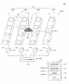
図1は、実施の形態の給電装置100を示す図である。給電装置100は、アレイアンテナ110、フェーズシフタ120、マイクロ波発生源130、カメラ140、及び制御装置150を含む。
FIG. 1 is a diagram showing a
以下では、XYZ座標系を用いて説明する。平面視とはXY平面視のことである。また、X軸は第1軸の一例であり、Y軸は第2軸の一例であり、Z軸は第3軸の一例である。また、XY平面は第1平面の一例であり、XZ平面は第2平面の一例である。 In the following, it will be described using the XYZ coordinate system. The plane view is an XY plane view. Further, the X-axis is an example of the first axis, the Y-axis is an example of the second axis, and the Z-axis is an example of the third axis. The XY plane is an example of the first plane, and the XZ plane is an example of the second plane.
アレイアンテナ110は、一例として4つのサブアレイ110A、110B、110C、110Dにグループ分けされている。サブアレイ110A~110Dは、X軸方向に配列されており、各サブアレイ110A~110Dは、一例として4つのアンテナ素子111を含む。このため、アレイアンテナ110は、一例として16個のアンテナ素子111を含む。アンテナ素子111は、平面視で矩形状のパッチアンテナである。アレイアンテナ110は、アンテナ素子111の-Z方向側にグランド電位に保持されるグランド板を有していてもよい。なお、一例として、16個のアンテナ素子111の位置の中心は、XYZ座標系の原点と一致している。
The
フェーズシフタ120は、4つのサブアレイ110A~110Dに対応して4つ設けられており、4つのフェーズシフタ120は、それぞれサブアレイ110A~110Dのアンテナ素子111に接続されている。各サブアレイ110A~110Dの中では、4つのアンテナ素子111は、1つのフェーズシフタ120に並列に接続されている。フェーズシフタ120は、位相調節部の一例である。
Four
各サブアレイ110A~110Dの中では、4つのアンテナ素子111には同一の位相の電力が供給される。また、4つのフェーズシフタ120がサブアレイ110A~110Dに出力する電力の位相は互いに異なる。このため、16個のアンテナ素子111から放射される電波が形成するビームの角度(仰角)をXZ平面内で制御することができる。また、ビームは、挟角の指向性を有し、指向性は、一例として、約5度から約15度である。
Within each of the
16個のアンテナ素子111から放射される電波が形成するビームは、アレイアンテナ110が出力するビームと同義である。また、アレイアンテナ110が出力するビームは、給電装置100が出力するビームと同義である。
The beam formed by the radio waves radiated from the 16
マイクロ波発生源130は、4つのフェーズシフタ120に接続されており、所定の電力のマイクロ波を供給する。マイクロ波発生源130は、電波発生源の一例である。マイクロ波の周波数は、一例として915MHzである。なお、ここでは給電装置100がマイクロ波発生源130を含む形態について説明するが、マイクロ波に限られるものではなく、所定の周波数の電波であればよい。
The
カメラ140は、サブアレイ110Bと110Cの間に配置される。カメラ140は、魚眼レンズ141及びカメラ本体142を有する。カメラ140は、画像取得部の一例である。
The
魚眼レンズ141は、等距離射影方式を採用したレンズである。魚眼レンズ141の中心の位置は、一例として、16個のアンテナ素子111の中心及びXYZ座標系の原点と一致している。カメラ本体142は、カメラ140のうち魚眼レンズ141以外の部分であり、所定の波長の赤外線を受光できるカメラであればよい。所定の波長は、一例として、850nmであるが、850nm以外の波長であってもよい。
The
850nmの赤外線を受光可能なカメラ140は、例えば、850nmの波長を透過するフィルタを備えた赤外線カメラ、又は、赤外線を受光可能で850nmの波長を透過するフィルタを備えたCMOS(Complementary Metal Oxide Semiconductor)イメージセンサ等である。
The
カメラ140は、魚眼レンズ141を通じてマーカを含む画像を取得し、画像データを制御装置150に出力する。マーカは、給電装置100が出力するビームを照射したいターゲットに取り付けられている。給電装置100は、カメラ140で取得した画像に含まれるマーカの位置を求め、ターゲットに向けてビームを照射する。
The
制御装置150は、位置変換部151、仰角取得部152、制御部153、及びメモリ154を有する。制御装置150は、CPU(Central Processing Unit)及びメモリを含むコンピュータによって実現される。位置変換部151、仰角取得部152、制御部153は、制御装置150が実行するプログラムの機能(ファンクション)を機能ブロックとして示したものである。また、メモリ154は、制御装置150のメモリを機能的に表したものである。
The
ここで、位置変換部151、仰角取得部152、制御部153、メモリ154については、図1に加えて図2を用いて説明する。図2は、アレイアンテナ110の極座標系を示す図である。図2には、給電装置100のうちのアレイアンテナ110とカメラ140のみを示す。また、図2には、XY平面に平行な平面上における極座標系を示す。
Here, the
また、XYZ座標系におけるマーカの位置をP1とし、原点Oと位置P1を結ぶ線分の仰角をθ、方位角をφとする。仰角は+Z方向に対する角度であり、方位角は+X方向に対する角度であり、平面視で反時計回りを正の値とする。また、位置P1をXZ平面に投影した位置P1aと原点Oとを結ぶ線分の仰角をθaとする。 Further, the position of the marker in the XYZ coordinate system is P1, the elevation angle of the line segment connecting the origin O and the position P1 is θ, and the azimuth angle is φ. The elevation angle is an angle with respect to the + Z direction, the azimuth is an angle with respect to the + X direction, and counterclockwise is a positive value in a plan view. Further, the elevation angle of the line segment connecting the position P1a projected on the XZ plane and the origin O is defined as θa.
位置P1は、第1位置の一例であり、位置P1aは、投影位置の一例である。また、原点OはXYZ座標系の基準点の一例である。 The position P1 is an example of the first position, and the position P1a is an example of the projection position. The origin O is an example of a reference point in the XYZ coordinate system.
給電装置100は、アレイアンテナ110が出力するビームの仰角をXZ平面内でのみ制御する。これは、ターゲットの位置がXZ平面からあまりずれていない(例えば、YZ平面内でのZ軸に対する仰角で±30度以内程度)ことを想定している。このような位置にあるターゲットであれば、ビームの仰角をXZ平面内で制御するだけで、ターゲットにビームを照射できるからである。
The
位置変換部151は、カメラ140が取得した画像に対して画像処理を行い、魚眼レンズ141を通じて得た等距離射影の画像をXY平面に平行な平面上における極座標に変換する。この画像処理により、カメラ140によって取得される画像に含まれるマーカのアレイアンテナ110に対する位置P1は、XY平面上の極座標における位置P2に変換される。位置P2は、第2位置の一例である。
The
位置P2は、原点Oからの動径rと偏角φによって表される。動径rは、魚眼レンズ141の焦点距離をfLとすると、r=fLθで表される。偏角φは方位角φと同一である。位置変換部151は、上述の画像処理によって、動径rをX軸に写像したr・cosφを求める。
The position P2 is represented by the radius r from the origin O and the declination φ. The radius r is represented by r = f L θ, where f L is the focal length of the
仰角取得部152は、位置P2をX軸に写像した写像位置P2aのX座標(r・cosφ)を魚眼レンズ141の焦点距離fLで除算した値(r・cosφ/fL)を、仰角θaとして取得(計算)する。このようにして仰角θaを取得できる理由については後述する。
The elevation
制御部153は、アレイアンテナ110が放射するビームの方向がXZ平面内で仰角θaになるようにフェーズシフタ120を制御する。仰角θaは、仰角取得部152によって取得される。また、制御部153は、マイクロ波発生源130の出力制御、及び、カメラ140の撮影制御等を行う。
The
メモリ154は、位置変換部151、仰角取得部152、制御部153が処理を行う際に実行するプログラム、プログラムの実行に伴い利用するデータ、プログラムの実行によって生じるデータ、及び、カメラ140が取得する画像データ等を格納する。
The
次に、仰角θaを求める方法について説明する。 Next, a method for obtaining the elevation angle θa will be described.
仰角θaは、方位角φと仰角θを用いると、位置P1と位置P1aの幾何学的関係から次式(1)で求めることができる。 The elevation angle θa can be obtained by the following equation (1) from the geometrical relationship between the position P1 and the position P1a by using the azimuth angle φ and the elevation angle θ.


また、上述したように、魚眼レンズ141の焦点距離をfLとすると、動径rは次式(4)で表される。
r=fLθ (4)
式(3)、(4)より、仰角θaは次式(5)で表すことができる。
θa=r・cosφ/fL (5)
このように、式(5)を用いて、仰角θaを近似的に求めることができる。
Further, as described above, assuming that the focal length of the
r = f L θ (4)
From the equations (3) and (4), the elevation angle θa can be expressed by the following equation (5).
θa = r · cos φ / f L (5)
In this way, the elevation angle θa can be approximately obtained by using the equation (5).
以上のように、アレイアンテナ110のビームの仰角をXZ平面内でのみ制御する場合には、等距離射影によって得られた位置P1をXY平面に平行な平面上における極座標に変換して位置P2を求め、さらに位置P2をX軸に写像した写像位置P2aのX座標(r・cosφ)を魚眼レンズ141の焦点距離fLで除算することで、仰角θa(=r・cosφ/fL)を求めることができる。
As described above, when the elevation angle of the beam of the
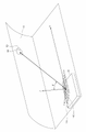
図3は、給電装置100の適用例を示す図である。給電装置100は、一例として車両30に搭載されており、トンネルの内壁10にはターゲットとしてのアンテナ20が設けられている。アンテナ20にはマーカ50が接続されている。マーカ50は、再帰反射(再帰性反射)で赤外線を反射する反射体を含む。ここで、車両30は、第1物体の一例であり、トンネルの内壁10は、第2物体の一例である。車両30が+X方向に進行すると、車両30とトンネルの内壁10とは相対的に移動するため、車両30とマーカ50も相対的に移動することになる。車両30に搭載された給電装置100に対するマーカ50の相対移動方向は、-X方向である。ここでは、車両30がマーカ50を相対的に追い越すように移動する形態について説明する。ここでは、マーカ50が停止している場合について説明するが、追い越すとは、相手が停止している場合、又は、同一方向に進行している場合に、相手を後ろから抜いて先に行くことである。
FIG. 3 is a diagram showing an application example of the
車両30が+X方向に走行する際に、カメラ140でマーカ50の位置をXY平面に平行な平面上における極座標に変換し、さらにX軸に写像した写像位置(P2aに相当する写像位置)のX座標(r・cosφ)を魚眼レンズ141の焦点距離fLで除算して求まる仰角θa(=r・cosφ/fL)を用いて、アンテナ20にビームを照射することができる。
When the
例えば、トンネルの内壁10に取り付けてあるジェットファンや標識等のインフラ構造物を内壁10に固定する固定部に、アンテナ20と、固定部のボルト等の緩みを監視するセンサと、レクテナと、キャパシタと、無線通信モジュールとを設けておき、車両30で走行しながら給電装置100からアンテナ20にビームを放射すると、アンテナ20に接続されたレクテナがマイクロ波を電力に変換する。レクテナによって変換された電力は、キャパシタに蓄積され、マーカとセンサおよび無線通信モジュールを起動する。そして、マーカが所定の動作を行い、無線通信モジュールがセンサの出力を表す信号を送信し、車両30側で受信することにより、走行しながらインフラ構造物の固定状態を検査することができる。なお、固定部のボルト等の緩みを監視するセンサは、一例として、ワッシャに組み込まれてボルトとともに締結され、ボルトの緩みを検出する。なお、マーカの所定の動作については後述する。
For example, an
また、XZ平面からずれたアンテナ20の位置からX軸に写像した写像位置(P2aに相当する写像位置)のX座標(r・cosφ)を求め、X座標(r・cosφ)を魚眼レンズ141の焦点距離fLで除算した値(r・cosφ/fL)を仰角θaとして使用してビームを制御するので、X軸方向に走行する車両30がY軸のプラスマイナスのどちらかにシフトとしている場合でも、その位置ずれを吸収して仰角θaを求めることができる。
Further, the X coordinate (r · cosφ) of the mapping position (the mapping position corresponding to P2a) mapped to the X axis from the position of the
ここで、図4を用いてマーカ50の詳細について説明する。図4は、マーカ50を示す図である。マーカ50は、筐体51、反射体52、LED53(53A~53G)、及び制御部54を含む。筐体51は、円筒状のケースである。筐体51の外周面には、2つの反射体52と、複数のLED53(53A~53G)が露出している。また、筐体51の内部には、制御部54が設けられている。
Here, the details of the
このようなマーカ50は、一例として、トンネルの内壁10(図3参照)の予め決められた位置に取り付けられる。予め決められた位置とは、一例として、トンネルを進行方向に垂直な平面で切断して得る断面における所定の位置であり、進行方向を向いて内壁10の左側の所定の高さの位置である。トンネルに沿ってこのような位置に一定間隔でマーカ50を取り付ければ、車両30でトンネルを走行する場合に、車両30の進行方向における左斜め上前方に繰り返しマーカ50が出現することになる。
As an example, such a
反射体52は、再帰反射(再帰性反射)で赤外線を反射する反射体であり、筐体51の外周面の上側と下側に設けられている。反射体52は、入射する赤外線を入射方向に沿って反射する再帰反射体(再帰性反射体)であり、例えば、フィルム状、又は、反射板型のものを用いることができる。反射体52が反射する方向は、赤外線の入射方向に略等しい。
The
LED53(53A~53G)は、筐体51の外周面で、上側の反射体52と下側の反射体52との間で周方向に沿って複数設けられており、波長が850nmの赤外線を出力する赤外線LEDである。LED53は、第2赤外線出力部の一例であり、LED53(53A~53G)が出力する赤外線は、第2赤外線の一例である。
A plurality of LEDs 53 (53A to 53G) are provided along the circumferential direction between the
マーカ50は、一例として、トンネルの内壁10(図3参照)に取り付けるので、複数のLED53(53A~53G)は、一例として、トンネルの内壁10側に位置しない半周の部分(図4で見える部分)にわたって設けられていればよい。すなわち、複数のLED53は、図4に示すように、手前側の半周分の外周面に設けられており、一例として、7つのLED53A~53Gを示す。以下では、LED53A~53Gを特に区別しない場合には、単にLED53と称す。
Since the
LED53は、赤外線を挟角で出力する指向性を有する。LED53の指向性は、一例として、約10度から約20度である。各LED53の点灯は、制御部54によって制御される。LED53A~53Gは、向かって一番左側に位置するLED53Aから、向かって一番右側に位置するLED53Gの順に配列されている。
The
制御部54は、アンテナ20で受電され、キャパシタに蓄積される電力で起動し、キャパシタに蓄積された電力を利用してLED53A~53Gを1つずつ順番に点灯させる。点灯させる順番は、LED53A~53Gの順である。これは、車両30がマーカ50に近づいてくるときに、LED53Aから順番に点灯させることによって、各LED53が出力する赤外線が車両30に搭載された給電装置100のカメラ140に照射されるようにするためである。
The
なお、LED53毎にその指向性の方向にレクテナを具備することによって、マイクロ波が照射されているレクテナに接続されているLED53が点灯するようにしてもよい。車両30の移動に伴い、車両30とマーカ50の相対的な角度変位に応じて最適な位置にあるLED56が順次点灯していくため、LED53の指向性の方向の設定について特段の制御を行う必要はないことから設計の簡易化が図れる。
By equipping each
次に、給電装置100を含む給電システム200について説明する。図5は、給電システム200における動作例を示す図である。図5では、給電システム200とマーカ50との位置関係を車両30の移動方向における右側から見た状態を示す。このため、図5では、右方向が+X方向である。また、マーカ50(A)、50(B)は、それぞれ、車両30に対する相対的な位置(A)、(B)におけるマーカ50を示す。マーカ50の相対移動方向は、-X方向である。
Next, the
給電システム200は、給電装置100と、マーカ50とを含む。マーカ50は、トンネルの内壁10に固定されており、給電装置100は、車両30に搭載されている。給電装置100は、図1及び図2に示す構成要素に加えて、さらに赤外線出力部160を含む。
The
赤外線出力部160は、一例として、波長が850nmの赤外線を出力する赤外線投光器である。赤外線出力部160は、アレイアンテナ110の近傍に設けられており、一例として、約10度から約20度の指向性を有する。赤外線出力部160の指向性は、第1指向性の一例であり、赤外線出力部160は、照射範囲160Aに赤外線を照射する。照射範囲160Aは、赤外線出力部160の指向性によって得られるものであり、車両30の進行に伴って、トンネル内でマーカ50が出現する左斜め上前方を向いている。照射範囲160Aが向く方向は、車両30がトンネル内を進行した場合に、マーカ50が出現する方向である。
The
また、図5には、アレイアンテナ110から出力されるビーム115A(115A1、115A2)を示す。ビーム115A(115A1、115A2)の指向性は、約5度から約15度である。アレイアンテナ110のビーム115Aは、ビーム115A1として示す位置や、ビーム115A2として示す方向に向けることができる。
Further, FIG. 5 shows the
図5に示すように、赤外線出力部160が照射範囲160Aに赤外線を照射しながら車両30が進行し、照射範囲160Aに位置(A)のマーカ50が入ると、マーカ50の反射体52が再帰反射によって赤外線を入射方向に反射する。
As shown in FIG. 5, the
給電装置100は、カメラ140で反射光を受光し、位置変換部151が画像処理や極座標への変換を行い、仰角取得部152が位置(A)に相当する仰角θaを取得し、制御部153がフェーズシフタ120を制御して、アレイアンテナ110が仰角θaの方向にビームを出力する。これにより、位置(A)のマーカ50にビーム115A1が出力され、マーカ50の近傍のアンテナ20が電力を受電する。
In the
車両30は進行しており、車両30に対するマーカ50の位置は、位置(A)から位置(B)に相対的に移動している。マーカ50は、車両30との相対的な位置(B)において、LED53Aから赤外線を出力する。LED53Aは、車両30が予め決められた速度でトンネル内を走行する場合に、位置(A)でアンテナ20が受電してから、位置(B)でLED53Aが赤外線を出力した場合に、車両30がLED53Aから赤外線を受光できる方向に赤外線を出力する指向性を有する。
The
給電装置100のカメラ140が位置(B)においてLED53Aから出力された赤外線を受光すると、位置変換部151が画像処理や極座標への変換を行い、仰角取得部152が位置(B)に相当する仰角θaを取得し、制御部153がフェーズシフタ120を制御して、アレイアンテナ110が仰角θaの方向にビームを出力する。これにより、位置(B)のマーカ50にビーム115A2が出力され、マーカ50の近傍のアンテナ20が電力を受電する。
When the
その後は、車両30がさらに進行し、アンテナ20が受電する度に、キャパシタに蓄積された電力を利用して、マーカ50はLED53B~53Gに赤外線を順次出力させる。給電装置100がLED53B~53Gからの赤外線を受光すると、給電装置100は、マーカ50の位置を特定し、マーカ50に向けてビーム115Aを出力する。
After that, each time the
LED53Bの指向性の向きは、LED53Aの指向性の向きに対して、給電装置100から見た位置(A)と位置(B)との間の角度の分だけずらされており、同様に、LED53C~53Gの指向性の向きは、LED53Bの指向性の向きに対して、位置(A)と位置(B)との間の角度の分だけ順次ずらされている。
The directivity direction of the
また、LED53A~53Gの挟角の指向性は、マーカ50に対して車両30が位置する距離の範囲内で、LED53A~53Gの各々の赤外線の照射範囲が重ならない程度に狭くなるように設定されている。
Further, the directivity of the sandwich angle of the
このような給電装置100によるビーム115Aの出力と、マーカ50によるLED53からの赤外線の出力とは、給電装置100がLED53Gからの赤外線を受光したことに対してビーム115Aを出力し、給電装置100がLED53からの赤外線を受光しなくなるまで行われる。
The output of the
図6は、給電装置100の制御部153が実行する処理を示す図である。図6に示す処理は、実施の形態の給電方法の処理を示す。
FIG. 6 is a diagram showing a process executed by the
制御部153は、処理がスタートすると、赤外線出力部160から赤外線を出力する(ステップS1)。
When the process starts, the
制御部153は、マーカ50から赤外線を受光したかどうかを判定する(ステップS2)。給電装置100がマーカ50から受光する赤外線は、最初(1回目)は赤外線出力部160から出力された赤外線の反射光であり、2回目以降は、マーカ50のLED53が出力した赤外線である。
The
制御部153は、赤外線を受光した(S2:YES)と判定すると、アレイアンテナ110にビーム115Aを出力させる(ステップS3)。より具体的には、位置変換部151が画像処理や極座標への変換を行い、仰角取得部152が位置(B)に相当する仰角θaを取得し、制御部153がフェーズシフタ120を制御して、アレイアンテナ110が仰角θaの方向にビームを出力する。
When the
ステップS3の処理が終了すると、制御部153はフローをステップS2にリターンさせる。
When the process of step S3 is completed, the
制御部153は、ステップS2において、赤外線を受光していない(S2:NO)と判定すると、一連の処理を終了する(エンド)。処理が終了するのは、例えば、給電装置100がLED53Gからの赤外線を受光したことに対してビーム115Aを出力し、給電装置100がLED53からの赤外線を受光しなかった場合と、マーカ50以外の物体で反射された赤外線を受光した場合である。
When the
図7は、マーカ50以外の物体60で反射された赤外線を給電装置100が受光する場合の動作を示す図である。図6において、物体60(A)、60(B)は、それぞれ、車両30に対する相対的な位置(A)、(B)における物体60を示す。
FIG. 7 is a diagram showing an operation when the
図7に示すように、赤外線出力部160が照射範囲160Aに赤外線を照射しながら車両30が進行し、照射範囲160Aに位置(A)の物体60が入り、物体60で反射された赤外線がカメラ140によって受光されたとする。物体60は、マーカ50以外の物体であり、位置(A)において車両30の方を向いていた物体や、トンネルの内壁10に設けられた再帰反射体である。
As shown in FIG. 7, the
給電装置100は、カメラ140で反射光を受光し、位置変換部151が画像処理や極座標への変換を行い、仰角取得部152が位置(A)に相当する仰角θaを取得し、制御部153がフェーズシフタ120を制御して、アレイアンテナ110が仰角θaの方向にビームを出力する。これにより、位置(A)の物体60に向けてビーム115A1が出力される。
In the
車両30は進行しており、車両30に対するマーカ50の位置は、位置(A)から位置(B)に相対的に移動している。
The
しかしながら、物体60は、アンテナ20のように受電可能な構成要素には接続されておらず、アンテナ20のように受電可能な構成要素を含まず、LED53を有していないため、給電装置100が位置(B)の物体60から赤外線を受信することはない。
However, since the
この結果、給電装置100は処理を終了する。これは、図6に示すフローチャートにおいて、ステップS1で赤外線を照射、ステップS2でYES、ステップS3でビーム115Aを出力、リターンしたステップS2でNOと判定して処理が終了するパターンである。
As a result, the
このため、給電装置100がマーカ50以外の物体60から偶然的に赤外線の反射光を受光した場合には、ビーム115Aを一度出力するだけで処理が終了することになる。この結果、無駄にビーム115Aを出力することが抑制される。
Therefore, when the
図8は、給電システム200における他の動作例を示す図である。マーカ50(A)、50(B)、50(C)は、それぞれ、車両30に対する相対的な位置(A)、(B)、(C)におけるマーカ50を示す。
FIG. 8 is a diagram showing another operation example in the
図8において、位置(A)から位置(B)までは、図5に示す動作と同一である。図8では、位置(B)よりも後の位置(C)における動作が図5とは異なる。 In FIG. 8, the operation from the position (A) to the position (B) is the same as the operation shown in FIG. In FIG. 8, the operation at the position (C) after the position (B) is different from that of FIG.
給電装置100が位置(B)のマーカ50にビーム115A2を出力し、マーカ50の近傍のアンテナ20が電力を受電する。
The
このときに、マーカ50の制御部54が、アンテナ20で受電され、キャパシタに蓄積された電力が所定量以上になったと判定すると、制御部54は、LED53Bの点灯を行わずに、LED53の点灯処理を終了する。
At this time, when the
例えば、固定部のボルト等の緩みを監視するセンサが検出を行い、検出データを無線通信モジュールが送信するのに十分な電力があると制御部54が判定した場合には、それ以上電力を受電しなくてもよいため、LED53の点灯制御を終了する。LED53の点灯制御を終了すれば、給電装置100は、ビーム115Aを出力しなくなる。
For example, if a sensor that monitors looseness of bolts or the like in the fixed portion detects it and the
この結果、位置(C)では、マーカ50は、LED53の点灯を行わない。このため、マーカ50が位置(C)にあるときには、給電装置100は、ビーム115Aを出力しない。
As a result, at the position (C), the
このように、マーカ50の制御部54が、アンテナ20によって受電され、キャパシタに蓄積された電力が所定量以上になった場合にLED53の点灯処理を終了するようにすれば、必要以上にビーム115Aや赤外線の出力を行わずに済む。
In this way, if the
図9は、マーカ50の制御部54が実行する処理を示すフローチャートである。
FIG. 9 is a flowchart showing a process executed by the
制御部54は、処理がスタートすると、キャパシタからの電力供給があるかどうかを判定する(ステップS11)。
When the process starts, the
制御部54は、電力供給がある(S11:YES)と判定すると、LED53を点灯する(ステップS12)。図9に示すフローが繰り返し実行される度に、ステップS12では、LED53A~53Gが、1つずつ順番に点灯される。
When the
制御部54は、キャパシタに蓄積されている電力が所定量以上であるかどうかを判定する(ステップS13)。
The
制御部54は、電力が所定量以上である(S13:YES)と判定すると、LED53の点灯を終了する(ステップS14)。
When the
制御部54は、ステップS14の処理を終えると、一連の処理を終了する(エンド)。
When the
また、制御部54は、ステップS13において、電力が所定量以上ではない(S13:NO)と判定すると、フローをステップS11にリターンする。
Further, when the
また、制御部54は、ステップS11において、電力供給がない(S11:YES)と判定した場合にも、一連の処理を終了する(エンド)。
Further, the
制御部54が図9に示すような処理を行うことにより、図8に示すように、位置(C)では、マーカ50はLED53を点灯しなくなる制御が行われ、給電装置100はビーム115Aを出力しなくなる。これは、図9において、マーカ50が位置(A)及び(B)にいるときに、ステップS11でYES、ステップS12、ステップS13でNOでステップS11にリターンする処理が行われた後に、マーカ50が位置(C)に相対的に移動すると、ステップS13でYESと判定し、ステップS14でLED53を点灯しなくなることに相当する。
By performing the processing as shown in FIG. 9 by the
以上のように、給電装置100は、赤外線(反射光又はLED53の赤外線)を受光すると、赤外線の到来方向に向けてビーム115Aを出力する。赤外線がマーカ50から到来した場合には、給電装置100は、再び赤外線を受信することになり、赤外線を受信する度にビーム115Aを出力することになる。この結果、無線通信モジュールがセンサの出力を表す信号を放射し、車両30側で受信することにより、走行しながらインフラ構造物の固定状態を検査することができる。また、赤外線がマーカ50以外の物体60から到来した場合には、物体60はビーム115Aを受電しないので、そこで処理を終える。
As described above, when the
このように、給電装置100が二回目以降にビーム115Aを出力するかどうかは、最初に赤外線出力部160が出力した赤外線を反射する物体が、マーカ50であるかマーカ50以外の物体60であるかによって決まり、マーカ50であるかどうかを特に識別しているわけではない。
As described above, whether or not the
このため、非常に簡単な構成でマーカ50に対してビーム115Aを出力して給電を行うことができる。
Therefore, the
したがって、簡易な構成で無線給電を可能とする給電システム200、給電装置100、及び、給電方法を提供することができる。
Therefore, it is possible to provide a
また、挟角の指向性を有するLED53(53A~53G)を含むマーカ50を用いることにより、反射源がマーカ50であるかどうかを識別することなく、マーカ50にのみ継続的に給電を行うことが可能になっている。
Further, by using the
また、マーカ50は、電源を持たずに、アンテナ20がビームを受信することによってキャパシタに蓄えられた電力で駆動するパッシブタイプであるため、電力を供給するためのケーブルやバッテリ等が不要であり、ランニングコストが低く、メインテナンス性に優れている。
Further, since the
また、マーカ50は、再帰反射(再帰性反射)で赤外線を反射する反射体52を有するので、給電装置100の赤外線出力部160に向けて赤外線を反射できる。そして、給電装置100は、赤外線の反射源であるマーカ50が存在する方向を表す仰角θaの方向にビーム115Aを出力し、マーカ50の近傍に配置されたアンテナ2がビーム115Aを受電する。このため、相対的に移動するマーカ50に確実に電力を供給することができ、信頼性の高い給電システム200を提供できる。
Further, since the
また、給電装置100は、アレイアンテナ110が出力するビームの仰角をXZ平面内でのみ制御するため、仰角をXZ平面内とYZ平面内の両方で制御する場合に比べてフェーズシフタ120の数が4分の1で済む。このため、給電装置100を安価に実現することができる。
Further, since the
なお、以上では、給電装置100からアンテナ20を介してマーカ50に電力が供給される度に、マーカ50がLED53A~53Gを点灯させる形態について説明した。1つのアンテナ20から複数のセンサに電力が供給されて、各センサが検出した検出データを順番に無線通信モジュールが送信する場合に、1回の出力によるビーム115Aがどの程度の電力量を有するかは、センサの数、1回の出力によるビーム115Aで動作するセンサの数、キャパシタの容量等に応じて決定すればよい。
In the above, the form in which the
また、以上では、車両30がマーカ50を相対的に追い越すように移動する形態について説明したが、車両30とマーカ50がすれ違うように移動する形態であってもよい。すれ違うとは、車両30とマーカ50が互いに反対方向に移動しているときに、入れ違いになることである。
Further, although the mode in which the
また、以上では、魚眼レンズ141の中心が16個のアンテナ素子111の中心と一致している形態について説明した。しかしながら、魚眼レンズ141の中心は、16個のアンテナ素子111の中心からずれていてもよい。この場合には、位置ずれの分だけアレイアンテナ制御位相計算の座標原点をずらせばよい。
Further, in the above, the form in which the center of the
また、ここでは図3を用いて給電装置100がトンネルの内壁10に設けられた無線通信モジュールと通信する形態について説明したが、無線通信モジュールはトンネルの内壁10に設けられているものに限らず、様々な場所等に設置されていてよい。このようにすれば、給電装置100を通信装置として利用することができる。
Further, although the mode in which the
以上、本発明の例示的な実施の形態の給電システム、給電装置、及び、給電方法について説明したが、本発明は、具体的に開示された実施の形態に限定されるものではなく、特許請求の範囲から逸脱することなく、種々の変形や変更が可能である。 Although the power supply system, the power supply device, and the power supply method according to the exemplary embodiment of the present invention have been described above, the present invention is not limited to the specifically disclosed embodiments and claims for a patent. Various modifications and changes are possible without departing from the range of.
50 マーカ
52 反射体
53、53A~53 GLED
100 給電装置
110 アレイアンテナ
110A~110D サブアレイ
111 アンテナ素子
120 フェーズシフタ
130 マイクロ波発生源
140 カメラ
141 魚眼レンズ
150 制御装置
151 位置変換部
152 仰角取得部
153 制御部
160 赤外線出力部
50
100
Claims (7)
前記第2物体に設けられ、再帰反射で第1赤外線を反射する反射体と、
前記第2物体に設けられ、相対的に移動する前記第1物体が存在する第2方向に第2赤外線を出力する第2指向性を有し、無線給電によって受電した電力で前記第2赤外線を出力する第2赤外線出力部と、
前記第1物体に設けられ、前記第1赤外線の前記反射体による反射赤外線、又は、前記第2赤外線を受光すると、前記反射赤外線、又は、前記第2赤外線の到来方向にビームを出力する、給電部と
を含む、給電システム。 A first directivity that outputs the first infrared ray in the first direction in which the second object that is provided in the first object and moves relative to the first object appears, and outputs the first infrared ray. Infrared output unit and
A reflector provided on the second object and reflecting the first infrared ray by retroreflection,
It has a second directivity that outputs the second infrared ray in the second direction in which the first object that is provided in the second object and moves relatively exists, and the second infrared ray is emitted by the electric power received by wireless power supply. The second infrared output unit to output and
When the infrared rays reflected by the reflector of the first infrared rays or the second infrared rays are received, a beam is output in the direction of arrival of the reflected infrared rays or the second infrared rays, which is provided on the first object. Power supply system including the part.
第1軸及び第2軸に沿って二次元的に配置される複数のアンテナ素子を有するアレイアンテナと、
電波発生源と、
前記アレイアンテナと前記電波発生源との間に設けられ、前記電波発生源から前記複数のアンテナ素子に供給される電力の位相を前記第1軸方向において調節する位相調節部と、
魚眼レンズを通じて画像を取得する画像取得部と、
前記画像取得部によって取得される画像に含まれるマーカの前記画像取得部に対する第1位置を、前記第1軸及び前記第2軸を含む第1平面上の極座標における第2位置に変換する位置変換部と、
前記第2位置に基づいて、前記第1位置を前記第1軸と第3軸とを含む第2平面に投影した投影位置の前記第2平面内での前記第3軸に対する仰角を求める仰角取得部と、
前記アレイアンテナが放射するビームの方向が前記第2平面内で前記仰角になるように前記位相調節部を制御する制御部と
を有する、請求項1乃至4のいずれか一項記載の給電システム。 The feeding unit is
An array antenna having a plurality of antenna elements arranged two-dimensionally along the first axis and the second axis, and
Radio wave source and
A phase adjusting unit provided between the array antenna and the radio wave generation source and adjusting the phase of electric power supplied from the radio wave generation source to the plurality of antenna elements in the first axis direction.
An image acquisition unit that acquires images through a fisheye lens,
Position conversion that converts the first position of the marker included in the image acquired by the image acquisition unit with respect to the image acquisition unit to the second position in polar coordinates on the first plane including the first axis and the second axis. Department and
Obtaining an elevation angle for obtaining an elevation angle of a projected position in the second plane in which the first position is projected onto a second plane including the first axis and the third axis based on the second position. Department and
The power feeding system according to any one of claims 1 to 4, further comprising a control unit that controls the phase adjusting unit so that the direction of the beam emitted by the array antenna is the elevation angle in the second plane.
前記第1物体に設けられる給電部であって、前記第2物体に設けられ再帰反射で第1赤外線を反射する反射体による反射赤外線、又は、前記第2物体に設けられ相対的に移動する前記第1物体が存在する第2方向に第2赤外線を出力する第2指向性を有する第2赤外線出力部が無線給電によって受電した電力で出力した前記第2赤外線を受光すると、前記反射赤外線、又は、前記第2赤外線の到来方向にビームを出力する、給電部と
を含む、給電装置。 A first directivity that outputs the first infrared ray in the first direction in which the second object that is provided in the first object and moves relative to the first object appears, and outputs the first infrared ray. Infrared output unit and
The feeding unit provided in the first object, which is reflected infrared rays by a reflector provided in the second object and reflects the first infrared rays by retroreflection, or the infrared rays reflected in the second object and relatively moving. When the second infrared ray output unit having the second directivity that outputs the second infrared ray in the second direction in which the first object exists receives the second infrared ray output by the power received by the wireless power supply, the reflected infrared ray or the reflected infrared ray or the second infrared ray is received. A power feeding device including a feeding unit that outputs a beam in the direction of arrival of the second infrared ray.
前記第2物体に設けられ、再帰反射で第1赤外線を反射する反射体と、
前記第2物体に設けられ、相対的に移動する前記第1物体が存在する第2方向に第2赤外線を出力する第2指向性を有し、無線給電によって受電した電力で前記第2赤外線を出力する第2赤外線出力部と
を含む給電システムにおける給電方法であって、
前記第1赤外線の前記反射体による反射赤外線、又は、前記第2赤外線を前記第1物体側で受光すると、前記反射赤外線、又は、前記第2赤外線の到来方向にビームを出力する、給電方法。 A first directivity that outputs the first infrared ray in the first direction in which the second object that is provided in the first object and moves relative to the first object appears, and outputs the first infrared ray. Infrared output unit and
A reflector provided on the second object and reflecting the first infrared ray by retroreflection,
It has a second directivity that outputs the second infrared ray in the second direction in which the first object that is provided in the second object and moves relatively exists, and the second infrared ray is emitted by the electric power received by wireless power supply. It is a power supply method in a power supply system including a second infrared output unit that outputs.
A power feeding method in which when the first infrared ray reflected by the reflector or the second infrared ray is received on the first object side, a beam is output in the direction of arrival of the reflected infrared ray or the second infrared ray.
Priority Applications (5)
| Application Number | Priority Date | Filing Date | Title |
|---|---|---|---|
| JP2020031361A JP7069232B2 (en) | 2020-02-27 | 2020-02-27 | Power supply system, power supply device, and power supply method |
| CN202180016781.1A CN115136452A (en) | 2020-02-27 | 2021-01-06 | Power supply system, power supply device and power supply method |
| PCT/JP2021/000213 WO2021171790A1 (en) | 2020-02-27 | 2021-01-06 | Power supply system, power supply device, and power supply method |
| EP21761119.3A EP4084285A4 (en) | 2020-02-27 | 2021-01-06 | Power supply system, power supply device, and power supply method |
| US17/759,395 US20230088273A1 (en) | 2020-02-27 | 2021-01-06 | Power supply system, power supply device, and power supply method |
Applications Claiming Priority (1)
| Application Number | Priority Date | Filing Date | Title |
|---|---|---|---|
| JP2020031361A JP7069232B2 (en) | 2020-02-27 | 2020-02-27 | Power supply system, power supply device, and power supply method |
Publications (2)
| Publication Number | Publication Date |
|---|---|
| JP2021136778A JP2021136778A (en) | 2021-09-13 |
| JP7069232B2 true JP7069232B2 (en) | 2022-05-17 |
Family
ID=77491405
Family Applications (1)
| Application Number | Title | Priority Date | Filing Date |
|---|---|---|---|
| JP2020031361A Active JP7069232B2 (en) | 2020-02-27 | 2020-02-27 | Power supply system, power supply device, and power supply method |
Country Status (5)
| Country | Link |
|---|---|
| US (1) | US20230088273A1 (en) |
| EP (1) | EP4084285A4 (en) |
| JP (1) | JP7069232B2 (en) |
| CN (1) | CN115136452A (en) |
| WO (1) | WO2021171790A1 (en) |
Families Citing this family (2)
| Publication number | Priority date | Publication date | Assignee | Title |
|---|---|---|---|---|
| JP6795637B2 (en) * | 2019-02-20 | 2020-12-02 | ミネベアミツミ株式会社 | Antenna device and power supply device |
| JP7443440B1 (en) | 2022-09-01 | 2024-03-05 | ソフトバンク株式会社 | Wireless communication system, wireless communication method, wireless power supply system, and wireless power supply method |
Citations (4)
| Publication number | Priority date | Publication date | Assignee | Title |
|---|---|---|---|---|
| US20150311755A1 (en) | 2012-12-05 | 2015-10-29 | Eads Deutschland Gmbh | Wireless Remote Energy Supply for Unmanned Aerial Vehicles |
| US20150318897A1 (en) | 2008-09-30 | 2015-11-05 | Searete Llc | Beam power with receiver priority selection |
| WO2017134951A1 (en) | 2016-02-05 | 2017-08-10 | 株式会社東芝 | Charging device and positional deviation detection method |
| JP2019126198A (en) | 2018-01-17 | 2019-07-25 | 株式会社Nttドコモ | Power supply management server and power supply system |
Family Cites Families (3)
| Publication number | Priority date | Publication date | Assignee | Title |
|---|---|---|---|---|
| JP6024361B2 (en) * | 2012-10-09 | 2016-11-16 | 日産自動車株式会社 | Non-contact power feeding device |
| JP2018121489A (en) | 2017-01-27 | 2018-08-02 | トヨタ自動車株式会社 | Non-contact power transmission system |
| JP2020031361A (en) | 2018-08-23 | 2020-02-27 | 株式会社Subaru | Vehicle relay device |
-
2020
- 2020-02-27 JP JP2020031361A patent/JP7069232B2/en active Active
-
2021
- 2021-01-06 EP EP21761119.3A patent/EP4084285A4/en active Pending
- 2021-01-06 US US17/759,395 patent/US20230088273A1/en active Pending
- 2021-01-06 CN CN202180016781.1A patent/CN115136452A/en active Pending
- 2021-01-06 WO PCT/JP2021/000213 patent/WO2021171790A1/en unknown
Patent Citations (4)
| Publication number | Priority date | Publication date | Assignee | Title |
|---|---|---|---|---|
| US20150318897A1 (en) | 2008-09-30 | 2015-11-05 | Searete Llc | Beam power with receiver priority selection |
| US20150311755A1 (en) | 2012-12-05 | 2015-10-29 | Eads Deutschland Gmbh | Wireless Remote Energy Supply for Unmanned Aerial Vehicles |
| WO2017134951A1 (en) | 2016-02-05 | 2017-08-10 | 株式会社東芝 | Charging device and positional deviation detection method |
| JP2019126198A (en) | 2018-01-17 | 2019-07-25 | 株式会社Nttドコモ | Power supply management server and power supply system |
Also Published As
| Publication number | Publication date |
|---|---|
| JP2021136778A (en) | 2021-09-13 |
| WO2021171790A1 (en) | 2021-09-02 |
| EP4084285A4 (en) | 2023-04-05 |
| EP4084285A1 (en) | 2022-11-02 |
| CN115136452A (en) | 2022-09-30 |
| US20230088273A1 (en) | 2023-03-23 |
Similar Documents
| Publication | Publication Date | Title |
|---|---|---|
| JP6795637B2 (en) | Antenna device and power supply device | |
| WO2021171790A1 (en) | Power supply system, power supply device, and power supply method | |
| US7498970B2 (en) | Monitor | |
| US20150123838A1 (en) | Radar antenna assembly | |
| WO2022054586A1 (en) | Antenna device, power supply device, and power supply method | |
| US20220413151A1 (en) | Non-line-of-sight correction for target detection and identification in point clouds | |
| JP6317657B2 (en) | Radar sensor module | |
| TW202024664A (en) | Multi-beam co-frequency microwave detecting antenna, manufacturing method and detecting method thereof | |
| KR20170114242A (en) | Scanning lidar device having extended horizential view | |
| JP2009103482A (en) | Vehicle-mounted radar device | |
| JP3101703B2 (en) | Spatial positioning system | |
| US20200191922A1 (en) | Measurement device | |
| JP3822417B2 (en) | Vehicle periphery monitoring device | |
| WO2023013160A1 (en) | Distance estimation device, antena device, power feeding system, power feeding device, and power feeding method | |
| WO2022264613A1 (en) | Antena device, feeding system, feeding apparatus, and feeding method | |
| WO2023013171A1 (en) | Distance estimation device, antena device, power feeding system, power feeding apparatus, and power feeding method | |
| KR101773176B1 (en) | Antenna for seeker and method for detecting target using the same | |
| JP7445628B2 (en) | Location information derivation system | |
| WO2021005921A1 (en) | Stereo camera and light unit with integrated stereo camera | |
| KR20180080974A (en) | Laser transmit and receiving module and integrated apparatus including the same | |
| JP2023183133A (en) | Antenna device, power supply device and power supply method | |
| JPH054061U (en) | Transceiver | |
| CN115825987A (en) | Laser radar, detection device and vehicle |
Legal Events
| Date | Code | Title | Description |
|---|---|---|---|
| A621 | Written request for application examination |
Free format text: JAPANESE INTERMEDIATE CODE: A621 Effective date: 20210617 |
|
| TRDD | Decision of grant or rejection written | ||
| A01 | Written decision to grant a patent or to grant a registration (utility model) |
Free format text: JAPANESE INTERMEDIATE CODE: A01 Effective date: 20220405 |
|
| A61 | First payment of annual fees (during grant procedure) |
Free format text: JAPANESE INTERMEDIATE CODE: A61 Effective date: 20220502 |
|
| R150 | Certificate of patent or registration of utility model |
Ref document number: 7069232 Country of ref document: JP Free format text: JAPANESE INTERMEDIATE CODE: R150 |