EP3412480A1 - Ball joint and manufacturing method therefor - Google Patents
Ball joint and manufacturing method therefor Download PDFInfo
- Publication number
- EP3412480A1 EP3412480A1 EP17747788.2A EP17747788A EP3412480A1 EP 3412480 A1 EP3412480 A1 EP 3412480A1 EP 17747788 A EP17747788 A EP 17747788A EP 3412480 A1 EP3412480 A1 EP 3412480A1
- Authority
- EP
- European Patent Office
- Prior art keywords
- ball joint
- case
- bush
- ball
- mounting
- Prior art date
- Legal status (The legal status is an assumption and is not a legal conclusion. Google has not performed a legal analysis and makes no representation as to the accuracy of the status listed.)
- Withdrawn
Links
Images


Classifications
-
- B—PERFORMING OPERATIONS; TRANSPORTING
- B60—VEHICLES IN GENERAL
- B60G—VEHICLE SUSPENSION ARRANGEMENTS
- B60G7/00—Pivoted suspension arms; Accessories thereof
- B60G7/005—Ball joints
-
- B—PERFORMING OPERATIONS; TRANSPORTING
- B29—WORKING OF PLASTICS; WORKING OF SUBSTANCES IN A PLASTIC STATE IN GENERAL
- B29C—SHAPING OR JOINING OF PLASTICS; SHAPING OF MATERIAL IN A PLASTIC STATE, NOT OTHERWISE PROVIDED FOR; AFTER-TREATMENT OF THE SHAPED PRODUCTS, e.g. REPAIRING
- B29C43/00—Compression moulding, i.e. applying external pressure to flow the moulding material; Apparatus therefor
- B29C43/003—Compression moulding, i.e. applying external pressure to flow the moulding material; Apparatus therefor characterised by the choice of material
-
- B—PERFORMING OPERATIONS; TRANSPORTING
- B29—WORKING OF PLASTICS; WORKING OF SUBSTANCES IN A PLASTIC STATE IN GENERAL
- B29C—SHAPING OR JOINING OF PLASTICS; SHAPING OF MATERIAL IN A PLASTIC STATE, NOT OTHERWISE PROVIDED FOR; AFTER-TREATMENT OF THE SHAPED PRODUCTS, e.g. REPAIRING
- B29C43/00—Compression moulding, i.e. applying external pressure to flow the moulding material; Apparatus therefor
- B29C43/02—Compression moulding, i.e. applying external pressure to flow the moulding material; Apparatus therefor of articles of definite length, i.e. discrete articles
- B29C43/18—Compression moulding, i.e. applying external pressure to flow the moulding material; Apparatus therefor of articles of definite length, i.e. discrete articles incorporating preformed parts or layers, e.g. compression moulding around inserts or for coating articles
-
- B—PERFORMING OPERATIONS; TRANSPORTING
- B29—WORKING OF PLASTICS; WORKING OF SUBSTANCES IN A PLASTIC STATE IN GENERAL
- B29C—SHAPING OR JOINING OF PLASTICS; SHAPING OF MATERIAL IN A PLASTIC STATE, NOT OTHERWISE PROVIDED FOR; AFTER-TREATMENT OF THE SHAPED PRODUCTS, e.g. REPAIRING
- B29C45/00—Injection moulding, i.e. forcing the required volume of moulding material through a nozzle into a closed mould; Apparatus therefor
- B29C45/14—Injection moulding, i.e. forcing the required volume of moulding material through a nozzle into a closed mould; Apparatus therefor incorporating preformed parts or layers, e.g. injection moulding around inserts or for coating articles
-
- B—PERFORMING OPERATIONS; TRANSPORTING
- B29—WORKING OF PLASTICS; WORKING OF SUBSTANCES IN A PLASTIC STATE IN GENERAL
- B29C—SHAPING OR JOINING OF PLASTICS; SHAPING OF MATERIAL IN A PLASTIC STATE, NOT OTHERWISE PROVIDED FOR; AFTER-TREATMENT OF THE SHAPED PRODUCTS, e.g. REPAIRING
- B29C70/00—Shaping composites, i.e. plastics material comprising reinforcements, fillers or preformed parts, e.g. inserts
- B29C70/04—Shaping composites, i.e. plastics material comprising reinforcements, fillers or preformed parts, e.g. inserts comprising reinforcements only, e.g. self-reinforcing plastics
- B29C70/06—Fibrous reinforcements only
- B29C70/10—Fibrous reinforcements only characterised by the structure of fibrous reinforcements, e.g. hollow fibres
- B29C70/12—Fibrous reinforcements only characterised by the structure of fibrous reinforcements, e.g. hollow fibres using fibres of short length, e.g. in the form of a mat
-
- B—PERFORMING OPERATIONS; TRANSPORTING
- B29—WORKING OF PLASTICS; WORKING OF SUBSTANCES IN A PLASTIC STATE IN GENERAL
- B29C—SHAPING OR JOINING OF PLASTICS; SHAPING OF MATERIAL IN A PLASTIC STATE, NOT OTHERWISE PROVIDED FOR; AFTER-TREATMENT OF THE SHAPED PRODUCTS, e.g. REPAIRING
- B29C70/00—Shaping composites, i.e. plastics material comprising reinforcements, fillers or preformed parts, e.g. inserts
- B29C70/04—Shaping composites, i.e. plastics material comprising reinforcements, fillers or preformed parts, e.g. inserts comprising reinforcements only, e.g. self-reinforcing plastics
- B29C70/28—Shaping operations therefor
- B29C70/40—Shaping or impregnating by compression not applied
- B29C70/42—Shaping or impregnating by compression not applied for producing articles of definite length, i.e. discrete articles
- B29C70/46—Shaping or impregnating by compression not applied for producing articles of definite length, i.e. discrete articles using matched moulds, e.g. for deforming sheet moulding compounds [SMC] or prepregs
- B29C70/465—Shaping or impregnating by compression not applied for producing articles of definite length, i.e. discrete articles using matched moulds, e.g. for deforming sheet moulding compounds [SMC] or prepregs and impregnating by melting a solid material, e.g. sheets, powders of fibres
-
- F—MECHANICAL ENGINEERING; LIGHTING; HEATING; WEAPONS; BLASTING
- F16—ENGINEERING ELEMENTS AND UNITS; GENERAL MEASURES FOR PRODUCING AND MAINTAINING EFFECTIVE FUNCTIONING OF MACHINES OR INSTALLATIONS; THERMAL INSULATION IN GENERAL
- F16C—SHAFTS; FLEXIBLE SHAFTS; ELEMENTS OR CRANKSHAFT MECHANISMS; ROTARY BODIES OTHER THAN GEARING ELEMENTS; BEARINGS
- F16C11/00—Pivots; Pivotal connections
- F16C11/04—Pivotal connections
- F16C11/06—Ball-joints; Other joints having more than one degree of angular freedom, i.e. universal joints
- F16C11/0619—Ball-joints; Other joints having more than one degree of angular freedom, i.e. universal joints the female part comprising a blind socket receiving the male part
- F16C11/0623—Construction or details of the socket member
- F16C11/0657—Construction or details of the socket member the socket member being mainly made of plastics
-
- F—MECHANICAL ENGINEERING; LIGHTING; HEATING; WEAPONS; BLASTING
- F16—ENGINEERING ELEMENTS AND UNITS; GENERAL MEASURES FOR PRODUCING AND MAINTAINING EFFECTIVE FUNCTIONING OF MACHINES OR INSTALLATIONS; THERMAL INSULATION IN GENERAL
- F16C—SHAFTS; FLEXIBLE SHAFTS; ELEMENTS OR CRANKSHAFT MECHANISMS; ROTARY BODIES OTHER THAN GEARING ELEMENTS; BEARINGS
- F16C11/00—Pivots; Pivotal connections
- F16C11/04—Pivotal connections
- F16C11/06—Ball-joints; Other joints having more than one degree of angular freedom, i.e. universal joints
- F16C11/0666—Sealing means between the socket and the inner member shaft
- F16C11/0671—Sealing means between the socket and the inner member shaft allowing operative relative movement of joint parts due to flexing of the sealing means
-
- F—MECHANICAL ENGINEERING; LIGHTING; HEATING; WEAPONS; BLASTING
- F16—ENGINEERING ELEMENTS AND UNITS; GENERAL MEASURES FOR PRODUCING AND MAINTAINING EFFECTIVE FUNCTIONING OF MACHINES OR INSTALLATIONS; THERMAL INSULATION IN GENERAL
- F16C—SHAFTS; FLEXIBLE SHAFTS; ELEMENTS OR CRANKSHAFT MECHANISMS; ROTARY BODIES OTHER THAN GEARING ELEMENTS; BEARINGS
- F16C11/00—Pivots; Pivotal connections
- F16C11/04—Pivotal connections
- F16C11/06—Ball-joints; Other joints having more than one degree of angular freedom, i.e. universal joints
- F16C11/0685—Manufacture of ball-joints and parts thereof, e.g. assembly of ball-joints
-
- F—MECHANICAL ENGINEERING; LIGHTING; HEATING; WEAPONS; BLASTING
- F16—ENGINEERING ELEMENTS AND UNITS; GENERAL MEASURES FOR PRODUCING AND MAINTAINING EFFECTIVE FUNCTIONING OF MACHINES OR INSTALLATIONS; THERMAL INSULATION IN GENERAL
- F16C—SHAFTS; FLEXIBLE SHAFTS; ELEMENTS OR CRANKSHAFT MECHANISMS; ROTARY BODIES OTHER THAN GEARING ELEMENTS; BEARINGS
- F16C11/00—Pivots; Pivotal connections
- F16C11/04—Pivotal connections
- F16C11/06—Ball-joints; Other joints having more than one degree of angular freedom, i.e. universal joints
- F16C11/0695—Mounting of ball-joints, e.g. fixing them to a connecting rod
-
- B—PERFORMING OPERATIONS; TRANSPORTING
- B29—WORKING OF PLASTICS; WORKING OF SUBSTANCES IN A PLASTIC STATE IN GENERAL
- B29K—INDEXING SCHEME ASSOCIATED WITH SUBCLASSES B29B, B29C OR B29D, RELATING TO MOULDING MATERIALS OR TO MATERIALS FOR MOULDS, REINFORCEMENTS, FILLERS OR PREFORMED PARTS, e.g. INSERTS
- B29K2063/00—Use of EP, i.e. epoxy resins or derivatives thereof, as moulding material
-
- B—PERFORMING OPERATIONS; TRANSPORTING
- B29—WORKING OF PLASTICS; WORKING OF SUBSTANCES IN A PLASTIC STATE IN GENERAL
- B29K—INDEXING SCHEME ASSOCIATED WITH SUBCLASSES B29B, B29C OR B29D, RELATING TO MOULDING MATERIALS OR TO MATERIALS FOR MOULDS, REINFORCEMENTS, FILLERS OR PREFORMED PARTS, e.g. INSERTS
- B29K2105/00—Condition, form or state of moulded material or of the material to be shaped
- B29K2105/06—Condition, form or state of moulded material or of the material to be shaped containing reinforcements, fillers or inserts
- B29K2105/12—Condition, form or state of moulded material or of the material to be shaped containing reinforcements, fillers or inserts of short lengths, e.g. chopped filaments, staple fibres or bristles
-
- B—PERFORMING OPERATIONS; TRANSPORTING
- B29—WORKING OF PLASTICS; WORKING OF SUBSTANCES IN A PLASTIC STATE IN GENERAL
- B29K—INDEXING SCHEME ASSOCIATED WITH SUBCLASSES B29B, B29C OR B29D, RELATING TO MOULDING MATERIALS OR TO MATERIALS FOR MOULDS, REINFORCEMENTS, FILLERS OR PREFORMED PARTS, e.g. INSERTS
- B29K2307/00—Use of elements other than metals as reinforcement
- B29K2307/04—Carbon
-
- B—PERFORMING OPERATIONS; TRANSPORTING
- B29—WORKING OF PLASTICS; WORKING OF SUBSTANCES IN A PLASTIC STATE IN GENERAL
- B29L—INDEXING SCHEME ASSOCIATED WITH SUBCLASS B29C, RELATING TO PARTICULAR ARTICLES
- B29L2031/00—Other particular articles
- B29L2031/30—Vehicles, e.g. ships or aircraft, or body parts thereof
- B29L2031/3002—Superstructures characterized by combining metal and plastics, i.e. hybrid parts
-
- B—PERFORMING OPERATIONS; TRANSPORTING
- B29—WORKING OF PLASTICS; WORKING OF SUBSTANCES IN A PLASTIC STATE IN GENERAL
- B29L—INDEXING SCHEME ASSOCIATED WITH SUBCLASS B29C, RELATING TO PARTICULAR ARTICLES
- B29L2031/00—Other particular articles
- B29L2031/30—Vehicles, e.g. ships or aircraft, or body parts thereof
- B29L2031/3055—Cars
-
- B—PERFORMING OPERATIONS; TRANSPORTING
- B60—VEHICLES IN GENERAL
- B60G—VEHICLE SUSPENSION ARRANGEMENTS
- B60G2204/00—Indexing codes related to suspensions per se or to auxiliary parts
- B60G2204/40—Auxiliary suspension parts; Adjustment of suspensions
-
- B—PERFORMING OPERATIONS; TRANSPORTING
- B60—VEHICLES IN GENERAL
- B60G—VEHICLE SUSPENSION ARRANGEMENTS
- B60G2204/00—Indexing codes related to suspensions per se or to auxiliary parts
- B60G2204/40—Auxiliary suspension parts; Adjustment of suspensions
- B60G2204/416—Ball or spherical joints
-
- B—PERFORMING OPERATIONS; TRANSPORTING
- B60—VEHICLES IN GENERAL
- B60G—VEHICLE SUSPENSION ARRANGEMENTS
- B60G2206/00—Indexing codes related to the manufacturing of suspensions: constructional features, the materials used, procedures or tools
- B60G2206/01—Constructional features of suspension elements, e.g. arms, dampers, springs
- B60G2206/10—Constructional features of arms
- B60G2206/122—Constructional features of arms the arm having L-shape
-
- B—PERFORMING OPERATIONS; TRANSPORTING
- B60—VEHICLES IN GENERAL
- B60G—VEHICLE SUSPENSION ARRANGEMENTS
- B60G2206/00—Indexing codes related to the manufacturing of suspensions: constructional features, the materials used, procedures or tools
- B60G2206/01—Constructional features of suspension elements, e.g. arms, dampers, springs
- B60G2206/70—Materials used in suspensions
- B60G2206/71—Light weight materials
- B60G2206/7101—Fiber-reinforced plastics [FRP]
-
- B—PERFORMING OPERATIONS; TRANSPORTING
- B60—VEHICLES IN GENERAL
- B60G—VEHICLE SUSPENSION ARRANGEMENTS
- B60G2206/00—Indexing codes related to the manufacturing of suspensions: constructional features, the materials used, procedures or tools
- B60G2206/01—Constructional features of suspension elements, e.g. arms, dampers, springs
- B60G2206/70—Materials used in suspensions
- B60G2206/72—Steel
-
- B—PERFORMING OPERATIONS; TRANSPORTING
- B60—VEHICLES IN GENERAL
- B60G—VEHICLE SUSPENSION ARRANGEMENTS
- B60G2206/00—Indexing codes related to the manufacturing of suspensions: constructional features, the materials used, procedures or tools
- B60G2206/01—Constructional features of suspension elements, e.g. arms, dampers, springs
- B60G2206/80—Manufacturing procedures
- B60G2206/81—Shaping
- B60G2206/8101—Shaping by casting
- B60G2206/81012—Shaping by casting by injection moulding
-
- B—PERFORMING OPERATIONS; TRANSPORTING
- B60—VEHICLES IN GENERAL
- B60G—VEHICLE SUSPENSION ARRANGEMENTS
- B60G2206/00—Indexing codes related to the manufacturing of suspensions: constructional features, the materials used, procedures or tools
- B60G2206/01—Constructional features of suspension elements, e.g. arms, dampers, springs
- B60G2206/80—Manufacturing procedures
- B60G2206/82—Joining
-
- F—MECHANICAL ENGINEERING; LIGHTING; HEATING; WEAPONS; BLASTING
- F16—ENGINEERING ELEMENTS AND UNITS; GENERAL MEASURES FOR PRODUCING AND MAINTAINING EFFECTIVE FUNCTIONING OF MACHINES OR INSTALLATIONS; THERMAL INSULATION IN GENERAL
- F16C—SHAFTS; FLEXIBLE SHAFTS; ELEMENTS OR CRANKSHAFT MECHANISMS; ROTARY BODIES OTHER THAN GEARING ELEMENTS; BEARINGS
- F16C2326/00—Articles relating to transporting
- F16C2326/01—Parts of vehicles in general
- F16C2326/05—Vehicle suspensions, e.g. bearings, pivots or connecting rods used therein
Definitions
- the present disclosure relates to a ball joint and a manufacturing method thereof, and more particularly, to a ball joint that is manufactured using a hot press molding method of a carbon fiber-reinforced plastic (CFRP) and a plastic injection molding method and to a manufacturing method of such a ball joint.
- CFRP carbon fiber-reinforced plastic
- a suspension of a vehicle is an apparatus for connecting a vehicle body and a wheel, and includes a spring for absorbing vibration or shock transmitted from a road surface to the vehicle body, a shock absorber for adjusting the operation of the spring, a suspension arm or link for controlling the operation of a wheel, and so on.
- a ball universal joint or a ball joint, a bush, and so on are used in order to connect the suspension to the vehicle body or the wheel such that the suspension is movable relative to the vehicle body or the wheel.
- one end of a lower control arm that supports a lateral force, a longitudinal force, and a vertical force input through the wheel during running of the vehicle is connected to a knuckle fastened in to the wheel via a ball joint in order to steer the wheel, and the other end of the lower control arm is connected to the vehicle body through a bush.
- the above-described conventional ball joint has a structure in which the ball of a ball stud is rotatably inserted into a housing, and includes a ball stud having a ball made of a rigid body, a housing or a ball joint case enclosing the ball stud, a bearing interposed between the housing and the ball of the ball stud so as to make the ball stud freely movable, a dust cover that prevents foreign matter from infiltrating into the housing, and a ball joint mounting case that accommodates the ball joint case and is mounted on a lower control arm.
- the mounting cases of such conventional ball joints, which were used, were made of a steel material.
- the mounting cases of ball joints have been manufactured through a forging method using lightweight aluminum, rather than steel.
- the present disclosure has been made in view of the above circumstances, and the present disclosure provides a ball joint and a method of manufacturing the ball joint, in which a more effective weight reduction can be achieved by higher weight saving and durability can also be enhanced.
- a ball joint may include: a ball stud including a ball; a bearing configured to enclose and support the ball of the ball stud; a case bush configured to accommodate a portion of the ball stud and the bearing; a ball joint mounting case configured to accommodate the case bush and fastened to a suspension arm, the ball joint mounting case being made of a carbon fiber-reinforced plastic (CFRP); and a case cap accommodated in the case bush.
- CFRP carbon fiber-reinforced plastic
- the ball joint may further include: a dust cover configured to cover an upper portion of the case bush and an upper portion of the ball joint mounting case; and a ring clip configured to fix the dust cover to the ball joint mounting case.
- At least one bolt mounting bush may be inserted into and integrally coupled to the ball joint mounting case.
- the suspension arm is a lower control arm
- the ball joint mounting case may be mounted on one end of the lower control arm
- the case bush may include a cylindrical bush body having a bottom face and an opening on the opposite side of the bottom face.
- a ring-shaped engagement protrusion may be formed on an upper portion of an outer face of the bush body so as to integrally protrude radially outwards.
- a circular rim may be formed on the bottom face so as to extend radially outwards.
- a corner portion protruding radially outward may be formed at a predetermined portion of the outer face between the engagement protrusion and the rim.
- the case bush may be formed of a steel material and treated with a phosphoric acid anodizing.
- the case bush may be applied with a corrosion-resistant primer.
- a seating step may be formed on an inner face of the case bush so as to protrude radially inwards such that the case cap is seated and supported on the seating step.
- the bolt mounting bush may include a cylindrical bush body having openings on opposite sides thereof.
- a rim may be integrally formed on an upper portion of an outer face of the bush body so as to extend radially outwards.
- At least one engagement protrusion may be integrally formed on the outer face of the bush body so as to extend in a height direction and protrude radially outwards.
- the bolt mounting bush may be formed of a steel material, treated with phosphoric acid anodizing, and applied with a corrosion-resistant primer.
- the ball joint mounting case may be made of CFRP through a hot press method.
- a manufacturing method of a ball joint may include: manufacturing at least one mounting bush and a case bush and integrally coupling the mounting bush and the case bush to a ball joint mounting case; manufacturing a ball stud including a ball and a bearing and coupling the bearing to the ball stud so as to enclose the ball; and manufacturing a case cap and assembling by inserting the case cap into the case bush together with the assembly of the ball stud and the bearing.
- the ball joint mounting case may be made of carbon fiber-reinforced plastic.
- the ball joint mounting case may be manufactured with the carbon fiber-reinforced plastic by a hot press method.
- a charge in which a product shape is considered may be manufactured by using carbon chips, and the ball joint mounting case may be manufactured by inserting the charge into a mold, and applying heat and pressure to the charge.
- the carbon chips may be chips cut from a prepreg (UD tape) or a tow prepreg.
- the carbon chips may be made of a mixture of carbon fibers and an epoxy resin.
- the method may further include covering the ball stud with a dust cover and then fixedly fitting a ring clip on the dust cover.
- lubricant in the coupling the bearing to the ball stud so as to enclose the ball, lubricant may be injected.
- lubricant in a step of the covering the ball stud with the dust cover and then fixedly fitting the ring clip on the dust cover, lubricant may be injected.
- the case bush is treated with swaging.
- the ball joint mounting case is made of a carbon fiber-reinforced plastic by a hot press method, and the case bush is injection molded using a plastic material.
- the case bush is injection molded using a plastic material.
- the case bush is injection molded in the state in which the ball stud and the bearing are inserted into the inside of the ball joint mounting case.
- the high strength, high durability, and impact resistance can be further improved.
- the ball joint is applied to a suspension arm such as a lower control arm of a vehicle, the steering performance and ride comfort of the vehicle can be improved.
- the ball joint can be designed and analyzed easily, and since a lamination process according to the layout pattern is not required, the manufacturing time of a component of a composite material can be remarkably shortened and the productivity can be improved.
- the bolt mounting bush made of a metal is inserted into the ball joint mounting case so as to be integrally formed, the durability can be improved more effectively, and layout can be secured easily.
- a ball joint 100 may include: a ball stud 10 made of a rigid body; a bearing 20 that encloses the ball of the ball stud 10 and supports the ball stud 10 to be freely rotatable; a case bush 30 that accommodates a portion of the ball stud 10 and the bearing 20; a ball joint mounting case 40 that accommodates the case bush 30 and is fastened to a suspension arm (not illustrated); a dust cover 50 that covers the upper portions of the case bush 30 and the ball joint mounting case 40 so as to prevent foreign matter from infiltrating into the ball joint mounting case 40; a ring clip 60 that fixes the dust cover 50 to the ball joint mounting case 40; at least one bolt mounting bush 70 inserted into and coupled to the ball joint mounting case 40; and a case cap 80 accommodated in the case bush 30.
- the ball joint mounting case 40 may be molded using a CFRP.
- the case bush 30 may be formed of a steel material.
- the ball joint 100 may be mounted on one end of a suspension arm of a vehicle, for example, one end of a lower control arm 200.
- the ball joint 100 may be mounted on one end of the lower control arm 200, a first bush 210 may be mounted on the other end of the lower control arm 200, and a second bush 220 may be mounted on a predetermined portion between the ball joint 100 and the first bush 210.
- the lower control arm 200 may be connected to a knuckle of a wheel (not illustrated) through the ball joint 100, and the first and second bushes 210 and 220 may be fastened to a vehicle body (not illustrated), so that the wheel can be supported by the vehicle body through the lower control arm 200.
- the case bush 30 inserted into the ball joint mounting case 40 and integrally coupled to the ball joint mounting case 40 includes a cylindrical bush body 34 having a bottom face 32 and an opening on the opposite side of the bottom face 32.
- a ring-shaped engagement protrusion 36 may be formed on the outer face of the bush body 34 so as to integrally protrude radially outwards, a circular rim 38 may be formed on the bottom face 32 to extend radially outwards, and a corner portion 37 protruding radially outwards from a predetermined portion of the outer face may be formed between the engagement protrusion 36 and the rim 38.
- the engagement protrusion 36, the corner portion 37, and the rim 37 prevent axial separation between the case bush 30 and the ball joint mounting case 40, thereby increasing the coupling force of the case bush 30 and the joint mounting case 40.
- case bush 30 is inserted into the ball joint mounting case 40, corrosion resistance can be improved even if the case bush 30 is formed of a steel material.
- the ball joint mounting case 40 is molded using an epoxy resin having a self-adhesive property, the case bush 30 and the ball joint mounting case 40 can be firmly coupled to each other without using a separate adhesive.
- a seating step 35, on which a case cap 80 is seated and supported, may be integrally formed on the inner face of the case bush 30 to protrude radially inwards.
- the case cap 80 may have a circular ring shape.
- the bolt mounting bush 70 may include a cylindrical bush body 72 having openings on the opposite sides thereof.
- a rim 74 extending radially outwards is integrally formed on the outer face of the bush body 72, so that when the bolt mounting bush 70 is inserted into the ball joint mounting case 40 so as to be integrally coupled thereto, axial separation between the bolt mounting bush 70 and the ball joint mounting case 40 can be prevented, thereby increasing the coupling force.
- At least one engagement protrusion 76 may be integrally formed on the outer face of the bush body 72 to extend in the height direction and protrude radially outwards.
- the engagement protrusion 76 may serve to prevent rotational slip of the bolt mounting bush 70 when the bolt mounting bush 70 is inserted into and integrally coupled to the ball joint mounting case 40.
- the ball joint mounting case 40 may be made of a CFRP through a hot press method.
- a charge 300 in which a product shape is considered is manufactured by using carbon chips, the charge 300 is inserted into an upper mold 310 and a lower mold 320, and then the ball joint mounting case may be manufactured by closing the upper mold 310 and applying heat and pressure to the charge 300.
- carbon chips cut from a prepreg (UD tape) or a tow prepreg may be used.
- the carbon chips may be made using a mixture of carbon fiber (carbon fiber) and an epoxy resin (fast cure epoxy resin).
- the size of the carbon chips is preferably 10 mm to 80 mm in length and 3 mm to 30 mm in width.
- the weight of the prepreg is preferably 100 to 300 gsm (gram per square meter).
- a case bush 30 and a bolt mounting bush 70 are manufactured and inserted into a mold
- a charge 300 is manufactured and inserted into the mold
- a ball joint mounting case 40 is molded by applying heat and pressure in the state in which the mold is closed by mating an upper mold 310 and a lower mold 320 with each other.
- case bush 30 and the bolt mounting bush 70 may be integrally coupled to the ball joint mounting case 40.
- the dust cover 50 is covered on the upper portion of the ball stud 10 and fixed with the clip 60, and lubricant is injected as needed, thereby manufacturing the ball joint 100.
Landscapes
- Engineering & Computer Science (AREA)
- Mechanical Engineering (AREA)
- General Engineering & Computer Science (AREA)
- Chemical & Material Sciences (AREA)
- Composite Materials (AREA)
- Manufacturing & Machinery (AREA)
- Textile Engineering (AREA)
- Vehicle Body Suspensions (AREA)
- Pivots And Pivotal Connections (AREA)
Abstract
Description
- The present disclosure relates to a ball joint and a manufacturing method thereof, and more particularly, to a ball joint that is manufactured using a hot press molding method of a carbon fiber-reinforced plastic (CFRP) and a plastic injection molding method and to a manufacturing method of such a ball joint.
- Generally, a suspension of a vehicle is an apparatus for connecting a vehicle body and a wheel, and includes a spring for absorbing vibration or shock transmitted from a road surface to the vehicle body, a shock absorber for adjusting the operation of the spring, a suspension arm or link for controlling the operation of a wheel, and so on.
- For the suspension arm or link or the like of the suspension as described above, a ball universal joint or a ball joint, a bush, and so on are used in order to connect the suspension to the vehicle body or the wheel such that the suspension is movable relative to the vehicle body or the wheel.
- For example, one end of a lower control arm that supports a lateral force, a longitudinal force, and a vertical force input through the wheel during running of the vehicle is connected to a knuckle fastened in to the wheel via a ball joint in order to steer the wheel, and the other end of the lower control arm is connected to the vehicle body through a bush.
- The above-described conventional ball joint has a structure in which the ball of a ball stud is rotatably inserted into a housing, and includes a ball stud having a ball made of a rigid body, a housing or a ball joint case enclosing the ball stud, a bearing interposed between the housing and the ball of the ball stud so as to make the ball stud freely movable, a dust cover that prevents foreign matter from infiltrating into the housing, and a ball joint mounting case that accommodates the ball joint case and is mounted on a lower control arm.
- The mounting cases of such conventional ball joints, which were used, were made of a steel material. However, recently, for the purpose of improving the fuel efficiency of a vehicle, the mounting cases of ball joints have been manufactured through a forging method using lightweight aluminum, rather than steel.
- However, because weight reduction of the ball joints, which are used in vehicles in large numbers, can further improve the fuel efficiency of a vehicle, development of a ball joint having further reduced weight has become necessary.
- The present disclosure has been made in view of the above circumstances, and the present disclosure provides a ball joint and a method of manufacturing the ball joint, in which a more effective weight reduction can be achieved by higher weight saving and durability can also be enhanced.
- A ball joint according to an embodiment of the present disclosure may include: a ball stud including a ball; a bearing configured to enclose and support the ball of the ball stud; a case bush configured to accommodate a portion of the ball stud and the bearing; a ball joint mounting case configured to accommodate the case bush and fastened to a suspension arm, the ball joint mounting case being made of a carbon fiber-reinforced plastic (CFRP); and a case cap accommodated in the case bush.
- In an embodiment, the ball joint may further include: a dust cover configured to cover an upper portion of the case bush and an upper portion of the ball joint mounting case; and a ring clip configured to fix the dust cover to the ball joint mounting case.
- In an embodiment, at least one bolt mounting bush may be inserted into and integrally coupled to the ball joint mounting case.
- In an embodiment, the suspension arm is a lower control arm, and the ball joint mounting case may be mounted on one end of the lower control arm.
- In an embodiment, the case bush may include a cylindrical bush body having a bottom face and an opening on the opposite side of the bottom face.
- In an embodiment, a ring-shaped engagement protrusion may be formed on an upper portion of an outer face of the bush body so as to integrally protrude radially outwards.
- In an embodiment, a circular rim may be formed on the bottom face so as to extend radially outwards.
- In an embodiment, a corner portion protruding radially outward may be formed at a predetermined portion of the outer face between the engagement protrusion and the rim.
- In an embodiment, the case bush may be formed of a steel material and treated with a phosphoric acid anodizing.
- In an embodiment, the case bush may be applied with a corrosion-resistant primer.
- In an embodiment, a seating step may be formed on an inner face of the case bush so as to protrude radially inwards such that the case cap is seated and supported on the seating step.
- In an embodiment, the bolt mounting bush may include a cylindrical bush body having openings on opposite sides thereof.
- In an embodiment, a rim may be integrally formed on an upper portion of an outer face of the bush body so as to extend radially outwards.
- In an embodiment, at least one engagement protrusion may be integrally formed on the outer face of the bush body so as to extend in a height direction and protrude radially outwards.
- In an embodiment, the bolt mounting bush may be formed of a steel material, treated with phosphoric acid anodizing, and applied with a corrosion-resistant primer.
- In an embodiment, the ball joint mounting case may be made of CFRP through a hot press method.
- A manufacturing method of a ball joint according to another embodiment of the present disclosure may include: manufacturing at least one mounting bush and a case bush and integrally coupling the mounting bush and the case bush to a ball joint mounting case; manufacturing a ball stud including a ball and a bearing and coupling the bearing to the ball stud so as to enclose the ball; and manufacturing a case cap and assembling by inserting the case cap into the case bush together with the assembly of the ball stud and the bearing.
- In an embodiment, the ball joint mounting case may be made of carbon fiber-reinforced plastic.
- In an embodiment, the ball joint mounting case may be manufactured with the carbon fiber-reinforced plastic by a hot press method.
- In an embodiment, a charge in which a product shape is considered may be manufactured by using carbon chips, and the ball joint mounting case may be manufactured by inserting the charge into a mold, and applying heat and pressure to the charge.
- In an embodiment, the carbon chips may be chips cut from a prepreg (UD tape) or a tow prepreg.
- In an embodiment, the carbon chips may be made of a mixture of carbon fibers and an epoxy resin.
- In an embodiment, the method may further include covering the ball stud with a dust cover and then fixedly fitting a ring clip on the dust cover.
- In an embodiment, in the coupling the bearing to the ball stud so as to enclose the ball, lubricant may be injected.
- In an embodiment, in a step of the covering the ball stud with the dust cover and then fixedly fitting the ring clip on the dust cover, lubricant may be injected.
- In an embodiment, in the step of manufacturing the case cap and assembling by inserting the case cap into the case bush together with the assembly of the ball stud and the bearing, the case bush is treated with swaging.
- As described above, according to the ball joint and the method of manufacturing the ball joint according to an embodiment of the present disclosure, the ball joint mounting case is made of a carbon fiber-reinforced plastic by a hot press method, and the case bush is injection molded using a plastic material. Thus, it is possible to reduce the weight by 40% or more compared with a conventional ball joint made of a steel material, and the fuel efficiency of the vehicle can be further improved when the ball joint of the embodiment of the present disclosure is applied to a vehicle.
- In addition, the case bush is injection molded in the state in which the ball stud and the bearing are inserted into the inside of the ball joint mounting case. Thus, the high strength, high durability, and impact resistance can be further improved. In addition, when the ball joint is applied to a suspension arm such as a lower control arm of a vehicle, the steering performance and ride comfort of the vehicle can be improved.
- Further, since a layout pattern design is unnecessary, the ball joint can be designed and analyzed easily, and since a lamination process according to the layout pattern is not required, the manufacturing time of a component of a composite material can be remarkably shortened and the productivity can be improved.
- In addition, since the bolt mounting bush made of a metal is inserted into the ball joint mounting case so as to be integrally formed, the durability can be improved more effectively, and layout can be secured easily.
-
-
FIG. 1 is a perspective view of a ball joint according to an embodiment of the present disclosure; -
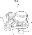
FIG. 2 is a bottom side perspective view of the ball joint according to the embodiment of the present disclosure; -
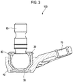
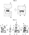
FIG. 3 is a cross-sectional view of the ball joint according to the embodiment of the present disclosure; -
FIG. 4 is a perspective view of a lower control arm equipped with the ball joint according to the embodiment of the present disclosure; -
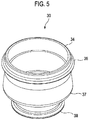
FIG. 5 is a perspective view of a case bush of the ball joint according to the embodiment of the present disclosure; -
FIG. 6 is a cross-sectional view of the case bush of the ball joint according to the embodiment of the present disclosure; -
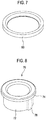
FIG. 7 is a perspective view of a cap of the ball joint according to the embodiment of the present disclosure; -
FIG. 8 is a perspective view of a bolt mounting bush; -
FIG. 9 is an explanatory view illustrating a process for manufacturing a ball joint mounting case through a manufacturing method according to an embodiment of the present disclosure; and -
FIG. 10 is an explanatory diagram of a ball joint manufacturing method according to an embodiment of the present disclosure. - Hereinafter, embodiments of the present disclosure will be described in detail with reference to the accompanying drawings.
- Referring to
FIGS. 1 to 3 , aball joint 100 according to an embodiment of the present disclosure may include: aball stud 10 made of a rigid body; abearing 20 that encloses the ball of theball stud 10 and supports theball stud 10 to be freely rotatable; acase bush 30 that accommodates a portion of theball stud 10 and thebearing 20; a balljoint mounting case 40 that accommodates thecase bush 30 and is fastened to a suspension arm (not illustrated); adust cover 50 that covers the upper portions of thecase bush 30 and the balljoint mounting case 40 so as to prevent foreign matter from infiltrating into the balljoint mounting case 40; aring clip 60 that fixes thedust cover 50 to the balljoint mounting case 40; at least onebolt mounting bush 70 inserted into and coupled to the balljoint mounting case 40; and acase cap 80 accommodated in thecase bush 30. - The ball
joint mounting case 40 may be molded using a CFRP. - The
case bush 30 may be formed of a steel material. - Referring to
FIG. 4 , theball joint 100 according to the embodiment of the present disclosure may be mounted on one end of a suspension arm of a vehicle, for example, one end of alower control arm 200. - That is, the
ball joint 100 may be mounted on one end of thelower control arm 200, afirst bush 210 may be mounted on the other end of thelower control arm 200, and asecond bush 220 may be mounted on a predetermined portion between theball joint 100 and thefirst bush 210. - The
lower control arm 200 may be connected to a knuckle of a wheel (not illustrated) through theball joint 100, and the first andsecond bushes lower control arm 200. - Referring to
FIGS. 5 and6 , thecase bush 30 inserted into the balljoint mounting case 40 and integrally coupled to the balljoint mounting case 40 includes acylindrical bush body 34 having abottom face 32 and an opening on the opposite side of thebottom face 32. - A ring-shaped
engagement protrusion 36 may be formed on the outer face of thebush body 34 so as to integrally protrude radially outwards, acircular rim 38 may be formed on thebottom face 32 to extend radially outwards, and acorner portion 37 protruding radially outwards from a predetermined portion of the outer face may be formed between theengagement protrusion 36 and therim 38. - The
engagement protrusion 36, thecorner portion 37, and therim 37 prevent axial separation between thecase bush 30 and the ball joint mountingcase 40, thereby increasing the coupling force of thecase bush 30 and the joint mountingcase 40. - In addition, since the
case bush 30 is inserted into the ball joint mountingcase 40, corrosion resistance can be improved even if thecase bush 30 is formed of a steel material. - As described below, since the ball joint mounting
case 40 is molded using an epoxy resin having a self-adhesive property, thecase bush 30 and the ball joint mountingcase 40 can be firmly coupled to each other without using a separate adhesive. - It is possible to improve the wettability on the metal surface of the
case bush 30 through a phosphoric acid anodizing treatment. - In addition, it is possible to improve corrosion resistance by applying an anti-corrosion primer.
- A
seating step 35, on which acase cap 80 is seated and supported, may be integrally formed on the inner face of thecase bush 30 to protrude radially inwards. - Referring to
FIG. 7 , thecase cap 80 may have a circular ring shape. - Referring to
FIG. 8 , thebolt mounting bush 70 may include acylindrical bush body 72 having openings on the opposite sides thereof. - A
rim 74 extending radially outwards is integrally formed on the outer face of thebush body 72, so that when thebolt mounting bush 70 is inserted into the ball joint mountingcase 40 so as to be integrally coupled thereto, axial separation between thebolt mounting bush 70 and the ball joint mountingcase 40 can be prevented, thereby increasing the coupling force. - At least one
engagement protrusion 76 may be integrally formed on the outer face of thebush body 72 to extend in the height direction and protrude radially outwards. - The
engagement protrusion 76 may serve to prevent rotational slip of thebolt mounting bush 70 when thebolt mounting bush 70 is inserted into and integrally coupled to the ball joint mountingcase 40. - It is also possible to improve wettability of the metal surface by a phosphoric acid anodizing treatment on the surface of the
bolt mounting bush 70 and it is possible to improve corrosion resistance by applying an anti-corrosion primer. - Referring to
FIG. 9 , the ball joint mountingcase 40 may be made of a CFRP through a hot press method. - That is, firstly a
charge 300 in which a product shape is considered is manufactured by using carbon chips, thecharge 300 is inserted into anupper mold 310 and alower mold 320, and then the ball joint mounting case may be manufactured by closing theupper mold 310 and applying heat and pressure to thecharge 300. - At this time, it is possible to integrally form the
bolt mounting bush 70 and thecase bush 30 with the ball joint mountingcase 40 by inserting thebolt mounting bush 70 and thecase bush 30 together into the mold. - As the carbon chips, carbon chips cut from a prepreg (UD tape) or a tow prepreg may be used.
- The carbon chips may be made using a mixture of carbon fiber (carbon fiber) and an epoxy resin (fast cure epoxy resin).
- The size of the carbon chips is preferably 10 mm to 80 mm in length and 3 mm to 30 mm in width.
- The weight of the prepreg (prepreg areal weight) is preferably 100 to 300 gsm (gram per square meter).
- Referring to
FIG. 10 , in the process sequence of the ball joint manufacturing method according to the embodiment of the present disclosure, firstly acase bush 30 and abolt mounting bush 70 are manufactured and inserted into a mold, acharge 300 is manufactured and inserted into the mold, and a ball joint mountingcase 40 is molded by applying heat and pressure in the state in which the mold is closed by mating anupper mold 310 and alower mold 320 with each other. - Then, the
case bush 30 and thebolt mounting bush 70 may be integrally coupled to the ball joint mountingcase 40. - Next, an assembly is made by assembling the
ball stud 10 and thebearing 20. At this time, it is possible to improve lubrication performance by applying lubricant such as grease to the inner face of the bearing 20 in advance. - Then, the assembly of the
ball stud 10 and thebearing 20 and thecase cap 80 are inserted into thecase bush 30, and are coupled by treating thecase bush 30 with swaging. - Finally, the
dust cover 50 is covered on the upper portion of theball stud 10 and fixed with theclip 60, and lubricant is injected as needed, thereby manufacturing the ball joint 100. - While embodiments of the present disclosure have been described, the present disclosure is not limited to the embodiments, and includes all modifications that are easily made by those skilled in the art to which the present disclosure belongs and are thus deemed equivalent to the present disclosure.
Claims (26)
- A ball joint comprising:a ball stud including a ball;a bearing configured to enclose and support the ball of the ball stud;a case bush configured to accommodate a portion of the ball stud and the bearing;a ball joint mounting case configured to accommodate the case bush and fastened to a suspension arm, the ball joint mounting case being made of a carbon fiber-reinforced plastic (CFRP); anda case cap accommodated in the case bush.
- The ball joint according to claim 1, further comprising:a dust cover configured to cover an upper portion of the case bush and an upper portion of the ball joint mounting case; anda ring clip configured to fix the dust cover to the ball joint mounting case.
- The ball joint according to claim 1, wherein at least one bolt mounting bush is inserted into and integrally coupled to the ball joint mounting case.
- The ball joint according to claim 1, wherein the suspension arm is a lower control arm, and the ball joint mounting case is mounted on one end of the lower control arm.
- The ball joint according to claim 1, wherein the case bush includes a cylindrical bush body having a bottom face and an opening on the opposite side of the bottom face.
- The ball joint according to claim 5, wherein a ring-shaped engagement protrusion is formed on an upper portion of an outer face of the bush body so as to integrally protrude radially outwards.
- The ball joint according to claim 6, wherein a circular rim is formed on the bottom face so as to extend radially outwards.
- The ball joint according to claim 7, wherein a corner portion protruding radially outward is formed at a predetermined portion of the outer face between the engagement protrusion and the rim.
- The ball joint according to claim 1, wherein the case bush is formed of a steel material and treated with phosphoric acid anodizing.
- The ball joint according to claim 9, wherein the case bush is applied with a corrosion-resistant primer.
- The ball joint according to claim 1, wherein a seating step is formed on an inner face of the case bush so as to protrude radially inwards such that the case cap is seated and supported on the seating step.
- The ball joint according to claim 3, wherein the bolt mounting bush includes a cylindrical bush body having openings on opposite sides thereof.
- The ball joint according to claim 12, wherein a rim is integrally formed on an upper portion of an outer face of the bush body so as to extend radially outwards.
- The ball joint according to claim 12, wherein at least one engagement protrusion is integrally formed on the outer face of the bush body so as to extend in a height direction and protrude radially outwards.
- The ball joint according to claim 3, wherein the bolt mounting bush is formed of a steel material, treated with phosphoric acid anodizing, and applied with a corrosion-resistant primer.
- The ball joint according to claim 1, wherein the ball joint mounting case is made of a carbon fiber-reinforced plastic through a hot press method.
- A method for manufacturing a ball joint, the method comprising:manufacturing at least one mounting bush and a case bush and integrally coupling the mounting bush and the case bush to a ball joint mounting case;manufacturing a ball stud including a ball and a bearing and coupling the bearing to the ball stud so as to enclose the ball; andmanufacturing a case cap and assembling by inserting the case cap into the case bush together with the assembly of the ball stud and the bearing.
- The method according to claim 17, wherein the ball joint mounting case is made of a carbon fiber-reinforced plastic.
- The method according to claim 18, wherein the ball joint mounting case is manufactured with the carbon fiber-reinforced plastic by a hot press method.
- The method according to claim 17, wherein a charge in which a product shape is considered is manufactured by using carbon chips, and the ball joint mounting case is manufactured by inserting the charge into a mold and applying heat and pressure to the charge.
- The method according to claim 20, wherein the carbon chips are cut from a prepreg (UD tape) or a tow prepreg.
- The method according to claim 20, wherein the carbon chips are made of a mixture of carbon fibers and an epoxy resin.
- The method according to claim 17, further comprising:
a step of covering the ball stud with a dust cover and then fixedly fitting a ring clip on the dust cover. - The method according to claim 17, wherein, in the coupling the bearing to the ball stud so as to enclose the ball, lubricant is injected.
- The method according to claim 23, wherein, in the step of covering the ball stud with the dust cover and then fixedly fitting the ring clip on the dust cover, lubricant is injected.
- The method according to claim 17, wherein, in the step of manufacturing the case cap and assembling by inserting the case cap into the case bush together with the assembly of the ball stud and the bearing, the case bush is treated with swaging.
Applications Claiming Priority (2)
| Application Number | Priority Date | Filing Date | Title |
|---|---|---|---|
| KR1020160014326A KR101857173B1 (en) | 2016-02-04 | 2016-02-04 | Ball joint and Manufacturing method thereof |
| PCT/KR2017/001206 WO2017135743A1 (en) | 2016-02-04 | 2017-02-03 | Ball joint and manufacturing method therefor |
Publications (2)
| Publication Number | Publication Date |
|---|---|
| EP3412480A1 true EP3412480A1 (en) | 2018-12-12 |
| EP3412480A4 EP3412480A4 (en) | 2019-09-11 |
Family
ID=59500076
Family Applications (1)
| Application Number | Title | Priority Date | Filing Date |
|---|---|---|---|
| EP17747788.2A Withdrawn EP3412480A4 (en) | 2016-02-04 | 2017-02-03 | Ball joint and manufacturing method therefor |
Country Status (5)
| Country | Link |
|---|---|
| US (1) | US20190152283A1 (en) |
| EP (1) | EP3412480A4 (en) |
| KR (1) | KR101857173B1 (en) |
| CN (1) | CN108602405A (en) |
| WO (1) | WO2017135743A1 (en) |
Families Citing this family (11)
| Publication number | Priority date | Publication date | Assignee | Title |
|---|---|---|---|---|
| KR101857170B1 (en) * | 2016-09-09 | 2018-05-16 | 주식회사 일진 | Knuckle of vehicle and manufacturing method thereof |
| KR102064287B1 (en) | 2017-09-13 | 2020-01-10 | 주식회사 일진 | Preform part and a method for manufacturing the suspension arm using the preform part |
| KR20200019032A (en) * | 2018-08-13 | 2020-02-21 | 주식회사 일진글로벌 | Wheel hub, wheel bearing assembly comprising same, and manufacturing method of wheel hub |
| JP7107149B2 (en) * | 2018-10-05 | 2022-07-27 | トヨタ自動車株式会社 | front lower arm |
| CN109334368A (en) * | 2018-10-18 | 2019-02-15 | 无锡市中亚减震器有限公司 | A kind of inner core of Triangular Arm |
| KR102075155B1 (en) * | 2018-12-14 | 2020-02-10 | 주식회사 일진 | Method and apparatus for manufacturing vehicle part of cfrp material |
| KR102244923B1 (en) * | 2019-07-25 | 2021-04-28 | 프로텍코리아 주식회사 | Manufacturing method of the Suspension arm for vehicle |
| US11254176B1 (en) * | 2019-08-14 | 2022-02-22 | Northstar Manufacturing Co., Inc. | Adjustable ball joint coupling |
| KR102339940B1 (en) * | 2019-12-27 | 2021-12-17 | 주식회사 일진 | Suspension arm for vehicle |
| US11845316B1 (en) | 2021-09-08 | 2023-12-19 | Northstar Manufacturing Co., Inc. | Adjustable pivot joint for vehicle suspensions |
| KR102652336B1 (en) | 2022-08-09 | 2024-03-29 | 서진산업 주식회사 | Fixing structure of Ball joint having screw combining type and Fixing method thereof |
Family Cites Families (15)
| Publication number | Priority date | Publication date | Assignee | Title |
|---|---|---|---|---|
| DE1075824B (en) * | 1953-12-08 | 1960-02-18 | Dearborn Mich Charles Samuel White (V St A) | Method for producing a ball joint bearing |
| US4856795A (en) * | 1987-07-21 | 1989-08-15 | Chemcast Corporation | Multiple durometer shield for ball joint |
| JPH09166129A (en) * | 1995-12-14 | 1997-06-24 | Toyota Motor Corp | Dust cover structure of ball joint |
| KR970042254U (en) * | 1995-12-21 | 1997-07-29 | Ball joint mounting structure | |
| JPH10151931A (en) * | 1996-09-30 | 1998-06-09 | Bridgestone Corp | Link rod for stabilizer and manufacture thereof |
| KR20020062493A (en) * | 2001-01-22 | 2002-07-26 | 주식회사 센트랄 | Manufacturing method of ball joint for vehicle |
| US20050281610A1 (en) * | 2004-06-04 | 2005-12-22 | Maclean Barry L | Composite link |
| DE102007015616B4 (en) * | 2007-03-29 | 2021-10-21 | Zf Friedrichshafen Ag | Connector for the articulated connection of components arranged in the chassis of a vehicle |
| JP5353099B2 (en) * | 2008-07-24 | 2013-11-27 | 東レ株式会社 | Manufacturing method of fiber reinforced plastic |
| KR20100116081A (en) * | 2009-04-21 | 2010-10-29 | 주식회사 일진 | Control arm of vehicle and manufacturing method thereof |
| JP5718620B2 (en) * | 2010-11-19 | 2015-05-13 | 日本発條株式会社 | Manufacturing method of stabilizer link |
| KR101274345B1 (en) * | 2011-07-07 | 2013-06-13 | 주식회사 센트랄 | A link structure and the manufacturing method and apparatus for the link structure |
| DE102011084163A1 (en) * | 2011-10-07 | 2013-04-11 | Zf Friedrichshafen Ag | Connecting arrangement for a vehicle |
| KR20140064004A (en) * | 2012-11-19 | 2014-05-28 | 현대자동차주식회사 | Structure for ball-and-socket joint of step link |
| WO2014192081A1 (en) * | 2013-05-28 | 2014-12-04 | 東レ株式会社 | Vehicle link component, and manufacturing method therefor |
-
2016
- 2016-02-04 KR KR1020160014326A patent/KR101857173B1/en active IP Right Grant
-
2017
- 2017-02-03 WO PCT/KR2017/001206 patent/WO2017135743A1/en active Application Filing
- 2017-02-03 US US16/074,586 patent/US20190152283A1/en not_active Abandoned
- 2017-02-03 CN CN201780009514.5A patent/CN108602405A/en active Pending
- 2017-02-03 EP EP17747788.2A patent/EP3412480A4/en not_active Withdrawn
Also Published As
| Publication number | Publication date |
|---|---|
| EP3412480A4 (en) | 2019-09-11 |
| KR20170092972A (en) | 2017-08-14 |
| US20190152283A1 (en) | 2019-05-23 |
| KR101857173B1 (en) | 2018-05-16 |
| WO2017135743A1 (en) | 2017-08-10 |
| CN108602405A (en) | 2018-09-28 |
Similar Documents
| Publication | Publication Date | Title |
|---|---|---|
| EP3412480A1 (en) | Ball joint and manufacturing method therefor | |
| EP3412479A1 (en) | Ball joint and manufacturing method therefor | |
| US10442262B2 (en) | Hybrid arm and method of manufacturing same | |
| EP3398795A2 (en) | Hybrid suspension arm for vechicle and manufacturing method thereof | |
| US20100084834A1 (en) | Connector piece for the articulated connection of components located in the suspension of a vehicle | |
| KR101888707B1 (en) | Method for producing a spherical sleeve joint | |
| US20130334841A1 (en) | Motor Vehicle Body With Stiffening Struts | |
| US11104196B2 (en) | Method for manufacturing hybrid suspension arm for vehicle using fixing pin and hybrid suspension arm manufactured by using same | |
| US10974559B2 (en) | Wheel suspension link | |
| KR20170025879A (en) | Strut bearing assembly for vehicle | |
| KR101779784B1 (en) | Strut bearing assembly for vehicle | |
| KR101855150B1 (en) | Strut bearing assembly for vehicle | |
| US20050167218A1 (en) | Composite helmet for body mount | |
| US20090020976A1 (en) | Bushing having high axial spring rate and method of manufacturing | |
| KR102392831B1 (en) | Installation structure of ball-joint and installation method thereof | |
| CN110014796B (en) | Integrated composite material mixed type damping tower | |
| KR101958433B1 (en) | Ball joint and hybrid suspension arm including same | |
| US20220297360A1 (en) | Trailing arm manufacturing method | |
| US20220297488A1 (en) | Trailing arm | |
| US20220297490A1 (en) | Trailing arm attachment portion structure | |
| US10315706B2 (en) | Adjustable hood-stop for a motor vehicle | |
| KR101609645B1 (en) | Bushing for automobiles | |
| KR101077631B1 (en) | Stabilizer link | |
| EP3421275A1 (en) | Stabilizer link for a vehicle suspension | |
| KR20190115740A (en) | Knuckle assembly for suspension of vehicle and method for manufacturing the same |
Legal Events
| Date | Code | Title | Description |
|---|---|---|---|
| STAA | Information on the status of an ep patent application or granted ep patent |
Free format text: STATUS: THE INTERNATIONAL PUBLICATION HAS BEEN MADE |
|
| PUAI | Public reference made under article 153(3) epc to a published international application that has entered the european phase |
Free format text: ORIGINAL CODE: 0009012 |
|
| STAA | Information on the status of an ep patent application or granted ep patent |
Free format text: STATUS: REQUEST FOR EXAMINATION WAS MADE |
|
| 17P | Request for examination filed |
Effective date: 20180904 |
|
| AK | Designated contracting states |
Kind code of ref document: A1 Designated state(s): AL AT BE BG CH CY CZ DE DK EE ES FI FR GB GR HR HU IE IS IT LI LT LU LV MC MK MT NL NO PL PT RO RS SE SI SK SM TR |
|
| AX | Request for extension of the european patent |
Extension state: BA ME |
|
| DAV | Request for validation of the european patent (deleted) | ||
| DAX | Request for extension of the european patent (deleted) | ||
| A4 | Supplementary search report drawn up and despatched |
Effective date: 20190812 |
|
| RIC1 | Information provided on ipc code assigned before grant |
Ipc: B29C 70/46 20060101ALI20190806BHEP Ipc: B29L 31/04 20060101ALN20190806BHEP Ipc: B29K 105/12 20060101ALN20190806BHEP Ipc: B29C 43/02 20060101AFI20190806BHEP Ipc: B29C 70/12 20060101ALI20190806BHEP Ipc: F16C 11/06 20060101ALI20190806BHEP Ipc: B29K 63/00 20060101ALN20190806BHEP Ipc: B29K 307/04 20060101ALN20190806BHEP Ipc: B29C 45/14 20060101ALI20190806BHEP Ipc: B29C 43/00 20060101ALI20190806BHEP Ipc: B60G 7/00 20060101ALI20190806BHEP |
|
| STAA | Information on the status of an ep patent application or granted ep patent |
Free format text: STATUS: THE APPLICATION IS DEEMED TO BE WITHDRAWN |
|
| 18D | Application deemed to be withdrawn |
Effective date: 20200310 |