EP3412447A1 - Passive radiative cooling of window structures - Google Patents
Passive radiative cooling of window structures Download PDFInfo
- Publication number
- EP3412447A1 EP3412447A1 EP18173457.5A EP18173457A EP3412447A1 EP 3412447 A1 EP3412447 A1 EP 3412447A1 EP 18173457 A EP18173457 A EP 18173457A EP 3412447 A1 EP3412447 A1 EP 3412447A1
- Authority
- EP
- European Patent Office
- Prior art keywords
- coating
- infrared radiation
- thermal
- glass
- window
- Prior art date
- Legal status (The legal status is an assumption and is not a legal conclusion. Google has not performed a legal analysis and makes no representation as to the accuracy of the status listed.)
- Granted
Links
Images



Classifications
-
- B—PERFORMING OPERATIONS; TRANSPORTING
- B32—LAYERED PRODUCTS
- B32B—LAYERED PRODUCTS, i.e. PRODUCTS BUILT-UP OF STRATA OF FLAT OR NON-FLAT, e.g. CELLULAR OR HONEYCOMB, FORM
- B32B17/00—Layered products essentially comprising sheet glass, or glass, slag, or like fibres
- B32B17/06—Layered products essentially comprising sheet glass, or glass, slag, or like fibres comprising glass as the main or only constituent of a layer, next to another layer of a specific material
- B32B17/10—Layered products essentially comprising sheet glass, or glass, slag, or like fibres comprising glass as the main or only constituent of a layer, next to another layer of a specific material of synthetic resin
-
- B—PERFORMING OPERATIONS; TRANSPORTING
- B32—LAYERED PRODUCTS
- B32B—LAYERED PRODUCTS, i.e. PRODUCTS BUILT-UP OF STRATA OF FLAT OR NON-FLAT, e.g. CELLULAR OR HONEYCOMB, FORM
- B32B17/00—Layered products essentially comprising sheet glass, or glass, slag, or like fibres
- B32B17/06—Layered products essentially comprising sheet glass, or glass, slag, or like fibres comprising glass as the main or only constituent of a layer, next to another layer of a specific material
- B32B17/10—Layered products essentially comprising sheet glass, or glass, slag, or like fibres comprising glass as the main or only constituent of a layer, next to another layer of a specific material of synthetic resin
- B32B17/10005—Layered products essentially comprising sheet glass, or glass, slag, or like fibres comprising glass as the main or only constituent of a layer, next to another layer of a specific material of synthetic resin laminated safety glass or glazing
- B32B17/10009—Layered products essentially comprising sheet glass, or glass, slag, or like fibres comprising glass as the main or only constituent of a layer, next to another layer of a specific material of synthetic resin laminated safety glass or glazing characterized by the number, the constitution or treatment of glass sheets
- B32B17/10036—Layered products essentially comprising sheet glass, or glass, slag, or like fibres comprising glass as the main or only constituent of a layer, next to another layer of a specific material of synthetic resin laminated safety glass or glazing characterized by the number, the constitution or treatment of glass sheets comprising two outer glass sheets
- B32B17/10045—Layered products essentially comprising sheet glass, or glass, slag, or like fibres comprising glass as the main or only constituent of a layer, next to another layer of a specific material of synthetic resin laminated safety glass or glazing characterized by the number, the constitution or treatment of glass sheets comprising two outer glass sheets with at least one intermediate layer consisting of a glass sheet
-
- B—PERFORMING OPERATIONS; TRANSPORTING
- B32—LAYERED PRODUCTS
- B32B—LAYERED PRODUCTS, i.e. PRODUCTS BUILT-UP OF STRATA OF FLAT OR NON-FLAT, e.g. CELLULAR OR HONEYCOMB, FORM
- B32B17/00—Layered products essentially comprising sheet glass, or glass, slag, or like fibres
- B32B17/06—Layered products essentially comprising sheet glass, or glass, slag, or like fibres comprising glass as the main or only constituent of a layer, next to another layer of a specific material
- B32B17/10—Layered products essentially comprising sheet glass, or glass, slag, or like fibres comprising glass as the main or only constituent of a layer, next to another layer of a specific material of synthetic resin
- B32B17/10005—Layered products essentially comprising sheet glass, or glass, slag, or like fibres comprising glass as the main or only constituent of a layer, next to another layer of a specific material of synthetic resin laminated safety glass or glazing
- B32B17/10165—Functional features of the laminated safety glass or glazing
- B32B17/10174—Coatings of a metallic or dielectric material on a constituent layer of glass or polymer
-
- B—PERFORMING OPERATIONS; TRANSPORTING
- B60—VEHICLES IN GENERAL
- B60J—WINDOWS, WINDSCREENS, NON-FIXED ROOFS, DOORS, OR SIMILAR DEVICES FOR VEHICLES; REMOVABLE EXTERNAL PROTECTIVE COVERINGS SPECIALLY ADAPTED FOR VEHICLES
- B60J1/00—Windows; Windscreens; Accessories therefor
- B60J1/001—Double glazing for vehicles
-
- B—PERFORMING OPERATIONS; TRANSPORTING
- B60—VEHICLES IN GENERAL
- B60J—WINDOWS, WINDSCREENS, NON-FIXED ROOFS, DOORS, OR SIMILAR DEVICES FOR VEHICLES; REMOVABLE EXTERNAL PROTECTIVE COVERINGS SPECIALLY ADAPTED FOR VEHICLES
- B60J3/00—Antiglare equipment associated with windows or windscreens; Sun visors for vehicles
- B60J3/007—Sunglare reduction by coatings, interposed foils in laminar windows, or permanent screens
-
- C—CHEMISTRY; METALLURGY
- C03—GLASS; MINERAL OR SLAG WOOL
- C03C—CHEMICAL COMPOSITION OF GLASSES, GLAZES OR VITREOUS ENAMELS; SURFACE TREATMENT OF GLASS; SURFACE TREATMENT OF FIBRES OR FILAMENTS MADE FROM GLASS, MINERALS OR SLAGS; JOINING GLASS TO GLASS OR OTHER MATERIALS
- C03C17/00—Surface treatment of glass, not in the form of fibres or filaments, by coating
- C03C17/34—Surface treatment of glass, not in the form of fibres or filaments, by coating with at least two coatings having different compositions
- C03C17/42—Surface treatment of glass, not in the form of fibres or filaments, by coating with at least two coatings having different compositions at least one coating of an organic material and at least one non-metal coating
-
- E—FIXED CONSTRUCTIONS
- E06—DOORS, WINDOWS, SHUTTERS, OR ROLLER BLINDS IN GENERAL; LADDERS
- E06B—FIXED OR MOVABLE CLOSURES FOR OPENINGS IN BUILDINGS, VEHICLES, FENCES OR LIKE ENCLOSURES IN GENERAL, e.g. DOORS, WINDOWS, BLINDS, GATES
- E06B3/00—Window sashes, door leaves, or like elements for closing wall or like openings; Layout of fixed or moving closures, e.g. windows in wall or like openings; Features of rigidly-mounted outer frames relating to the mounting of wing frames
- E06B3/66—Units comprising two or more parallel glass or like panes permanently secured together
- E06B3/67—Units comprising two or more parallel glass or like panes permanently secured together characterised by additional arrangements or devices for heat or sound insulation or for controlled passage of light
- E06B3/6715—Units comprising two or more parallel glass or like panes permanently secured together characterised by additional arrangements or devices for heat or sound insulation or for controlled passage of light specially adapted for increased thermal insulation or for controlled passage of light
-
- E—FIXED CONSTRUCTIONS
- E06—DOORS, WINDOWS, SHUTTERS, OR ROLLER BLINDS IN GENERAL; LADDERS
- E06B—FIXED OR MOVABLE CLOSURES FOR OPENINGS IN BUILDINGS, VEHICLES, FENCES OR LIKE ENCLOSURES IN GENERAL, e.g. DOORS, WINDOWS, BLINDS, GATES
- E06B9/00—Screening or protective devices for wall or similar openings, with or without operating or securing mechanisms; Closures of similar construction
- E06B9/24—Screens or other constructions affording protection against light, especially against sunshine; Similar screens for privacy or appearance; Slat blinds
-
- C—CHEMISTRY; METALLURGY
- C03—GLASS; MINERAL OR SLAG WOOL
- C03C—CHEMICAL COMPOSITION OF GLASSES, GLAZES OR VITREOUS ENAMELS; SURFACE TREATMENT OF GLASS; SURFACE TREATMENT OF FIBRES OR FILAMENTS MADE FROM GLASS, MINERALS OR SLAGS; JOINING GLASS TO GLASS OR OTHER MATERIALS
- C03C2217/00—Coatings on glass
- C03C2217/20—Materials for coating a single layer on glass
- C03C2217/21—Oxides
- C03C2217/211—SnO2
-
- C—CHEMISTRY; METALLURGY
- C03—GLASS; MINERAL OR SLAG WOOL
- C03C—CHEMICAL COMPOSITION OF GLASSES, GLAZES OR VITREOUS ENAMELS; SURFACE TREATMENT OF GLASS; SURFACE TREATMENT OF FIBRES OR FILAMENTS MADE FROM GLASS, MINERALS OR SLAGS; JOINING GLASS TO GLASS OR OTHER MATERIALS
- C03C2217/00—Coatings on glass
- C03C2217/20—Materials for coating a single layer on glass
- C03C2217/21—Oxides
- C03C2217/24—Doped oxides
- C03C2217/241—Doped oxides with halides
-
- C—CHEMISTRY; METALLURGY
- C03—GLASS; MINERAL OR SLAG WOOL
- C03C—CHEMICAL COMPOSITION OF GLASSES, GLAZES OR VITREOUS ENAMELS; SURFACE TREATMENT OF GLASS; SURFACE TREATMENT OF FIBRES OR FILAMENTS MADE FROM GLASS, MINERALS OR SLAGS; JOINING GLASS TO GLASS OR OTHER MATERIALS
- C03C2218/00—Methods for coating glass
- C03C2218/10—Deposition methods
- C03C2218/11—Deposition methods from solutions or suspensions
- C03C2218/116—Deposition methods from solutions or suspensions by spin-coating, centrifugation
-
- E—FIXED CONSTRUCTIONS
- E06—DOORS, WINDOWS, SHUTTERS, OR ROLLER BLINDS IN GENERAL; LADDERS
- E06B—FIXED OR MOVABLE CLOSURES FOR OPENINGS IN BUILDINGS, VEHICLES, FENCES OR LIKE ENCLOSURES IN GENERAL, e.g. DOORS, WINDOWS, BLINDS, GATES
- E06B9/00—Screening or protective devices for wall or similar openings, with or without operating or securing mechanisms; Closures of similar construction
- E06B9/24—Screens or other constructions affording protection against light, especially against sunshine; Similar screens for privacy or appearance; Slat blinds
- E06B2009/2417—Light path control; means to control reflection
Definitions
- the present disclosure relates to passive cooling. More specifically, this disclosure relates to passive radiative cooling of transparent structures, such as glass windows.
- glazing with transmittance in the visible spectrum i.e., optically transparent
- structural functionality are desirable for protection against mechanical impact.
- automotive glazing coatings with functionalities such as reflecting sunlight, embedding antennas, self-defrosting by passing current through a coating, and conserving energy (e.g., in electric vehicles).
- Such applications have driven research in advanced materials, including glasses.
- SHGC solar heat gain coefficient
- the second temperature contribution involves a balance between thermal radiation emitted by the window to its surroundings, and thermal radiation absorbed by the windowpane from the window's surroundings.
- One embodiment described herein provides an apparatus for passive cooling via selective radiative emission.
- This apparatus includes a transparent substrate and a coating on the transparent substrate for radiating heat from the substrate.
- the coating is configured to emit more thermal infrared radiation to the atmosphere than an amount of infrared radiation that can be received by the coating.
- the coating has a thermal blackbody emissivity coefficient of at least 0.9 corresponding to an infrared radiation wavelength range.
- the infrared radiation wavelength range comprises wavelengths in an atmospheric transparency window of 8 micrometers to 13 micrometers.
- the coating includes a polymer.
- the coating includes one or more polymers selected from the group consisting of: ethyl cellulose, poly ethyl methacrylate (PEMA), poly methyl methacrylate (PMMA), polyvinyl butyral (PVB), cellulose acetate, polyethylene, polypropylene, polyethylene terephthalate (PET), polyethylene naphthalate (PEN), polyesters, polyacrylic acid, polycarbonates, and a copolymer mixture.
- PEMA poly ethyl methacrylate
- PMMA poly methyl methacrylate
- PVB polyvinyl butyral
- cellulose acetate polyethylene
- PET polyethylene terephthalate
- PEN polyethylene naphthalate
- polyesters polyacrylic acid, polycarbonates, and a copolymer mixture.
- the transparent substrate comprises a piece of glass, and the chemical coating is coated on the piece of glass.
- the apparatus further includes a second piece of glass and a second coating on the second piece of glass for radiating additional heat.
- the second piece of glass is stacked with the first piece of glass.
- the apparatus further includes one or more layers of reflective coating for reflecting incident sunlight.
- the transparent substrate is part of a window, an automotive window, or an automotive sunroof.
- the coating is not coupled to a liquid coolant source or an electrical source.
- Embodiments of the present invention provide a system, apparatus, and method for passive cooling of a transparent substrate via selective radiative emission.
- the disclosed apparatus uses an optically transparent chemical coating that can cool a transparent substrate, such as a window, even while exposed to sunshine, thereby reducing the need for a liquid coolant or electrical source.
- embodiments of the present invention use a material that can emit more thermal infrared (IR) radiation than it receives from the atmosphere, even at ambient temperature. In the absence of sunlight, the system can reach a temperature below the ambient one.
- IR thermal infrared
- the system can decrease the interior temperature in an enclosure (such as a room or car interior) without the need for any electricity or liquid coolant. It is estimated that the present system can provide additional cooling capacity compared with conventional window glazing. This cooling effect can be obtained without alteration of the glass' visible-wavelength transmittance or its color. Moreover, the disclosed solution can use thin, inexpensive polymer films, and hence is cost-effective and scalable.
- FIG. 1 shows contributions to heating and cooling in an interior space enclosed by an optically transparent window, such as the interior of an automobile with a sunroof 102.
- Table 1 further summarizes these contributions to heating and cooling in the sunroof 102, and lists their net effect on the temperature inside the car, T car .
- sunlight 104 shines on sunroof 102 and can be absorbed by sunroof 102.
- Sunlight 106 can also pass through the sunroof to the interior of the car and be absorbed there.
- the car, the sunroof, and the car's environment can all radiate thermally (i.e., corresponding to a blackbody radiation spectrum at their current temperatures, typically peaking in the IR range).
- thermal radiation 108 from the atmosphere and the car's external surroundings can arrive at sunroof 102
- thermal radiation 110 from the car's interior can arrive at sunroof 102.
- sunroof 102 absorbs radiation 108 and 110, it contributes to raising T car .
- Sunroof 102 can also emit external thermal radiation 112 to the car's environment and internal thermal radiation 114 to the car's interior.
- convection currents outside the car 116 and inside the car 118 contribute to lowering T car by carrying heat from the car to the sunroof when T car > T glass , and from the sunroof to the environment when T glass > T ambient .
- Table 1 also lists properties of the sunroof that could be engineered to tune each heating and cooling contribution in order to keep T car low.
- the thermal emissivity coefficient of the sunroof in the IR wavelength region can affect T car .
- the sunroof's absorbance and transmittance in the solar wavelengths affects T car .
- the sunroof's temperature T glass would affect T car .
- T glass is not a property of the sunroof that can be directly engineered, it is determined by a balance between heating and cooling contributions similar to the ones discussed above, and therefore can be influenced by properties like the sunroof's thermal emissivity coefficient and solar absorbance and transmittance.
- Table 1 Contributions to heating and cooling of a car equipped with an automotive sunroof.
- thermal radiation 112 and 114 from the sunroof carries heat away, and therefore tuning the emissivity could help lower T car , as shown in Table 1.
- a body's thermal emissivity and absorptivity (also known as absorptance) coefficients are typically equal.
- thermal emission is balanced by equal thermal absorption, which would bring the sunroof into thermal equilibrium with the radiation from its environment.
- the Earth's atmosphere has a transparency range of wavelengths (also called the atmospheric or sky transparency window), in which the atmosphere has low thermal emissivity and absorptivity. Therefore, by selectively emitting in this wavelength range, the present invention can emit heat that will not be absorbed by its surroundings, engendering a net outflow of heat, as will be described in more detail below.
- the system can produce a negative heat flow (resulting in cooling) if the window is engineered to emit more radiation than it absorbs. This can be accomplished if the window emits radiation at wavelengths where the atmosphere is relatively transparent (such as the sky transparency window).
- the system operates by virtue of having a selectively enhanced thermal emissivity in an infrared (IR) radiation wavelength range, which may correspond to the Earth's atmospheric transparency window.
- IR infrared
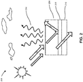
- FIG. 2 shows the operational principle of passive radiative cooling, in accordance with embodiments of the present invention.
- sunlight 202 can arrive at window or sunroof 200 containing selectively emissive film 204 as part of the passive cooling system.
- Film 204 can transmit sunlight, which then arrives at low-emissivity reflective coating 206.
- Low-emissivity coating 206 can reflect broadband sunlight 208, especially in the IR wavelengths.
- Coating 206 thereby prevents substantial amounts of solar IR radiation from passing through window or sunroof 200 and heating the enclosed room or car.
- visible-wavelength range sunlight 212 can pass through coating 206 and glass substrate 210 into the enclosed space, thereby allowing a user to see through the window.
- selectively emissive film 204 can absorb thermal radiation from both the enclosed space and the exterior environment.
- Film 204 can be configured to absorb and emit thermal radiation 214 selectively, as described above, in order to maintain a non-equilibrium, directed heat flow, and cool the system.
- the system has a high emissivity coefficient over the atmospheric transparency window, which corresponds to wavelengths 8 ⁇ m ⁇ ⁇ ⁇ 13 ⁇ m. Due to these desirable characteristics, the system can emit strong thermal radiation in the atmospheric transparency window, which is a range of wavelengths that is unlikely to be absorbed by the atmosphere or other surroundings. Specifically, since the sky is relatively transparent to radiation in these wavelengths, upward-emitted thermal radiation 214 is likely to continue propagating for great distances, possibly through the atmosphere and on to outer space. As a result, system 200 can maintain a non-equilibrium state, emitting 214 to its environment more thermal radiation than it receives in the atmospheric transparency window.
- Embodiments of the present invention improve significantly over existing systems by implementing the passive radiative cooling principles described above with inexpensive materials, without any need for complex techniques such as lithography. Moreover, the present system can achieve superior passive cooling to other systems, can cool effectively even when exposed to intense sunlight, and is optically transparent.
- FIG. 3 illustrates exemplary polymers and presents a schematic diagram of their vibrational excitations.
- polymers such as polycarbonate 304, polyethylene terephthalate (PET) 306, and cellulose acetate 308 have specific vibrational spectra. These spectra correspond to specific frequencies at which the molecular structures of the polymers have vibrational modes. Therefore, when excited thermally, polymers such as 304, 306, and 308 can emit IR radiation at these frequencies.
- a desirable polymer film can have high visible transmittance, low solar absorbance, and average emissivity > 0.9 in the 8-13 ⁇ m sky transparency window.
- polymers satisfying these requirements are PET, cellulose acetate, polycarbonate and ethyl cellulose. (Note that these polymers have high emissivity > 0.9 weighted for thermal radiation from inside the room).
- the selectively emissive chemical coating may include one or more of: polycarbonate, PET, polymethyl methacrylate, polyacrylic acid, polyethylene, polypropylene, cellulose acetate, ethyl cellulose, and a copolymer mixture. Note that the choice of an ideal polymer might depend on the intended temperature of the pane and atmospheric conditions. In some cases, one might want a broadband emitter. If other cases, one might want an emitter that selectively emits in the 8-13 ⁇ m window.
- the system can contain a polymer film on the outer surface of the glazing, i.e. facing the sky or exterior environment.
- the thickness of the polymer may range from 5 ⁇ m to 2000 ⁇ m. (Note that the polymer film thickness is a performance-determining factor, and thicknesses in the range 20 ⁇ m to 500 ⁇ m have been shown to work well).
- the system may be arranged into a layered structure containing the selectively emissive film, the glazing, and other components, as discussed below.
- This section describes details of the structure of the present system, including how the selectively emissive coating can be constructed.
- FIG. 4A shows an exemplary layered structure 400 of a passive radiative cooling system, according to one embodiment of the present invention.
- structure 400 contains a float glass substrate 402, which may be a part of a window, automotive sunroof, etc. Adjacent to substrate 402, structure 400 contains a layer of pyrolytic low-emissivity coating 404.
- Pyrolytic low-emissivity coating 404 may contain a transparent conducting oxide (TCO) such as fluorine doped tin oxide (FTO), or another low-emissivity coating.
- Structure 400 then contains an acrylic adhesive 406 to bond the selectively emissive chemical coating 408 to the structure.
- the structure contains a layer (e.g., 50 ⁇ m) of PET 408 as the selectively emissive chemical coating. Note that this coating is typically located closest to the exterior face of the window, i.e. facing the sky.
- FIG. 4B shows an exemplary layered structure 410 of a passive radiative cooling system, according to one embodiment of the present invention.
- structure 410 contains a 500 ⁇ m layer of polycarbonate 418 as the selectively emissive chemical coating, instead of 50 ⁇ m of PET.
- Structure 410 contains float glass substrate 412, which may be a part of a window, etc.
- Structure 410 contains a layer of pyrolytic low-emissivity coating 414 adjacent to glass 412.
- Structure 410 further contains an acrylic adhesive 416 and a layer (e.g., 500 ⁇ m) of polycarbonate 418 as the selectively emissive chemical coating.
- FIG. 4C shows an exemplary layered structure 420 of a passive radiative cooling system, according to one embodiment of the present invention.
- structure 420 may contain an infrared reflective thin metal multilayer coating 424.
- Such a coating can reflect a high proportion of the incident sunlight, thereby producing significant additional cooling.
- coating 424 can be strongly reflective at solar infrared wavelengths, the system can nevertheless have strong absorption at thermal IR wavelengths, particularly those in the sky transparency window.
- Structure 420 contains float glass substrate 422, and adjacent to float glass 422 contains the thin metal multilayer 424. Structure 420 also contains acrylic adhesive 426 and polycarbonate layer 428 as the selectively emissive chemical coating.
- FIGs. 4D and 4E show exemplary layered structures 430 and 450 of a passive radiative cooling system, according to embodiments of the present invention.
- Structures 430 and 450 are similar to structures 410 and 420, respectively.
- structures 430 and 450 contain an additional selectively emissive PET coating on the inside (shown as the bottom) of the respective layer stacks. These additional coatings function to absorb additional IR radiation from the inside enclosure (e.g., the interior of a car or room enclosed by the present invention) and can significantly enhance the system's net cooling effect.
- the layer structure for the inner coating can be similar to the outer one.
- structure 430 can contain an interior selectively emissive chemical coating layer 432 (e.g., 50 ⁇ m of PET), and a layer of acrylic adhesive 434 to adhere coating 432 to the structure.
- Structure 430 also contains float glass 436 and a layer of pyrolytic low-emissivity coating 438.
- structure 430 can contain another acrylic adhesive 440 and a layer (e.g., 500 ⁇ m) of polycarbonate 442 as the exterior selectively emissive chemical coating.
- Structure 450 can contain an interior selectively emissive chemical coating layer 452 (e.g., 50 ⁇ m of PET), and a layer of acrylic adhesive 454 to adhere coating 452 to the structure. Structure 450 can also contain float glass 456, and adjacent to float glass 456 can contain thin metal multilayer 458. Structure 450 further contains acrylic adhesive 460 and polycarbonate layer 462 (e.g., 500 ⁇ m) as the selectively emissive chemical coating.
- an interior selectively emissive chemical coating layer 452 e.g., 50 ⁇ m of PET
- acrylic adhesive 454 to adhere coating 452 to the structure.
- Structure 450 can also contain float glass 456, and adjacent to float glass 456 can contain thin metal multilayer 458. Structure 450 further contains acrylic adhesive 460 and polycarbonate layer 462 (e.g., 500 ⁇ m) as the selectively emissive chemical coating.
- the layer structures may also contain a thin, protective outer glass layer, e.g. 0.5-2 mm of alkali-aluminosilicate based toughened glass glass or float glass, to prevent abrasion. By protecting the polymer from being damaged by scratching, impacts, etc., this additional glass can improve the system's durability.
- a thin, protective outer glass layer e.g. 0.5-2 mm of alkali-aluminosilicate based toughened glass glass or float glass, to prevent abrasion.
- Such protective layers would be located outermost in the layer structure (i.e., at the top of the structures shown in FIGs. 4A-4E ). When sufficiently thin, such outer glass layers can be included, while still maintaining the desired cooling properties of the selectively emissive coating.
- the aforementioned glass types are often found to be non-transparent in the wavelength range greater than 5 ⁇ m, which might not be ideal for infrared transmission. For more optimized thermal performance, one can use a more infrared-transparent
- the layer structures as in FIGs. 4A-4E can be assembled by applying the polymer film directly onto the glass (by spin coating, doctor blading, slotted die coating, etc.).
- the structures can be assembled by attaching the film to the glass with acrylic adhesive (e.g., optical-grade clear acrylic adhesives), as shown.
- FIG. 5A shows an exemplary emissivity measurement of the passive radiative cooling system, according to one embodiment of the present invention.
- the system has a high thermal blackbody emissivity coefficient ⁇ > 0.8 over a range of wavelengths 3 ⁇ m ⁇ ⁇ ⁇ 15 ⁇ m.
- ⁇ is high over the atmospheric transparency window 510, which has wavelengths 8 ⁇ m ⁇ ⁇ ⁇ 13 ⁇ m. Due to these desirable properties, the system can emit thermal radiation strongly in the window 510, a range of wavelengths that is unlikely to be absorbed by the atmosphere or other surroundings. As a result, the system can maintain a non-equilibrium state, emitting more thermal radiation to its environment than it receives in the atmospheric transparency window.
- the system does not need to maintain a uniformly high emissivity throughout the entire spectrum of relevant wavelengths.
- This relevant region may be roughly identified as the solar spectrum, 250 nm to 2.5 ⁇ m, through the IR thermal wavelengths, 5 ⁇ m to 20 ⁇ m).
- the system is transparent to visible light, in order to allow users to see through the window or other glazing.
- FIG. 5B illustrates an exemplary transmittance measurement of the passive radiative cooling system, according to embodiments of the present invention. Also shown is the range of visible wavelengths 550, running from 400 nm to 700 nm. As shown, the system has a high transmittance coefficient of greater than 80% in the visible spectrum.
- FIGs. 5A and 5B demonstrate that the system can have high transmittance in the visible spectrum 550, while simultaneously having high emissivity in the atmospheric transparency window 510. This unique combination of properties allows the system to perform better than existing systems at passive cooling, while simultaneously being optically transparent.
- FIG. 6 shows exemplary cooling effects, based on experimental results using the passive radiative cooling system.
- Scheme 1 makes use of a thin layer (e.g., 50 ⁇ m) of PET as the selectively emissive chemical coating and contains a layer of pyrolytic low-emissivity coating, as in example structure 400 shown in FIG. 4A .
- Scheme 2 instead uses a thicker layer (e.g., 500 ⁇ m) of polycarbonate as the chemical coating, and also contains a layer of pyrolytic low-emissivity coating, as in structure 410 shown in FIG. 4B .
- Scheme 3 contains the thicker layer of polycarbonate as the chemical coating, but contains a reflective thin metal multilayer coating instead of the pyrolytic low-emissivity coating, as in exemplary structure 420 shown in FIG. 4C .
- scheme 4 contains both an exterior and an interior layer of selectively emissive coating.
- Scheme 4 can further contain either pyrolytic low-emissivity coating, as in structure 430 shown in FIG. 4D , or reflective thin metal multilayer coating, as in structure 450 shown in FIG. 4E .
- schemes 1 through 3 of the present invention have been measured to achieve from 3° to 11° C (20° F) cooling in sunlight, compared to a control system.
- Scheme 4 has been measured to achieve 2° C additional cooling (not shown) relative to scheme 2 in the embodiment of FIG. 3D with top and bottom layers of high-emissivity chemical coating and a layer of pyrolytic low-emissivity coating/FTO.
- Scheme 4 is likewise projected to achieve a total of 13° C (23° F) cooling vs. the control, in the exemplary embodiment of FIG. 4E with top and bottom layers of high-emissivity coating and an optically reflective thin metal multilayer coating.
- the present invention achieves extraordinary cooling of a transparent substrate in ambient sunlight, without input of electricity or liquid coolants required.
- the passive cooling system and methods are not limited by the present disclosure, and may be used for any application.
- the disclosed passive cooling system may be used as part of an automotive windshield or rear or side window, a commercial or residential window, a transparent or translucent wall or structure, transparent electronics, glasses, sunglasses or other wearable items, a container for food or biological matter, or any application known or later developed.
- the passive cooling system can be manufactured either by applying the polymer film directly onto glass (e.g., by spin coating), or attaching to the glass with acrylic adhesive (e.g., optical-grade clear acrylic adhesives from 3M).
- acrylic adhesive e.g., optical-grade clear acrylic adhesives from 3M.
- the manufacturing methods for the optional inner surface are similar.
Landscapes
- Engineering & Computer Science (AREA)
- Structural Engineering (AREA)
- Chemical & Material Sciences (AREA)
- Mechanical Engineering (AREA)
- Civil Engineering (AREA)
- Architecture (AREA)
- Life Sciences & Earth Sciences (AREA)
- Chemical Kinetics & Catalysis (AREA)
- General Chemical & Material Sciences (AREA)
- Geochemistry & Mineralogy (AREA)
- Materials Engineering (AREA)
- Organic Chemistry (AREA)
- Laminated Bodies (AREA)
- Surface Treatment Of Glass (AREA)
Abstract
Description
- The present disclosure relates to passive cooling. More specifically, this disclosure relates to passive radiative cooling of transparent structures, such as glass windows.
- As electronics and communication technologies advance, and research proceeds in flexible and transparent electronics, there is an increasing demand for transparent materials to perform optical, thermal, mechanical, and/or electrical functions. Particularly, functional glass and transparent materials are needed for applications including automotive sunroofs, windshields, windows, as well as other applications.
- For example, glazing with transmittance in the visible spectrum (i.e., optically transparent) and structural functionality are desirable for protection against mechanical impact. Similarly, there is a demand for automotive glazing coatings with functionalities such as reflecting sunlight, embedding antennas, self-defrosting by passing current through a coating, and conserving energy (e.g., in electric vehicles). Such applications have driven research in advanced materials, including glasses.
- By contrast, although reducing the cost of cooling with air conditioning (e.g., in a vehicle with a sunroof) is commonplace and widespread, additional cooling technologies based on glazing is highly desirable. When considering the heat balance of a window in a hot climate, there are two major contributions that affect the interior temperature (e.g., inside a car or building). The first contribution is the amount of solar radiation transmitted through the window, which contributes to heating objects in the interior. This is quantified by the solar heat gain coefficient (SHGC) of the window or glazing. Window films or coatings on glass that directly modify the SHGC are commercially available. In fact, in existing active glazing systems for hot climates, thermal management is typically approached in this way, i.e. by decreasing the SHGC.
- The second temperature contribution involves a balance between thermal radiation emitted by the window to its surroundings, and thermal radiation absorbed by the windowpane from the window's surroundings.
- One embodiment described herein provides an apparatus for passive cooling via selective radiative emission. This apparatus includes a transparent substrate and a coating on the transparent substrate for radiating heat from the substrate. The coating is configured to emit more thermal infrared radiation to the atmosphere than an amount of infrared radiation that can be received by the coating.
- In a variation on this embodiment, the coating has a thermal blackbody emissivity coefficient of at least 0.9 corresponding to an infrared radiation wavelength range.
- In a variation on this embodiment, the infrared radiation wavelength range comprises wavelengths in an atmospheric transparency window of 8 micrometers to 13 micrometers.
- In a variation on this embodiment, the coating includes a polymer.
- In a variation on this embodiment, the coating includes one or more polymers selected from the group consisting of: ethyl cellulose, poly ethyl methacrylate (PEMA), poly methyl methacrylate (PMMA), polyvinyl butyral (PVB), cellulose acetate, polyethylene, polypropylene, polyethylene terephthalate (PET), polyethylene naphthalate (PEN), polyesters, polyacrylic acid, polycarbonates, and a copolymer mixture.
- In a variation on this embodiment, the transparent substrate comprises a piece of glass, and the chemical coating is coated on the piece of glass.
- In a variation on this embodiment, the apparatus further includes a second piece of glass and a second coating on the second piece of glass for radiating additional heat. The second piece of glass is stacked with the first piece of glass.
- In a variation on this embodiment, the apparatus further includes one or more layers of reflective coating for reflecting incident sunlight.
- In a variation on this embodiment, the transparent substrate is part of a window, an automotive window, or an automotive sunroof.
- In a variation on this embodiment, the coating is not coupled to a liquid coolant source or an electrical source.
-
-
FIG. 1 shows contributions to heating and cooling in an automotive sunroof. -
FIG. 2 shows an operational principle of passive radiative cooling, in accordance with embodiments of the present invention. -
FIG. 3 illustrates exemplary polymers and presents a schematic diagram of their vibrational excitations. -
FIG. 4A shows an exemplary layered structure of a passive radiative cooling system, according to one embodiment of the present invention. -
FIG. 4B shows an exemplary layered structure of a passive radiative cooling system, according to one embodiment of the present invention. -
FIG. 4C shows an exemplary layered structure of a passive radiative cooling system, according to one embodiment of the present invention. -
FIGs. 4D and 4E show exemplary layered structures of a passive radiative cooling system, according to embodiments of the present invention. -
FIG. 5A shows an exemplary emissivity measurement of the passive radiative cooling system, according to one embodiment of the present invention. -
FIG. 5B illustrates an exemplary transmittance measurement of the passive radiative cooling system, according to embodiments of the present invention. -
FIG. 6 shows exemplary cooling effects, based on experimental results using the passive radiative cooling system. - In the figures, like reference numerals refer to the same figure elements.
- The following description is presented to enable any person skilled in the art to make and use the embodiments, and is provided in the context of a particular application and its requirements. Various modifications to the disclosed embodiments will be readily apparent to those skilled in the art, and the general principles defined herein may be applied to other embodiments and applications without departing from the spirit and scope of the present disclosure. Thus, the present invention is not limited to the embodiments shown, but is to be accorded the widest scope consistent with the principles and features disclosed herein.
- Embodiments of the present invention provide a system, apparatus, and method for passive cooling of a transparent substrate via selective radiative emission. The disclosed apparatus uses an optically transparent chemical coating that can cool a transparent substrate, such as a window, even while exposed to sunshine, thereby reducing the need for a liquid coolant or electrical source. To do so, embodiments of the present invention use a material that can emit more thermal infrared (IR) radiation than it receives from the atmosphere, even at ambient temperature. In the absence of sunlight, the system can reach a temperature below the ambient one.
- By providing passive cooling in glass windows, the system can decrease the interior temperature in an enclosure (such as a room or car interior) without the need for any electricity or liquid coolant. It is estimated that the present system can provide additional cooling capacity compared with conventional window glazing. This cooling effect can be obtained without alteration of the glass' visible-wavelength transmittance or its color. Moreover, the disclosed solution can use thin, inexpensive polymer films, and hence is cost-effective and scalable.
-
FIG. 1 shows contributions to heating and cooling in an interior space enclosed by an optically transparent window, such as the interior of an automobile with a sunroof 102. Table 1 further summarizes these contributions to heating and cooling in thesunroof 102, and lists their net effect on the temperature inside the car, Tcar. As shown inFIG. 1 ,sunlight 104 shines onsunroof 102 and can be absorbed bysunroof 102. Sunlight 106 can also pass through the sunroof to the interior of the car and be absorbed there. - The car, the sunroof, and the car's environment can all radiate thermally (i.e., corresponding to a blackbody radiation spectrum at their current temperatures, typically peaking in the IR range). Thus,
thermal radiation 108 from the atmosphere and the car's external surroundings can arrive atsunroof 102, and likewisethermal radiation 110 from the car's interior can arrive atsunroof 102. When sunroof 102 absorbsradiation thermal radiation 112 to the car's environment and internalthermal radiation 114 to the car's interior. Finally, convection currents outside thecar 116 and inside thecar 118 contribute to lowering Tcar by carrying heat from the car to the sunroof when Tcar > Tglass, and from the sunroof to the environment when Tglass > Tambient. - Table 1 also lists properties of the sunroof that could be engineered to tune each heating and cooling contribution in order to keep Tcar low. Thus, for the thermal radiation contributions, the thermal emissivity coefficient of the sunroof in the IR wavelength region can affect Tcar. For
sunlight Table 1: Contributions to heating and cooling of a car equipped with an automotive sunroof. Source Contribution Net effect on temperature in car Sunroof glazing variables to tune effect Thermal radiation From sunroof Lower Emissivity, Tglass From sky 108Raise Emissivity From car 110Raise Emissivity Sunlight Absorbed by glass 104Lower Solar absorbance Absorbed by interior 106 Raise Solar transmittance Convection Outside 116 Lower (Tglass > T ambient) Tglass Inside 118 Lower (Tglass < Tcar) Tglass - In particular, notice that
thermal radiation - This section describes the operating principles of passive radiative cooling, according to embodiments of the present invention. In general, the system can produce a negative heat flow (resulting in cooling) if the window is engineered to emit more radiation than it absorbs. This can be accomplished if the window emits radiation at wavelengths where the atmosphere is relatively transparent (such as the sky transparency window). Thus, the system operates by virtue of having a selectively enhanced thermal emissivity in an infrared (IR) radiation wavelength range, which may correspond to the Earth's atmospheric transparency window.
-
FIG. 2 shows the operational principle of passive radiative cooling, in accordance with embodiments of the present invention. As shown,sunlight 202 can arrive at window orsunroof 200 containing selectivelyemissive film 204 as part of the passive cooling system.Film 204 can transmit sunlight, which then arrives at low-emissivityreflective coating 206. Low-emissivity coating 206 can reflectbroadband sunlight 208, especially in the IR wavelengths. Coating 206 thereby prevents substantial amounts of solar IR radiation from passing through window orsunroof 200 and heating the enclosed room or car. However, visible-wavelength range sunlight 212 can pass throughcoating 206 andglass substrate 210 into the enclosed space, thereby allowing a user to see through the window. - Meanwhile, selectively
emissive film 204 can absorb thermal radiation from both the enclosed space and the exterior environment.Film 204 can be configured to absorb and emitthermal radiation 214 selectively, as described above, in order to maintain a non-equilibrium, directed heat flow, and cool the system. - In particular, the system has a high emissivity coefficient over the atmospheric transparency window, which corresponds to
wavelengths 8 µm < λ < 13 µm. Due to these desirable characteristics, the system can emit strong thermal radiation in the atmospheric transparency window, which is a range of wavelengths that is unlikely to be absorbed by the atmosphere or other surroundings. Specifically, since the sky is relatively transparent to radiation in these wavelengths, upward-emittedthermal radiation 214 is likely to continue propagating for great distances, possibly through the atmosphere and on to outer space. As a result,system 200 can maintain a non-equilibrium state, emitting 214 to its environment more thermal radiation than it receives in the atmospheric transparency window. - Implementing the passive radiative cooling principles described above can be based on an appropriate, selectively emitting material for the chemical coating. Ideally, an outer glazing surface with a high emissivity > 0.9 in the atmospheric transparency window can result in better cooling. It is frequently assumed that glass, having a thermal emissivity coefficient of 0.84, is effective at passive radiative cooling. Yet despite its high thermal emissivity, glass selectively emits at wavelengths of 6.6-8.2 µm. This wavelength range is practically outside the 8-13 µm atmospheric transparency window, so glass' passive radiative cooling effect is sub-optimal.
- Embodiments of the present invention improve significantly over existing systems by implementing the passive radiative cooling principles described above with inexpensive materials, without any need for complex techniques such as lithography. Moreover, the present system can achieve superior passive cooling to other systems, can cool effectively even when exposed to intense sunlight, and is optically transparent.
- The system can achieve these results by using a chemical coating containing selectively emissive polymers.
FIG. 3 illustrates exemplary polymers and presents a schematic diagram of their vibrational excitations. As shown, polymers such aspolycarbonate 304, polyethylene terephthalate (PET) 306, andcellulose acetate 308 have specific vibrational spectra. These spectra correspond to specific frequencies at which the molecular structures of the polymers have vibrational modes. Therefore, when excited thermally, polymers such as 304, 306, and 308 can emit IR radiation at these frequencies. - For passive radiative cooling, a desirable polymer film can have high visible transmittance, low solar absorbance, and average emissivity > 0.9 in the 8-13 µm sky transparency window. Examples of polymers satisfying these requirements are PET, cellulose acetate, polycarbonate and ethyl cellulose. (Note that these polymers have high emissivity > 0.9 weighted for thermal radiation from inside the room). Specifically, in various embodiments, the selectively emissive chemical coating may include one or more of: polycarbonate, PET, polymethyl methacrylate, polyacrylic acid, polyethylene, polypropylene, cellulose acetate, ethyl cellulose, and a copolymer mixture. Note that the choice of an ideal polymer might depend on the intended temperature of the pane and atmospheric conditions. In some cases, one might want a broadband emitter. If other cases, one might want an emitter that selectively emits in the 8-13 µm window.
- In one embodiment, the system can contain a polymer film on the outer surface of the glazing, i.e. facing the sky or exterior environment. The thickness of the polymer may range from 5 µm to 2000 µm. (Note that the polymer film thickness is a performance-determining factor, and thicknesses in the
range 20 µm to 500 µm have been shown to work well). The system may be arranged into a layered structure containing the selectively emissive film, the glazing, and other components, as discussed below. - This section describes details of the structure of the present system, including how the selectively emissive coating can be constructed.
-
FIG. 4A shows an exemplarylayered structure 400 of a passive radiative cooling system, according to one embodiment of the present invention. As shown,structure 400 contains afloat glass substrate 402, which may be a part of a window, automotive sunroof, etc. Adjacent tosubstrate 402,structure 400 contains a layer of pyrolytic low-emissivity coating 404. Pyrolytic low-emissivity coating 404 may contain a transparent conducting oxide (TCO) such as fluorine doped tin oxide (FTO), or another low-emissivity coating.Structure 400 then contains anacrylic adhesive 406 to bond the selectivelyemissive chemical coating 408 to the structure. Finally, the structure contains a layer (e.g., 50 µm) ofPET 408 as the selectively emissive chemical coating. Note that this coating is typically located closest to the exterior face of the window, i.e. facing the sky. -
FIG. 4B shows an exemplarylayered structure 410 of a passive radiative cooling system, according to one embodiment of the present invention. Note that the primary difference betweenstructures structure 410 contains a 500 µm layer ofpolycarbonate 418 as the selectively emissive chemical coating, instead of 50 µm of PET.Structure 410 containsfloat glass substrate 412, which may be a part of a window, etc.Structure 410 contains a layer of pyrolytic low-emissivity coating 414 adjacent toglass 412.Structure 410 further contains an acrylic adhesive 416 and a layer (e.g., 500 µm) ofpolycarbonate 418 as the selectively emissive chemical coating. -
FIG. 4C shows an exemplarylayered structure 420 of a passive radiative cooling system, according to one embodiment of the present invention. Instead of a pyrolytic low-emissivity coating such as FTO,structure 420 may contain an infrared reflective thinmetal multilayer coating 424. Such a coating can reflect a high proportion of the incident sunlight, thereby producing significant additional cooling. While coating 424 can be strongly reflective at solar infrared wavelengths, the system can nevertheless have strong absorption at thermal IR wavelengths, particularly those in the sky transparency window. -
Structure 420 containsfloat glass substrate 422, and adjacent to floatglass 422 contains thethin metal multilayer 424.Structure 420 also containsacrylic adhesive 426 andpolycarbonate layer 428 as the selectively emissive chemical coating. -
FIGs. 4D and 4E show exemplarylayered structures Structures structures structures - In one embodiment,
structure 430 can contain an interior selectively emissive chemical coating layer 432 (e.g., 50 µm of PET), and a layer of acrylic adhesive 434 to adhere coating 432 to the structure.Structure 430 also containsfloat glass 436 and a layer of pyrolytic low-emissivity coating 438. In addition,structure 430 can contain anotheracrylic adhesive 440 and a layer (e.g., 500 µm) of polycarbonate 442 as the exterior selectively emissive chemical coating. -
Structure 450 can contain an interior selectively emissive chemical coating layer 452 (e.g., 50 µm of PET), and a layer of acrylic adhesive 454 to adhere coating 452 to the structure.Structure 450 can also containfloat glass 456, and adjacent to floatglass 456 can containthin metal multilayer 458.Structure 450 further containsacrylic adhesive 460 and polycarbonate layer 462 (e.g., 500 µm) as the selectively emissive chemical coating. - In some embodiments, the layer structures may also contain a thin, protective outer glass layer, e.g. 0.5-2 mm of alkali-aluminosilicate based toughened glass glass or float glass, to prevent abrasion. By protecting the polymer from being damaged by scratching, impacts, etc., this additional glass can improve the system's durability. Such protective layers would be located outermost in the layer structure (i.e., at the top of the structures shown in
FIGs. 4A-4E ). When sufficiently thin, such outer glass layers can be included, while still maintaining the desired cooling properties of the selectively emissive coating. Note that the aforementioned glass types are often found to be non-transparent in the wavelength range greater than 5 µm, which might not be ideal for infrared transmission. For more optimized thermal performance, one can use a more infrared-transparent glass that is also transparent in the visible wavelength range, such as calcium fluoride (CaF2) glass. - In some embodiments, the layer structures as in
FIGs. 4A-4E can be assembled by applying the polymer film directly onto the glass (by spin coating, doctor blading, slotted die coating, etc.). Optionally, the structures can be assembled by attaching the film to the glass with acrylic adhesive (e.g., optical-grade clear acrylic adhesives), as shown. -
FIG. 5A shows an exemplary emissivity measurement of the passive radiative cooling system, according to one embodiment of the present invention. As shown inFIG. 5 , the system has a high thermal blackbody emissivity coefficient σ > 0.8 over a range ofwavelengths 3 µm < λ < 15 µm. In particular, σ is high over theatmospheric transparency window 510, which haswavelengths 8 µm < λ < 13 µm. Due to these desirable properties, the system can emit thermal radiation strongly in thewindow 510, a range of wavelengths that is unlikely to be absorbed by the atmosphere or other surroundings. As a result, the system can maintain a non-equilibrium state, emitting more thermal radiation to its environment than it receives in the atmospheric transparency window. - In some embodiments, the system does not need to maintain a uniformly high emissivity throughout the entire spectrum of relevant wavelengths. (This relevant region may be roughly identified as the solar spectrum, 250 nm to 2.5 µm, through the IR thermal wavelengths, 5 µm to 20 µm). Specifically, the system is transparent to visible light, in order to allow users to see through the window or other glazing.
FIG. 5B illustrates an exemplary transmittance measurement of the passive radiative cooling system, according to embodiments of the present invention. Also shown is the range ofvisible wavelengths 550, running from 400 nm to 700 nm. As shown, the system has a high transmittance coefficient of greater than 80% in the visible spectrum. - Together,
FIGs. 5A and5B demonstrate that the system can have high transmittance in thevisible spectrum 550, while simultaneously having high emissivity in theatmospheric transparency window 510. This unique combination of properties allows the system to perform better than existing systems at passive cooling, while simultaneously being optically transparent. -
FIG. 6 shows exemplary cooling effects, based on experimental results using the passive radiative cooling system. As shown, several schemes are possible for the structure of the passive radiative cooling system.Scheme 1 makes use of a thin layer (e.g., 50 µm) of PET as the selectively emissive chemical coating and contains a layer of pyrolytic low-emissivity coating, as inexample structure 400 shown inFIG. 4A .Scheme 2 instead uses a thicker layer (e.g., 500 µm) of polycarbonate as the chemical coating, and also contains a layer of pyrolytic low-emissivity coating, as instructure 410 shown inFIG. 4B .Scheme 3 contains the thicker layer of polycarbonate as the chemical coating, but contains a reflective thin metal multilayer coating instead of the pyrolytic low-emissivity coating, as inexemplary structure 420 shown inFIG. 4C . Finally,scheme 4 contains both an exterior and an interior layer of selectively emissive coating.Scheme 4 can further contain either pyrolytic low-emissivity coating, as instructure 430 shown inFIG. 4D , or reflective thin metal multilayer coating, as instructure 450 shown inFIG. 4E . - As shown in
FIG. 6 ,schemes 1 through 3 of the present invention have been measured to achieve from 3° to 11° C (20° F) cooling in sunlight, compared to a control system.Scheme 4 has been measured to achieve 2° C additional cooling (not shown) relative toscheme 2 in the embodiment ofFIG. 3D with top and bottom layers of high-emissivity chemical coating and a layer of pyrolytic low-emissivity coating/FTO.Scheme 4 is likewise projected to achieve a total of 13° C (23° F) cooling vs. the control, in the exemplary embodiment ofFIG. 4E with top and bottom layers of high-emissivity coating and an optically reflective thin metal multilayer coating. Thus, the present invention achieves extraordinary cooling of a transparent substrate in ambient sunlight, without input of electricity or liquid coolants required. - While this disclosure has focused on an example of an automotive sunroof, the passive cooling system and methods are not limited by the present disclosure, and may be used for any application. For example, the disclosed passive cooling system may be used as part of an automotive windshield or rear or side window, a commercial or residential window, a transparent or translucent wall or structure, transparent electronics, glasses, sunglasses or other wearable items, a container for food or biological matter, or any application known or later developed.
- An advantage of the disclosed passive cooling system is that it can be manufactured with inexpensive materials, without complex techniques such as lithography. The passive cooling system can be manufactured either by applying the polymer film directly onto glass (e.g., by spin coating), or attaching to the glass with acrylic adhesive (e.g., optical-grade clear acrylic adhesives from 3M). The manufacturing methods for the optional inner surface are similar.
- The foregoing descriptions of various embodiments have been presented only for purposes of illustration and description. They are not intended to be exhaustive or to limit the present invention to the forms disclosed. Accordingly, many modifications and variations will be apparent to practitioners skilled in the art. Additionally, the above disclosure is not intended to limit the present invention.
Claims (11)
- An apparatus for passive cooling via selective radiative emission, comprising:a transparent substrate; anda coating positioned on the transparent substrate, wherein the coating is configured to emit more thermal infrared radiation to the atmosphere than an amount of infrared radiation that can be received by the coating.
- The apparatus of claim 1, wherein the coating has a thermal blackbody emissivity coefficient of at least 0.9 corresponding to an infrared radiation wavelength range.
- The apparatus of claim 2, wherein the infrared radiation wavelength range comprises wavelengths in an atmospheric transparency window of 8 micrometers to 13 micrometers.
- The apparatus of claim 1, wherein the coating includes a polymer.
- The apparatus of claim 1, wherein the chemical coating includes one or more polymers selected from the group consisting of: ethyl cellulose, poly ethyl methacrylate (PEMA), poly methyl methacrylate (PMMA), polyvinyl butyral (PVB), cellulose acetate, polyethylene, polypropylene, polyethylene terephthalate (PET), polyethylene naphthalate (PEN), polyesters, polyacrylic acid, polycarbonates, and a copolymer mixture.
- A method for passive cooling via selective radiative emission, the method comprising:
applying a coating on a transparent substrate, wherein the coating is configured to emit more thermal infrared radiation to the atmosphere than an amount of infrared radiation that can be received by the coating. - The method of claim 6, wherein the coating has a thermal blackbody emissivity coefficient of at least 0.9 corresponding to an infrared radiation wavelength range.
- The method of claim 7, wherein the infrared radiation wavelength range comprises wavelengths in an atmospheric transparency window of 8 micrometers to 13 micrometers.
- The method of claim 6, wherein the coating includes a polymer.
- The method of claim 6, wherein the coating includes one or more polymers selected from the group consisting of: ethyl cellulose, poly ethyl methacrylate (PEMA), poly methyl methacrylate (PMMA), polyvinyl butyral (PVB), cellulose acetate, polyethylene, polypropylene, polyethylene terephthalate (PET), polyethylene naphthalate (PEN), polyesters, polyacrylic acid, polycarbonates, and a copolymer mixture.
- The method of claim 6, wherein the transparent substrate comprises a piece of glass.
Applications Claiming Priority (1)
| Application Number | Priority Date | Filing Date | Title |
|---|---|---|---|
| US15/616,847 US20180354848A1 (en) | 2017-06-07 | 2017-06-07 | Passive radiative cooling of window structures |
Publications (2)
| Publication Number | Publication Date |
|---|---|
| EP3412447A1 true EP3412447A1 (en) | 2018-12-12 |
| EP3412447B1 EP3412447B1 (en) | 2022-04-20 |
Family
ID=62222452
Family Applications (1)
| Application Number | Title | Priority Date | Filing Date |
|---|---|---|---|
| EP18173457.5A Not-in-force EP3412447B1 (en) | 2017-06-07 | 2018-05-21 | Passive radiative cooling of window structures |
Country Status (3)
| Country | Link |
|---|---|
| US (1) | US20180354848A1 (en) |
| EP (1) | EP3412447B1 (en) |
| JP (1) | JP2018203610A (en) |
Cited By (2)
| Publication number | Priority date | Publication date | Assignee | Title |
|---|---|---|---|---|
| CN112239328A (en) * | 2020-10-13 | 2021-01-19 | 华中科技大学 | Radiation refrigeration film and preparation method thereof, radiation refrigeration glass and preparation method thereof |
| CN115598882A (en) * | 2022-10-18 | 2023-01-13 | 湘潭大学(Cn) | A preparation method of polymer dimming film with passive radiative cooling properties |
Families Citing this family (16)
| Publication number | Priority date | Publication date | Assignee | Title |
|---|---|---|---|---|
| CN112513551A (en) | 2018-04-04 | 2021-03-16 | 纽约州立大学研究基金会 | System and method for passive cooling and heat sink therefor |
| JP7229091B2 (en) * | 2019-05-09 | 2023-02-27 | 大阪瓦斯株式会社 | light control body |
| US11286199B2 (en) * | 2019-07-01 | 2022-03-29 | Agc Automotive Americas Co., A Division Of Agc Flat Glass North America Inc. | Substantially transparent substrates including high and low emissivity coating layers |
| US10736244B1 (en) | 2019-09-13 | 2020-08-04 | Microsoft Technology Licensing, Llc | Wearable electronic devices having multiple layers of electromagnetic spectrum specific paint for enhanced thermal performance |
| CN113047538A (en) * | 2019-12-27 | 2021-06-29 | 天津城建大学 | Cooling-heat insulation-sun shading integrated skylight |
| JP2023037040A (en) * | 2020-02-17 | 2023-03-15 | Agc株式会社 | Transparent unpowered cooling device |
| JP7442366B2 (en) * | 2020-03-27 | 2024-03-04 | 大阪瓦斯株式会社 | Radiation cooling device and cooling method |
| JP7503408B2 (en) * | 2020-03-27 | 2024-06-20 | 大阪瓦斯株式会社 | Radiative cooling device and cooling method |
| CN111550157B (en) * | 2020-06-06 | 2025-04-15 | 中新国际联合研究院 | A new thermochromic smart window with adjustable emissivity |
| KR102225794B1 (en) | 2020-08-11 | 2021-03-11 | 고려대학교 산학협력단 | Multilayered radiative cooling device |
| WO2022055312A1 (en) * | 2020-09-11 | 2022-03-17 | 주식회사 포엘 | Sunroof system for performing passive radiative cooling |
| CN112679223A (en) * | 2021-02-04 | 2021-04-20 | 南京大学 | Large-scale preparation method of three-dimensional porous nano composite cooling film |
| CN114875579A (en) * | 2021-05-14 | 2022-08-09 | 南京大学 | Cellulose-based film radiation refrigeration material for passively slowing down ice melting under sunlight and application thereof |
| US20230193053A1 (en) * | 2021-10-07 | 2023-06-22 | Palo Alto Research Center Incorporated | Pigmented passive radiative cooling coating |
| CN117362039A (en) * | 2022-07-06 | 2024-01-09 | 香港科技大学 | Materials, structures, devices and preparation methods for daytime radiation refrigeration |
| DE102025109374B3 (en) * | 2025-03-12 | 2026-06-25 | Audi Aktiengesellschaft | Laminated glass pane for filtering electromagnetic radiation, method for operating a laminated glass pane, and motor vehicle with a laminated glass pane |
Citations (3)
| Publication number | Priority date | Publication date | Assignee | Title |
|---|---|---|---|---|
| US4586350A (en) * | 1984-09-14 | 1986-05-06 | The United States Of America As Represented By The United States Department Of Energy | Selective radiative cooling with MgO and/or LiF layers |
| WO2016205717A1 (en) * | 2015-06-18 | 2016-12-22 | The Trustees Of Columbia University In The City Of New York | Systems and methods for radiative cooling and heating |
| WO2017151514A1 (en) * | 2016-02-29 | 2017-09-08 | The Regents Of The University Of Colorado, A Body Corporate | Radiative cooling structures and systems |
Family Cites Families (6)
| Publication number | Priority date | Publication date | Assignee | Title |
|---|---|---|---|---|
| GB1142817A (en) * | 1966-09-01 | 1969-02-12 | Bayer Ag | Laminated safety panes |
| US3666614A (en) * | 1969-06-24 | 1972-05-30 | Union Carbide Corp | Glass-polycarbonate resin laminates |
| NL188516C (en) * | 1981-05-14 | 1992-07-16 | Gen Electric | IMPACT RESISTANT DOUBLE GLAZING. |
| JPS59198607A (en) * | 1983-04-27 | 1984-11-10 | 三菱マテリアル株式会社 | Transparent conductive film having protective film |
| JPS6059606A (en) * | 1983-09-09 | 1985-04-06 | 帝人株式会社 | Transparent conductive laminate |
| JP3565384B2 (en) * | 1996-09-12 | 2004-09-15 | セントラル硝子株式会社 | Non-glossy infrared reflective glass |
-
2017
- 2017-06-07 US US15/616,847 patent/US20180354848A1/en not_active Abandoned
-
2018
- 2018-05-14 JP JP2018092835A patent/JP2018203610A/en active Pending
- 2018-05-21 EP EP18173457.5A patent/EP3412447B1/en not_active Not-in-force
Patent Citations (3)
| Publication number | Priority date | Publication date | Assignee | Title |
|---|---|---|---|---|
| US4586350A (en) * | 1984-09-14 | 1986-05-06 | The United States Of America As Represented By The United States Department Of Energy | Selective radiative cooling with MgO and/or LiF layers |
| WO2016205717A1 (en) * | 2015-06-18 | 2016-12-22 | The Trustees Of Columbia University In The City Of New York | Systems and methods for radiative cooling and heating |
| WO2017151514A1 (en) * | 2016-02-29 | 2017-09-08 | The Regents Of The University Of Colorado, A Body Corporate | Radiative cooling structures and systems |
Cited By (2)
| Publication number | Priority date | Publication date | Assignee | Title |
|---|---|---|---|---|
| CN112239328A (en) * | 2020-10-13 | 2021-01-19 | 华中科技大学 | Radiation refrigeration film and preparation method thereof, radiation refrigeration glass and preparation method thereof |
| CN115598882A (en) * | 2022-10-18 | 2023-01-13 | 湘潭大学(Cn) | A preparation method of polymer dimming film with passive radiative cooling properties |
Also Published As
| Publication number | Publication date |
|---|---|
| EP3412447B1 (en) | 2022-04-20 |
| US20180354848A1 (en) | 2018-12-13 |
| JP2018203610A (en) | 2018-12-27 |
Similar Documents
| Publication | Publication Date | Title |
|---|---|---|
| EP3412447B1 (en) | Passive radiative cooling of window structures | |
| US6910729B2 (en) | Thermally comfortable glass | |
| US6391400B1 (en) | Thermal control films suitable for use in glazing | |
| KR101676233B1 (en) | Sheet with coating which reflects thermal radiation | |
| JP5781735B2 (en) | Heat ray shielding double-glazed glass | |
| KR101643486B1 (en) | Composite pane having a sun protection and a heat protection function | |
| ES2873150T3 (en) | Moon with thermal radiation reflective coating | |
| JP4782926B2 (en) | Thermo-transformation equipment | |
| US5405680A (en) | Selective emissivity coatings for interior temperature reduction of an enclosure | |
| CN113677520B (en) | Composite glass sheet with sun protection coating and heat ray reflection coating | |
| KR100753917B1 (en) | Laminated panes that reflect sun rays and heat rays and how to use them | |
| EP4054845B1 (en) | Laminate with low-e coating on thin chemically strengthened glass and method of manufacture | |
| KR20200090258A (en) | Composite plate glass with sun protection coating and heat radiation reflective coating | |
| CN1527957A (en) | Electronically controlled devices with variable optical and/or energy performance | |
| NL2007960C2 (en) | ENERGY-RESISTING PLASTIC OIL. | |
| CN113966476A (en) | Lidar assembly for motor traffic applications comprising an anti-reflection unit | |
| JP6821063B2 (en) | Radiative cooling device | |
| CN116529064A (en) | Composite glass plate for carrier | |
| CN116529105A (en) | Composite glass plate for carrier | |
| US20200123844A1 (en) | Switchable safety glazing with solar control | |
| KR20230103534A (en) | Cooling stucture and cooling film | |
| JP3315453B2 (en) | Double glazing for vehicles | |
| KR20260058845A (en) | Intermediate layer having functional characteristics for a stacked assembly | |
| US10730368B1 (en) | System with windows | |
| TW202430488A (en) | Laminated glass |
Legal Events
| Date | Code | Title | Description |
|---|---|---|---|
| PUAI | Public reference made under article 153(3) epc to a published international application that has entered the european phase |
Free format text: ORIGINAL CODE: 0009012 |
|
| STAA | Information on the status of an ep patent application or granted ep patent |
Free format text: STATUS: THE APPLICATION HAS BEEN PUBLISHED |
|
| AK | Designated contracting states |
Kind code of ref document: A1 Designated state(s): AL AT BE BG CH CY CZ DE DK EE ES FI FR GB GR HR HU IE IS IT LI LT LU LV MC MK MT NL NO PL PT RO RS SE SI SK SM TR |
|
| AX | Request for extension of the european patent |
Extension state: BA ME |
|
| STAA | Information on the status of an ep patent application or granted ep patent |
Free format text: STATUS: REQUEST FOR EXAMINATION WAS MADE |
|
| RAP1 | Party data changed (applicant data changed or rights of an application transferred) |
Owner name: PALO ALTO RESEARCH CENTER, INCORPORATED Owner name: AGC AUTOMOTIVE AMERICAS R & D, INC. |
|
| 17P | Request for examination filed |
Effective date: 20190612 |
|
| RBV | Designated contracting states (corrected) |
Designated state(s): AL AT BE BG CH CY CZ DE DK EE ES FI FR GB GR HR HU IE IS IT LI LT LU LV MC MK MT NL NO PL PT RO RS SE SI SK SM TR |
|
| GRAP | Despatch of communication of intention to grant a patent |
Free format text: ORIGINAL CODE: EPIDOSNIGR1 |
|
| STAA | Information on the status of an ep patent application or granted ep patent |
Free format text: STATUS: GRANT OF PATENT IS INTENDED |
|
| RIC1 | Information provided on ipc code assigned before grant |
Ipc: B32B 17/10 20060101ALI20211018BHEP Ipc: B32B 17/06 20060101AFI20211018BHEP |
|
| INTG | Intention to grant announced |
Effective date: 20211115 |
|
| GRAS | Grant fee paid |
Free format text: ORIGINAL CODE: EPIDOSNIGR3 |
|
| GRAA | (expected) grant |
Free format text: ORIGINAL CODE: 0009210 |
|
| STAA | Information on the status of an ep patent application or granted ep patent |
Free format text: STATUS: THE PATENT HAS BEEN GRANTED |
|
| AK | Designated contracting states |
Kind code of ref document: B1 Designated state(s): AL AT BE BG CH CY CZ DE DK EE ES FI FR GB GR HR HU IE IS IT LI LT LU LV MC MK MT NL NO PL PT RO RS SE SI SK SM TR |
|
| REG | Reference to a national code |
Ref country code: GB Ref legal event code: FG4D |
|
| REG | Reference to a national code |
Ref country code: CH Ref legal event code: EP |
|
| REG | Reference to a national code |
Ref country code: IE Ref legal event code: FG4D |
|
| REG | Reference to a national code |
Ref country code: DE Ref legal event code: R096 Ref document number: 602018034016 Country of ref document: DE |
|
| REG | Reference to a national code |
Ref country code: AT Ref legal event code: REF Ref document number: 1484867 Country of ref document: AT Kind code of ref document: T Effective date: 20220515 |
|
| REG | Reference to a national code |
Ref country code: LT Ref legal event code: MG9D |
|
| REG | Reference to a national code |
Ref country code: NL Ref legal event code: MP Effective date: 20220420 |
|
| REG | Reference to a national code |
Ref country code: AT Ref legal event code: MK05 Ref document number: 1484867 Country of ref document: AT Kind code of ref document: T Effective date: 20220420 |
|
| PG25 | Lapsed in a contracting state [announced via postgrant information from national office to epo] |
Ref country code: NL Free format text: LAPSE BECAUSE OF FAILURE TO SUBMIT A TRANSLATION OF THE DESCRIPTION OR TO PAY THE FEE WITHIN THE PRESCRIBED TIME-LIMIT Effective date: 20220420 |
|
| PG25 | Lapsed in a contracting state [announced via postgrant information from national office to epo] |
Ref country code: SE Free format text: LAPSE BECAUSE OF FAILURE TO SUBMIT A TRANSLATION OF THE DESCRIPTION OR TO PAY THE FEE WITHIN THE PRESCRIBED TIME-LIMIT Effective date: 20220420 Ref country code: PT Free format text: LAPSE BECAUSE OF FAILURE TO SUBMIT A TRANSLATION OF THE DESCRIPTION OR TO PAY THE FEE WITHIN THE PRESCRIBED TIME-LIMIT Effective date: 20220822 Ref country code: NO Free format text: LAPSE BECAUSE OF FAILURE TO SUBMIT A TRANSLATION OF THE DESCRIPTION OR TO PAY THE FEE WITHIN THE PRESCRIBED TIME-LIMIT Effective date: 20220720 Ref country code: LT Free format text: LAPSE BECAUSE OF FAILURE TO SUBMIT A TRANSLATION OF THE DESCRIPTION OR TO PAY THE FEE WITHIN THE PRESCRIBED TIME-LIMIT Effective date: 20220420 Ref country code: HR Free format text: LAPSE BECAUSE OF FAILURE TO SUBMIT A TRANSLATION OF THE DESCRIPTION OR TO PAY THE FEE WITHIN THE PRESCRIBED TIME-LIMIT Effective date: 20220420 Ref country code: GR Free format text: LAPSE BECAUSE OF FAILURE TO SUBMIT A TRANSLATION OF THE DESCRIPTION OR TO PAY THE FEE WITHIN THE PRESCRIBED TIME-LIMIT Effective date: 20220721 Ref country code: FI Free format text: LAPSE BECAUSE OF FAILURE TO SUBMIT A TRANSLATION OF THE DESCRIPTION OR TO PAY THE FEE WITHIN THE PRESCRIBED TIME-LIMIT Effective date: 20220420 Ref country code: ES Free format text: LAPSE BECAUSE OF FAILURE TO SUBMIT A TRANSLATION OF THE DESCRIPTION OR TO PAY THE FEE WITHIN THE PRESCRIBED TIME-LIMIT Effective date: 20220420 Ref country code: BG Free format text: LAPSE BECAUSE OF FAILURE TO SUBMIT A TRANSLATION OF THE DESCRIPTION OR TO PAY THE FEE WITHIN THE PRESCRIBED TIME-LIMIT Effective date: 20220720 Ref country code: AT Free format text: LAPSE BECAUSE OF FAILURE TO SUBMIT A TRANSLATION OF THE DESCRIPTION OR TO PAY THE FEE WITHIN THE PRESCRIBED TIME-LIMIT Effective date: 20220420 |
|
| PG25 | Lapsed in a contracting state [announced via postgrant information from national office to epo] |
Ref country code: RS Free format text: LAPSE BECAUSE OF FAILURE TO SUBMIT A TRANSLATION OF THE DESCRIPTION OR TO PAY THE FEE WITHIN THE PRESCRIBED TIME-LIMIT Effective date: 20220420 Ref country code: PL Free format text: LAPSE BECAUSE OF FAILURE TO SUBMIT A TRANSLATION OF THE DESCRIPTION OR TO PAY THE FEE WITHIN THE PRESCRIBED TIME-LIMIT Effective date: 20220420 Ref country code: LV Free format text: LAPSE BECAUSE OF FAILURE TO SUBMIT A TRANSLATION OF THE DESCRIPTION OR TO PAY THE FEE WITHIN THE PRESCRIBED TIME-LIMIT Effective date: 20220420 Ref country code: IS Free format text: LAPSE BECAUSE OF FAILURE TO SUBMIT A TRANSLATION OF THE DESCRIPTION OR TO PAY THE FEE WITHIN THE PRESCRIBED TIME-LIMIT Effective date: 20220820 |
|
| REG | Reference to a national code |
Ref country code: CH Ref legal event code: PL |
|
| REG | Reference to a national code |
Ref country code: DE Ref legal event code: R097 Ref document number: 602018034016 Country of ref document: DE |
|
| REG | Reference to a national code |
Ref country code: BE Ref legal event code: MM Effective date: 20220531 |
|
| PG25 | Lapsed in a contracting state [announced via postgrant information from national office to epo] |
Ref country code: SM Free format text: LAPSE BECAUSE OF FAILURE TO SUBMIT A TRANSLATION OF THE DESCRIPTION OR TO PAY THE FEE WITHIN THE PRESCRIBED TIME-LIMIT Effective date: 20220420 Ref country code: SK Free format text: LAPSE BECAUSE OF FAILURE TO SUBMIT A TRANSLATION OF THE DESCRIPTION OR TO PAY THE FEE WITHIN THE PRESCRIBED TIME-LIMIT Effective date: 20220420 Ref country code: RO Free format text: LAPSE BECAUSE OF FAILURE TO SUBMIT A TRANSLATION OF THE DESCRIPTION OR TO PAY THE FEE WITHIN THE PRESCRIBED TIME-LIMIT Effective date: 20220420 Ref country code: MC Free format text: LAPSE BECAUSE OF FAILURE TO SUBMIT A TRANSLATION OF THE DESCRIPTION OR TO PAY THE FEE WITHIN THE PRESCRIBED TIME-LIMIT Effective date: 20220420 Ref country code: LU Free format text: LAPSE BECAUSE OF NON-PAYMENT OF DUE FEES Effective date: 20220521 Ref country code: LI Free format text: LAPSE BECAUSE OF NON-PAYMENT OF DUE FEES Effective date: 20220531 Ref country code: EE Free format text: LAPSE BECAUSE OF FAILURE TO SUBMIT A TRANSLATION OF THE DESCRIPTION OR TO PAY THE FEE WITHIN THE PRESCRIBED TIME-LIMIT Effective date: 20220420 Ref country code: DK Free format text: LAPSE BECAUSE OF FAILURE TO SUBMIT A TRANSLATION OF THE DESCRIPTION OR TO PAY THE FEE WITHIN THE PRESCRIBED TIME-LIMIT Effective date: 20220420 Ref country code: CZ Free format text: LAPSE BECAUSE OF FAILURE TO SUBMIT A TRANSLATION OF THE DESCRIPTION OR TO PAY THE FEE WITHIN THE PRESCRIBED TIME-LIMIT Effective date: 20220420 Ref country code: CH Free format text: LAPSE BECAUSE OF NON-PAYMENT OF DUE FEES Effective date: 20220531 |
|
| PLBE | No opposition filed within time limit |
Free format text: ORIGINAL CODE: 0009261 |
|
| STAA | Information on the status of an ep patent application or granted ep patent |
Free format text: STATUS: NO OPPOSITION FILED WITHIN TIME LIMIT |
|
| 26N | No opposition filed |
Effective date: 20230123 |
|
| PG25 | Lapsed in a contracting state [announced via postgrant information from national office to epo] |
Ref country code: AL Free format text: LAPSE BECAUSE OF FAILURE TO SUBMIT A TRANSLATION OF THE DESCRIPTION OR TO PAY THE FEE WITHIN THE PRESCRIBED TIME-LIMIT Effective date: 20220420 |
|
| PG25 | Lapsed in a contracting state [announced via postgrant information from national office to epo] |
Ref country code: IE Free format text: LAPSE BECAUSE OF NON-PAYMENT OF DUE FEES Effective date: 20220521 |
|
| PG25 | Lapsed in a contracting state [announced via postgrant information from national office to epo] |
Ref country code: SI Free format text: LAPSE BECAUSE OF FAILURE TO SUBMIT A TRANSLATION OF THE DESCRIPTION OR TO PAY THE FEE WITHIN THE PRESCRIBED TIME-LIMIT Effective date: 20220420 Ref country code: BE Free format text: LAPSE BECAUSE OF NON-PAYMENT OF DUE FEES Effective date: 20220531 |
|
| PGFP | Annual fee paid to national office [announced via postgrant information from national office to epo] |
Ref country code: FR Payment date: 20230420 Year of fee payment: 6 Ref country code: DE Payment date: 20230419 Year of fee payment: 6 |
|
| PGFP | Annual fee paid to national office [announced via postgrant information from national office to epo] |
Ref country code: GB Payment date: 20230420 Year of fee payment: 6 |
|
| PG25 | Lapsed in a contracting state [announced via postgrant information from national office to epo] |
Ref country code: IT Free format text: LAPSE BECAUSE OF FAILURE TO SUBMIT A TRANSLATION OF THE DESCRIPTION OR TO PAY THE FEE WITHIN THE PRESCRIBED TIME-LIMIT Effective date: 20220420 |
|
| PG25 | Lapsed in a contracting state [announced via postgrant information from national office to epo] |
Ref country code: HU Free format text: LAPSE BECAUSE OF FAILURE TO SUBMIT A TRANSLATION OF THE DESCRIPTION OR TO PAY THE FEE WITHIN THE PRESCRIBED TIME-LIMIT; INVALID AB INITIO Effective date: 20180521 |
|
| PG25 | Lapsed in a contracting state [announced via postgrant information from national office to epo] |
Ref country code: MK Free format text: LAPSE BECAUSE OF FAILURE TO SUBMIT A TRANSLATION OF THE DESCRIPTION OR TO PAY THE FEE WITHIN THE PRESCRIBED TIME-LIMIT Effective date: 20220420 Ref country code: CY Free format text: LAPSE BECAUSE OF FAILURE TO SUBMIT A TRANSLATION OF THE DESCRIPTION OR TO PAY THE FEE WITHIN THE PRESCRIBED TIME-LIMIT Effective date: 20220420 |
|
| PG25 | Lapsed in a contracting state [announced via postgrant information from national office to epo] |
Ref country code: MT Free format text: LAPSE BECAUSE OF FAILURE TO SUBMIT A TRANSLATION OF THE DESCRIPTION OR TO PAY THE FEE WITHIN THE PRESCRIBED TIME-LIMIT Effective date: 20220420 |
|
| PG25 | Lapsed in a contracting state [announced via postgrant information from national office to epo] |
Ref country code: BG Free format text: LAPSE BECAUSE OF FAILURE TO SUBMIT A TRANSLATION OF THE DESCRIPTION OR TO PAY THE FEE WITHIN THE PRESCRIBED TIME-LIMIT Effective date: 20220420 |
|
| PG25 | Lapsed in a contracting state [announced via postgrant information from national office to epo] |
Ref country code: BG Free format text: LAPSE BECAUSE OF FAILURE TO SUBMIT A TRANSLATION OF THE DESCRIPTION OR TO PAY THE FEE WITHIN THE PRESCRIBED TIME-LIMIT Effective date: 20220420 |
|
| REG | Reference to a national code |
Ref country code: DE Ref legal event code: R119 Ref document number: 602018034016 Country of ref document: DE |
|
| GBPC | Gb: european patent ceased through non-payment of renewal fee |
Effective date: 20240521 |
|
| PG25 | Lapsed in a contracting state [announced via postgrant information from national office to epo] |
Ref country code: DE Free format text: LAPSE BECAUSE OF NON-PAYMENT OF DUE FEES Effective date: 20241203 |
|
| PG25 | Lapsed in a contracting state [announced via postgrant information from national office to epo] |
Ref country code: FR Free format text: LAPSE BECAUSE OF NON-PAYMENT OF DUE FEES Effective date: 20240531 |
|
| PG25 | Lapsed in a contracting state [announced via postgrant information from national office to epo] |
Ref country code: GB Free format text: LAPSE BECAUSE OF NON-PAYMENT OF DUE FEES Effective date: 20240521 |
|
| PG25 | Lapsed in a contracting state [announced via postgrant information from national office to epo] |
Ref country code: TR Free format text: LAPSE BECAUSE OF FAILURE TO SUBMIT A TRANSLATION OF THE DESCRIPTION OR TO PAY THE FEE WITHIN THE PRESCRIBED TIME-LIMIT Effective date: 20220420 |