EP3412393A2 - Device and method for chamfering an internally cogged workpiece - Google Patents
Device and method for chamfering an internally cogged workpiece Download PDFInfo
- Publication number
- EP3412393A2 EP3412393A2 EP18172850.2A EP18172850A EP3412393A2 EP 3412393 A2 EP3412393 A2 EP 3412393A2 EP 18172850 A EP18172850 A EP 18172850A EP 3412393 A2 EP3412393 A2 EP 3412393A2
- Authority
- EP
- European Patent Office
- Prior art keywords
- workpiece
- holder
- toothing
- chamfering
- tool holder
- Prior art date
- Legal status (The legal status is an assumption and is not a legal conclusion. Google has not performed a legal analysis and makes no representation as to the accuracy of the status listed.)
- Granted
Links
Images


Classifications
-
- B—PERFORMING OPERATIONS; TRANSPORTING
- B23—MACHINE TOOLS; METAL-WORKING NOT OTHERWISE PROVIDED FOR
- B23F—MAKING GEARS OR TOOTHED RACKS
- B23F19/00—Finishing gear teeth by other tools than those used for manufacturing gear teeth
- B23F19/10—Chamfering the end edges of gear teeth
- B23F19/102—Chamfering the end edges of gear teeth by milling
- B23F19/104—Chamfering the end edges of gear teeth by milling the tool being a hob
-
- B—PERFORMING OPERATIONS; TRANSPORTING
- B23—MACHINE TOOLS; METAL-WORKING NOT OTHERWISE PROVIDED FOR
- B23F—MAKING GEARS OR TOOTHED RACKS
- B23F1/00—Making gear teeth by tools of which the profile matches the profile of the required surface
-
- B—PERFORMING OPERATIONS; TRANSPORTING
- B23—MACHINE TOOLS; METAL-WORKING NOT OTHERWISE PROVIDED FOR
- B23F—MAKING GEARS OR TOOTHED RACKS
- B23F19/00—Finishing gear teeth by other tools than those used for manufacturing gear teeth
- B23F19/10—Chamfering the end edges of gear teeth
- B23F19/102—Chamfering the end edges of gear teeth by milling
-
- B—PERFORMING OPERATIONS; TRANSPORTING
- B23—MACHINE TOOLS; METAL-WORKING NOT OTHERWISE PROVIDED FOR
- B23F—MAKING GEARS OR TOOTHED RACKS
- B23F21/00—Tools specially adapted for use in machines for manufacturing gear teeth
- B23F21/005—Tools specially adapted for use in machines for manufacturing gear teeth with plural tools on a common axis
-
- B—PERFORMING OPERATIONS; TRANSPORTING
- B23—MACHINE TOOLS; METAL-WORKING NOT OTHERWISE PROVIDED FOR
- B23F—MAKING GEARS OR TOOTHED RACKS
- B23F21/00—Tools specially adapted for use in machines for manufacturing gear teeth
- B23F21/12—Milling tools
- B23F21/16—Hobs
-
- B—PERFORMING OPERATIONS; TRANSPORTING
- B23—MACHINE TOOLS; METAL-WORKING NOT OTHERWISE PROVIDED FOR
- B23F—MAKING GEARS OR TOOTHED RACKS
- B23F23/00—Accessories or equipment combined with or arranged in, or specially designed to form part of, gear-cutting machines
- B23F23/02—Loading, unloading or chucking arrangements for workpieces
- B23F23/04—Loading or unloading arrangements
-
- B—PERFORMING OPERATIONS; TRANSPORTING
- B23—MACHINE TOOLS; METAL-WORKING NOT OTHERWISE PROVIDED FOR
- B23F—MAKING GEARS OR TOOTHED RACKS
- B23F23/00—Accessories or equipment combined with or arranged in, or specially designed to form part of, gear-cutting machines
- B23F23/02—Loading, unloading or chucking arrangements for workpieces
- B23F23/06—Chucking arrangements
-
- B—PERFORMING OPERATIONS; TRANSPORTING
- B23—MACHINE TOOLS; METAL-WORKING NOT OTHERWISE PROVIDED FOR
- B23Q—DETAILS, COMPONENTS, OR ACCESSORIES FOR MACHINE TOOLS, e.g. ARRANGEMENTS FOR COPYING OR CONTROLLING; MACHINE TOOLS IN GENERAL CHARACTERISED BY THE CONSTRUCTION OF PARTICULAR DETAILS OR COMPONENTS; COMBINATIONS OR ASSOCIATIONS OF METAL-WORKING MACHINES, NOT DIRECTED TO A PARTICULAR RESULT
- B23Q39/00—Metal-working machines incorporating a plurality of sub-assemblies, each capable of performing a metal-working operation
- B23Q39/02—Metal-working machines incorporating a plurality of sub-assemblies, each capable of performing a metal-working operation the sub-assemblies being capable of being brought to act at a single operating station
-
- B—PERFORMING OPERATIONS; TRANSPORTING
- B23—MACHINE TOOLS; METAL-WORKING NOT OTHERWISE PROVIDED FOR
- B23Q—DETAILS, COMPONENTS, OR ACCESSORIES FOR MACHINE TOOLS, e.g. ARRANGEMENTS FOR COPYING OR CONTROLLING; MACHINE TOOLS IN GENERAL CHARACTERISED BY THE CONSTRUCTION OF PARTICULAR DETAILS OR COMPONENTS; COMBINATIONS OR ASSOCIATIONS OF METAL-WORKING MACHINES, NOT DIRECTED TO A PARTICULAR RESULT
- B23Q39/00—Metal-working machines incorporating a plurality of sub-assemblies, each capable of performing a metal-working operation
- B23Q39/04—Metal-working machines incorporating a plurality of sub-assemblies, each capable of performing a metal-working operation the sub-assemblies being arranged to operate simultaneously at different stations, e.g. with an annular work-table moved in steps
- B23Q39/048—Metal-working machines incorporating a plurality of sub-assemblies, each capable of performing a metal-working operation the sub-assemblies being arranged to operate simultaneously at different stations, e.g. with an annular work-table moved in steps the work holder of a work station transfers directly its workpiece to the work holder of a following work station
-
- B—PERFORMING OPERATIONS; TRANSPORTING
- B23—MACHINE TOOLS; METAL-WORKING NOT OTHERWISE PROVIDED FOR
- B23Q—DETAILS, COMPONENTS, OR ACCESSORIES FOR MACHINE TOOLS, e.g. ARRANGEMENTS FOR COPYING OR CONTROLLING; MACHINE TOOLS IN GENERAL CHARACTERISED BY THE CONSTRUCTION OF PARTICULAR DETAILS OR COMPONENTS; COMBINATIONS OR ASSOCIATIONS OF METAL-WORKING MACHINES, NOT DIRECTED TO A PARTICULAR RESULT
- B23Q2230/00—Special operations in a machine tool
- B23Q2230/006—Machining both ends of a workpiece consecutively
Definitions
- the present invention relates to an apparatus and a method for chamfering at least one end edge of the toothing of an internally toothed workpiece, with at least one rotatably mounted workpiece holder for receiving the workpiece and at least one rotatably mounted tool holder for receiving at least one Anfasfräsers.
- the chamfer cutter may be a chamfer-cut cutter.
- edges of the teeth are often still provided with special protective chamfers.
- the chamfering of the workpieces is usually done by specially adapted deburring tools following the production of the teeth on the workpiece blank.
- Anfasrea there are several methods of the prior art. In mass production, especially the methods are Druckentgraten according to the DE 8328237 A and chamfering frets according to the DE 20320294 A as well as the DE 202007016740 A used.
- the DE 20320294 A shows the Anfasfräsegraten with a so-called Chamfer-cut router.
- a chamfer-cut milling cutter is a disc-shaped deburring tool 11, which has cutting teeth 12 and spur grooves on the circumference, preferably with the same circumferential distance in each case.
- the cutting teeth have a helical course in the circumferential direction.
- the Chamfer-Cut-cutter is multi-functional, with one tooth per gear. However, the formed on the front in the direction of rotation of the teeth cutting edges are on a common circle.
- the above chamfering methods are usually used for chamfering workpieces with external teeth, for example by the deburring tool is clamped together with the milling tool on the same mandrel and engaged after the milling operation with the edges of the toothing.
- chamfering milling station in which chamfer cutters, in particular Chamfer cut milling cutters, are used as the only tools in the tool spindle.
- the device shown there for chamfering internal gears can also be arranged within an internally toothed workpiece.
- the device should be arranged at larger internal gears within the toothed workpiece on a fixed console in the center of the machine table or a support on the machine table and thus serve the chamfering of internal gears.
- Internal gears with smaller Inner diameter of the space for this embodiment is no longer sufficient.
- the object of the invention is to provide an improved apparatus and an improved method for chamfering the frontal edges of the toothing of an internally toothed workpiece.
- the present invention comprises a device for chamfering at least one end edge of the toothing of an internally toothed workpiece, wherein the device has at least one rotatably mounted workpiece holder for receiving the workpiece and at least one rotatably mounted tool holder for receiving a chamfer cutter, in particular a chamfer cutter. Milling cutter.
- the first aspect of the present invention is characterized in that the tool holder is arranged next to a workpiece received in the workpiece holder and / or can be arranged, wherein a chamfer cutter received in the tool holder can be arranged by means of a tool pin in the center opening of the workpiece formed by the internal toothing to be engaged with an edge of the internal teeth on the top and / or bottom of the workpiece.
- the inventors of the present invention have recognized that it is not necessary for chamfering an internal toothing to arrange the entire device with which the chamfering takes place within the central opening formed by the internal toothing. Furthermore, the inventors of the present invention have realized that it is not even necessary to arrange the tool holder in this area.
- the tool holder can be arranged next to the workpiece, and only the Anfasfräser be arranged by means of a tool mandrel in the inner region of the workpiece.
- the tool mandrel runs from an outer region of the workpiece to the inner region of the workpiece, starting from the tool holder on the upper side and / or lower side of the internally toothed annular region of the workpiece.
- the present invention requires only a relatively long tool mandrel so that it extends beyond the internally toothed annular region of the workpiece in order to arrange the chamfer cutter in the inner region of the workpiece.
- the length of the tool mandrel from the tool holder to at least one chamfer cutter arranged on the tool mandrel is at least 10% of the inner radius of the internal toothing of the workpiece, preferably more than 20% and at least 30%. In a particularly preferred embodiment, the length is more than 40%. If several Anfasfräser are provided on the mandrel, these dimensions are preferred for the length of the mandrel between the tool holder and the first, the tool holder facing Anfasfräser. More preferably, the length of the mandrel between two chamfers arranged on the mandrel is at least 10% of the inner radius of the internal toothing of the workpiece, preferably more than 20%, more preferably at least 30% or 40%.
- the tool holder can be arranged on a machining head arranged next to or above the workpiece holder and can be moved relative thereto by means of the workpiece holder.
- the machining head is arranged on a machine stand next to or above the workpiece holder.
- the machine stand can be arranged on a machine bed, which also carries the workpiece holder.
- the machining head has a machine axis for moving the tool holder in the axial direction of the workpiece holder and / or a machine axis for moving the tool holder in a direction perpendicular to the axis of rotation of the workpiece holder and / or to the axis of rotation of the tool holder.
- the machining head may have a pivot axis for pivoting the tool holder about a pivot axis perpendicular to the axis of rotation of the tool holder and / or to the axis of rotation of the workpiece holder and / or a machine axis for shifting the tool holder in the direction of its axis of rotation.
- the chamfer cutter arranged on the tool mandrel is accessible from a lower side and / or upper side.
- the tool holder can be arranged on a machine stand via a machining head, the machining head preferably extending perpendicular to the axis of rotation of the workpiece holder and / or the axis of rotation of the tool holder extending away from the machine frame. In particular, this extends the axis of rotation of the tool holder at a certain distance from the machine frame.
- the tool holder can be arranged on a machining head in such a way that it extends parallel to the front of the machine stand facing the workpiece holder.
- the device according to the invention can be constructed such that the annular region of the internally toothed workpiece, which is chamfered by the chamfering cutter, extends in a region between the machine stand and the axis of rotation of the tool holder below or above the tool mandrel.
- the device according to the invention has a sensor for threading and / or centering the Anfasfräsers in the internal toothing of the workpiece.
- Such a sensor is particularly necessary when the device according to the invention is designed as a stand-alone arrangement or the workpiece whose edges are to be chamfered, previously in the manufacture of the toothing in one Another workpiece holder was arranged and, for example, is transported via a workpiece changer for workpiece holder of the device according to the invention, since in this case the position of the toothing is not known relative to the device.
- a non-contact sensor It is preferably a non-contact sensor.
- an inductive sensor and / or an optical sensor can be used.
- the sensor for threading and / or centering the Anfasfräsers is preferably arranged on a separate arm, via which it is moved into the internal toothing.
- the arm for the sensor is arranged together with the tool holder on a machining head of the device and / or can be moved over the same machine axes.
- an arrangement of the sensor outside the toothing would be conceivable, for example, when using optical sensors.
- the present invention comprises a device for chamfering at least one front edge of the toothing of an internally toothed workpiece, the device having a first rotatably mounted workpiece holder for receiving the workpiece and at least one rotatably mounted tool holder for receiving at least one chamfer cutter, in particular a chamfer cutter. Cut router, has.
- the second aspect of the present invention is characterized in that the device has a second rotatably mounted workpiece holder for receiving the workpiece.
- the edge of the toothing on a first end side of the tool is anfasbearbeitbar while the workpiece is received in the first workpiece holder, and the edge on the second end face of the workpiece anfasbearbeitbar while the workpiece is received in the second workpiece holder.
- the inventors of the present invention have recognized that the chamfering of the edges of the toothing on both the top and on the bottom of a received in a workpiece holder, internally toothed workpiece is particularly complicated, since in particular the edge of the toothing on the tool holder facing side of the workpiece is extremely difficult to access.
- this problem is solved in that two workpiece holders are provided, so that in each case the edge can be chamfered, which is arranged on the side facing away from the workpiece holder and therefore easily accessible.
- the device according to the invention preferably has a machining head which can be moved over machine axes and which serves for chamfering the edges of the toothing both on the first and on the second end face. Therefore, the same machining head can be used to machine both a workpiece received in the first workpiece holder and a workpiece received in the second workpiece holder. In particular, the same machine axes can be used to perform chamfering.
- the tool holder of the device according to the invention is arranged on the machining head and can be moved by its machine axes.
- the chamfering of the edges of the toothing on the first and the second end side can take place via the same chamfering cutter or via a plurality of chamfering cutters received in the same tool holder.
- the chamfering of the edges of the toothing takes place on the first and second end faces of the workpiece via two separate chamfered cutters mounted on the same tool mandrel.
- the device according to the invention preferably has a device for changing the workpiece from the first workpiece holder to the second workpiece holder and / or from the second workpiece holder to the first workpiece holder on.
- the workpiece can be changed to the second workpiece fixture to chamfer the edges of the toothing on the second end face.
- the change takes place such that the second end face of the workpiece faces the first workpiece holder, while the workpiece is received therein, and the first end side of the workpiece faces the second workpiece holder, while the workpiece is arranged in this, so that the respective other end faces are accessible and can be edited.
- the device for changing the workpiece can be made available in that one of the two workpiece holders is movable so that it can grip a workpiece received in the other workpiece holder.
- a workpiece changer may be provided for moving the workpiece from one workpiece holder to the other workpiece holder.
- the rotational position of the workpiece in the workpiece transfer electronically transmitted from the first workpiece holder to the second workpiece holder, so that after the workpiece transfer, the rotational position is known again.
- a renewed threading process may no longer be necessary to correctly position the chamfering tool for chamfering the toothing on the second end face of the workpiece.
- the two workpiece holders are arranged on two opposite sides of a work area or can be arranged.
- the workpiece is, depending on which workpiece holder it is received, with its first or second end face facing the work area.
- the chamfering cutter or chisels are arranged in the working area in order to machine the respective edges of the toothing on the end faces facing the working area.
- the two workpiece holders have parallel axes of rotation.
- the two workpiece holder are arranged coaxially.
- the one workpiece holder is particularly preferably movable in the direction of its axis of rotation to the other workpiece holder in order to take over the workpiece.
- the first and second aspects of the present invention are initially independent of each other and can each be implemented separately.
- the two aspects of the present invention are combined in one device.
- the chamfering of a workpiece accommodated in the first and / or second workpiece holder of a device according to the second aspect of the present invention can be carried out according to the first aspect.
- the tool holder is arranged next to the two workpiece holders and / or can be arranged, wherein at least one chamfer can be arranged by means of a tool mandrel above the center opening formed by the internal teeth of the workpiece, if this is arranged in the first workpiece holder, with an edge of the toothing on the top of the workpiece to be engaged.
- a chamfering cutter can be arranged by means of a tool mandrel below the central opening formed by the internal toothing, if this is arranged in the second workpiece holder, in order to be brought into engagement with an edge of the toothing on the underside of the workpiece.
- the same tool holder is used for chamfering the edges of the toothing on top and bottom.
- chamfering cutters preferably arranged on the same tool mandrel, are used to machine the edges of the toothing on the upper side and lower side.
- the direction of rotation can be chosen so that both the chamfering of the edges of the toothing on the top, as well as chamfering the edges of the teeth on the bottom of a processing from the end faces into the teeth takes place, or the direction of rotation is chosen so that in each case a processing of the edges of the toothing takes place with a cutting direction of the toothing in the direction of the end faces.
- This has the advantage that during chamfering remaining burrs remain either only on the end faces, or only within the toothing.
- the direction of rotation of the respective workpiece holder is adjusted according to the direction of rotation of the chamfer cutter.
- the same chamfer cutter can be used to machine the edges of the toothing on top and bottom.
- it can be brought into engagement in the same radial region of the workpiece with the edge of the toothing on top and bottom sides.
- this has the disadvantage that in each case different cutting directions in the chamfering of the edges of the toothing on top and bottom exist.
- the chamfering cutter is therefore preferably brought into engagement with an edge region of the toothing on a first side of the workpiece with respect to the axis of rotation of the workpiece and after the workpiece has been changed into the second workpiece holder by moving the tool holder in a direction of rotation of the workpiece second radial direction with a radially opposite edge portion of the toothing on the second side of the workpiece engaged.
- This has the advantage that in turn results in the same cutting direction with respect to the workpiece on both sides. In this case, the direction of rotation of the workpiece holders must be adjusted when changing the intervention points.
- the chamfer cutter or chisels arranged on a tool mandrel are accessible from two sides in order to be able to be engaged in each case with one edge of the workpiece. In particular, they are accessible both from the top, as well as from the bottom.
- the devices according to the invention are usually used in mass production and in particular mass production.
- the machining of the workpieces and thus also the Anfasvon takes place in this case automatically by the control of the device.
- the devices according to the invention therefore preferably have a control for automatic control of the machine axes of the device for chamfering the edge of the toothing on at least one and preferably on both end faces of a workpiece.
- control of the device is preferably programmed such that the devices according to the invention automatically perform the steps described above with regard to their mode of operation and / or application.
- the controller has in particular a microprocessor and a memory in which a control program for controlling the device is stored, which is processed by the microprocessor.
- the present invention initially provides a device as described in more detail above, which is suitable for receiving a Anfasfräsers and in particular a Chamfer-Cut router in the tool holder and to carry out the applications described above.
- the present invention also includes a device, as described above, in which at least one chamfering cutter is received in the tool holder, or in which, in the case of a plurality of tool holders, chamfering tools are respectively accommodated therein.
- chamfer cut milling cutters are accommodated in the tool holder or the tool holders.
- the present invention further relates to a gear machining center having a device as described above, a gear cutting machine and a workpiece changer.
- the gear cutting machine is preferably a machine for machining internal gears, in particular a milling machine or a gear cutting machine or a skiving machine.
- the gear processing and the chamfering of the workpieces in the Veryakbearbeitungstechnik clock time-parallel.
- workpieces toothed by the gear cutting machine are further transported via the workpiece changer to the apparatus according to the present invention for chamfering in order to be chamfered while the next workpiece is already being toothed on the gear cutting machine.
- chamfering of the workpiece between a roughing step and a finishing step is conceivable, for which the workpiece is preferably moved from the gear cutting machine to the device according to the invention and back again.
- the workpiece changer is a ring automation, wherein furthermore preferably the chamfering device according to the invention and the gear cutting machine are arranged at different angular positions of the ring automation.
- the gear cutting machine and the device according to the invention preferably have separate workpiece holders.
- the workpiece changer changes in this case, a workpiece after the gear processing of the gear cutting machine from the local workpiece holder for workpiece holder of the inventive device for chamfering.
- the gear machining center may also have a plurality of workpiece holders, in which the workpieces for the gear processing and chamfering remain.
- the workpiece holders are preferably moved from the gear cutting machine to the device according to the invention and / or vice versa.
- the workpiece changer is preferably used to place workpieces from an external transport path or other processing stations on the workpiece holder or workpiece holders and remove them.
- the device according to the invention can also be designed as a separate machine.
- this toothed workpieces receives from a transport route and / or automation to this Anfaszube cases.
- the correspondingly machined workpieces are then preferably transferred back to a transport line and / or automation.
- the present invention also includes corresponding methods in addition to the devices according to the invention.
- the present invention also encompasses those methods which have been described above with respect to the devices according to the invention.
- the present invention in the form of the first aspect comprises a method for chamfering at least one end edge of the toothing of an internally toothed workpiece by a chamfer-cut milling cutter, in particular a chamfer-cut milling cutter, received in a rotatably mounted tool holder.
- the method according to the invention is characterized in that the tool holder is arranged next to a workpiece accommodated in a workpiece holder and the chamfer cutter received in the tool holder is arranged via a tool mandrel in the center opening formed by the internal toothing, with an edge of the toothing on the upper side and / or underside of the workpiece to be engaged.
- the method according to the invention preferably takes place as has already been described in more detail above with regard to the device according to the first aspect of the present invention.
- the method according to the invention can be carried out using such a device.
- the present invention further comprises a method for chamfering at least one frontal edge of the toothing of an internally toothed workpiece by a chamfer cutters, in particular a chamfer-cut milling cutter, received in a rotatably mounted tool holder.
- a chamfer cutters in particular a chamfer-cut milling cutter
- the edge of the toothing on a first end side of the workpiece is machined while the workpiece is received in a first workpiece holder, and the edge of the toothing on a second end face of the workpiece is machined while the workpiece in a second workpiece holder is added.
- this method also takes place as already described in more detail above with regard to the device according to the invention according to the second aspect.
- the method is carried out using such a device.
- the present invention further includes the use of a chamfering cutter, in particular the use of a chamfer-cut milling cutter, for carrying out one of the methods according to the invention, as described above.
- the present invention comprises the use of a chamfering cutter, in particular a chamfer-cut milling cutter, in one of the devices according to the invention, as described above.
- the methods and devices according to the invention are preferably used for chamfering the edges of spur gears.
- the workpieces according to the invention are preferably gearwheels, in particular gearwheels with internal teeth.
- gears with an internal toothing preferably have a ring shape, wherein the internal toothing is arranged on the inner annular surface.
- Chamfering preferably takes place via a Chamfer-Cut milling cutter.
- the Chamfer-cut router can be designed as the deburring tool, which in the DE 10330474 A1 is described.
- the chamfering is carried out by means of the Chamfer-cut milling cutter, as also in the DE 10330474 A1 is described for the deburring process.
- the Chamfer-Cut milling cutter is preferably not clamped on the same tool mandrel with the tool used to produce the toothing, but in its own tool holder, preferably as a single tool in its own tool holder.
- a device according to the invention for chamfering the edges of the toothing of an internally toothed workpiece 21 is shown.
- the device has a tool holder 10, in which at least one chamfering cutter 11, 11 'is received via a tool mandrel 13. Furthermore, a workpiece holder 20 is provided, via which the workpiece 21 is received, so that the edge of the toothing on at least one end face of the workpiece 21 by a recorded in the tool holder 10 Anfasfräser 11, 11 'can be chamfered.
- the chamfer cutter is preferably brought into engagement with the edge and the rotational movement of the tool holder 10 is synchronized with the rotational movement of the workpiece holder 20 such that the chamfer cutter machines the edge of the toothing of the workpiece.
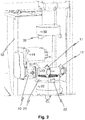
- the tool holder 10 is arranged outside the workpiece 21, but the chamfering cutter 11 or 11 'for chamfering the edge region is arranged in the region of the center opening of the workpiece 21 by means of the tool mandrel 13. As in particular from Fig. 2 can be seen, this extends the tool mandrel 13, starting from the arranged next to the workpiece holder 20 tool holder 10 over the annular toothed portion of the workpiece away in the region of the center opening of the workpiece, so that the Anfasfräser is arranged in this area and processed from there the edge.
- the Anfasfräser 11 is arranged for this purpose in an area above the central bore, the tool holder in an area next to and slightly above the workpiece holder 20. Since the teeth 12 of the Anfasfräsers 11 protrude beyond the radius of the tool mandrel 13, they can in the center bore of the workpiece 21 dive to edit the edges of the gearing.
- the workpiece 21 is directed with its bottom to the workpiece holder 20, while the edge of the toothing is toothed on the top by the Anfasfräser 11.
- the Anfasfräser engages from above into the center opening of the workpiece 21.
- the tool mandrel 13 extends above the top of the workpiece 21 over the annular region of the workpiece.
- the tool holder 10 is disposed on a machining head 40 and can be moved over the machine axes relative to the workpiece holder 20.
- the machining head 40 is arranged on a machine stand 55 in the exemplary embodiment.
- This machine stand 55 is arranged within a frame 50, which is provided next to the workpiece holder 20 on a common console 60 with which the unit is mounted on the machine bed.
- the machine axes for moving the machining head 40 comprise an X3 axis, with which the machining head can be moved in a direction perpendicular to the rotational axis C3 of the workpiece holder 20 and to the rotational axis B3 of the tool holder 10, and a Z3 axis, via which the machining head in a direction parallel to the axis of rotation C3 of the workpiece holder 20 can be moved.
- a pivot axis A3 is provided, via which the machining head about an axis which is perpendicular to the axes of rotation B3 and C3 of the tool holder 10 and the workpiece holder 20, can be pivoted.
- a shift axis V3 is provided, which allows a displacement of the tool holder 10 in the direction of its axis of rotation B3.
- a Y3 axis would also be conceivable over which the machining head 40 can be moved in a direction perpendicular to the X3 axis and to the Z3 axis.
- the axes X3, Z3 and V3 are preferably linear axes, which can be realized, for example, via slides.
- the tool holder 10 is arranged together with its drive 14 on the machining head 40.
- the arrangement is such that the axis of rotation B3 of the tool holder extends at a distance from the workpiece facing front side of the machine stand 55, in a plane which is perpendicular to the X3 axis.
- Such an embodiment of the machining head and the workpiece holder is also common in machining heads for externally toothed workpieces.
- the engagement with the workpiece does not take place on the side of the chamfer cutter facing away from the machine stand 55, but on the side of the chamfer cutter facing the machine stand 55.
- the annular region of the workpiece 21 to be machined must extend in the radial direction with respect to the axis of rotation C3 of the workpiece holder on the side of the chamfer cutter 11 facing the machine frame 55.
- the annular region of the workpiece 21 to be machined may extend between a front side of the machine stand 55 facing the workpiece and the chamfering cutter.
- the mandrel 13 can also be made so long that the Anfasfräser 11 and 11 'in the direction of the V3 axis in front of a side surface of the machine stand 55 is. As a result, the annular region of the workpiece 21 to be machined can extend next to the machine stand 55.
- the device according to the invention preferably has a sensor (not shown in the exemplary embodiment) for threading and / or centering the chamfer cutter into the internal toothing of the workpiece. It is preferably a non-contact sensor. For example, an inductive sensor and / or an optical sensor can be used.
- the sensor for threading and / or centering the Anfasfräsers is preferably arranged on a separate arm, via which it can be moved into the internal toothing of the recorded in the workpiece holder 20 workpiece 21 into it.
- the arm for the sensor on the machining head 40 and / or the machine stand 55 of the device is arranged and can be moved over the machine axes.
- the above-described embodiment of the present invention according to the first aspect is initially only for processing the edge on a first end side of the recorded in the workpiece holder 20 workpiece, on the side facing away from the workpiece holder 20 end face, in the embodiment of the top.
- the second aspect can be realized independently of the first aspect.
- the device according to the invention comprises, in addition to the first workpiece holder 20, a second workpiece holder 30 in order to be able to machine the edges of the toothing both on the upper side and on the lower side of the workpiece.
- the edge of the toothing on the top of the workpiece 21 is chamfered while this in the first workpiece holder 20 is received, and the edge of the toothing on the underside of the workpiece 21 anfasverierebearbeitet while this is arranged in the second workpiece holder 30. Accordingly, the workpiece 21 is received in the first workpiece holder 20, that its underside is directed to the workpiece holder 20, while the top is freely accessible, and so received in the second workpiece holder 30 that its top is directed to the second workpiece holder 30 and the bottom is freely accessible.
- the two workpiece holders are arranged opposite one another, so that one processing head is sufficient to machine both a workpiece which is received in the first workpiece holder 20 and a workpiece which is received in the second workpiece holder 30.
- the workpiece After machining the edge of the toothing on one side of the toothing, the workpiece is changed from one workpiece holder to the other workpiece holder. Which page is edited first, can be chosen arbitrarily.
- the axes of rotation C3 and C4 of the first and the second workpiece holder 20 and 30 are arranged in parallel and aligned with each other.
- the change of the workpiece from one workpiece holder to the other workpiece holder is in the in Fig. 1 to 6 illustrated embodiment realized in that the second workpiece holder 30 via a traverse Z4, which runs parallel to its axis of rotation C4, is movable.
- the second workpiece holder 30 can be placed on a recorded in the first workpiece holder 20 workpiece 21 be to grab this and lift from the first workpiece holder 20.
- the workpiece holders 20 and 30 have clamping jaws 22 and 32 for this purpose, which can act simultaneously on the workpiece 21. After the second workpiece holder 30 has been lowered onto the workpiece 21 and the workpiece has been secured on the second workpiece holder 30 via the clamping jaws 32, therefore, the clamping jaws 22 of the first workpiece holder 20 are loosened to release the workpiece 21.
- the position of the toothing of the workpiece 21 received in the second workpiece holder relative to the second workpiece holder 30 is preferably calculated from the known position of the toothing of the workpiece 21 relative to the first workpiece holder 20 and the relative position between the first and the second workpiece holder 20 and 30 during the transfer , A sensor for threading and / or centering the Anfasfräsers in the toothing of the second workpiece holder 30 received workpiece 21 is therefore not necessary.
- the Z4-axis is realized in the embodiment via a carriage 70 which is movable on a guide 80 and the second workpiece holder 30 carries.
- the device according to the invention is designed such that a workpiece received in the first or second workpiece holder is processed in each case according to the first aspect of the toothing.
- Anfasfräser is arranged over the tool mandrel in the region of the center opening of the workpiece, wherein the mandrel above or below the workpiece from an outer region to the inner region of the workpiece.
- a workpiece 21 is received in the workpiece holder 20, while the Anfasfräser 11 and 11 'are arranged together with the tool holder 10 next to the workpiece holder 20 or so far above the workpiece holder 20 that they do not form interference edges for changing the workpiece.
- the chamfering cutter 11 is then brought into engagement with the edge portion of the internal teeth on the upper side of the workpiece 21 received in the workpiece holder 20 by moving the X3 and / or Z3 axis. If the chamfering cutter 11 has previously been arranged next to the workpiece holder 20, the entire processing head is moved toward the workpiece holder 20 via the X3 axis until the chamfering cutter 11 is above the center opening of the internally toothed workpiece 21. Then, the chamfering cutter is brought into engagement with the edge by lowering the machining head via the Z3 axis to work it in the toothed manner. Was the chamfer 11 already above the workpiece holder 20, it only requires the lowering of the Z3 axis.
- the A3 axis and the V3 axis may be used to adjust the exact position of the chamfer cutter relative to the workpiece 21.
- the machining head After chamfering the edge of the gearing on top of the workpiece, the machining head is raised above the Z3 axis so that the chamfering mill 11 is moved out of the center opening of the gear and then by moving the machining head about the X3 or V3 axis moved next to the workpiece holder 20.
- the second workpiece holder 30 is lowered to take over the workpiece 21.
- chamfering of the edge of the toothing on the underside of the workpiece 21, as shown in FIG Fig. 4 and 5 is shown in more detail.
- the chamfering machining is done here in the same way according to the first aspect of the present invention as previously described with regard to the chamfering of the edge on the top of the workpiece described opposite direction of rotation.
- the position of the machining head with respect to the greater distance of Anfasfräsers 11 'to the tool holder 10 will be adjusted accordingly, in particular by methods on the V3 axis.
- a Chamfer-cut milling cutter is preferably designed as a chamfering cutter in the context of the present invention.
- a chamfer-cut cutter is a disc-shaped deburring tool 11 which Having cutting teeth 12 and Spahnnuten at the periphery, preferably with the same circumferential distance.
- the profile of the cutting teeth 12 of the Chamfer-Cut milling cutter is designed specifically for chamfering the edge of an internal toothing.
- the cutting teeth have a helical course in the circumferential direction.
- the Chamfer-Cut-cutter is multi-functional, with one tooth per gear.
- the formed on the front in the direction of rotation of the teeth cutting edges are on a common circle.
- the rotational movement between the Chamfer-Cut cutter and the workpiece is synchronized so that in each case a tooth coincides with a tooth gap of the workpiece.
- the chamfer-cut cutter 11 For chamfering the chamfer-cut cutter 11 is brought into a position as in Fig. 5 is reproduced. During the machining of the end edges of the tooth grooves, the workpiece 21 and the chamfer-cut milling cutter 11 rotate in a predetermined speed ratio, so that in each case a cutting tooth 12 processes the end edges of a toothed groove. It is understood that the chamfer-cut milling cutter 11 and the teeth 12 are designed according to the parameters of the toothing of the workpiece 21, so that the desired engagement with the front edges of the tooth grooves can take place.
- the device according to the invention preferably has a control by which the axes of rotation of the tool holder and the workpiece holder as well as the machine axes for adjusting the relative position between the tool holder and the workpiece holder are controlled.
- the controller preferably controls the device according to the invention automatically. In particular, she is there Programmed so that the methods described above or methods of use of the device according to the invention are carried out automatically.
- the inventive device for chamfering workpieces can be used in a machining center in combination with a gear cutting machine, which previously generates the toothing on the workpiece.
- the gear cutting machine can be, for example, a gear cutting machine for machining internal gears or a gear shaping machine or a skiving machine, which are particularly suitable for producing internal gears.
- the gear cutting machine and the device according to the invention may each have separate workpiece holders, wherein a workpiece changer is provided in order to transport the workpieces from the gear cutting machine to the chamfering device according to the invention.
- the workpieces can remain clamped on a workpiece holder and transported on the workpiece holder from the gear cutting machine to the device according to the invention.
- Fig. 6 an embodiment of a gear center is shown, which comprises a device 1 according to the invention according to the embodiment described in more detail above.
- the workpiece holder 20 is fixedly assigned in the embodiment of the device according to the invention, and is fitted via a ring loader 3 with workpieces.
- gear cutting machine is arranged at a different angular position 2, for example at an angle of 90 ° to the device 1 according to the invention, relative to the ring loader 3.
- the ring loader 3 can therefore transport toothed workpieces to the device according to the invention in the gear cutting machine.
- the workpieces can also be transported back to the gear cutting machine, for example, to allow chamfering between a roughing step and a finishing step.
- the rail 80 via which the Z4-axis is provided for moving the second workpiece holder 30, is arranged in the exemplary embodiment on a machine stand, which also carries the ring loader 3.
- the machining head 40 is arranged in a position opposite to the ring loader.
Abstract
Die vorliegende Erfindung betrifft eine Vorrichtung zum Anfasen mindestens einer stirnseitigen Kante der Verzahnung eines innenverzahnten Werkstücks mit mindestens einer drehbar gelagerten Werkstückaufnahme zur Aufnahme des Werkstücks und mit mindestens einer drehbar gelagerten Werkzeugaufnahme zur Aufnahme mindestens eines Anfasfräsers, insbesondere eines Chamfer-Cut-Fräsers, wobei die Werkzeugaufnahme neben einem in der Werkstückaufnahme aufgenommenen Werkstück angeordnet und/oder anordenbar ist und ein in der Werkzeugaufnahme aufgenommener Anfasfräser mittels eines Werkzeugdorns im Bereich der durch die Innenverzahnung gebildeten Mittenöffnung des Werkstücks anordenbar ist, um mit einer Kante der Innenverzahnung auf der Oberseite und/oder Unterseite des Werkstücks in Eingriff gebracht zu werden.The present invention relates to a device for chamfering at least one front edge of the teeth of an internally toothed workpiece with at least one rotatably mounted workpiece holder for receiving the workpiece and at least one rotatably mounted tool holder for receiving at least one Anfasfräsers, in particular a Chamfer-cut router, wherein the Tool holder is arranged adjacent to a recorded in the workpiece holder workpiece and / or can be arranged and an included in the tool holder Anfasfräser by means of a tool mandrel in the region formed by the internal teeth center opening of the workpiece can be arranged with an edge of the internal teeth on the top and / or bottom of the workpiece to be engaged.
Description
Die vorliegende Erfindung betrifft eine Vorrichtung und ein Verfahren zum Anfasen mindestens einer stirnseitigen Kante der Verzahnung eines innenverzahnten Werkstücks, mit mindestens einer drehbar gelagerten Werkstückaufnahme zur Aufnahme des Werkstücks und mit mindestens einer drehbar gelagerten Werkzeugaufnahme zur Aufnahme mindestens eines Anfasfräsers. Insbesondere kann es sich bei dem Anfasfräser um einen Chamfer-Cut-Fräser handeln.The present invention relates to an apparatus and a method for chamfering at least one end edge of the toothing of an internally toothed workpiece, with at least one rotatably mounted workpiece holder for receiving the workpiece and at least one rotatably mounted tool holder for receiving at least one Anfasfräsers. In particular, the chamfer cutter may be a chamfer-cut cutter.
Bei der Bearbeitung von Werkstücken zur Herstellung einer Verzahnung auf dem Werkstückrohling entstehen scharfkantige Materialüberstände an den bearbeiteten Werkstückkanten. Diese als Grate bezeichneten Überstände müssen durch Entgraten der Kanten der Verzahnung entfernt werden, da sie in den Folgeprozessen stören bzw. beim manuellen Teilhandling für den Maschinenbediener eine Verletzungsgefahr darstellen. Zusätzlich werden die Kanten der Verzahnung häufig noch mit speziellen Schutzanfasungen versehen.When machining workpieces to produce a toothing on the workpiece blank, sharp-edged material protrusions are created on the machined workpiece edges. These protrusions, called burrs, must be removed by deburring the edges of the toothing, since they interfere with the subsequent processes or represent a risk of injury during manual partial handling for the machine operator. In addition, the edges of the teeth are often still provided with special protective chamfers.
Das Anfasen der Werkstücke erfolgt üblicherweise durch speziell angepasste Entgrat-Werkzeuge im Anschluss an die Herstellung der Verzahnung auf dem Werkstückrohling. Für diesen Anfasprozess gibt es mehrere Verfahren nach dem Stand der Technik. In der Serienfertigung werden vor allem die Verfahren Drückentgraten gemäß der
Die
Die oben genannten Anfas-Verfahren werden üblicherweise zum Anfasen von Werkstücken mit einer Außenverzahnung eingesetzt, beispielsweise indem das Entgrat-Werkzeug zusammen mit dem Fräswerkzeug auf dem gleichen Werkzeugdorn aufgespannt und nach dem Fräsvorgang mit den Kanten der Verzahnung in Eingriff gebracht wird.The above chamfering methods are usually used for chamfering workpieces with external teeth, for example by the deburring tool is clamped together with the milling tool on the same mandrel and engaged after the milling operation with the edges of the toothing.
Aus der
Aufgabe der Erfindung ist es, eine verbesserte Vorrichtung und ein verbessertes Verfahren zum Anfasen der stirnseitigen Kanten der Verzahnung eines innenverzahnten Werkstücks zur Verfügung zu stellen.The object of the invention is to provide an improved apparatus and an improved method for chamfering the frontal edges of the toothing of an internally toothed workpiece.
Diese Aufgabe wird durch die Vorrichtungen und Verfahren gemäß den unabhängigen Ansprüchen der vorliegenden Anmeldung gelöst. Bevorzugte Ausgestaltungen der vorliegenden Erfindung sind Gegenstand der Unteransprüche.This object is achieved by the devices and methods according to the independent claims of the present application. Preferred embodiments of the present invention are the subject of the dependent claims.
In einem Aspekt umfasst die vorliegende Erfindung eine Vorrichtung zum Anfasen mindestens einer stirnseitigen Kante der Verzahnung eines innenverzahnten Werkstücks, wobei die Vorrichtung mindestens eine drehbar gelagerte Werkstückaufnahme zur Aufnahme des Werkstücks und mindestens eine drehbar gelagerte Werkzeugaufnahme zur Aufnahme eines Anfasfräsers, insbesondere eines Chamfer-Cut-Fräsers, aufweist. Erfindungsgemäß ist der erste Aspekt der vorliegenden Erfindung dadurch gekennzeichnet, dass die Werkzeugaufnahme neben einem in der Werkstückaufnahme aufgenommenen Werkstück angeordnet und/oder anordenbar ist, wobei ein in der Werkzeugaufnahme aufgenommener Anfasfräser mittels eines Werkzeugdorns in Bereich der durch die Innenverzahnung gebildeten Mittenöffnung des Werkstücks anordenbar ist, um mit einer Kante der Innenverzahnung auf der Oberseite und/oder Unterseite des Werkstücks in Eingriff gebracht zu werden.In one aspect, the present invention comprises a device for chamfering at least one end edge of the toothing of an internally toothed workpiece, wherein the device has at least one rotatably mounted workpiece holder for receiving the workpiece and at least one rotatably mounted tool holder for receiving a chamfer cutter, in particular a chamfer cutter. Milling cutter. According to the invention, the first aspect of the present invention is characterized in that the tool holder is arranged next to a workpiece received in the workpiece holder and / or can be arranged, wherein a chamfer cutter received in the tool holder can be arranged by means of a tool pin in the center opening of the workpiece formed by the internal toothing to be engaged with an edge of the internal teeth on the top and / or bottom of the workpiece.
Die Erfinder der vorliegenden Erfindung haben erkannt, dass es zum Anfasen einer Innenverzahnung nicht notwendig ist, die gesamte Vorrichtung, mit welcher das Anfasen erfolgt, innerhalb der durch die Innenverzahnung gebildeten Mittenöffnung anzuordnen. Weiterhin haben die Erfinder der vorliegenden Erfindung erkannt, dass es noch nicht einmal notwendig ist, die Werkzeugaufnahme in diesem Bereich anzuordnen.The inventors of the present invention have recognized that it is not necessary for chamfering an internal toothing to arrange the entire device with which the chamfering takes place within the central opening formed by the internal toothing. Furthermore, the inventors of the present invention have realized that it is not even necessary to arrange the tool holder in this area.
Vielmehr kann erfindungsgemäß die Werkzeugaufnahme neben dem Werkstück angeordnet werden, und lediglich der Anfasfräser mittels eines Werkzeugdorns im Innenbereich des Werkstücks angeordnet werden. Hierdurch ist es möglich, für die erfindungsgemäße Vorrichtung einen konventionell aufgebauten Fräskopf mit nur geringfügigen konstruktiven Änderungen einzusetzen. Da die Zähne des im Bereich der Mittenöffnung angeordneten Anfasfräsers über den Radius des Werkzeugdorns hinausragen, können diese in die Mittenbohrung des Werkstücks eintauchen, um die Kanten der Verzahnung zu bearbeiten, während der Werkzeugdorn oberhalb oder unterhalb des Werkstücks verläuft.Rather, according to the invention, the tool holder can be arranged next to the workpiece, and only the Anfasfräser be arranged by means of a tool mandrel in the inner region of the workpiece. This makes it possible to use a conventionally constructed milling head with only minor structural changes for the inventive device. Since the teeth of the chamfer cutter located in the region of the center opening project beyond the radius of the tool mandrel, they can dip into the center bore of the workpiece in order to machine the edges of the toothing while the tool mandrel runs above or below the workpiece.
Bevorzugt verläuft der Werkzeugdorn beim Anfasen einer Kante der Verzahnung ausgehend von der Werkzeugaufnahme an der Oberseite und/oder Unterseite des innenverzahnten Ringbereichs des Werkstücks vorbei von einem Außenbereich des Werkstücks zum Innenbereich des Werkstücks.Preferably, when chamfering an edge of the toothing, the tool mandrel runs from an outer region of the workpiece to the inner region of the workpiece, starting from the tool holder on the upper side and / or lower side of the internally toothed annular region of the workpiece.
Die vorliegende Erfindung erfordert hierbei lediglich einen relativ langen Werkzeugdorn, so dass sich dieser über den innenverzahnten Ringbereich des Werkstücks hinweg erstreckt, um den Anfasfräser im Innenbereich des Werkstücks anzuordnen.The present invention requires only a relatively long tool mandrel so that it extends beyond the internally toothed annular region of the workpiece in order to arrange the chamfer cutter in the inner region of the workpiece.
Bevorzugt beträgt die Länge des Werkzeugdorns von der Werkzeugaufnahme bis zu mindestens einem auf dem Werkzeugdorn angeordneten Anfasfräser mindestens 10% des Innenradius der Innenverzahnung des Werkstücks, bevorzugt mehr als 20% und mindestens 30%. In einer besonders bevorzugten Ausgestaltung beträgt die Länge mehr als 40%. Soweit mehrere Anfasfräser auf dem Werkzeugdorn vorgesehen sind, gelten diese Maßangaben bevorzugt für die Länge des Dorns zwischen der Werkzeugaufnahme und dem ersten, der Werkzeugaufnahme zugewandten Anfasfräser. Weiter bevorzugt beträgt auch die Länge des Dorns zwischen zwei auf dem Dorn angeordneten Anfasfräsern mindestens 10% des Innenradius der Innenverzahnung des Werkstücks, bevorzugt mehr als 20%, weiter bevorzugt mindestens 30% oder 40%.Preferably, the length of the tool mandrel from the tool holder to at least one chamfer cutter arranged on the tool mandrel is at least 10% of the inner radius of the internal toothing of the workpiece, preferably more than 20% and at least 30%. In a particularly preferred embodiment, the length is more than 40%. If several Anfasfräser are provided on the mandrel, these dimensions are preferred for the length of the mandrel between the tool holder and the first, the tool holder facing Anfasfräser. More preferably, the length of the mandrel between two chamfers arranged on the mandrel is at least 10% of the inner radius of the internal toothing of the workpiece, preferably more than 20%, more preferably at least 30% or 40%.
Die Werkzeugaufnahme kann in einer möglichen Ausführungsform an einem neben oder über der Werkstückaufnahme angeordneten Bearbeitungskopf angeordnet sein und über diesen relativ zur Werkstückaufnahme bewegt werden können. Besonders bevorzugt ist der Bearbeitungskopf an einen Maschinenständer neben oder über der Werkstückaufnahme angeordnet. Der Maschinenständer kann auf einem Maschinenbett angeordnet sein, welches auch die Werkstückaufnahme trägt.In one possible embodiment, the tool holder can be arranged on a machining head arranged next to or above the workpiece holder and can be moved relative thereto by means of the workpiece holder. Particularly preferably, the machining head is arranged on a machine stand next to or above the workpiece holder. The machine stand can be arranged on a machine bed, which also carries the workpiece holder.
Bevorzugt weist der Bearbeitungskopf eine Maschinenachse zur Bewegung der Werkzeugaufnahme in Achsrichtung der Werkstückaufnahme und/oder eine Maschinenachse zum Verfahren der Werkzeugaufnahme in eine Richtung senkrecht zur Drehachse der Werkstückaufnahme und/oder zu der Drehachse der Werkzeugaufnahme.Preferably, the machining head has a machine axis for moving the tool holder in the axial direction of the workpiece holder and / or a machine axis for moving the tool holder in a direction perpendicular to the axis of rotation of the workpiece holder and / or to the axis of rotation of the tool holder.
Weiterhin kann der Bearbeitungskopf eine Schwenkachse zum Schwenken der Werkzeugaufnahme um eine zur Drehachse der Werkzeugaufnahme und/oder zur Drehachse der Werkstückaufnahme senkrechte Schwenkachse und/oder eine Maschinenachse zum Vershiften der Werkzeugaufnahme in Richtung ihrer Drehachse aufweisen.Furthermore, the machining head may have a pivot axis for pivoting the tool holder about a pivot axis perpendicular to the axis of rotation of the tool holder and / or to the axis of rotation of the workpiece holder and / or a machine axis for shifting the tool holder in the direction of its axis of rotation.
Bevorzugt ist der am Werkzeugdorn angeordnete Anfasfräser von einer Unterseite und/oder Oberseite aus zugänglich.Preferably, the chamfer cutter arranged on the tool mandrel is accessible from a lower side and / or upper side.
Spricht die vorliegende Anmeldung von einer Oberseite bzw. einer Unterseite des Werkstückes, bzw. einer Anordnung von Komponenten oberhalb, unterhalb oder neben dem Werkstück, so bedeutet dies nicht, dass die Werkstückaufnahme eine vertikale Drehachse aufweisen muss oder dass die Oberseite in vertikaler Richtung oberhalb der Unterseite angeordnet ist, oder dass eine entsprechende Anordnung der Komponenten tatsächlich in vertikaler Richtung über oder unter dem Werkstück oder in horizontaler Richtung neben dem Werkstück erfolgt.Does the present application of an upper side or a lower side of the workpiece, or an arrangement of components above, below or next to the workpiece, this does not mean that the workpiece holder must have a vertical axis of rotation or that the top in the vertical direction above the Bottom is arranged, or that a corresponding arrangement of the components actually takes place in a vertical direction above or below the workpiece or in the horizontal direction next to the workpiece.
Vielmehr handelt es sich bei diesen Begriffen lediglich um die Angabe von relativen Anordnungen in einer durch die Werkstückdrehachse vorgegebenen Richtung, durch welche die Oberseite und die Unterseite des Werkstücks definiert ist. Welche Seite dabei als Oberseite des Werkstücks und welche als Unterseite angesehen wird, ist dabei im Rahmen der vorliegenden Erfindung unerheblich.Rather, these terms are merely the indication of relative arrangements in a direction predetermined by the workpiece axis of rotation, by which the top and the bottom of the workpiece is defined. Which side is considered as the top of the workpiece and which as the bottom, is irrelevant in the context of the present invention.
Je nach Maschinenkonzept wäre bspw. auch eine Anordnung denkbar, bei der die Werkstückachse während der Bearbeitung horizontal angeordnet ist, was wiederum eine horizontale Ausrichtung der erfindungsgemäßen Vorrichtung erfordern würde.Depending on the machine concept, an arrangement would also be conceivable, for example, in which the workpiece axis is arranged horizontally during processing, which in turn would require a horizontal alignment of the device according to the invention.
Alternativ oder zusätzlich kann die Werkzeugaufnahme über einen Bearbeitungskopf an einem Maschinenständer angeordnet sein, wobei sich der Bearbeitungskopf bevorzugt senkrecht zur Drehachse der Werkstückaufnahme und/oder zur Drehachse der Werkzeugaufnahme den dem Maschinenständer weg erstreckt. Insbesondere erstreckt sich hierdurch die Drehachse der Werkzeugaufnahme in einem gewissen Abstand zu dem Maschinenständer.Alternatively or additionally, the tool holder can be arranged on a machine stand via a machining head, the machining head preferably extending perpendicular to the axis of rotation of the workpiece holder and / or the axis of rotation of the tool holder extending away from the machine frame. In particular, this extends the axis of rotation of the tool holder at a certain distance from the machine frame.
Weiterhin alternativ oder zusätzlich kann die Werkzeugaufnahme so an einem Bearbeitungskopf angeordnet sein, dass sie sich parallel zur der der Werkstückaufnahme zugewandten Vorderseite des Maschinenständers erstreckt.As an alternative or in addition, the tool holder can be arranged on a machining head in such a way that it extends parallel to the front of the machine stand facing the workpiece holder.
Insbesondere kann die erfindungsgemäße Vorrichtung so aufgebaut sein, dass sich der Ringbereich des innenverzahnten Werkstücks, welcher durch den Anfasfräser angefast wird, in einem Bereich zwischen dem Maschinenständer und der Drehachse der Werkzeugaufnahme unterhalb oder oberhalb des Werkzeugdorns erstreckt.In particular, the device according to the invention can be constructed such that the annular region of the internally toothed workpiece, which is chamfered by the chamfering cutter, extends in a region between the machine stand and the axis of rotation of the tool holder below or above the tool mandrel.
In einer bevorzugten Ausgestaltung der vorliegenden Erfindung weist die erfindungsgemäße Vorrichtung einen Sensor zum Einfädeln und/oder Einmitten des Anfasfräsers in die Innenverzahnung des Werkstücks auf.In a preferred embodiment of the present invention, the device according to the invention has a sensor for threading and / or centering the Anfasfräsers in the internal toothing of the workpiece.
Ein solcher Sensor ist insbesondere dann notwendig, wenn die erfindungsgemäße Vorrichtung als stand-alone Anordnung ausgeführt ist bzw. das Werkstück, dessen Kanten angefast werden sollen, zuvor bei der Herstellung der Verzahnung in einer anderen Werkstückaufnahme angeordnet war und bspw. über einen Werkstückwechsler zur Werkstückaufnahme der erfindungsgemäßen Vorrichtung transportiert wird, da in diesem Fall die Position der Verzahnung relativ zur Vorrichtung nicht bekannt ist.Such a sensor is particularly necessary when the device according to the invention is designed as a stand-alone arrangement or the workpiece whose edges are to be chamfered, previously in the manufacture of the toothing in one Another workpiece holder was arranged and, for example, is transported via a workpiece changer for workpiece holder of the device according to the invention, since in this case the position of the toothing is not known relative to the device.
Bevorzugt handelt es sich um einen berührungslosen Sensor. Beispielsweise kann ein induktiver Sensor und/oder ein optischer Sensor eingesetzt werden.It is preferably a non-contact sensor. For example, an inductive sensor and / or an optical sensor can be used.
Der Sensor zum Einfädeln und/oder Einmitten des Anfasfräsers wird vorzugsweise an einem separaten Arm geordnet, über welchen er in die Innenverzahnung hinein verfahren wird. Bevorzugt ist der Arm für den Sensor zusammen mit der Werkzeugaufnahme an einem Bearbeitungskopf der Vorrichtung angeordnet und/oder kann über die selben Maschinenachsen verfahren werden. Weiterhin wäre beispielsweise beim Einsatz optischer Sensoren auch eine Anordnung des Sensors außerhalb der Verzahnung denkbar.The sensor for threading and / or centering the Anfasfräsers is preferably arranged on a separate arm, via which it is moved into the internal toothing. Preferably, the arm for the sensor is arranged together with the tool holder on a machining head of the device and / or can be moved over the same machine axes. Furthermore, an arrangement of the sensor outside the toothing would be conceivable, for example, when using optical sensors.
In einem zweiten Aspekt umfasst die vorliegende Erfindung eine Vorrichtung zum Anfasen mindestens einer stirnseitigen Kante der Verzahnung eines innenverzahnten Werkstücks, wobei die Vorrichtung eine erste drehbar gelagerte Werkstückaufnahme zur Aufnahme des Werkstücks und mindestens eine drehbar gelagerte Werkzeugaufnahme zur Aufnahme mindestens eines Anfasfräsers, insbesondere eines Chamfer-Cut-Fräsers, aufweist. Der zweite Aspekt der vorliegenden Erfindung ist dadurch gekennzeichnet, dass die Vorrichtung eine zweite drehbar gelagerte Werkstückaufnahme zur Aufnahme des Werkstücks aufweist. Dabei ist die Kante der Verzahnung auf einer ersten Stirnseite des Werkzeugs anfasbearbeitbar, während das Werkstück in der ersten Werkstückaufnahme aufgenommen ist, und die Kante auf der zweiten Stirnseite des Werkstücks anfasbearbeitbar, während das Werkstück in der zweiten Werkstückaufnahme aufgenommen ist.In a second aspect, the present invention comprises a device for chamfering at least one front edge of the toothing of an internally toothed workpiece, the device having a first rotatably mounted workpiece holder for receiving the workpiece and at least one rotatably mounted tool holder for receiving at least one chamfer cutter, in particular a chamfer cutter. Cut router, has. The second aspect of the present invention is characterized in that the device has a second rotatably mounted workpiece holder for receiving the workpiece. In this case, the edge of the toothing on a first end side of the tool is anfasbearbeitbar while the workpiece is received in the first workpiece holder, and the edge on the second end face of the workpiece anfasbearbeitbar while the workpiece is received in the second workpiece holder.
Die Erfinder der vorliegenden Erfindung haben erkannt, dass die Anfasbearbeitung der Kanten der Verzahnung sowohl auf der Oberseite als auch auf der Unterseite eines in einer Werkstückaufnahme aufgenommen, innenverzahnten Werkstücks besonders kompliziert ist, da insbesondere die Kante der Verzahnung auf der der Werkzeugaufnahme zugewandten Seite des Werkstückes äußerst schlecht zugänglich ist.The inventors of the present invention have recognized that the chamfering of the edges of the toothing on both the top and on the bottom of a received in a workpiece holder, internally toothed workpiece is particularly complicated, since in particular the edge of the toothing on the tool holder facing side of the workpiece is extremely difficult to access.
Gemäß dem zweiten Aspekt der vorliegenden Erfindung wird dieses Problem dadurch gelöst, dass zwei Werkstückaufnahmen vorgesehen sind, so dass jeweils die Kante anfasbearbeitet werden kann, welche auf der der Werkstückaufnahme abgewandten Seite angeordnet ist und daher leicht zugänglich ist.According to the second aspect of the present invention, this problem is solved in that two workpiece holders are provided, so that in each case the edge can be chamfered, which is arranged on the side facing away from the workpiece holder and therefore easily accessible.
Bevorzugt weist die erfindungsgemäße Vorrichtung gemäß dem zweiten Aspekt einen über Maschinenachsen verfahrbaren Bearbeitungskopf auf, welcher zur Anfasbearbeitung der Kanten der Verzahnung sowohl auf der ersten, als auf der zweiten Stirnseite dient. Es kann daher der gleiche Bearbeitungskopf eingesetzt werden, um sowohl ein Werkstück, welches in der ersten Werkstückaufnahme aufgenommen ist, als auch ein Werkstück, welches in der zweiten Werkstückaufnahme aufgenommen ist, zu bearbeiten. Insbesondere können dabei die gleichen Maschinenachsen eingesetzt werden, um die Anfasbearbeitung durchzuführen.According to the second aspect, the device according to the invention preferably has a machining head which can be moved over machine axes and which serves for chamfering the edges of the toothing both on the first and on the second end face. Therefore, the same machining head can be used to machine both a workpiece received in the first workpiece holder and a workpiece received in the second workpiece holder. In particular, the same machine axes can be used to perform chamfering.
Bevorzugt ist die Werkzeugaufnahme der erfindungsgemäßen Vorrichtung an dem Bearbeitungskopf angeordnet und kann durch dessen Maschinenachsen verfahren werden.Preferably, the tool holder of the device according to the invention is arranged on the machining head and can be moved by its machine axes.
Alternativ oder zusätzlich kann die Anfasbearbeitung der Kanten der Verzahnung auf der ersten und der zweiten Stirnseite über denselben Anfasfräser oder über mehrere in derselben Werkzeugaufnahme aufgenommene Anfasfräser erfolgen. Besonders bevorzugt erfolgt die Anfasbearbeitung der Kanten der Verzahnung auf der ersten und zweiten Stirnseite des Werkstücks dabei über zwei separate, auf dem gleichen Werkzeugdorn aufgespannte Anfasfräser.Alternatively or additionally, the chamfering of the edges of the toothing on the first and the second end side can take place via the same chamfering cutter or via a plurality of chamfering cutters received in the same tool holder. Particularly preferably, the chamfering of the edges of the toothing takes place on the first and second end faces of the workpiece via two separate chamfered cutters mounted on the same tool mandrel.
Bevorzugt weist die erfindungsgemäße Vorrichtung eine Vorrichtung zum Wechseln des Werkstücks von der ersten Werkstückaufnahme zur zweiten Werkstückaufnahme und/oder von der zweiten Werkstückaufnahme zur ersten Werkstückaufnahme auf. Insbesondere kann daher das Werkstück, nachdem die Kanten der Verzahnung auf einer ersten Stirnseite bearbeitet wurden, während dieses in der ersten Werkstückaufnahme aufgenommen war, zur zweiten Werkstückaufnahme gewechselt werden, um die Kanten der Verzahnung auf der zweiten Stirnseite Anfaszubearbeiten.The device according to the invention preferably has a device for changing the workpiece from the first workpiece holder to the second workpiece holder and / or from the second workpiece holder to the first workpiece holder on. In particular, therefore, after the edges of the toothing have been machined on a first end side while it was received in the first workpiece fixture, the workpiece can be changed to the second workpiece fixture to chamfer the edges of the toothing on the second end face.
Bevorzugt erfolgt der Wechsel so, dass die zweite Stirnseite des Werkstücks der ersten Werkstückaufnahme zugewandt ist, während das Werkstück in dieser aufgenommen ist, und die erste Stirnseite des Werkstücks der zweiten Werkstückaufnahme zugewandt ist, während das Werkstück in dieser angeordnet ist, so dass die jeweils anderen Stirnseiten zugänglich sind und bearbeitet werden können.Preferably, the change takes place such that the second end face of the workpiece faces the first workpiece holder, while the workpiece is received therein, and the first end side of the workpiece faces the second workpiece holder, while the workpiece is arranged in this, so that the respective other end faces are accessible and can be edited.
In einer möglichen Ausführungsform der vorliegenden Erfindung kann die Vorrichtung zum Wechseln des Werkstücks dadurch zur Verfügung gestellt werden, dass eine der beiden Werkstückaufnahmen so verfahrbar ist, dass sie ein in der anderen Werkstückaufnahme aufgenommenes Werkstück greifen kann.In one possible embodiment of the present invention, the device for changing the workpiece can be made available in that one of the two workpiece holders is movable so that it can grip a workpiece received in the other workpiece holder.
Alternativ oder zusätzlich kann ein Werkstückwechsler zum Verfahren des Werkstücks von der einen Werkstückaufnahme zu der anderen Werkstückaufnahme vorgesehen sein.Alternatively or additionally, a workpiece changer may be provided for moving the workpiece from one workpiece holder to the other workpiece holder.
Bevorzugt wird die Drehposition des Werkstücks bei der Werkstückübergabe elektronisch von der ersten Werkstückaufnahme auf die zweite Werkstückaufnahme übertragen, so dass nach der Werkstückübergabe die Drehposition wieder bekannt ist. Insbesondere kann so ein erneuter Einfädelprozess nicht mehr erforderlich sein, um den Anfasfräser zum Anfasen der Verzahnung auf der zweiten Stirnseite des Werkstücks korrekt zu positionieren.Preferably, the rotational position of the workpiece in the workpiece transfer electronically transmitted from the first workpiece holder to the second workpiece holder, so that after the workpiece transfer, the rotational position is known again. In particular, such a renewed threading process may no longer be necessary to correctly position the chamfering tool for chamfering the toothing on the second end face of the workpiece.
In einer bevorzugten Ausgestaltung der vorliegenden Erfindung sind die beiden Werkstückaufnahmen auf zwei gegenüberliegenden Seiten eines Arbeitsbereiches angeordnet oder anordenbar. Bevorzugt ist das Werkstück je nachdem, in welcher Werkstückaufnahme es aufgenommen ist, mit seiner ersten oder zweiten Stirnseite dem Arbeitsbereich zugewandt. Bevorzugt sind oder werden der oder die Anfasfräser in dem Arbeitsbereich angeordnet, um die jeweiligen Kanten der Verzahnung auf den dem Arbeitsbereich zugewandten Stirnseiten zu bearbeiten.In a preferred embodiment of the present invention, the two workpiece holders are arranged on two opposite sides of a work area or can be arranged. Preferably, the workpiece is, depending on which workpiece holder it is received, with its first or second end face facing the work area. Preferably, the chamfering cutter or chisels are arranged in the working area in order to machine the respective edges of the toothing on the end faces facing the working area.
In einer möglichen Ausführungsform der vorliegenden Erfindung weisen die beiden Werkstückaufnahmen parallele Drehachsen auf. Besonders bevorzugt sind die beiden Werkstückaufnahme koaxial angeordnet. Besonders bevorzugt ist in diesem Fall die eine Werkstückaufnahme in Richtung ihrer Drehachse zur anderen Werkstückaufnahme verfahrbar, um das Werkstück zu übernehmen.In one possible embodiment of the present invention, the two workpiece holders have parallel axes of rotation. Particularly preferably, the two workpiece holder are arranged coaxially. In this case, the one workpiece holder is particularly preferably movable in the direction of its axis of rotation to the other workpiece holder in order to take over the workpiece.
Der erste und der zweite Aspekt der vorliegenden Erfindung sind zunächst unabhängig voneinander und können jeweils separat verwirklicht werden.The first and second aspects of the present invention are initially independent of each other and can each be implemented separately.
Besonders bevorzugt sind die beiden Aspekte der vorliegenden Erfindung jedoch in einer Vorrichtung kombiniert. Insbesondere kann die Anfasbearbeitung eines in der ersten und/oder zweiten Werkstückaufnahme einer Vorrichtung gemäß dem zweiten Aspekt der vorliegenden Erfindung aufgenommenen Werkstücks gemäß dem ersten Aspekt erfolgen.Most preferably, however, the two aspects of the present invention are combined in one device. In particular, the chamfering of a workpiece accommodated in the first and / or second workpiece holder of a device according to the second aspect of the present invention can be carried out according to the first aspect.
Besonders bevorzugt ist die Werkzeugaufnahme neben den beiden Werkstückaufnahmen angeordnet und/oder anordenbar, wobei mindestens ein Anfasfräser mittels eines Werkzeugdorns oberhalb der durch die Innenverzahnung gebildeten Mittenöffnung des Werkstücks anordenbar ist, wenn dieses in der ersten Werkstückaufnahme angeordnet ist, um mit einer Kante der Verzahnung auf der Oberseite des Werkstücks in Eingriff gebracht zu werden. Weiterhin kann ein Anfasfräser mittels eines Werkzeugdorns unterhalb der durch die Innenverzahnung gebildeten Mittenöffnung anordenbar sein, wenn dieses in der zweiten Werkstückaufnahme angeordnet ist, um mit einer Kante der Verzahnung auf der Unterseite des Werkstücks in Eingriff gebracht zu werden. Bevorzugt wird zur Anfasbearbeitung der Kanten der Verzahnung auf Oberseite und Unterseite die gleiche Werkzeugaufnahme eingesetzt.Particularly preferably, the tool holder is arranged next to the two workpiece holders and / or can be arranged, wherein at least one chamfer can be arranged by means of a tool mandrel above the center opening formed by the internal teeth of the workpiece, if this is arranged in the first workpiece holder, with an edge of the toothing on the top of the workpiece to be engaged. Furthermore, a chamfering cutter can be arranged by means of a tool mandrel below the central opening formed by the internal toothing, if this is arranged in the second workpiece holder, in order to be brought into engagement with an edge of the toothing on the underside of the workpiece. Preferably, the same tool holder is used for chamfering the edges of the toothing on top and bottom.
In einer ersten Alternative der vorliegenden Erfindung werden zum Bearbeiten der Kanten der Verzahnung auf der Oberseite und Unterseite separate, bevorzugt auf dem gleichen Werkzeugdorn angeordnete Anfasfräser eingesetzt.In a first alternative of the present invention, separate chamfering cutters, preferably arranged on the same tool mandrel, are used to machine the edges of the toothing on the upper side and lower side.
Besonders bevorzugt wird zum Bearbeiten der Kanten der Verzahnung auf der Oberseite und Unterseite mit entgegengesetzten Drehrichtungen der Werkzeugaufnahme gearbeitet, um die gleiche Schnittrichtung zwischen dem Werkzeug und dem Werkstück beim Anfasen der Kanten auf der Oberseite und der Unterseite zu erreichen. Insbesondere kann die Drehrichtung so gewählt werden, dass sowohl beim Anfasen der Kanten der Verzahnung auf der Oberseite, als auch beim Anfasen der Kanten der Verzahnung auf der Unterseite eine Bearbeitung von den Stirnseiten in die Verzahnung hinein erfolgt, oder die Drehrichtung wird so gewählt, dass jeweils eine Bearbeitung der Kanten der Verzahnung mit einer Schnittrichtung aus der Verzahnung in Richtung auf die Stirnseiten erfolgt. Dies hat den Vorteil, dass beim Anfasen verbleibende Grate entweder nur auf den Stirnseiten, oder nur innerhalb der Verzahnung verbleiben. Die Drehrichtung der jeweiligen Werkstückaufnahme wird entsprechend der Drehrichtung des Anfasfräsers angepasst.Particularly preferred for working the edges of the teeth on the top and bottom with opposite directions of rotation of the tool holder is worked to achieve the same cutting direction between the tool and the workpiece during chamfering the edges on the top and bottom. In particular, the direction of rotation can be chosen so that both the chamfering of the edges of the toothing on the top, as well as chamfering the edges of the teeth on the bottom of a processing from the end faces into the teeth takes place, or the direction of rotation is chosen so that in each case a processing of the edges of the toothing takes place with a cutting direction of the toothing in the direction of the end faces. This has the advantage that during chamfering remaining burrs remain either only on the end faces, or only within the toothing. The direction of rotation of the respective workpiece holder is adjusted according to the direction of rotation of the chamfer cutter.
Alternativ kann zum Bearbeitung der Kanten der Verzahnung auf Oberseite und Unterseite derselbe Anfasfräser eingesetzt werden. In einer ersten Alternative kann dieser im gleichen radialen Bereich des Werkstücks mit der Kante der Verzahnung auf Ober- und Unterseite in Eingriff gebracht werden. Dies hat jedoch den Nachteil, dass jeweils unterschiedliche Schnittrichtungen bei der Anfasbearbeitung der Kanten der Verzahnung auf Ober- und Unterseite bestehen.Alternatively, the same chamfer cutter can be used to machine the edges of the toothing on top and bottom. In a first alternative, it can be brought into engagement in the same radial region of the workpiece with the edge of the toothing on top and bottom sides. However, this has the disadvantage that in each case different cutting directions in the chamfering of the edges of the toothing on top and bottom exist.
Bevorzugt wird der Anfasfräser daher mit einer bezüglich der Drehachse des Werkstücks ersten radialen Richtung mit einem Kantenbereich der Verzahnung auf einer ersten Seite des Werkstücks in Eingriff gebracht und nach dem Wechsel des Werkstücks in die zweite Werkstückaufnahme durch Verfahren der Werkzeugaufnahme in einer bezüglich der Drehachse des Werkstücks zweiten radialen Richtung mit einem radial gegenüberliegenden Kantenbereich der Verzahnung auf der zweiten Seite des Werkstücks in Eingriff gebracht. Dies hat den Vorteil, dass sich wiederrum die gleiche Schnittrichtung bezüglich des Werkstücks auf beiden Seiten ergibt. Hierbei muss beim Wechsel der Eingriffsstellen die Drehrichtung der Werkstückaufnahmen angepasst werden.The chamfering cutter is therefore preferably brought into engagement with an edge region of the toothing on a first side of the workpiece with respect to the axis of rotation of the workpiece and after the workpiece has been changed into the second workpiece holder by moving the tool holder in a direction of rotation of the workpiece second radial direction with a radially opposite edge portion of the toothing on the second side of the workpiece engaged. This has the advantage that in turn results in the same cutting direction with respect to the workpiece on both sides. In this case, the direction of rotation of the workpiece holders must be adjusted when changing the intervention points.
Bevorzugt sind der oder die auf einem Werkzeugdorn angeordneten Anfasfräser von zwei Seiten aus zugänglich, um jeweils mit einer Kante des Werkstücks in Eingriff gebracht werden zu können. Insbesondere sind sie sowohl von der Oberseite, als auch von der Unterseite aus zugänglich.Preferably, the chamfer cutter or chisels arranged on a tool mandrel are accessible from two sides in order to be able to be engaged in each case with one edge of the workpiece. In particular, they are accessible both from the top, as well as from the bottom.
Die erfindungsgemäßen Vorrichtungen werden üblicherweise in der Serienfertigung und insbesondere der Großserienfertigung eingesetzt. Die Bearbeitung der Werkstücke und damit auch der Anfasprozess erfolgt in diesem Fall automatisiert durch die Steuerung der Vorrichtung.The devices according to the invention are usually used in mass production and in particular mass production. The machining of the workpieces and thus also the Anfasprozess takes place in this case automatically by the control of the device.
Die erfindungsgemäßen Vorrichtungen weisen daher bevorzugt eine Steuerung zur automatischen Ansteuerung der Maschinenachsen der Vorrichtung zum Anfasen der Kante der Verzahnung auf mindestens einer und bevorzugt auf beiden Stirnseiten eines Werkstücks auf.The devices according to the invention therefore preferably have a control for automatic control of the machine axes of the device for chamfering the edge of the toothing on at least one and preferably on both end faces of a workpiece.
Die Steuerung der Vorrichtung ist bevorzugt so programmiert, dass die erfindungsgemäßen Vorrichtungen die oben im Hinblick auf deren Funktionsweise und/oder Anwendung beschriebenen Schritte automatisch durchführt.The control of the device is preferably programmed such that the devices according to the invention automatically perform the steps described above with regard to their mode of operation and / or application.
Die Steuerung weist insbesondere einen Mikroprozessor und einen Speicher auf, in welchem ein Steuerprogramm zur Ansteuerung der Vorrichtung abgespeichert ist, welches durch den Mikroprozessor abgearbeitet wird.The controller has in particular a microprocessor and a memory in which a control program for controlling the device is stored, which is processed by the microprocessor.
Die vorliegende Erfindung stellt zunächst eine Vorrichtung, wie sie oben näher beschrieben wurde, unter Schutz, welche zur Aufnahme eines Anfasfräsers und insbesondere eines Chamfer-Cut-Fräsers in der Werkzeugaufnahme und zur Durchführung der oben beschriebenen Anwendungen geeignet ist.The present invention initially provides a device as described in more detail above, which is suitable for receiving a Anfasfräsers and in particular a Chamfer-Cut router in the tool holder and to carry out the applications described above.
Die vorliegende Erfindung umfasst jedoch ebenfalls eine Vorrichtung, wie sie oben beschrieben ist, bei welcher mindestens ein Anfasfräser in der Werkzeugaufnahme aufgenommen ist, bzw. bei welchem bei mehreren Werkzeugaufnahmen in diesen jeweils Anfasfräser aufgenommen sind. Insbesondere sind dabei in der Werkzeugaufnahme oder den Werkzeugaufnahmen Chamfer-Cut-Fräser aufgenommen.However, the present invention also includes a device, as described above, in which at least one chamfering cutter is received in the tool holder, or in which, in the case of a plurality of tool holders, chamfering tools are respectively accommodated therein. In particular, Chamfer cut milling cutters are accommodated in the tool holder or the tool holders.
Die vorliegende Erfindung betrifft weiterhin ein Verzahnbearbeitungszentrum mit einer Vorrichtung, wie sie oben beschrieben wurde, einer Verzahnmaschine und einem Werkstückwechsler. Bevorzugt handelt es sich bei der Verzahnmaschine um eine Maschine zur Bearbeitung von Innenverzahnungen, insbesondere eine Fräsmaschine oder eine Verzahnungsstoßmaschine oder um eine Wälzschälmaschine. Bevorzugt erfolgt die Verzahnbearbeitung und das Anfasen der Werkstücke in dem Verzahnbearbeitungszentrum taktzeit-parallel. Insbesondere werden durch die Verzahnmaschine verzahnte Werkstücke über den Werkstückwechsler zur Vorrichtung gemäß der vorliegenden Erfindung zum Anfasen weiter transportiert, um angefast zu werden, während auf der Verzahnmaschine bereits das nächste Werkstück verzahnt wird. Dabei ist auch ein Anfasen des Werkstücks zwischen einem Schruppschritt und einem Schlichtschritt denkbar, wofür das Werkstück bevorzugt von der Verzahnmaschine zu der erfindungsgemäßen Vorrichtung und wieder zurück verfahren wird.The present invention further relates to a gear machining center having a device as described above, a gear cutting machine and a workpiece changer. The gear cutting machine is preferably a machine for machining internal gears, in particular a milling machine or a gear cutting machine or a skiving machine. Preferably, the gear processing and the chamfering of the workpieces in the Verzahnbearbeitungszentrum clock time-parallel. In particular, workpieces toothed by the gear cutting machine are further transported via the workpiece changer to the apparatus according to the present invention for chamfering in order to be chamfered while the next workpiece is already being toothed on the gear cutting machine. In this case, chamfering of the workpiece between a roughing step and a finishing step is conceivable, for which the workpiece is preferably moved from the gear cutting machine to the device according to the invention and back again.
Bevorzugt handelt es sich bei dem Werkstückwechsler um eine Ring-Automation, wobei weiterhin bevorzugt die erfindungsgemäße Vorrichtung zum Anfasen sowie die Verzahnmaschine an unterschiedlichen Winkelpositionen der Ring-Automation angeordnet sind.Preferably, the workpiece changer is a ring automation, wherein furthermore preferably the chamfering device according to the invention and the gear cutting machine are arranged at different angular positions of the ring automation.
Bevorzugt weisen die Verzahnmaschine und die erfindungsgemäße Vorrichtung separate Werkstückaufnahmen auf. Der Werkstückwechsler wechselt in diesem Fall ein Werkstück nach der Verzahnbearbeitung der Verzahnmaschine von der dortigen Werkstückaufnahme zur Werkstückaufnahme der erfindungsgemäßen Vorrichtung zum Anfasen.The gear cutting machine and the device according to the invention preferably have separate workpiece holders. The workpiece changer changes in this case, a workpiece after the gear processing of the gear cutting machine from the local workpiece holder for workpiece holder of the inventive device for chamfering.
In einer alternativen Ausgestaltung kann das Verzahnbearbeitungszentrum jedoch auch mehrere Werkstückaufnahmen aufweisen, in welchen die Werkstücke für die Verzahnbearbeitung und die Anfasbearbeitung verbleiben. In diesem Fall werden die Werkstückaufnahmen bevorzugt von der Verzahnmaschine zu der erfindungsgemäßen Vorrichtung bewegt und/oder umgekehrt.In an alternative embodiment, however, the gear machining center may also have a plurality of workpiece holders, in which the workpieces for the gear processing and chamfering remain. In this case, the workpiece holders are preferably moved from the gear cutting machine to the device according to the invention and / or vice versa.
Der Werkstückwechsler wird bevorzugt dazu eingesetzt, um Werkstücke von einer externen Transportstrecke oder anderen Bearbeitungsstationen auf die Werkstückaufnahme oder Werkstückaufnahmen aufzulegen und von diesen abzunehmen.The workpiece changer is preferably used to place workpieces from an external transport path or other processing stations on the workpiece holder or workpiece holders and remove them.
Gemäß einem weiteren Aspekt der vorliegenden Erfindung kann die erfindungsgemäße Vorrichtung auch als eine separate Maschine ausgeführt sein. Bevorzugt erhält diese verzahnte Werkstücke von einer Transportstrecke und/oder Automation, um diese Anfaszubearbeiten. Die entsprechend bearbeiteten Werkstücke werden dann bevorzugt wieder einer Transportstrecke und/oder Automation übergeben.According to a further aspect of the present invention, the device according to the invention can also be designed as a separate machine. Preferably, this toothed workpieces receives from a transport route and / or automation to this Anfaszubearbeiten. The correspondingly machined workpieces are then preferably transferred back to a transport line and / or automation.
Die vorliegende Erfindung umfasst neben den erfindungsgemä0en Vorrichtungen auch entsprechende Verfahren. Insbesondere umfasst die vorliegende Erfindung auch jene Verfahren, welche jeweils oben im Hinblick auf die erfindungsgemäßen Vorrichtungen beschrieben wurden.The present invention also includes corresponding methods in addition to the devices according to the invention. In particular, the present invention also encompasses those methods which have been described above with respect to the devices according to the invention.
Auch unabhängig hiervon umfasst die vorliegende Erfindung in Ausprägung des ersten Aspektes ein Verfahren zum Anfasen mindestens einer stirnseitigen Kante der Verzahnung eines innenverzahnten Werkstücks durch einen in einer drehbar gelagerten Werkzeugaufnahme aufgenommenen Anfasfräser, insbesondere einen Chamfer-Cut-Fräser. Das erfindungsgemäße Verfahren ist dadurch gekennzeichnet, dass die Werkzeugaufnahme neben einem in einer Werkstückaufnahme aufgenommenen Werkstück angeordnet wird und der in der Werkzeugaufnahme aufgenommene Anfasfräser über einen Werkzeugdorn im Bereich der durch die Innenverzahnung gebildeten Mittenöffnung angeordnet wird, um mit einer Kante der Verzahnung auf der Oberseite und/oder Unterseite des Werkstücks in Eingriff gebracht zu werden.Also independently of this, the present invention in the form of the first aspect comprises a method for chamfering at least one end edge of the toothing of an internally toothed workpiece by a chamfer-cut milling cutter, in particular a chamfer-cut milling cutter, received in a rotatably mounted tool holder. The method according to the invention is characterized in that the tool holder is arranged next to a workpiece accommodated in a workpiece holder and the chamfer cutter received in the tool holder is arranged via a tool mandrel in the center opening formed by the internal toothing, with an edge of the toothing on the upper side and / or underside of the workpiece to be engaged.
Bevorzugt erfolgt das erfindungsgemäße Verfahren so, wie dies bereits oben im Hinblick auf die Vorrichtung gemäß dem ersten Aspekt der vorliegenden Erfindung näher dargestellt wurde. Insbesondere kann das erfindungsgemäße Verfahren unter Verwendung einer solchen Vorrichtung durchgeführt werden.The method according to the invention preferably takes place as has already been described in more detail above with regard to the device according to the first aspect of the present invention. In particular, the method according to the invention can be carried out using such a device.
Gemäß dem zweiten Aspekt umfasst die vorliegende Erfindung weiterhin ein Verfahren zum Anfasen mindestens einer stirnseitigen Kante der Verzahnung eines innenverzahnten Werkstücks durch einen in einer drehbar gelagerten Werkzeugaufnahme aufgenommenen Anfasfräser, insbesondere einen Chamfer-Cut-Fräser. Gemäß dem zweiten Aspekt ist vorgesehen, dass die Kante der Verzahnung auf einer ersten Stirnseite des Werkstücks anfasbearbeitet wird, während das Werkstück in einer ersten Werkstückaufnahme aufgenommen ist, und die Kante der Verzahnung auf einer zweiten Stirnseite des Werkstücks anfasbearbeitet wird, während das Werkstück in einer zweiten Werkstückaufnahme aufgenommen ist.According to the second aspect, the present invention further comprises a method for chamfering at least one frontal edge of the toothing of an internally toothed workpiece by a chamfer cutters, in particular a chamfer-cut milling cutter, received in a rotatably mounted tool holder. According to the second aspect, it is provided that the edge of the toothing on a first end side of the workpiece is machined while the workpiece is received in a first workpiece holder, and the edge of the toothing on a second end face of the workpiece is machined while the workpiece in a second workpiece holder is added.
Bevorzugt erfolgt auch dieses Verfahren so, wie oben bereits im Hinblick auf die erfindungsgemäße Vorrichtung gemäß dem zweiten Aspekt näher dargestellt wurde. Besonders bevorzugt erfolgt das Verfahren unter Verwendung einer solchen Vorrichtung.Preferably, this method also takes place as already described in more detail above with regard to the device according to the invention according to the second aspect. Particularly preferably, the method is carried out using such a device.
Besonders bevorzugt werden die Verfahren gemäß dem ersten und dem zweiten Aspekt der vorliegenden Erfindung kombiniert angewandt.Most preferably, the methods according to the first and second aspects of the present invention are used in combination.
Die vorliegende Erfindung umfasst weiterhin die Verwendung eines Anfasfräsers, insbesondere die Verwendung eines Chamfer-Cut-Fräsers, zur Durchführung eines der erfindungsgemäßen Verfahren, wie sie oben dargestellt wurden.The present invention further includes the use of a chamfering cutter, in particular the use of a chamfer-cut milling cutter, for carrying out one of the methods according to the invention, as described above.
Weiterhin umfasst die vorliegende Erfindung die Verwendung eines Anfasfräsers, insbesondere eines Chamfer-Cut-Fräsers, in einer der erfindungsgemäßen Vorrichtungen, wie sie oben beschrieben wurden.Furthermore, the present invention comprises the use of a chamfering cutter, in particular a chamfer-cut milling cutter, in one of the devices according to the invention, as described above.
Die erfindungsgemäßen Verfahren und Vorrichtungen werden bevorzugt zum Anfasen der Kanten von Stirnradverzahnungen eingesetzt.The methods and devices according to the invention are preferably used for chamfering the edges of spur gears.
Bei den erfindungsgemäßen Werkstücken handelt es sich bevorzugt um Zahnräder, insbesondere um Zahnräder mit einer Innenverzahnung. Solche Zahnräder mit einer Innenverzahnung weisen bevorzugt eine Ringform auf, wobei die Innenverzahnung an der inneren Ringfläche angeordnet ist.The workpieces according to the invention are preferably gearwheels, in particular gearwheels with internal teeth. Such gears with an internal toothing preferably have a ring shape, wherein the internal toothing is arranged on the inner annular surface.
Bevorzugt erfolgt das Anfasen gemäß der vorliegenden Erfindung über einen Chamfer-Cut-Fräser. Insbesondere kann der Chamfer-Cut-Fräser so ausgestaltet sein wie das Entgrat-Werkzeug, welches in der
Anders als in der
Die vorliegende Erfindung wird nun anhand von Ausführungsbeispielen sowie Zeichnungen näher beschrieben:
- Dabei zeigen:
- Fig. 1:
- ein Ausführungsbeispiel einer erfindungsgemäßen Vorrichtung zum Anfasen der Kanten der Verzahnung eines innenverzahnten Werkstücks, bei welcher beide Aspekte der vorliegenden Erfindung verwirklicht sind,
- Fig. 2:
- das Anfasen der Kante der Verzahnung auf einer Oberseite des Werkstückes, während dieses in der ersten Werkstückaufnahme aufgenommen ist,
- Fig. 3:
- den Wechsel des Werkstücks von der ersten Werkstückaufnahme zur zweiten Werkstückaufnahme,
- Fig. 4:
- das Anfasen einer Kante der Verzahnung auf einer Unterseite des Werkstücks, während dieses in der zweiten Werkstückaufnahme aufgenommen ist,
- Fig. 5:
- die in
Fig. 4 gezeigte Bearbeitung in einer teilweisen Schnittansicht durch das Werkstück, und - Fig. 6:
- ein erfindungsgemäßes Verzahnzentrum mit einer erfindungsgemäßen Vorrichtung sowie einem Werkstückwechsler.
- Showing:
- Fig. 1:
- An embodiment of an inventive device for chamfering the edges of the teeth of an internally toothed workpiece, in which both aspects of the present invention are realized,
- Fig. 2:
- the chamfering of the edge of the toothing on an upper side of the workpiece while it is received in the first workpiece holder,
- 3:
- the change of the workpiece from the first workpiece holder to the second workpiece holder,
- 4:
- chamfering an edge of the toothing on a lower side of the workpiece while it is received in the second workpiece holder,
- Fig. 5:
- in the
Fig. 4 shown processing in a partial sectional view of the workpiece, and - Fig. 6:
- an inventive gear center with a device according to the invention and a workpiece changer.
Das in
In
Gemäß dem ersten Aspekt der vorliegenden Erfindung ist die Werkzeugaufnahme 10 außerhalb des Werkstücks 21 angeordnet, der Anfasfräser 11 bzw. 11' zum Anfasen des Kantenbereichs jedoch mittels des Werkzeugdorns 13 im Bereich der Mittenöffnung des Werkstücks 21 angeordnet. Wie insbesondere aus
Bei dem in
Bei dem in
Wie beispielsweise in
Bei dem in
Der Bearbeitungskopf 40 ist im Ausführungsbeispiel an einem Maschinenständer 55 angeordnet. Dieser Maschinenständer 55 ist innerhalb eines Rahmens 50 angeordnet, welcher neben der Werkstückaufnahme 20 auf einer gemeinsamen Konsole 60 mit welcher die Einheit am Maschinenbett befestigt ist, vorgesehen ist. Die Maschinenachsen zum Bewegen des Bearbeitungskopfes 40 umfassen im Ausführungsbeispiel eine X3-Achse, mit welcher der Bearbeitungskopf in eine Richtung senkrecht zur Drehachse C3 der Werkstückaufnahme 20 und zur Drehachse B3 der Werkzeugaufnahme 10 verfahren werden kann, und eine Z3-Achse, über welche der Bearbeitungskopf in einer Richtung parallel zur Drehachse C3 der Werkstückaufnahme 20 verfahren werden kann.The
Weiterhin ist eine Schwenkachse A3 vorgesehen, über welche der Bearbeitungskopf um eine Achse, welche senkrecht auf den Drehachsen B3 und C3 der Werkzeugaufnahme 10 und der Werkstückaufnahme 20 steht, verschwenkt werden kann. Weiterhin ist eine Shiftachse V3 vorgesehen, welche ein Vershiften der Werkzeugaufnahme 10 in Richtung ihrer Drehachse B3 erlaubt. Alternativ wäre auch eine Y3-Achse denkbar, über welche der Bearbeitungskopf 40 in einer Richtung senkrecht zur X3-Achse und zur Z3-Achse verfahren werden kann.Furthermore, a pivot axis A3 is provided, via which the machining head about an axis which is perpendicular to the axes of rotation B3 and C3 of the
Bei den Achsen X3, Z3 und V3 handelt es sich bevorzugt um Linearachsen, welche beispielsweise über Schlitten realisiert werden können.The axes X3, Z3 and V3 are preferably linear axes, which can be realized, for example, via slides.
Es sind jedoch auch andere mechanische Achsen zum Verfahren des Bearbeitungskopfes denkbar. Weiterhin ist es denkbar, auf einzelne der im Ausführungsbeispiel dargestellten Achsen zu verzichten.However, other mechanical axes for moving the machining head are also conceivable. Furthermore, it is conceivable to dispense with some of the axes shown in the embodiment.
Im Ausführungsbeispiel ist die Werkzeugaufnahme 10 zusammen mit ihrem Antrieb 14 am Bearbeitungskopf 40 angeordnet. Die Anordnung erfolgt so, dass die Drehachse B3 der Werkzeugaufnahme beabstandet zu der dem Werkstück zugewandten Vorderseite des Maschinenständers 55 verläuft, und zwar in einer Ebene, welche senkrecht auf der X3-Achse steht.In the exemplary embodiment, the
Eine solche Ausgestaltung des Bearbeitungskopfes und der Werkstückaufnahme ist auch bei Bearbeitungsköpfen für außenverzahnte Werkstücke üblich.Such an embodiment of the machining head and the workpiece holder is also common in machining heads for externally toothed workpieces.
Anders als bei der Bearbeitung von außenverzahnten Werkstücken erfolgt der Eingriff mit dem Werkstück jedoch nicht auf der dem Maschinenständer 55 abgewandten Seite des Anfasfräsers, sondern auf der dem Maschinenständer 55 zugewandten Seite des Anfasfräsers.Unlike the machining of externally toothed workpieces, however, the engagement with the workpiece does not take place on the side of the chamfer cutter facing away from the
Hierfür bedarf es einer besonderen Zugänglichkeit des oder der in der Werkzeugaufnahme 10 aufgenommenen Anfasfräser. Insbesondere muss sich zur Bearbeitung der Kanten der Innenverzahnung der zu bearbeitende ringförmige Bereich des Werkstücks 21 in radialer Richtung bezüglich der Drehachse C3 der Werkstückaufnahme auf der dem Maschinenständer 55 zugewandten Seite des Anfasfräsers 11 erstrecken.For this purpose, it requires a special accessibility of the or in the
Dabei kann sich der zu bearbeitende ringförmige Bereich des Werkstücks 21 zwischen einer dem Werkstück zugewandten Vorderseite des Maschinenständers 55 und dem Anfasfräser erstrecken. Alternativ oder zusätzlich kann der Dorn 13 auch so lang ausgeführt werden, dass sich der Anfasfräser 11 bzw. 11' in Richtung der V3-Achse vor einer Seitenfläche des Maschinenständers 55 befindet. Hierdurch kann sich der zu bearbeitende ringförmige Bereich des Werkstücks 21 neben dem Maschinenständer 55 erstrecken.In this case, the annular region of the
Erfindungsgemäß wären jedoch auch andere Anordnungen des Bearbeitungskopfes und/oder der Werkzeugaufnahme 10 denkbar, solange eine entsprechende Zugänglichkeit des oder der in der Werkzeugaufnahme aufgenommenen Anfasfräser gegeben ist.According to the invention, however, other arrangements of the machining head and / or the
Bevorzugt weist die erfindungsgemäße Vorrichtung einen im Ausführungsbeispiel nicht dargestellten Sensor zum Einfädeln und/oder Einmitten des Anfasfräsers in die Innenverzahnung des Werkstücks auf. Bevorzugt handelt es sich um einen berührungslosen Sensor. Beispielsweise kann ein induktiver Sensor und/oder ein optischer Sensor eingesetzt werden.The device according to the invention preferably has a sensor (not shown in the exemplary embodiment) for threading and / or centering the chamfer cutter into the internal toothing of the workpiece. It is preferably a non-contact sensor. For example, an inductive sensor and / or an optical sensor can be used.
Der Sensor zum Einfädeln und/oder Einmitten des Anfasfräsers wird vorzugsweise an einem separaten Arm geordnet, über welchen er in die Innenverzahnung des in der Werkstückaufnahme 20 aufgenommenen Werkstücks 21 hinein verfahren werden kann. Bevorzugt ist der Arm für den Sensor an dem Bearbeitungskopf 40 und/oder dem Maschinenständer 55 der Vorrichtung angeordnet und kann über dessen Maschinenachsen verfahren werden.The sensor for threading and / or centering the Anfasfräsers is preferably arranged on a separate arm, via which it can be moved into the internal toothing of the recorded in the
Die bisher beschriebene Ausgestaltung der vorliegenden Erfindung gemäß dem ersten Aspekt dient zunächst nur zur Bearbeitung der Kante auf einer ersten Stirnseite des in der Werkstückaufnahme 20 aufgenommenen Werkstücks, und zwar auf der von der Werkstückaufnahme 20 abgewandten Stirnseite, im Ausführungsbeispiel der Oberseite.The above-described embodiment of the present invention according to the first aspect is initially only for processing the edge on a first end side of the recorded in the
Durch Kombination mit einer Ausgestaltung gemäß dem zweiten Aspekt der vorliegenden Erfindung ist es jedoch möglich, die Kanten der Verzahnung sowohl auf der Oberseite, als auch auf der Unterseite des Werkstücks Anfaszubearbeiten. Der zweite Aspekt kann jedoch auch unabhängig von dem ersten Aspekt verwirklicht werden.However, by combining with a configuration according to the second aspect of the present invention, it is possible to chamfer the edges of the gearing on both the top and bottom of the workpiece. However, the second aspect can be realized independently of the first aspect.
Gemäß dem zweiten Aspekt der vorliegenden Erfindung umfasst die erfindungsgemäße Vorrichtung neben der ersten Werkstückaufnahme 20 eine zweite Werkstückaufnahme 30, um die Kanten der Verzahnung sowohl auf der Oberseite, als auch auf der Unterseite des Werkstückes anfasbearbeiten zu können.According to the second aspect of the present invention, the device according to the invention comprises, in addition to the
Im Ausführungsbeispiel wird die Kante der Verzahnung auf der Oberseite des Werkstücks 21 anfasbearbeitet, während dieses in der ersten Werkstückaufnahme 20 aufgenommen ist, und die Kante der Verzahnung auf der Unterseite des Werkstücks 21 anfasverzahnbearbeitet, während dieses in der zweiten Werkstückaufnahme 30 angeordnet ist. Dementsprechend ist das Werkstück 21 so in der ersten Werkstückaufnahme 20 aufgenommen, dass seine Unterseite zur Werkstückaufnahme 20 gerichtet ist, während die Oberseite frei zugänglich ist, und so in der zweiten Werkstückaufnahme 30 aufgenommen, dass seine Oberseite zur zweiten Werkstückaufnahme 30 gerichtet ist und die Unterseite frei zugänglich ist.In the exemplary embodiment, the edge of the toothing on the top of the
Die beiden Werkstückaufnahmen sind einander gegenüberliegend angeordnet, so dass ein Bearbeitungskopf ausreicht, um sowohl ein Werkstück, welches in der ersten Werkstückaufnahme 20 aufgenommen ist, als auch ein Werkstück, welches in der zweiten Werkstückaufnahme 30 aufgenommen ist, zu bearbeiten.The two workpiece holders are arranged opposite one another, so that one processing head is sufficient to machine both a workpiece which is received in the
Insbesondere dieselbe Werkzeugaufnahme für beide Anfasbearbeitungsschritte eingesetzt werden.In particular, the same tool holder for both Anfasbearbeitungsschritte be used.
Nach dem Bearbeiten der Kante der Verzahnung auf einer Seite der Verzahnung erfolgt ein Wechsel des Werkstücks von der einen Werkstückaufnahme zur anderen Werkstückaufnahme. Welche Seite zuerst bearbeitet wird, kann beliebig gewählt werden.After machining the edge of the toothing on one side of the toothing, the workpiece is changed from one workpiece holder to the other workpiece holder. Which page is edited first, can be chosen arbitrarily.
Im Ausführungsbeispiel sind die Drehachsen C3 und C4 der ersten und der zweiten Werkstückaufnahme 20 und 30 parallel angeordnet und fluchten miteinander.In the exemplary embodiment, the axes of rotation C3 and C4 of the first and the
Der Wechsel des Werkstücks von einer Werkstückaufnahme zur anderen Werkstückaufnahme wird bei dem in
Wie in
Die Werkstückaufnahmen 20 und 30 weisen hierfür Spannbacken 22 und 32 auf, welche gleichzeitig am Werkstück 21 angreifen können. Nachdem die zweite Werkstückaufnahme 30 auf das Werkstück 21 abgesenkt und das Werkstück über die Spannbacken 32 an der zweiten Werkstückaufnahme 30 gesichert wurde, werden daher die Spannbacken 22 der ersten Werkstückaufnahme 20 gelöst, um das Werkstück 21 freizugeben.The
Die Position der Verzahnung des in der zweiten Werkstückaufnahme aufgenommenen Werkstücks 21 relativ zur zweiten Werkstückaufnahme 30 wird bevorzugt aus der bekannten Position der Verzahnung des Werkstücks 21 relativ zur ersten Werkstückaufnahme 20 und der Relativposition zwischen der ersten und der zweiten Werkstückeaufnahme 20 und 30 bei der Übergabe berechnet. Ein Sensor zum Einfädeln und/oder Einmitten des Anfasfräsers in die Verzahnung des an der zweiten Werkstückaufnahme 30 aufgenommenen Werkstücks 21 ist daher nicht notwendig.The position of the toothing of the
Nach dem Anheben des Werkstücks, welches in der zweiten Werkstückaufnahme 30 aufgenommen ist, über die Z4-Achse, kann dann wie in
Die Z4-Achse ist im Ausführungsbeispiel über einen Schlitten 70 realisiert, welcher an einer Führung 80 verfahrbar ist und die zweite Werkstückaufnahme 30 trägt.The Z4-axis is realized in the embodiment via a
Die erfindungsgemäße Vorrichtung ist so ausgestaltet, dass ein in der ersten oder zweiten Werkstückaufnahme aufgenommenes Werkstück jeweils gemäß dem ersten Aspekt der Verzahnung bearbeitet wird. Hierfür wird mindestens in der Werkzeugaufnahme aufgenommener Anfasfräser über den Werkzeugdorn im Bereich der Mittenöffnung des Werkstücks angeordnet, wobei der Werkzeugdorn oberhalb bzw. unterhalb des Werkstücks von einem Außenbereich zum Innenbereich des Werkstücks verläuft.The device according to the invention is designed such that a workpiece received in the first or second workpiece holder is processed in each case according to the first aspect of the toothing. For this purpose, at least in the tool holder recorded Anfasfräser is arranged over the tool mandrel in the region of the center opening of the workpiece, wherein the mandrel above or below the workpiece from an outer region to the inner region of the workpiece.
Auch unabhängig von diesem Vorgehen sind in der Werkzeugaufnahme 10 zwei Anfasfräser 11 und 11' aufgenommen, welche für jeweils entgegengesetzte Drehrichtungen ausgelegt sind. Dementsprechend werden die Kanten der Verzahnung auf der Unterseite und der Oberseite mit einer jeweils entgegengesetzten Drehrichtung der Werkzeugaufnahme mit dem Anfasfräser 11 bzw. dem Anfasfräser 11' verzahnbearbeitet. Hierdurch ergibt sich eine identische Schnittrichtung zwischen Anfasfräser und dem Werkstück sowohl auf der Oberseite als auch auf der Unterseite des Werkstücks.Also independent of this procedure, two Anfasfräser 11 and 11 'are added in the
Das erfindungsgemäße Verfahren gemäß dem ersten Aspekt der vorliegenden Erfindung wird zunächst noch einmal anhand von
Ein Werkstück 21 wird in der Werkstückaufnahme 20 aufgenommen, während die Anfasfräser 11 und 11' zusammen mit der Werkzeugaufnahme 10 neben der Werkstückaufnahme 20 oder so weit oberhalb der Werkstückaufnahme 20 angeordnet sind, dass sie keine Störkanten für das Wechseln des Werkstückes bilden.The inventive method according to the first aspect of the present invention will first be described again with reference to
A
Der Anfasfräser 11 wird sodann durch Verfahren der X3- und/oder Z3-Achse in Eingriff mit dem Kantenbereich der Innenverzahnung auf der Oberseite des in der Werkstückaufnahme 20 aufgenommenen Werkstücks 21 gebracht. War der Anfasfräser 11 zuvor neben der Werkstückaufnahme 20 angeordnet, wird der gesamte Bearbeitungskopf über die X3-Achse auf die Werkstückaufnahme 20 zu bewegt, bis sich der Anfasfräser 11 oberhalb der Mittenöffnung des innenverzahnten Werkstücks 21 befindet. Sodann wird der Anfasfräser durch Absenken des Bearbeitungskopfes über die Z3-Achse mit der Kante in Eingriff gebracht, um diese verzahnzubearbeiten. Befand sich der Anfasfräser 11 bereits oberhalb der Werkstückaufnahme 20, bedarf es lediglich des Absenkens über die Z3-Achse.The
Die A3-Achse sowie die V3-Achse können dazu eingesetzt werden, um die genaue Position des Anfasfräsers relativ zum Werkstück 21 einzustellen.The A3 axis and the V3 axis may be used to adjust the exact position of the chamfer cutter relative to the
Nach dem Anfasbearbeiten der Kante der Verzahnung auf der Oberseite des Werkstücks wird der Bearbeitungskopf über die Z3-Achse angehoben, sodass der Anfasfräser 11 aus der Mittenöffnung der Verzahnung heraus bewegt wird, und sodann durch Verfahren des Bearbeitungskopfes über die X3-Achse oder V3-Achse neben die Werkstückaufnahme 20 bewegt.After chamfering the edge of the gearing on top of the workpiece, the machining head is raised above the Z3 axis so that the
Daraufhin wird gemäß dem zweiten Aspekt der vorliegenden Erfindung die zweite Werkstückaufnahme 30 abgesenkt, um das Werkstück 21 zu übernehmen.Then, according to the second aspect of the present invention, the
Nach dem erneuten Anheben erfolgt nun eine Anfasverzahnbearbeitung der Kante der Verzahnung auf der Unterseite des Werkstücks 21, wie dies in
Wie aus
Auch unabhängig von den konkreten Ausführungsbeispielen wird im Rahmen der vorliegenden Erfindung bevorzugt ein Chamfer-Cut-Fräser als Anfasfräser eingestaltet. Ein Chamfer-Cut-Fräser ist ein scheibenförmiges Entgratwerkzeug 11, welches am Umfang Schneidzähne 12 und Spahnnuten aufweist, bevorzugt mit jeweils gleichem Umfangsabstand.Also independently of the concrete exemplary embodiments, a Chamfer-cut milling cutter is preferably designed as a chamfering cutter in the context of the present invention. A chamfer-cut cutter is a disc-shaped
Bevorzugt ist das Profil der Schneidzähne 12 des Chamfer-Cut-Fräsers spezifisch für die Anfasbearbeitung der Kante einer Innenverzahnung ausgelegt.Preferably, the profile of the cutting
Die Schneidzähne haben einen in Umfangsrichtung schraubenlinienförmigen Verlauf. Der Chamfer-Cut-Fräser ist mehrgängig, wobei pro Gang ein Zahn vorgesehen ist. Die an der in Drehrichtung vorderen Seite der Zähne ausgebildeten Schneidkanten liegen jedoch auf einem gemeinsamen Flugkreis. Zum Anfasen einer Kante mit dem Chamfer-Cut-Fräser wird die Drehbewegung zwischen dem Chamfer-Cut-Fräser und dem Werkstück so synchronisiert, dass jeweils ein Zahn mit einer Zahnlücke des Werkstücks zusammentrifft.The cutting teeth have a helical course in the circumferential direction. The Chamfer-Cut-cutter is multi-functional, with one tooth per gear. However, the formed on the front in the direction of rotation of the teeth cutting edges are on a common circle. For chamfering an edge with the Chamfer-Cut cutter, the rotational movement between the Chamfer-Cut cutter and the workpiece is synchronized so that in each case a tooth coincides with a tooth gap of the workpiece.
Bei einem gradverzahnten Zahnrad ist das Profil der Schneidkanten der Schneidzähne symmetrisch zur Mittenebene des Entgratwerkzeugs. Beim schräg verzahnten Zahnrad ist es entgegen unsymmetrisch.In a spur gear, the profile of the cutting edges of the cutting teeth is symmetrical to the center plane of the deburring tool. When helical gear it is contrary to unbalanced.
Zum Anfasen wird der Chamfer-Cut-Fräser 11 in eine Position gebracht, wie dies in
Die erfindungsgemäße Vorrichtung weist bevorzugt eine Steuerung auf, durch welche die Drehachsen von Werkzeugaufnahme und Werkstückaufnahme sowie die Maschinenachsen zur Verstellung der relativen Position zwischen Werkzeugaufnahme und Werkstückaufnahme angesteuert werden. Die Steuerung steuert die erfindungsgemäße Vorrichtung bevorzugt automatisch an. Insbesondere ist sie dabei so programmiert, dass die oben näher beschriebenen Verfahren bzw. Anwendungsweisen der erfindungsgemäßen Vorrichtung automatisiert durchgeführt werden.The device according to the invention preferably has a control by which the axes of rotation of the tool holder and the workpiece holder as well as the machine axes for adjusting the relative position between the tool holder and the workpiece holder are controlled. The controller preferably controls the device according to the invention automatically. In particular, she is there Programmed so that the methods described above or methods of use of the device according to the invention are carried out automatically.
Die erfindungsgemäße Vorrichtung zum Anfasen von Werkstücken kann in einem Bearbeitungszentrum in Kombination mit einer Verzahnmaschine eingesetzt werden, welche zuvor die Verzahnung am Werkstück erzeugt. Bei der Verzahnmaschine kann es sich beispielsweise um eine Verzahnungsfräsmaschine zur Bearbeitung von Innenverzahnungen oder eine Verzahnungsstoßmaschine oder um eine Wälzschab-Maschine handeln, welche besonders geeignet zur Herstellung von Innenverzahnungen sind.The inventive device for chamfering workpieces can be used in a machining center in combination with a gear cutting machine, which previously generates the toothing on the workpiece. The gear cutting machine can be, for example, a gear cutting machine for machining internal gears or a gear shaping machine or a skiving machine, which are particularly suitable for producing internal gears.
Die Verzahnmaschine und die erfindungsgemäße Vorrichtung können jeweils separate Werkstückaufnahmen aufweisen, wobei ein Werkstückwechsler vorgesehen ist, um die Werkstücke von der Verzahnmaschine zur erfindungsgemäßen Vorrichtung zum Anfasen zu transportieren. Alternativ können die Werkstücke auf einer Werkstückaufnahme eingespannt verbleiben und auf der Werkstückaufnahme von der Verzahnmaschine zur erfindungsgemäßen Vorrichtung transportiert werden.The gear cutting machine and the device according to the invention may each have separate workpiece holders, wherein a workpiece changer is provided in order to transport the workpieces from the gear cutting machine to the chamfering device according to the invention. Alternatively, the workpieces can remain clamped on a workpiece holder and transported on the workpiece holder from the gear cutting machine to the device according to the invention.
In
Die Werkstückaufnahme 20 ist im Ausführungsbeispiel fest der erfindungsgemäßen Vorrichtung zugeordnet, und wird über einen Ringlader 3 mit Werkstücken bestückt. Die in
Die Schiene 80, über welche die Z4-Achse zum Verfahren der zweiten Werkstückaufnahme 30 bereitgestellt wird, ist im Ausführungsbeispiel an einem Maschinenständer angeordnet, welcher auch den Ringlader 3 trägt. Der Bearbeitungskopf 40 ist dagegen in einer dem Ringlader entgegengesetzten Position angeordnet.The
Claims (15)
dadurch gekennzeichnet,
dass die Werkzeugaufnahme neben einem in der Werkstückaufnahme aufgenommenen Werkstück angeordnet und/oder anordenbar ist und ein in der Werkzeugaufnahme aufgenommener Anfasfräser mittels eines Werkzeugdorns im Bereich der durch die Innenverzahnung gebildeten Mittenöffnung des Werkstücks anordenbar ist, um mit einer Kante der Innenverzahnung auf der Oberseite und/oder Unterseite des Werkstücks in Eingriff gebracht zu werden.Device for chamfering at least one frontal edge of the toothing of an internally toothed workpiece with at least one rotatably mounted workpiece holder for receiving the workpiece and at least one rotatably mounted tool holder for receiving at least one Anfasfräsers, in particular a Chamfer-Cut milling cutter
characterized,
that the tool holder arranged next to one recorded in the workpiece receiving workpiece and / or can be arranged and recorded in the tool holder Anfasfräser by means of a tool mandrel in the region of the central opening formed by the inner teeth of the workpiece can be arranged in order at an edge of the inner toothing the top and / or bottom of the workpiece to be engaged.
dadurch gekennzeichnet,
dass die Vorrichtung eine zweite drehbar gelagerte Werkstückaufnahme zur Aufnahme des Werkstücks aufweist, wobei eine Kante der Verzahnung auf einer ersten Stirnseite des Werkstücks anfasbearbeitbar ist, während das Werkstück in der ersten Werkstückaufnahme aufgenommen ist und die Kante auf einer zweiten Stirnseite des Werkstücks anfasbearbeitbar ist, während das Werkstück in der zweiten Werkstückaufnahme aufgenommen ist.Device for chamfering at least one end edge of the teeth of an internally toothed workpiece with a first rotatably mounted workpiece holder for receiving the workpiece and with at least one rotatably mounted tool holder for receiving at least one Anfasfräsers, in particular a Chamfer-Cut milling cutter
characterized,
in that the device has a second rotatably mounted workpiece holder for receiving the workpiece, wherein an edge of the toothing on a first end side of the workpiece is anfasbearbeitbar while the workpiece is received in the first workpiece holder and the edge on a second end face of the workpiece is anfasbearbeitbar while the workpiece is received in the second workpiece holder.
und/oder wobei die beiden Werkstückaufnahmen auf zwei gegenüberliegenden Seiten eines Arbeitsbereiches angeordnet oder anordenbar sind, wobei bevorzugt je nachdem, in welcher Werkstückaufnahme das Werkstück aufgenommen ist, dieses mit seiner ersten oder zweiten Stirnseite dem Arbeitsbereich zugewandt ist,
und/oder wobei die beiden Werkstückaufnahmen parallele Drehachsen aufweisen und bevorzugt koaxial angeordnet sind.Apparatus according to claim 4 or 5, wherein a device for changing the workpiece from the first workpiece holder to the second workpiece holder and / or vice versa is provided, wherein preferably at least one of the two workpiece holders is movable so that they can take a recorded in the other workpiece holder workpiece and / or wherein preferably a workpiece changer is provided for moving the workpiece from one workpiece holder to the other workpiece holder,
and / or wherein the two workpiece holders are arranged or can be arranged on two opposite sides of a work area, wherein the workpiece is preferably accommodated in which workpiece holder, the latter being facing the work area with its first or second end face,
and / or wherein the two workpiece holders have parallel axes of rotation and are preferably arranged coaxially.
dadurch gekennzeichnet,
dass die Werkzeugaufnahme neben einem in einer Werkstückaufnahme aufgenommenen Werkstück angeordnet wird und der in der Werkzeugaufnahme aufgenommene Anfasfräser über einen Werkzeugdorn im Bereich der durch die Innenverzahnung gebildeten Mittenöffnung angeordnet wird, um mit einer Kante der Verzahnung auf der Oberseite und/oder Unterseite des Werkstücks in Eingriff gebracht zu werden.Method for chamfering at least one end edge of the toothing of an internally toothed workpiece, in particular by a device according to one of the preceding claims, by at least one chamfer-cut milling cutter, in particular a chamfer-cut milling cutter, received in a rotatably mounted tool holder,
characterized,
that the tool holder is arranged adjacent to an image captured in a workpiece holder workpiece and received in the tool holder Anfasfräser is placed over a mandrel in the region of the central opening formed by the internal teeth to an edge of the teeth on the top and / or bottom of the workpiece in engagement to be brought.
dadurch gekennzeichnet,
die Kante der Verzahnung auf einer ersten Stirnseite des Werkstücks anfasbearbeitet wird, während das Werkstück in einer ersten Werkstückaufnahme aufgenommen ist und die Kante der Verzahnung auf einer zweiten Stirnseite des Werkstücks anfasbearbeitet wird, während das Werkstück in einer zweiten Werkstückaufnahme aufgenommen ist.Method for chamfering at least one end edge of the toothing of an internally toothed workpiece, in particular by a device according to one of the preceding claims, by at least one chamfer cutters, in particular a chamfer-cut milling cutter, received in a rotatably mounted tool holder,
characterized,
the edge of the gearing is first machined on a first face of the workpiece while the workpiece is received in a first workpiece holder and the edge of the gearing is chamfered on a second face of the workpiece while the workpiece is received in a second workpiece holder.
Applications Claiming Priority (1)
| Application Number | Priority Date | Filing Date | Title |
|---|---|---|---|
| DE102017112416.0A DE102017112416A1 (en) | 2017-06-06 | 2017-06-06 | Apparatus and method for chamfering an internally toothed workpiece |
Publications (3)
| Publication Number | Publication Date |
|---|---|
| EP3412393A2 true EP3412393A2 (en) | 2018-12-12 |
| EP3412393A3 EP3412393A3 (en) | 2019-03-13 |
| EP3412393B1 EP3412393B1 (en) | 2020-08-19 |
Family
ID=62196451
Family Applications (1)
| Application Number | Title | Priority Date | Filing Date |
|---|---|---|---|
| EP18172850.2A Active EP3412393B1 (en) | 2017-06-06 | 2018-05-17 | Device and method for chamfering an internally cogged workpiece |
Country Status (5)
| Country | Link |
|---|---|
| US (1) | US10857608B2 (en) |
| EP (1) | EP3412393B1 (en) |
| JP (1) | JP6810099B2 (en) |
| CN (1) | CN108994393B (en) |
| DE (1) | DE102017112416A1 (en) |
Cited By (1)
| Publication number | Priority date | Publication date | Assignee | Title |
|---|---|---|---|---|
| CN112222541A (en) * | 2020-10-28 | 2021-01-15 | 宜昌长机科技有限责任公司 | Clamp exchange workbench mechanism of medium-sized gear shaper and operation method |
Families Citing this family (6)
| Publication number | Priority date | Publication date | Assignee | Title |
|---|---|---|---|---|
| DE102015104242A1 (en) * | 2015-03-20 | 2016-09-22 | Profilator Gmbh & Co. Kg | Gear cutting with tooth finishing |
| CN109604736B (en) * | 2019-01-23 | 2020-05-26 | 河南科技大学 | Method for machining spiral bevel gear by using machining center |
| CN110293381B (en) * | 2019-07-04 | 2021-04-20 | 轻工业西安机械设计研究院有限公司 | Gear shaping processing technology of gear |
| CN110293382B (en) * | 2019-07-04 | 2021-04-23 | 山东润通齿轮集团有限公司 | Multifunctional integrated machining process of gear machining machine tool |
| JP7089563B2 (en) * | 2020-09-30 | 2022-06-22 | 株式会社タンガロイ | Chamfering method and chamfering equipment |
| CN112620827A (en) * | 2020-12-08 | 2021-04-09 | 安徽三山机械制造有限公司 | Machining and forging tool for rotary gear |
Citations (5)
| Publication number | Priority date | Publication date | Assignee | Title |
|---|---|---|---|---|
| DE8328237U1 (en) | 1983-10-01 | 1984-07-05 | Carl Hurth Maschinen- und Zahnradfabrik GmbH & Co, 8000 München | DEVICE FOR DEBURRING OR BREAKING THE FRONT GEARS OF GEARS |
| DE20320294U1 (en) | 2003-07-05 | 2004-04-15 | Fette Gmbh | Manufacture of pinion gears used cutting tool that has main milling cutter and a deburring tool |
| DE10330474A1 (en) | 2003-07-05 | 2005-02-10 | Fette Gmbh | Method, apparatus and tool for chamfering the front edges of the tooth grooves of a gear |
| DE202007016740U1 (en) | 2006-12-02 | 2008-03-13 | Maschinenfabrik Rausch Gmbh & Co. Kg | Device for deburring a workpiece |
| DE102013015240A1 (en) | 2013-03-28 | 2014-10-02 | Liebherr-Verzahntechnik Gmbh | Apparatus and method for chamfering a workpiece |
Family Cites Families (38)
| Publication number | Priority date | Publication date | Assignee | Title |
|---|---|---|---|---|
| US2114627A (en) * | 1934-12-26 | 1938-04-19 | Gleason Works | Machine for producing gears |
| US2135819A (en) * | 1936-09-15 | 1938-11-08 | W C Lipe Inc | Adjustable chamfering tool and holder |
| DE736920C (en) * | 1940-12-18 | 1943-07-01 | Otto Ortlinghaus Soehne | Device for deburring the front edges of toothed workpieces |
| US2665612A (en) | 1951-04-26 | 1954-01-12 | Theodor Klatte | Device for producing internally toothed ring gears and the like |
| DE1627379A1 (en) | 1967-04-08 | 1970-05-14 | Zahnradfabrik Friedrichshafen | Gear hobbing machine |
| US3673660A (en) | 1969-11-13 | 1972-07-04 | Joseph J Osplack | Method of producing internal gearing |
| US3714740A (en) | 1970-08-24 | 1973-02-06 | F Steinhardt | Gear deburring device |
| CH556207A (en) | 1973-03-26 | 1974-11-29 | Maag Zahnraeder & Maschinen Ag | PROCESS AND MACHINE FOR THE MANUFACTURING OF HELICAL EVOLVENT SPRAY WHEELS WITH INTERNAL GEAR. |
| US3931754A (en) | 1974-11-12 | 1976-01-13 | Kabushiki Kaisha Komatsu Seisakusho | Skiving cutter device for use in cutting internal spur gear |
| US4130967A (en) | 1977-06-14 | 1978-12-26 | Bjr Machine & Gear | Precision gear crown grinding machine |
| DE4122461C1 (en) | 1991-07-06 | 1992-07-30 | Praewema Werkzeugmaschinenfabrik Gmbh, 3440 Eschwege, De | |
| DE19515043C2 (en) * | 1995-04-24 | 1997-02-27 | Traub Ag | Lathe with tool holders interchangeable between tool carriers |
| US6227775B1 (en) | 1999-03-17 | 2001-05-08 | Arnold F. Klammer | Internal gears and splines and milling method and apparatus for manufacturing same |
| US6633965B2 (en) | 2001-04-07 | 2003-10-14 | Eric M. Rentschler | Memory controller with 1×/M× read capability |
| JP2006224228A (en) * | 2005-02-16 | 2006-08-31 | Kashifuji:Kk | Gear processing unit |
| JP4839479B2 (en) * | 2005-05-12 | 2011-12-21 | 株式会社 神崎高級工機製作所 | Internal tooth shaving device |
| DE202005011790U1 (en) * | 2005-07-22 | 2005-10-20 | Gleason-Pfauter Maschinenfabrik Gmbh | Unit for deburring and creation of chamfer at teeth of bevel wheel, attached to main device for creation of toothed areas |
| DE102008016497A1 (en) | 2008-03-31 | 2009-10-01 | Liebherr-Verzahntechnik Gmbh | processing head |
| DE102009019433A1 (en) | 2009-04-29 | 2010-11-04 | Gleason-Pfauter Maschinenfabrik Gmbh | Method and device for machining the tooth edges of spur-toothed work wheels |
| CN201618892U (en) * | 2010-02-08 | 2010-11-03 | 马鞍山方圆回转支承股份有限公司 | Heavy-duty gear chamfering machine |
| JP5308388B2 (en) * | 2010-03-31 | 2013-10-09 | 三菱重工業株式会社 | Gear processing machine |
| DE102011118312A1 (en) * | 2011-11-11 | 2013-05-16 | Liebherr-Verzahntechnik Gmbh | Method and device for processing tooth edges |
| JP5835139B2 (en) * | 2012-02-24 | 2015-12-24 | アイシン・エィ・ダブリュ株式会社 | Rotary processing machine and rotary processing method |
| DE102012008296A1 (en) | 2012-04-26 | 2013-10-31 | Klingelnberg Gmbh | Device for producing, processing and/or testing profile-bearing segment, has workpiece stretching desk supported around workpiece stretching desk axis, where machine table axis and workpiece stretching desk axis are displaced to each other |
| JP6212876B2 (en) * | 2013-02-15 | 2017-10-18 | アイシン精機株式会社 | Gear machining method and gear machining cutter |
| CN103273142A (en) | 2013-06-04 | 2013-09-04 | 南京工业大学 | Composite efficient double-end-face chamfering machine of internal and external teeth of polar coordinates |
| CN203449088U (en) * | 2013-08-21 | 2014-02-26 | 吉林省金沙数控机床有限公司 | Positive inverted combined numerical control machine tool |
| DE102013021184A1 (en) | 2013-12-17 | 2015-06-18 | Gleason-Pfauter Maschinenfabrik Gmbh | Method for loading and unloading a workpiece with internal toothing and loading and unloading device |
| DE102014008475B4 (en) | 2014-06-05 | 2023-02-23 | Gleason-Pfauter Maschinenfabrik Gmbh | Process for machining a workpiece, tool arrangement and gear cutting machine |
| EP2954967B1 (en) * | 2014-06-11 | 2019-08-07 | Klingelnberg AG | Method and device for chamfering the front face of a toothing of a workpiece |
| DE102014014132A1 (en) * | 2014-09-30 | 2016-05-25 | Liebherr-Verzahntechnik Gmbh | Method and device for chamfering and deburring toothed workpieces |
| US20170252843A1 (en) * | 2014-10-02 | 2017-09-07 | The Gleason Works | Axial hob with multi-revolution cutting teeth |
| DE102015008964A1 (en) | 2015-07-10 | 2017-01-12 | Liebherr-Verzahntechnik Gmbh | Method for dressing a tool |
| DE102015012190B3 (en) * | 2015-09-17 | 2017-01-12 | Emag Holding Gmbh | Gear hobbing machine for the manufacture and deburring of gears |
| DE102017107999A1 (en) * | 2017-04-13 | 2018-10-18 | Klingelnberg Ag | Deburring device and CNC gear cutting machine with such a deburring device |
| DE102017112450A1 (en) * | 2017-06-06 | 2018-12-06 | Liebherr-Verzahntechnik Gmbh | Apparatus and method for chamfering an internally toothed workpiece |
| DE102018108632A1 (en) * | 2018-04-11 | 2019-10-17 | Liebherr-Verzahntechnik Gmbh | Device for chamfering a workpiece |
| DE102018108622A1 (en) * | 2018-04-11 | 2019-10-17 | Liebherr-Verzahntechnik Gmbh | Device for chamfering a workpiece |
-
2017
- 2017-06-06 DE DE102017112416.0A patent/DE102017112416A1/en not_active Withdrawn
-
2018
- 2018-05-17 EP EP18172850.2A patent/EP3412393B1/en active Active
- 2018-05-25 JP JP2018100569A patent/JP6810099B2/en active Active
- 2018-06-05 CN CN201810569135.8A patent/CN108994393B/en active Active
- 2018-06-06 US US16/001,872 patent/US10857608B2/en active Active
Patent Citations (5)
| Publication number | Priority date | Publication date | Assignee | Title |
|---|---|---|---|---|
| DE8328237U1 (en) | 1983-10-01 | 1984-07-05 | Carl Hurth Maschinen- und Zahnradfabrik GmbH & Co, 8000 München | DEVICE FOR DEBURRING OR BREAKING THE FRONT GEARS OF GEARS |
| DE20320294U1 (en) | 2003-07-05 | 2004-04-15 | Fette Gmbh | Manufacture of pinion gears used cutting tool that has main milling cutter and a deburring tool |
| DE10330474A1 (en) | 2003-07-05 | 2005-02-10 | Fette Gmbh | Method, apparatus and tool for chamfering the front edges of the tooth grooves of a gear |
| DE202007016740U1 (en) | 2006-12-02 | 2008-03-13 | Maschinenfabrik Rausch Gmbh & Co. Kg | Device for deburring a workpiece |
| DE102013015240A1 (en) | 2013-03-28 | 2014-10-02 | Liebherr-Verzahntechnik Gmbh | Apparatus and method for chamfering a workpiece |
Cited By (2)
| Publication number | Priority date | Publication date | Assignee | Title |
|---|---|---|---|---|
| CN112222541A (en) * | 2020-10-28 | 2021-01-15 | 宜昌长机科技有限责任公司 | Clamp exchange workbench mechanism of medium-sized gear shaper and operation method |
| CN112222541B (en) * | 2020-10-28 | 2021-11-02 | 宜昌长机科技有限责任公司 | Clamp exchange workbench mechanism of medium-sized gear shaper and operation method |
Also Published As
| Publication number | Publication date |
|---|---|
| CN108994393B (en) | 2022-02-11 |
| CN108994393A (en) | 2018-12-14 |
| JP2019022925A (en) | 2019-02-14 |
| EP3412393A3 (en) | 2019-03-13 |
| EP3412393B1 (en) | 2020-08-19 |
| JP6810099B2 (en) | 2021-01-06 |
| US10857608B2 (en) | 2020-12-08 |
| DE102017112416A1 (en) | 2018-12-06 |
| US20180345393A1 (en) | 2018-12-06 |
Similar Documents
| Publication | Publication Date | Title |
|---|---|---|
| EP3412393B1 (en) | Device and method for chamfering an internally cogged workpiece | |
| EP3412395B1 (en) | Device and method for chamfering an internally cogged workpiece | |
| EP1910003B1 (en) | Universal machine for the soft machining of bevel gears and corresponding method | |
| EP1577041B1 (en) | Bevel gear cutting machine and method for chamfering and/or deburring tooth edges of a bevel gear | |
| EP3552743B1 (en) | Device and method for chamfering a toothed workpiece | |
| DE4101749C2 (en) | ||
| DE2523751C2 (en) | Turret lathe | |
| EP2786824A2 (en) | Device and method for chamfering a workpiece | |
| WO2006084481A1 (en) | Device and method for green machining bevel gears | |
| DE2739087A1 (en) | MACHINE TOOL | |
| DE102011118312A1 (en) | Method and device for processing tooth edges | |
| EP3388179A1 (en) | Method for machining the teeth of a workpiece | |
| EP3636374B1 (en) | Gear cutting machine and method of making a toothed workpiece | |
| DE3420531A1 (en) | Lathe | |
| DE102015012908B3 (en) | Method and device for producing and deburring toothings | |
| WO2017045661A1 (en) | Method and device for producing and deburring toothings | |
| DE4236866A1 (en) | Lathe with slide carriage bed in machine frame - has slide carriage bed and two guides in specified configuration and mounting for tool holder vertical motion | |
| DE102015012190B3 (en) | Gear hobbing machine for the manufacture and deburring of gears | |
| DE102013224311B3 (en) | Device for processing workpieces | |
| DE10330909B4 (en) | Machine tool and method for machining workpieces | |
| EP1251980A1 (en) | Method and device for working cavity walls in continuous casting moulds | |
| DE2038842C3 (en) | Machining center with a storage drum that can be rotated around a horizontal axis | |
| EP0453875B1 (en) | Machine for metal cutting | |
| DE19911156C2 (en) | Lathe for machining wave-shaped workpieces | |
| DE10127973C2 (en) | Device for milling locking grooves and switching stops on the tooth flanks of individual teeth of sliding sleeves for manual transmissions |
Legal Events
| Date | Code | Title | Description |
|---|---|---|---|
| PUAI | Public reference made under article 153(3) epc to a published international application that has entered the european phase |
Free format text: ORIGINAL CODE: 0009012 |
|
| STAA | Information on the status of an ep patent application or granted ep patent |
Free format text: STATUS: THE APPLICATION HAS BEEN PUBLISHED |
|
| AK | Designated contracting states |
Kind code of ref document: A2 Designated state(s): AL AT BE BG CH CY CZ DE DK EE ES FI FR GB GR HR HU IE IS IT LI LT LU LV MC MK MT NL NO PL PT RO RS SE SI SK SM TR |
|
| AX | Request for extension of the european patent |
Extension state: BA ME |
|
| PUAL | Search report despatched |
Free format text: ORIGINAL CODE: 0009013 |
|
| AK | Designated contracting states |
Kind code of ref document: A3 Designated state(s): AL AT BE BG CH CY CZ DE DK EE ES FI FR GB GR HR HU IE IS IT LI LT LU LV MC MK MT NL NO PL PT RO RS SE SI SK SM TR |
|
| AX | Request for extension of the european patent |
Extension state: BA ME |
|
| RIC1 | Information provided on ipc code assigned before grant |
Ipc: B23F 23/06 20060101ALI20190207BHEP Ipc: B23F 21/00 20060101AFI20190207BHEP Ipc: B23Q 39/04 20060101ALI20190207BHEP Ipc: B23F 19/10 20060101ALI20190207BHEP |
|
| STAA | Information on the status of an ep patent application or granted ep patent |
Free format text: STATUS: REQUEST FOR EXAMINATION WAS MADE |
|
| 17P | Request for examination filed |
Effective date: 20190906 |
|
| STAA | Information on the status of an ep patent application or granted ep patent |
Free format text: STATUS: EXAMINATION IS IN PROGRESS |
|
| 17Q | First examination report despatched |
Effective date: 20191023 |
|
| GRAP | Despatch of communication of intention to grant a patent |
Free format text: ORIGINAL CODE: EPIDOSNIGR1 |
|
| STAA | Information on the status of an ep patent application or granted ep patent |
Free format text: STATUS: GRANT OF PATENT IS INTENDED |
|
| INTG | Intention to grant announced |
Effective date: 20200409 |
|
| GRAS | Grant fee paid |
Free format text: ORIGINAL CODE: EPIDOSNIGR3 |
|
| GRAA | (expected) grant |
Free format text: ORIGINAL CODE: 0009210 |
|
| STAA | Information on the status of an ep patent application or granted ep patent |
Free format text: STATUS: THE PATENT HAS BEEN GRANTED |
|
| AK | Designated contracting states |
Kind code of ref document: B1 Designated state(s): AL AT BE BG CH CY CZ DE DK EE ES FI FR GB GR HR HU IE IS IT LI LT LU LV MC MK MT NL NO PL PT RO RS SE SI SK SM TR |
|
| REG | Reference to a national code |
Ref country code: CH Ref legal event code: EP Ref country code: CH Ref legal event code: NV Representative=s name: KELLER AND PARTNER PATENTANWAELTE AG, CH |
|
| REG | Reference to a national code |
Ref country code: DE Ref legal event code: R096 Ref document number: 502018002211 Country of ref document: DE |
|
| REG | Reference to a national code |
Ref country code: AT Ref legal event code: REF Ref document number: 1303381 Country of ref document: AT Kind code of ref document: T Effective date: 20200915 |
|
| REG | Reference to a national code |
Ref country code: IE Ref legal event code: FG4D Free format text: LANGUAGE OF EP DOCUMENT: GERMAN |
|
| REG | Reference to a national code |
Ref country code: CH Ref legal event code: PFA Owner name: LIEBHERR-VERZAHNTECHNIK GMBH, DE Free format text: FORMER OWNER: LIEBHERR-VERZAHNTECHNIK GMBH, DE |
|
| REG | Reference to a national code |
Ref country code: SE Ref legal event code: TRGR |
|
| REG | Reference to a national code |
Ref country code: LT Ref legal event code: MG4D |
|
| REG | Reference to a national code |
Ref country code: NL Ref legal event code: MP Effective date: 20200819 |
|
| PG25 | Lapsed in a contracting state [announced via postgrant information from national office to epo] |
Ref country code: HR Free format text: LAPSE BECAUSE OF FAILURE TO SUBMIT A TRANSLATION OF THE DESCRIPTION OR TO PAY THE FEE WITHIN THE PRESCRIBED TIME-LIMIT Effective date: 20200819 Ref country code: PT Free format text: LAPSE BECAUSE OF FAILURE TO SUBMIT A TRANSLATION OF THE DESCRIPTION OR TO PAY THE FEE WITHIN THE PRESCRIBED TIME-LIMIT Effective date: 20201221 Ref country code: NO Free format text: LAPSE BECAUSE OF FAILURE TO SUBMIT A TRANSLATION OF THE DESCRIPTION OR TO PAY THE FEE WITHIN THE PRESCRIBED TIME-LIMIT Effective date: 20201119 Ref country code: GR Free format text: LAPSE BECAUSE OF FAILURE TO SUBMIT A TRANSLATION OF THE DESCRIPTION OR TO PAY THE FEE WITHIN THE PRESCRIBED TIME-LIMIT Effective date: 20201120 Ref country code: LT Free format text: LAPSE BECAUSE OF FAILURE TO SUBMIT A TRANSLATION OF THE DESCRIPTION OR TO PAY THE FEE WITHIN THE PRESCRIBED TIME-LIMIT Effective date: 20200819 Ref country code: BG Free format text: LAPSE BECAUSE OF FAILURE TO SUBMIT A TRANSLATION OF THE DESCRIPTION OR TO PAY THE FEE WITHIN THE PRESCRIBED TIME-LIMIT Effective date: 20201119 Ref country code: FI Free format text: LAPSE BECAUSE OF FAILURE TO SUBMIT A TRANSLATION OF THE DESCRIPTION OR TO PAY THE FEE WITHIN THE PRESCRIBED TIME-LIMIT Effective date: 20200819 |
|
| PG25 | Lapsed in a contracting state [announced via postgrant information from national office to epo] |
Ref country code: LV Free format text: LAPSE BECAUSE OF FAILURE TO SUBMIT A TRANSLATION OF THE DESCRIPTION OR TO PAY THE FEE WITHIN THE PRESCRIBED TIME-LIMIT Effective date: 20200819 Ref country code: RS Free format text: LAPSE BECAUSE OF FAILURE TO SUBMIT A TRANSLATION OF THE DESCRIPTION OR TO PAY THE FEE WITHIN THE PRESCRIBED TIME-LIMIT Effective date: 20200819 Ref country code: PL Free format text: LAPSE BECAUSE OF FAILURE TO SUBMIT A TRANSLATION OF THE DESCRIPTION OR TO PAY THE FEE WITHIN THE PRESCRIBED TIME-LIMIT Effective date: 20200819 Ref country code: NL Free format text: LAPSE BECAUSE OF FAILURE TO SUBMIT A TRANSLATION OF THE DESCRIPTION OR TO PAY THE FEE WITHIN THE PRESCRIBED TIME-LIMIT Effective date: 20200819 Ref country code: IS Free format text: LAPSE BECAUSE OF FAILURE TO SUBMIT A TRANSLATION OF THE DESCRIPTION OR TO PAY THE FEE WITHIN THE PRESCRIBED TIME-LIMIT Effective date: 20201219 |
|
| PG25 | Lapsed in a contracting state [announced via postgrant information from national office to epo] |
Ref country code: EE Free format text: LAPSE BECAUSE OF FAILURE TO SUBMIT A TRANSLATION OF THE DESCRIPTION OR TO PAY THE FEE WITHIN THE PRESCRIBED TIME-LIMIT Effective date: 20200819 Ref country code: RO Free format text: LAPSE BECAUSE OF FAILURE TO SUBMIT A TRANSLATION OF THE DESCRIPTION OR TO PAY THE FEE WITHIN THE PRESCRIBED TIME-LIMIT Effective date: 20200819 Ref country code: DK Free format text: LAPSE BECAUSE OF FAILURE TO SUBMIT A TRANSLATION OF THE DESCRIPTION OR TO PAY THE FEE WITHIN THE PRESCRIBED TIME-LIMIT Effective date: 20200819 Ref country code: SM Free format text: LAPSE BECAUSE OF FAILURE TO SUBMIT A TRANSLATION OF THE DESCRIPTION OR TO PAY THE FEE WITHIN THE PRESCRIBED TIME-LIMIT Effective date: 20200819 |
|
| REG | Reference to a national code |
Ref country code: DE Ref legal event code: R097 Ref document number: 502018002211 Country of ref document: DE |
|
| PG25 | Lapsed in a contracting state [announced via postgrant information from national office to epo] |
Ref country code: AL Free format text: LAPSE BECAUSE OF FAILURE TO SUBMIT A TRANSLATION OF THE DESCRIPTION OR TO PAY THE FEE WITHIN THE PRESCRIBED TIME-LIMIT Effective date: 20200819 Ref country code: ES Free format text: LAPSE BECAUSE OF FAILURE TO SUBMIT A TRANSLATION OF THE DESCRIPTION OR TO PAY THE FEE WITHIN THE PRESCRIBED TIME-LIMIT Effective date: 20200819 |
|
| PLBE | No opposition filed within time limit |
Free format text: ORIGINAL CODE: 0009261 |
|
| STAA | Information on the status of an ep patent application or granted ep patent |
Free format text: STATUS: NO OPPOSITION FILED WITHIN TIME LIMIT |
|
| PG25 | Lapsed in a contracting state [announced via postgrant information from national office to epo] |
Ref country code: SK Free format text: LAPSE BECAUSE OF FAILURE TO SUBMIT A TRANSLATION OF THE DESCRIPTION OR TO PAY THE FEE WITHIN THE PRESCRIBED TIME-LIMIT Effective date: 20200819 |
|
| 26N | No opposition filed |
Effective date: 20210520 |
|
| PG25 | Lapsed in a contracting state [announced via postgrant information from national office to epo] |
Ref country code: SI Free format text: LAPSE BECAUSE OF FAILURE TO SUBMIT A TRANSLATION OF THE DESCRIPTION OR TO PAY THE FEE WITHIN THE PRESCRIBED TIME-LIMIT Effective date: 20200819 |
|
| PG25 | Lapsed in a contracting state [announced via postgrant information from national office to epo] |
Ref country code: LU Free format text: LAPSE BECAUSE OF NON-PAYMENT OF DUE FEES Effective date: 20210517 Ref country code: MC Free format text: LAPSE BECAUSE OF FAILURE TO SUBMIT A TRANSLATION OF THE DESCRIPTION OR TO PAY THE FEE WITHIN THE PRESCRIBED TIME-LIMIT Effective date: 20200819 |
|
| REG | Reference to a national code |
Ref country code: BE Ref legal event code: MM Effective date: 20210531 |
|
| PG25 | Lapsed in a contracting state [announced via postgrant information from national office to epo] |
Ref country code: IE Free format text: LAPSE BECAUSE OF NON-PAYMENT OF DUE FEES Effective date: 20210517 |
|
| PG25 | Lapsed in a contracting state [announced via postgrant information from national office to epo] |
Ref country code: FR Free format text: LAPSE BECAUSE OF NON-PAYMENT OF DUE FEES Effective date: 20210531 |
|
| PG25 | Lapsed in a contracting state [announced via postgrant information from national office to epo] |
Ref country code: BE Free format text: LAPSE BECAUSE OF NON-PAYMENT OF DUE FEES Effective date: 20210531 |
|
| GBPC | Gb: european patent ceased through non-payment of renewal fee |
Effective date: 20220517 |
|
| PG25 | Lapsed in a contracting state [announced via postgrant information from national office to epo] |
Ref country code: GB Free format text: LAPSE BECAUSE OF NON-PAYMENT OF DUE FEES Effective date: 20220517 |
|
| PG25 | Lapsed in a contracting state [announced via postgrant information from national office to epo] |
Ref country code: CY Free format text: LAPSE BECAUSE OF FAILURE TO SUBMIT A TRANSLATION OF THE DESCRIPTION OR TO PAY THE FEE WITHIN THE PRESCRIBED TIME-LIMIT Effective date: 20200819 |
|
| PG25 | Lapsed in a contracting state [announced via postgrant information from national office to epo] |
Ref country code: HU Free format text: LAPSE BECAUSE OF FAILURE TO SUBMIT A TRANSLATION OF THE DESCRIPTION OR TO PAY THE FEE WITHIN THE PRESCRIBED TIME-LIMIT; INVALID AB INITIO Effective date: 20180517 |
|
| PGFP | Annual fee paid to national office [announced via postgrant information from national office to epo] |
Ref country code: IT Payment date: 20230529 Year of fee payment: 6 Ref country code: DE Payment date: 20230525 Year of fee payment: 6 Ref country code: CZ Payment date: 20230426 Year of fee payment: 6 Ref country code: CH Payment date: 20230602 Year of fee payment: 6 |
|
| PGFP | Annual fee paid to national office [announced via postgrant information from national office to epo] |
Ref country code: TR Payment date: 20230511 Year of fee payment: 6 Ref country code: SE Payment date: 20230525 Year of fee payment: 6 |