EP3412131A1 - Bodenbearbeitungssystem mit signalanpassung - Google Patents
Bodenbearbeitungssystem mit signalanpassung Download PDFInfo
- Publication number
- EP3412131A1 EP3412131A1 EP17400031.5A EP17400031A EP3412131A1 EP 3412131 A1 EP3412131 A1 EP 3412131A1 EP 17400031 A EP17400031 A EP 17400031A EP 3412131 A1 EP3412131 A1 EP 3412131A1
- Authority
- EP
- European Patent Office
- Prior art keywords
- wire
- signal
- soil cultivation
- cultivation system
- transmitted
- Prior art date
- Legal status (The legal status is an assumption and is not a legal conclusion. Google has not performed a legal analysis and makes no representation as to the accuracy of the status listed.)
- Granted
Links
Images
Classifications
-
- H—ELECTRICITY
- H04—ELECTRIC COMMUNICATION TECHNIQUE
- H04B—TRANSMISSION
- H04B5/00—Near-field transmission systems, e.g. inductive or capacitive transmission systems
- H04B5/70—Near-field transmission systems, e.g. inductive or capacitive transmission systems specially adapted for specific purposes
- H04B5/72—Near-field transmission systems, e.g. inductive or capacitive transmission systems specially adapted for specific purposes for local intradevice communication
-
- A—HUMAN NECESSITIES
- A01—AGRICULTURE; FORESTRY; ANIMAL HUSBANDRY; HUNTING; TRAPPING; FISHING
- A01D—HARVESTING; MOWING
- A01D34/00—Mowers; Mowing apparatus of harvesters
- A01D34/006—Control or measuring arrangements
- A01D34/008—Control or measuring arrangements for automated or remotely controlled operation
-
- A—HUMAN NECESSITIES
- A01—AGRICULTURE; FORESTRY; ANIMAL HUSBANDRY; HUNTING; TRAPPING; FISHING
- A01D—HARVESTING; MOWING
- A01D69/00—Driving mechanisms or parts thereof for harvesters or mowers
- A01D69/007—Driving mechanisms or parts thereof for harvesters or mowers with separate hand drive for cutting tools
-
- G—PHYSICS
- G05—CONTROLLING; REGULATING
- G05D—SYSTEMS FOR CONTROLLING OR REGULATING NON-ELECTRIC VARIABLES
- G05D1/00—Control of position, course, altitude or attitude of land, water, air or space vehicles, e.g. using automatic pilots
- G05D1/0011—Control of position, course, altitude or attitude of land, water, air or space vehicles, e.g. using automatic pilots associated with a remote control arrangement
- G05D1/0016—Control of position, course, altitude or attitude of land, water, air or space vehicles, e.g. using automatic pilots associated with a remote control arrangement characterised by the operator's input device
-
- G—PHYSICS
- G05—CONTROLLING; REGULATING
- G05D—SYSTEMS FOR CONTROLLING OR REGULATING NON-ELECTRIC VARIABLES
- G05D1/00—Control of position, course, altitude or attitude of land, water, air or space vehicles, e.g. using automatic pilots
- G05D1/0011—Control of position, course, altitude or attitude of land, water, air or space vehicles, e.g. using automatic pilots associated with a remote control arrangement
- G05D1/0022—Control of position, course, altitude or attitude of land, water, air or space vehicles, e.g. using automatic pilots associated with a remote control arrangement characterised by the communication link
-
- G—PHYSICS
- G05—CONTROLLING; REGULATING
- G05D—SYSTEMS FOR CONTROLLING OR REGULATING NON-ELECTRIC VARIABLES
- G05D1/00—Control of position, course, altitude or attitude of land, water, air or space vehicles, e.g. using automatic pilots
- G05D1/02—Control of position or course in two dimensions
- G05D1/021—Control of position or course in two dimensions specially adapted to land vehicles
- G05D1/0259—Control of position or course in two dimensions specially adapted to land vehicles using magnetic or electromagnetic means
- G05D1/0265—Control of position or course in two dimensions specially adapted to land vehicles using magnetic or electromagnetic means using buried wires
-
- H—ELECTRICITY
- H04—ELECTRIC COMMUNICATION TECHNIQUE
- H04B—TRANSMISSION
- H04B5/00—Near-field transmission systems, e.g. inductive or capacitive transmission systems
- H04B5/20—Near-field transmission systems, e.g. inductive or capacitive transmission systems characterised by the transmission technique; characterised by the transmission medium
- H04B5/24—Inductive coupling
-
- H—ELECTRICITY
- H04—ELECTRIC COMMUNICATION TECHNIQUE
- H04B—TRANSMISSION
- H04B5/00—Near-field transmission systems, e.g. inductive or capacitive transmission systems
- H04B5/20—Near-field transmission systems, e.g. inductive or capacitive transmission systems characterised by the transmission technique; characterised by the transmission medium
- H04B5/28—Near-field transmission systems, e.g. inductive or capacitive transmission systems characterised by the transmission technique; characterised by the transmission medium using the near field of leaky cables, e.g. of leaky coaxial cables
-
- A—HUMAN NECESSITIES
- A01—AGRICULTURE; FORESTRY; ANIMAL HUSBANDRY; HUNTING; TRAPPING; FISHING
- A01B—SOIL WORKING IN AGRICULTURE OR FORESTRY; PARTS, DETAILS, OR ACCESSORIES OF AGRICULTURAL MACHINES OR IMPLEMENTS, IN GENERAL
- A01B69/00—Steering of agricultural machines or implements; Guiding agricultural machines or implements on a desired track
- A01B69/007—Steering or guiding of agricultural vehicles, e.g. steering of the tractor to keep the plough in the furrow
- A01B69/008—Steering or guiding of agricultural vehicles, e.g. steering of the tractor to keep the plough in the furrow automatic
-
- A—HUMAN NECESSITIES
- A01—AGRICULTURE; FORESTRY; ANIMAL HUSBANDRY; HUNTING; TRAPPING; FISHING
- A01D—HARVESTING; MOWING
- A01D2101/00—Lawn-mowers
-
- A—HUMAN NECESSITIES
- A01—AGRICULTURE; FORESTRY; ANIMAL HUSBANDRY; HUNTING; TRAPPING; FISHING
- A01D—HARVESTING; MOWING
- A01D34/00—Mowers; Mowing apparatus of harvesters
- A01D34/01—Mowers; Mowing apparatus of harvesters characterised by features relating to the type of cutting apparatus
- A01D34/412—Mowers; Mowing apparatus of harvesters characterised by features relating to the type of cutting apparatus having rotating cutters
- A01D34/63—Mowers; Mowing apparatus of harvesters characterised by features relating to the type of cutting apparatus having rotating cutters having cutters rotating about a vertical axis
- A01D34/64—Mowers; Mowing apparatus of harvesters characterised by features relating to the type of cutting apparatus having rotating cutters having cutters rotating about a vertical axis mounted on a vehicle, e.g. a tractor, or drawn by an animal or a vehicle
-
- A—HUMAN NECESSITIES
- A01—AGRICULTURE; FORESTRY; ANIMAL HUSBANDRY; HUNTING; TRAPPING; FISHING
- A01D—HARVESTING; MOWING
- A01D69/00—Driving mechanisms or parts thereof for harvesters or mowers
- A01D69/02—Driving mechanisms or parts thereof for harvesters or mowers electric
Definitions
- the invention relates to a soil cultivation system comprising at least one self-propelled soil cultivation device, which has a drive and a control unit.
- a work area delimited by a deckle wire is provided, with the ground working implement leaving a travel path determined by the control unit in the work area.
- a base station with a transmitting unit connected to the electrical deckle wire, via which a wire signal is transmitted on the deckle wire.
- the electromagnetic field of the wire signal will induce a receive signal in a receiver coil of the tillage implement, which is processed in the control unit for determining the driveway and the driving behavior.
- Every wire that is physically installed as a perimeter boundary initially has ohmic properties and also inductive or capacitive properties depending on the installed shape and the laid tramlines. Therefore, a wire signal applied to the wire is attenuated over the entire length of the wire. The wire signal changes in amplitude and waveform due to the geometric and electrical properties of the wire. Therefore, proper control of the tillage implements may be compromised especially at a greater distance from the wire.
- the transmitted wire signals must not be arbitrarily strong, since their electromagnetic field other, for. B. adjacent tillage systems would affect their function.
- the wire signal is designed to be too weak electrically, interference signals occurring in the vicinity of the soil cultivation device can impair the functional safety of the operation of the soil cultivation devices.
- the invention has for its object to form a tillage system with a wire as the boundary of a work area such that on the one hand over the entire length of the wire of a deckle for the correct functioning of the tillage sufficiently strong wire signal is applied and on the other hand, an electromagnetic impairment of the environment is minimized.
- the wire signal transmitted on the wire of the deckle is electrically received, in particular parallel to the transmitting unit, by a receiving unit of the base station.
- This received wire signal is compared with a predetermined target signal to be at a deviation of the received wire signal from the predetermined Target signal to change the transmitted wire signal.
- the received wire signal is changed in such a way that it approximates the predetermined reference signal or corresponds to it in particular.
- the receiving unit electrically picks up the transmitted wire signal at the same time as the wire is transmitted, so that the transmitted wire signal is measured at the same time in the receiving unit.
- Receiving unit and transmitting unit are provided in the same base station and operate regardless of the length of the wire and the laid geometric shape of the wire. The user does not need to enter any entries for the laid edge limitation, the length of the laid wire or the distance from parallel wire sections. Also, on sensors z. B. are omitted for detecting the electromagnetic field. The base station automatically optimally adjusts the transmitted wire signal without intervention by the user.
- the attenuation of the wire signal in particular the ohmic, inductive and / or capacitive influencing factors of the laid as a boundary boundary wire can be compensated to a large extent.
- the signal to be transmitted wire signal in its amplitude, its waveform and / or in its time course can be adjusted via the signal conditioning device.
- the predetermined reference signal does not necessarily correspond to the transmitted wire signal. Rather, the transmitted wire signal and the predetermined desired signal may differ in amplitude and / or signal shape. It may also be expedient to provide the signal conditioning device with a selection of permissible nominal signals. Depending on the deviations of the received wire signal from a predefined setpoint signal, the signal conditioning device can decide which signal form, signal strength and signal time are advantageous for the connected wire loop. Thus, without any user having to intervene, any wire routed on site in any form will serve as a boundary be operated with an optimal wire signal, which ensures a fail-safe control of tillage equipment throughout the work area.
- the wire of the edge boundary is laid as a wire loop, wherein the wire loop is electrically connected at its terminal ends with a transmitting unit.
- the receiving unit is connected electrically parallel to the transmitting unit to the wire of the deckle.
- the terminal ends of the wire loop are electrically connected to the receiving unit.
- the transmitting unit and the receiving unit communicate in a further development of the invention via a signal processing device with each other.
- the transmitting unit, the wire of the boundary, the receiving unit and the signal processing device form a control loop.
- the signal conditioner determines whether the wire signal to be transmitted is to be changed, e.g., depending on the detected deviations between the received wire signal and the predetermined target signal. is to be amplified in its amplitude, to change in its waveform or in its time course such. B. is to be adapted in frequency.
- the base station is also designed as a charging station for a battery of the harrow.
- the tillage device moves in accordance with low state of charge of the onboard battery in the base station as a charging station.
- the soil cultivation device is a self-propelled lawn mower.
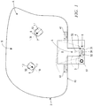
- This in Fig. 1 illustrated tillage system S comprises at least one self-propelled tillage implement 1.1, 1.2 for processing a predetermined work area A.
- two tillage machines 1.1 and 1.2 are provided for the common processing of the work area A.
- the tillage system S may include fewer or more tillage implements.
- Each individual tillage device 1.1, 1.2 operates autonomously and autonomously travels within the work area A a random, predetermined or independently planned route W from.
- the working area A of the tillage system S is limited by a wire 43.
- the wire 43 forms a boundary of the working area A and is laid in particular as a closed wire loop 2.
- the terminal ends 3 and 4 of the wire loop 2 are connected to a transmitting / receiving unit 5 of a base station 8.
- terminal ends 3 and 4 of the wire 43 are connected to a transmitting unit 32.
- Via the transmitting unit 32 - preferably at fixed intervals - electrical wire signals 41 are transmitted on the wire 43 of the deckle.
- the terminal ends 3 and 4 of the wire 43 of the wire loop 2 are connected to a receiving unit 31 which electrically receives the wire signal 41 sent to the wire 43 of the deckle.
- the receiving unit 31 and the transmitting unit 32 are connected to one another via a signal conditioning device 30.
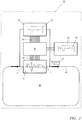
- the receiving unit 31, the signal processing device 30 and the transmitting unit 32 together with the wire of the closed wire loop 2 form a control circuit 38 (FIG. Fig. 3 ).
- the function of the control circuit 38 will be described in detail below.
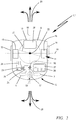
- Fig. 2 is schematically shown in plan view of a harrow 1.1, which is designed as a lawn mower 10.
- the illustration of the autonomously operating, self-propelled lawn mower 10 is exemplary.
- the tillage device 1.1 can also be designed as a scarifier, sweeper, vacuum cleaner, autonomously driving ride-on mower or the like tillage implement.
- the mower 10 shown by way of example consists essentially of a chassis with rear drive wheels 13 and 14 and a drive 11.
- the drive 11 consists of two independently controllable electric motors.
- a particular self-steering third wheel 17 is provided in the front region 12 of the housing 9 of the harrow 1.1 .
- the third wheel 17 is preferably located on a longitudinal central axis 18 of the housing 9 of the lawnmower 10.
- the formation of a chassis with four wheels may be appropriate.
- the drive wheels 13, 14 of the tillage device 1.1 shown rotate about a common drive shaft 19.
- the drive shaft 19 is - in plan view of the Lawnmower 10 after Fig. 2 - In particular at right angles to the longitudinal center axis 18 of the housing 9.
- For a straight ahead drive wheels 13 and 14 are to drive synchronously via their electric drive motors 15 and 16.
- the drive wheels 13, 14 are driven by their drive motors 15, 16 with, for example, different speeds.
- the harrow 1.1 in any desired direction of travel 20 according to the arrows shown to move forward or backward.
- the working tool 21 is a cutting blade rotating about a vertical axis of rotation 22.
- control of the electric drive motors 15 and 16 via a control unit 23 which is connected via schematically indicated electrical lines 29 to the electric drive motors 15 and 16.
- the wire signal 41 sent on the wire 43 of the wire loop 2 of the edge boundary is received in receiver coils 6 and 7 of the tillage device 1.1.
- the receiving coils 6 and 7 are in the front region 12 of the housing 9 each on one side of the longitudinal central axis 18 of the harrow 1.1.
- the received signals induced in the receiving coils 6 and 7 due to the transmitted wire signals 41 are fed to a common evaluation unit 24, which is connected to the control unit 23.
- the control unit 23 further comprises a memory 25 for an operating variable, which is useful for the operation of the tillage device 1.1.
- Such an operating variable may be, for example, the start time of the operation, the duration of the operation, the cutting height (when trained as a lawnmower), the route to a charging station, a mowing schedule as a weekly schedule, or the like operating variable.
- an input field 26 is shown, which advantageously has a screen 27 and input keys. It may be expedient to design the screen as a touch screen, so that input keys can be omitted.
- Each tillage device 1.1, 1.2 may further comprise a further receiver 50, which receives radio signals or infrared signals of a station transmitter 51.
- a station transmitter 51 may be provided, for example, at the base station 8 of the tillage system S, as in FIG Fig. 1 shown.
- the station transmitter 51 sends signals to the receiver 50 of the tillage implement 1.1.
- This wireless communication connection between the station transmitter 51 and the receiver 50 on the harrow 1.1 is advantageously designed as a radio link or the like. Possible radio links can be WLAN connections, Bluetooth connections, GSM connections, NFC connections or similar wireless connections.
- the station transmitter and the receiver are designed such that a transmission and reception of data is possible in both directions.
- the electrical supply of the control unit 23 and all its components, the electrical supply of the electric drive 11 and the electrical supply of the receiver 50 is ensured by an on-board battery 28 of the tillage device 1.1.
- the battery 28 is preferably inserted into the housing 9 of the tillage device 1.1.
- the tillage devices 1.1 and 1.2 are moved independently of one another in the work area A to be processed by corresponding activation of the drive motors 15 and 16.
- Each individual tillage implement 1.1 and 1.2 operates autonomously according to the information stored in its memory 25 operating variables.
- a coupling finger 52 may be provided, which enters into a corresponding coupling bushing 53 of the soil cultivation device 1.1 and establishes an electrical connection for charging the onboard battery 28.
- the wire signal 41 sent by the transmitting unit 32 is received electrically in the receiving unit 31 via the connection to the terminal ends 3 and 4.
- the wire signal 41 sent on the wire 43 varies in amplitude and waveform due to the geometric and electrical properties of the wire 43. Both the ohmic resistance of the wire 43 and the inductive and capacitive properties of a threaded wire loop 2 affect the wire signal 41 Signal distortions due to interference occur.
- the transmitted wire signal 41 from the tillage equipment 1.1, 1.2 over the entire length of the wire 43 of the deckle also with distance from the wire 43 is safe to receive.
- the received wire signal 42 should despite line losses on the wire loop 2 have an amplitude and / or waveform that ensures error-free control of the tillage equipment 1.1 and 1.2 throughout the work area.
- the signal conditioning device 30 compares the received wire signal 42 with a predetermined desired signal 40, which the signal conditioning device 30 expediently provided via a memory 35 is.
- the predetermined desired signal 40 may be a signal which satisfies legal requirements and is generally permissible on the wire 43 of the boundary. If the signal processing device 30 detects deviations from the predetermined setpoint signal 40, control commands are passed on via a line connection 34 to the transmitting unit 32, by means of which the wire signal 41 to be transmitted is changed in its amplitude I, its frequency, its signal form or similar signal variables.
- the transmitted wire signal 41 is modified according to the control commands and sent on the wire loop 2.
- the transmitted wire signal 41 is electrically tapped in the receiving unit 31 from the terminal ends 3, 4 of the wire loop 2 and received again.
- the received wire signal 42 of the signal conditioning device 30 is provided and compared by this with the predetermined desired signal 40. If further deviations from the setpoint signal 40 are detected, variables of the signal (amplitude, signal shape, time characteristic) are again changed and the wire signal 41 modified in this way is sent again via the connection ends 3, 4 of the wire 43 of the wire loop 2.
- the transmitting unit 32, the wire 43 of the wire loop 2, the receiving unit 31 and the signal processing device 30 form a control loop, in particular a closed loop.
- the adaptation of the transmitted wire signal 41 takes place until the received wire signal 42 approaches the predefined setpoint signal 40, preferably corresponds to the setpoint signal 40. It should be emphasized that the transmitted wire signal 41 and the predetermined target signal 40 may be formed differently in the amplitude I and / or the signal shape.
Landscapes
- Engineering & Computer Science (AREA)
- Physics & Mathematics (AREA)
- Aviation & Aerospace Engineering (AREA)
- Radar, Positioning & Navigation (AREA)
- Remote Sensing (AREA)
- General Physics & Mathematics (AREA)
- Automation & Control Theory (AREA)
- Life Sciences & Earth Sciences (AREA)
- Environmental Sciences (AREA)
- Computer Networks & Wireless Communication (AREA)
- Signal Processing (AREA)
- Electromagnetism (AREA)
- Theoretical Computer Science (AREA)
- Mathematical Physics (AREA)
- Computing Systems (AREA)
- Control Of Position, Course, Altitude, Or Attitude Of Moving Bodies (AREA)
- Agricultural Machines (AREA)
- Guiding Agricultural Machines (AREA)
Abstract
Description
- Die Erfindung betrifft ein Bodenbearbeitungssystem aus mindestens einem selbstfahrenden Bodenbearbeitungsgerät, das einen Antrieb und eine Steuereinheit aufweist. Es ist ein durch einen Randbegrenzungsdraht begrenzter Arbeitsbereich vorgesehen, wobei das Bodenbearbeitungsgerät in dem Arbeitsbereich einen durch die Steuereinheit bestimmten Fahrweg abfährt. Es ist eine Basisstation mit einer an den elektrischen Randbegrenzungsdraht angeschlossenen Sendeeinheit vorgesehen, über die ein Drahtsignal auf dem Randbegrenzungsdraht gesendet wird. Das elektromagnetische Feld des Drahtsignals wird in einer Empfangsspule des Bodenbearbeitungsgerätes ein Empfangssignal induzieren, welches in der Steuereinheit zur Bestimmung des Fahrwegs und des Fahrverhaltens verarbeitet wird.
- Die Begrenzung des Arbeitsbereichs für ein Bodenbearbeitungsgerät durch einen körperlichen verlegten Draht hat sich in der Praxis bewährt. Immer größer werdende Arbeitsbereiche werden funktionssicher durch eine derartige Randbegrenzung festgelegt, wobei auch unterschiedlich ausgebildete Arbeitsbereiche durch Fahrgassen verbunden sein können. In einem derartigen von einem Draht umschlossenen Gesamtarbeitsbereich kann nicht nur ein einzelnes Bodenbearbeitungsgerät eingesetzt werden, sondern auch mehrere Bodenbearbeitungsgeräte. Vorteilhaft wird bei mehreren Bodenbearbeitungsgeräten bei gleichem Arbeitsergebnis die Gesamtbetriebszeit des Bodenbearbeitungssystems reduziert.
- Jeder körperlich als Randbegrenzung verlegte Draht hat zunächst ohm'sche Eigenschaften und in Abhängigkeit von der verlegten Form und den verlegten Fahrgassen auch induktive oder kapazitive Eigenschaften. Daher wird ein auf den Draht aufgegebenes Drahtsignal über die Gesamtlänge des Drahtes gedämpft. Das Drahtsignal ändert sich in Amplitude und Signalform aufgrund der geometrischen und elektrischen Eigenschaften des Drahtes. Daher kann eine ordnungsgemäße Steuerung der Bodenbearbeitungsgeräte insbesondere bei einem größeren Abstand zum Draht beeinträchtigt sein.
- Bei einem Betrieb eines Bodenbearbeitungssystems sind ferner gesetzliche Anforderungen zu erfüllen. So dürfen die gesendeten Drahtsignale nicht beliebig stark sein, da deren elektromagnetisches Feld andere, z. B. benachbarte Bodenbearbeitungssysteme in ihrer Funktion beeinträchtigen würden. Wird das Drahtsignal hingegen elektrisch zu schwach ausgelegt, können im Umfeld des Bodenbearbeitungsgerätes auftretende Störsignale die Funktionssicherheit des Betriebs der Bodenbearbeitungsgeräte beeinträchtigen.
- Der Erfindung liegt die Aufgabe zugrunde, ein Bodenbearbeitungssystem mit einem Draht als Randbegrenzung eines Arbeitsbereiches derart auszubilden, dass einerseits über die gesamte Länge des Drahtes einer Randbegrenzung ein für die fehlerfreie Funktion der Bodenbearbeitungsgeräte ausreichend starkes Drahtsignal anliegt und andererseits eine elektromagnetische Beeinträchtigung des Umfeldes minimiert ist.
- Die Aufgabe wird nach den Merkmalen des Anspruchs 1 gelöst.
- Das auf dem Draht der Randbegrenzung gesendete Drahtsignal wird insbesondere parallel zur Sendeeinheit von einer Empfangseinheit der Basisstation elektrisch empfangen. Dieses empfangene Drahtsignal wird mit einem vorgegebenen Sollsignal verglichen, um bei einer Abweichung des empfangenen Drahtsignals von dem vorgegebenen Sollsignal das gesendete Drahtsignal zu verändern. In besonderer Ausbildung der Erfindung wird das empfangene Drahtsignal derart verändert, dass es dem vorgegebenen Sollsignal angenähert ist oder diesem insbesondere entspricht.
- Hervorzuheben ist, dass die Empfangseinheit das gesendete Drahtsignal zeitgleich mit dem Senden vom Draht elektrisch abgreift, so dass das gesendete Drahtsignal zeitgleich in der Empfangseinheit gemessen wird. Empfangseinheit und Sendeeinheit sind in derselben Basisstation vorgesehen und arbeiten unabhängig von der Länge des Drahtes und der verlegten geometrischen Form des Drahtes. Es sind vom Benutzer keine Eingaben zur verlegten Randbegrenzung, zur Länge des verlegten Drahtes oder zum Abstand von parallel verlaufenden Drahtabschnitten einzugeben. Auch kann auf Sensoren z. B. zur Erfassung des elektromagnetischen Feldes verzichtet werden. Die Basisstation passt das gesendete Drahtsignal ohne Eingriffe durch den Benutzer selbstständig optimal an.
- Durch die Signalanpassung des gesendeten Drahtsignals kann die Dämpfung des Drahtsignals, insbesondere die ohmschen, induktiven und/oder kapazitiven Einflussfaktoren des als Randbegrenzung verlegten Drahtes in hohem Maße kompensiert werden. So kann über die Signalaufbereitungsvorrichtung das zu sendende Drahtsignal in seiner Amplitude, seiner Signalform und/oder in seinem zeitlichen Verlauf angepasst werden.
- Das vorgegebene Sollsignal muss nicht zwingend dem gesendeten Drahtsignal entsprechen. Vielmehr können sich das gesendete Drahtsignal und das vorgegebene Sollsignal in der Amplitude und/oder der Signalform unterscheiden. Auch kann es zweckmäßig sein, der Signalaufbereitungsvorrichtung eine Auswahl von zulässigen Sollsignalen zur Verfügung zu stellen. Die Signalaufbereitungsvorrichtung kann in Abhängigkeit der festgestellten Abweichungen des empfangenen Drahtsignals von einem vorgegebenen Sollsignal entscheiden, welche Signalform, Signalstärke und Signalzeit für die angeschlossene Drahtschleife vorteilhaft ist. So kann - ohne dass ein Benutzer eingreifen muss - jeder vor Ort in beliebiger Form verlegte Draht als Randbegrenzung mit einem optimalen Drahtsignal betrieben werden, wodurch eine ausfallsichere Steuerung der Bodenbearbeitungsgeräte im gesamten Arbeitsbereich gewährleistet ist.
- Körperlich ist der Draht der Randbegrenzung als Drahtschleife verlegt, wobei die Drahtschleife an ihren Anschlussenden mit einer Sendeeinheit elektrisch verbunden ist. Zweckmäßig ist die Empfangseinheit elektrisch parallel zur Sendeeinheit an den Draht der Randbegrenzung angeschlossen. In einfacher Weise sind die Anschlussenden der Drahtschleife mit der Empfangseinheit elektrisch verbunden. Die Sendeeinheit und die Empfangseinheit kommunizieren in Weiterbildung der Erfindung über eine Signalaufbereitungsvorrichtung miteinander. Die Sendeeinheit, der Draht der Randbegrenzung, die Empfangseinheit und die Signalaufbereitungsvorrichtung bilden einen Regelkreis.
- Die Signalaufbereitungsvorrichtung bestimmt in Abhängigkeit der festgestellten Abweichungen zwischen dem empfangenen Drahtsignal und dem vorgegebenen Sollsignal, ob das zu sendende Drahtsignal zu verändern ist, z.B. in seiner Amplitude zu verstärken ist, in seiner Signalform zu verändern ist oder in seinem zeitlichen Verlauf wie z. B. in der Frequenz anzupassen ist.
- In vorteilhafter Weiterbildung der Erfindung ist die Basisstation zugleich als Ladestation für einen Akku des Bodenbearbeitungsgerätes ausgebildet. Hierzu fährt das Bodenbearbeitungsgerät bei entsprechend niedrigem Ladezustand des bordeigenen Akkus in die Basisstation als Ladestation ein.
- Vorteilhaft ist das Bodenbearbeitungsgerät ein selbstfahrender Rasenmäher.
- Die weiteren Merkmale der Erfindung ergeben sich aus den weiteren Ansprüchen, der Beschreibung und der Zeichnung, in der ein nachstehend im Einzelnen beschriebenes Ausführungsbeispiel der Erfindung dargestellt ist. Es zeigen:
- Fig. 1
- in schematischer Darstellung ein Bodenbearbeitungssystem aus mehreren, in einem Arbeitsbereich selbstfahrenden Bodenbearbeitungsgeräten,
- Fig. 2
- in schematischer Darstellung den Aufbau eines Bodenbearbeitungsgerätes am Beispiel eines selbstfahrenden Rasenmähers,
- Fig. 3
- in schematischer Darstellung einen Regelkreis zur Anpassung eines auf einen Draht einer Randbegrenzung gesendeten Drahtsignals.
- Das in
Fig. 1 dargestellte Bodenbearbeitungssystem S umfasst zumindest ein selbstfahrendes Bodenbearbeitungsgerät 1.1, 1.2 zur Bearbeitung eines vorgegebenen Arbeitsbereichs A. Im gezeigten Ausführungsbeispiel sind zwei Bodenbearbeitungsgeräte 1.1 und 1.2 zur gemeinsamen Bearbeitung des Arbeitsbereiches A vorgesehen. Das Bodenbearbeitungssystem S kann weniger oder auch mehr Bodenbearbeitungsgeräte umfassen. Jedes einzelne Bodenbearbeitungsgerät 1.1, 1.2 arbeitet autonom und fährt innerhalb des Arbeitsbereiches A selbstständig einen zufälligen, vorgegebenen oder selbstständig geplanten Fahrweg W ab. - Im gezeigten Ausführungsbeispiel nach
Fig. 1 ist der Arbeitsbereich A des Bodenbearbeitungssystems S durch einen Draht 43 begrenzt. Der Draht 43 bildet eine Randbegrenzung des Arbeitsbereichs A und ist insbesondere als geschlossene Drahtschleife 2 verlegt. Die Anschlussenden 3 und 4 der Drahtschleife 2 sind an eine Sende-/Empfangseinheit 5 einer Basisstation 8 angeschlossen. WieFig. 1 zeigt, sind Anschlussenden 3 und 4 des Drahtes 43 mit einer Sendeeinheit 32 verbunden. Über die Sendeeinheit 32 werden - bevorzugt in zeitlich festen Abständen - elektrische Drahtsignale 41 auf dem Draht 43 der Randbegrenzung gesendet. - Insbesondere elektrisch parallel zur Sendeeinheit 32 sind die Anschlussenden 3 und 4 des Drahtes 43 der Drahtschleife 2 mit einer Empfangseinheit 31 verbunden, welche das auf den Draht 43 der Randbegrenzung gesendete Drahtsignal 41 elektrisch empfängt. Die Empfangseinheit 31 und die Sendeeinheit 32 sind über eine Signalaufbereitungsvorrichtung 30 miteinander verbunden.
- Die Empfangseinheit 31, die Signalaufbereitungsvorrichtung 30 und die Sendeeinheit 32 bilden zusammen mit dem Draht der geschlossenen Drahtschleife 2 einen Regelkreis 38 (
Fig. 3 ). Die Funktion des Regelkreises 38 wird nachfolgend im Einzelnen beschrieben. - In
Fig. 2 ist in Draufsicht schematisch ein Bodenbearbeitungsgerät 1.1 gezeigt, welches als Rasenmäher 10 ausgebildet ist. Die Darstellung des autonom arbeitenden, selbstfahrenden Rasenmähers 10 ist beispielhaft. Das Bodenbearbeitungsgerät 1.1 kann auch als Vertikutierer, Kehrmaschine, Staubsauger, autonom fahrender Aufsitzmäher oder dergleichen Bodenbearbeitungsgerät ausgebildet sein. - Der beispielhaft gezeigte Rasenmäher 10 besteht im Wesentlichen aus einem Fahrwerk mit hinteren Antriebsrädern 13 und 14 und einem Antrieb 11. Im gezeigten Ausführungsbeispiel ist jedem Antriebsrad 13, 14 ein elektrischer Antriebsmotor 15, 16 zugeordnet, so dass die Antriebsräder 13 und 14 zur Richtungssteuerung des Rasenmähers 10 mit unterschiedlicher Drehzahl und/oder in unterschiedlicher Drehrichtung angetrieben werden können. Der Antrieb 11 besteht aus zwei unabhängig voneinander ansteuerbaren Elektromotoren.
- Im vorderen Bereich 12 des Gehäuses 9 des Bodenbearbeitungsgerätes 1.1 ist ein insbesondere selbstlenkendes drittes Rad 17 vorgesehen. Das dritte Rad 17 liegt vorzugsweise auf einer Längsmittelachse 18 des Gehäuses 9 des Rasenmähers 10. Die Ausbildung eines Fahrgestells mit vier Rädern kann zweckmäßig sein.
- Die Antriebsräder 13, 14 des gezeigten Bodenbearbeitungsgerätes 1.1 drehen um eine gemeinsame Antriebsachse 19. Die Antriebsachse 19 liegt - in Draufsicht auf den Rasenmäher 10 nach
Fig. 2 - insbesondere rechtwinklig zur Längsmittelachse 18 des Gehäuses 9. Für eine Geradeausfahrt sind die Antriebsräder 13 und 14 über ihre elektrischen Antriebsmotoren 15 und 16 synchron anzutreiben. Für eine Kurvenfahrt werden die Antriebsräder 13, 14 durch ihre Antriebsmotoren 15, 16 mit zum Beispiel unterschiedlichen Drehzahlen angetrieben. Durch den Antrieb 11 ist das Bodenbearbeitungsgerät 1.1 in jeder gewünschten Fahrtrichtung 20 gemäß den dargestellten Pfeilen vorwärts oder rückwärts zu bewegen. - Im Ausführungsbeispiel als Rasenmäher 10 weist das Bodenbearbeitungsgerät 1.1 nach
Fig. 2 zwischen den Antriebsrädern 13 und 14 ein Arbeitswerkzeug 21 auf. Bei einem Rasenmäher 10 ist das Arbeitswerkzeug 21 ein um eine senkrechte Drehachse 22 rotierendes Schneidmesser. - Die Steuerung der elektrischen Antriebsmotoren 15 und 16 erfolgt über eine Steuereinheit 23, die über schematisch angedeutete elektrische Leitungen 29 mit den elektrischen Antriebsmotoren 15 und 16 verbunden ist.
- Das auf dem Draht 43 der Drahtschleife 2 der Randbegrenzung gesendete Drahtsignal 41 wird in Empfangsspulen 6 und 7 des Bodenbearbeitungsgerätes 1.1 empfangen. Die Empfangsspulen 6 und 7 liegen im vorderen Bereich 12 des Gehäuses 9 jeweils auf einer Seite der Längsmittelachse 18 des Bodenbearbeitungsgerätes 1.1. Die aufgrund der gesendeten Drahtsignale 41 in den Empfangsspulen 6 und 7 induzierten Empfangssignale werden einer gemeinsamen Auswerteeinheit 24 zugeführt, die mit der Steuereinheit 23 verbunden ist. Vorteilhaft umfasst die Steuereinheit 23 ferner einen Speicher 25 für eine Betriebsvariable, die zum Betrieb des Bodenbearbeitungsgerätes 1.1 zweckmäßig ist. Eine derartige Betriebsvariable kann zum Beispiel die Startzeit des Betriebs sein, die Dauer des Betriebs, die Schnitthöhe (bei einer Ausbildung als Rasenmäher), der Fahrweg zu einer Ladestation, ein Mähplan als Wochenplan oder dergleichen Betriebsvariable.
- In
Fig. 2 ist zur Eingabe von Informationen zur Betriebsvariablen durch den Benutzer ein Eingabefeld 26 dargestellt, welches vorteilhaft einen Bildschirm 27 und Eingabetasten aufweist. Es kann zweckmäßig sein, den Bildschirm als Touchscreen auszubilden, so dass Eingabetasten entfallen können. - Jedes Bodenbearbeitungsgerät 1.1, 1.2 kann ferner einen weiteren Empfänger 50 aufweisen, der Funksignale oder Infrarotsignale eines Stationssender 51 empfängt. Ein derartiger Stationssender 51 kann zum Beispiel an der Basisstation 8 des Bodenbearbeitungssystems S vorgesehen sein, wie in
Fig. 1 dargestellt. Der Stationssender 51 sendet Signale an den Empfänger 50 des Bodenbearbeitungsgerätes 1.1. Diese drahtlose Kommunikationsverbindung zwischen dem Stationssender 51 und dem Empfänger 50 auf dem Bodenbearbeitungsgerät 1.1 ist vorteilhaft als Funkstrecke oder dergleichen ausgebildet. Mögliche Funkstrecken können WLAN-Verbindungen, Bluetooth-Verbindungen, GSM-Verbindungen, NFC-Verbindungen oder dergleichen drahtlose Verbindungen sein. In besonderer Ausgestaltung der Erfindung ist der Stationssender und der Empfänger derart ausgebildet, dass in beiden Richtungen ein Senden und ein Empfangen von Daten möglich ist. - Die elektrische Versorgung der Steuereinheit 23 und all ihrer Komponenten, die elektrische Versorgung des elektrischen Antriebs 11 sowie die elektrische Versorgung des Empfängers 50 wird durch einen bordeignen Akku 28 des Bodenbearbeitungsgerätes 1.1 gewährleistet. Der Akku 28 ist bevorzugt in das Gehäuse 9 des Bodenbearbeitungsgerätes 1.1 eingeschoben.
- Im Betrieb des Bodenbearbeitungssystems S werden die Bodenbearbeitungsgeräte 1.1 und 1.2 voneinander unabhängig in dem zu bearbeitenden Arbeitsbereich A durch entsprechende Ansteuerung der Antriebsmotoren 15 und 16 verfahren. Jedes einzelne Bodenbearbeitungsgerät 1.1 und 1.2 arbeitet autonom entsprechend der Information einer in seinem Speicher 25 abgelegten Betriebsvariablen.
- Da im Betrieb eines Bodenbearbeitungsgerätes 1.1, 1.2 die Akkuladung aufgrund der betriebenen elektrischen Verbraucher abnimmt, ist zweckmäßig vorgesehen, die Basisstation 8 des Bodenbearbeitungssystems S zugleich als Ladestation L auszubilden, wie in
Fig. 1 angedeutet ist. So kann ein Kupplungsfinger 52 vorgesehen sein, der in eine entsprechende Kupplungsbuchse 53 des Bodenbearbeitungsgerätes 1.1 einfährt und eine elektrische Verbindung zur Aufladung des bordeignen Akkus 28 herstellt. - Um zu gewährleisten, dass über die gesamte Länge des Drahtes 43 der Randbegrenzung ein ausreichend starkes Drahtsignal 41 anliegt, wird das von der Sendeeinheit 32 gesendete Drahtsignal 41 über die Verbindung mit den Anschlussenden 3 und 4 elektrisch in der Empfangseinheit 31 empfangen. Das auf dem Draht 43 gesendete Drahtsignal 41 ändert sich in Amplitude und Signalform aufgrund der geometrischen und elektrischen Eigenschaften des Drahtes 43. Sowohl der ohm'sche Widerstand des Drahtes 43 als auch induktive und kapazitive Eigenschaften einer verlegten Drahtschleife 2 beeinflussen das Drahtsignal 41. Ferner können Signalverfälschungen durch Störsignale auftreten.
- Für einen ordnungsgemäßen Betrieb des Bodenbearbeitungssystems S ist zu gewährleisten, dass das gesendete Drahtsignal 41 von den Bodenbearbeitungsgeräten 1.1, 1.2 über die gesamte Länge des Drahtes 43 der Randbegrenzung auch mit Abstand zum Draht 43 sicher zu empfangen ist. Das empfangene Drahtsignal 42 soll trotz Leitungsverlusten auf der Drahtschleife 2 eine Amplitude und/oder Signalform haben, die eine fehlerfreie Steuerung der Bodenbearbeitungsgeräte 1.1 und 1.2 im gesamten Arbeitsbereich sicherstellt.
- Nach der Erfindung ist vorgesehen, das in der Empfangseinheit 31 empfangene Drahtsignal 42 über eine elektrische Leitungsverbindung 33 einer Signalaufbereitungsvorrichtung 30 zu übermitteln. Die Signalaufbereitungsvorrichtung 30 vergleicht das empfangene Drahtsignal 42 mit einem vorgegebenen Sollsignal 40, welches der Signalaufbereitungsvorrichtung 30 zweckmäßig über einen Speicher 35 zur Verfügung gestellt ist. Das vorgegebene Sollsignal 40 kann ein Signal sein, welches gesetzlichen Anforderungen genügt und auf dem Draht 43 der Randbegrenzung grundsätzlich zulässig ist. Stellt die Signalaufbereitungsvorrichtung 30 Abweichungen zum vorgegebenen Sollsignal 40 fest, werden über eine Leitungsverbindung 34 zur Sendeeinheit 32 Steuerungsbefehle weitergegeben, durch die das zu sendende Drahtsignal 41 in seiner Amplitude I, seiner Frequenz, seiner Signalform oder dergleichen Signalvariablen verändert wird. Das gesendete Drahtsignal 41 wird entsprechend den Steuerungsbefehlen modifiziert und auf der Drahtschleife 2 gesendet.
- Das gesendete Drahtsignal 41 wird in der Empfangseinheit 31 von den Anschlussenden 3, 4 der Drahtschleife 2 elektrisch abgegriffen und erneut empfangen. Über die Leitungsverbindung 33 wird das empfangene Drahtsignal 42 der Signalaufbereitungsvorrichtung 30 zur Verfügung gestellt und von dieser mit dem vorgegebenen Sollsignal 40 verglichen. Werden weiterhin Abweichungen von dem Sollsignal 40 festgestellt, werden erneut Variable des Signals (Amplitude, Signalform, Zeitverlauf) geändert und das so modifizierte Drahtsignal 41 erneut über die Anschlussenden 3, 4 des Drahtes 43 der Drahtschleife 2 gesendet. Die Sendeeinheit 32, der Draht 43 der Drahtschleife 2, die Empfangseinheit 31 und die Signalaufbereitungsvorrichtung 30 bilden einen Regelkreis, insbesondere einen geschlossenen Regelkreis. Die Anpassung des gesendeten Drahtsignals 41 erfolgt so lange, bis das empfange Drahtsignal 42 dem vorgegebenen Sollsignal 40 angenähert ist, vorzugsweise dem Sollsignal 40 entspricht. Hervorzuheben ist, dass das gesendete Drahtsignal 41 und das vorgegebene Sollsignal 40 in der Amplitude I und/oder der Signalform unterschiedlich ausgebildet sein können.
- Weitere vorteilhafte Ausführungsbeispiele der Erfindung ergeben sich durch beliebige Kombinationen der angegebenen Merkmale und der beschriebenen Ausführungsbeispiele.
Claims (12)
- Bodenbearbeitungssystem aus mindestens einem selbstfahrenden Bodenbearbeitungsgerät (1.1, 1.2), wobei das Bodenbearbeitungsgerät (1.1, 1.2) einen Antrieb (11) und eine Steuereinheit (23) aufweist, und mit einem durch einen Draht (43) begrenzten Arbeitsbereich (A), wobei das Bodenbearbeitungsgerät (1.1, 1.2) in dem Arbeitsbereich (A) einen durch die Steuereinheit (23) bestimmten Fahrweg (W) abfährt, und mit einer Basisstation (8) mit einer elektrisch an den Draht (43) angeschlossenen Sendeeinheit (32), über die ein Drahtsignal (41) auf dem Draht (43) gesendet wird, wobei das elektromagnetische Feld des Drahtsignals (41) in einer Empfangsspule (6, 7) des Bodenbearbeitungsgerätes (1.1, 1.2) ein Empfangssignal induziert, und das induzierte Empfangssignal in der Steuereinheit (23) verarbeitet wird,
dadurch gekennzeichnet, dass das auf dem Draht (43) gesendete Drahtsignal (41) von einer Empfangseinheit (31) der Basisstation (8) elektrisch empfangen wird, dass das empfangene Drahtsignal (42) mit einem vorgegebenen Sollsignal (40) verglichen wird, und dass bei einer Abweichung des elektrisch empfangenen Drahtsignals (42) vom vorgegebenen Sollsignal (40) das gesendete Drahtsignal (41) verändert wird. - Bodenbearbeitungssystem nach Anspruch 1,
dadurch gekennzeichnet, dass das gesendete Drahtsignal (41) derart verändert wird, dass das empfangene Drahtsignal (42) dem vorgegebenen Sollsignal (40) angepasst ist. - Bodenbearbeitungssystem nach Anspruch 1,
dadurch gekennzeichnet, dass das gesendete Drahtsignal (41) und das vorgegebene Sollsignal (40) in der Amplitude (I) und/oder der Signalform unterschiedlich sind. - Bodenbearbeitungssystem nach Anspruch 1,
dadurch gekennzeichnet, dass der Draht (43) als eine Randbegrenzung des Arbeitsbereichs (A) bildende Drahtschleife (2) verlegt ist. - Bodenbearbeitungssystem nach Anspruch 4,
dadurch gekennzeichnet, dass die Drahtschleife (2) an ihren Anschlussenden (3, 4) mit einer Sendeeinheit (32) elektrisch verbunden ist. - Bodenbearbeitungssystem nach Anspruch 5,
dadurch gekennzeichnet, dass die Drahtschleife (2) an ihren Anschlussenden (3, 4) mit einer Empfangseinheit (31) elektrisch verbunden ist. - Bodenbearbeitungssystem nach Anspruch 6,
dadurch gekennzeichnet, dass die Empfangseinheit (31) über eine Signalaufbereitungsvorrichtung (30) mit der Sendeeinheit (32) verbunden ist. - Bodenbearbeitungssystem nach Anspruch 7,
dadurch gekennzeichnet, dass die Sendeeinheit (32), der Draht (43), die Empfangseinheit (31) und die Signalaufbereitungsvorrichtung (30) einen Regelkreis (38) bilden. - Bodenbearbeitungssystem nach Anspruch 1,
dadurch gekennzeichnet, dass das gesendete Drahtsignal (41) in seiner Amplitude (I) elektrisch verstärkt wird. - Bodenbearbeitungssystem nach Anspruch 1,
dadurch gekennzeichnet, dass das gesendete Drahtsignal (41) in seiner Signalform geändert wird. - Bodenbearbeitungssystem nach Anspruch 1,
dadurch gekennzeichnet, dass die Basisstation (8) als Ladestation (L) für einen Akku (28) des Bodenbearbeitungsgerätes (1.1, 1.2) ausgebildet ist. - Bodenbearbeitungssystem nach Anspruch 1,
dadurch gekennzeichnet, dass das Bodenbearbeitungsgerät (1.1, 1.2) ein selbstfahrender Rasenmäher (10) ist.
Priority Applications (3)
| Application Number | Priority Date | Filing Date | Title |
|---|---|---|---|
| EP17400031.5A EP3412131B1 (de) | 2017-06-09 | 2017-06-09 | Bodenbearbeitungssystem mit signalanpassung |
| US15/997,346 US10820493B2 (en) | 2017-06-09 | 2018-06-04 | Ground working system with signal adaptation |
| CN201810586125.5A CN109039385A (zh) | 2017-06-09 | 2018-06-08 | 具有信号匹配的耕作系统 |
Applications Claiming Priority (1)
| Application Number | Priority Date | Filing Date | Title |
|---|---|---|---|
| EP17400031.5A EP3412131B1 (de) | 2017-06-09 | 2017-06-09 | Bodenbearbeitungssystem mit signalanpassung |
Publications (2)
| Publication Number | Publication Date |
|---|---|
| EP3412131A1 true EP3412131A1 (de) | 2018-12-12 |
| EP3412131B1 EP3412131B1 (de) | 2020-11-11 |
Family
ID=59276668
Family Applications (1)
| Application Number | Title | Priority Date | Filing Date |
|---|---|---|---|
| EP17400031.5A Active EP3412131B1 (de) | 2017-06-09 | 2017-06-09 | Bodenbearbeitungssystem mit signalanpassung |
Country Status (3)
| Country | Link |
|---|---|
| US (1) | US10820493B2 (de) |
| EP (1) | EP3412131B1 (de) |
| CN (1) | CN109039385A (de) |
Cited By (1)
| Publication number | Priority date | Publication date | Assignee | Title |
|---|---|---|---|---|
| DE102019201692A1 (de) * | 2019-02-11 | 2020-08-13 | Zf Friedrichshafen Ag | Verfahren und System zur Begrenzung und Überwachung mindestens eines Arbeitsbereichs für zumindest ein autonom betriebenes Fahrzeug |
Families Citing this family (17)
| Publication number | Priority date | Publication date | Assignee | Title |
|---|---|---|---|---|
| EP3412135B1 (de) | 2017-06-09 | 2022-09-14 | Andreas Stihl AG & Co. KG | Bodenbearbeitungssystem mit mindestens einer ladestation mit einer datenverbindung |
| EP3412134B1 (de) | 2017-06-09 | 2020-08-19 | Andreas Stihl AG & Co. KG | Bodenbearbeitungssystem mit einem endlosen begrenzungsdraht |
| EP3412132B1 (de) | 2017-06-09 | 2021-05-12 | Andreas Stihl AG & Co. KG | Bodenbearbeitungssystem mit mindestens einer intensivzone |
| EP3412133B1 (de) | 2017-06-09 | 2022-09-14 | Andreas Stihl AG & Co. KG | Bodenbearbeitungssystem mit mindestens einer ladestation |
| CN112438111B (zh) * | 2019-09-02 | 2021-12-28 | 深圳拓邦股份有限公司 | 一种割草机系统通信方法、割草机系统及割草机基站 |
| CN114679949B (zh) * | 2020-12-30 | 2024-03-15 | 南京泉峰科技有限公司 | 一种自驱动设备系统和充电站 |
| US12296694B2 (en) | 2021-03-10 | 2025-05-13 | Techtronic Cordless Gp | Lawnmowers |
| US12677737B2 (en) | 2021-03-10 | 2026-07-14 | Techtronic Cordless Gp | Lawnmowers |
| US12690518B2 (en) | 2021-03-10 | 2026-07-28 | Techtronic Cordless Gp | Lawnmower with airflow boost system |
| CA3181601A1 (en) | 2021-11-10 | 2023-05-10 | Techtronic Cordless Gp | Robotic lawn mowers |
| AU2023200381A1 (en) | 2022-01-31 | 2023-08-17 | Techtronic Cordless Gp | Robotic garden tool |
| CN116636380A (zh) | 2022-02-22 | 2023-08-25 | 创科无线普通合伙 | 具有刀片盖罩的园艺工具 |
| AU2023202361A1 (en) | 2022-04-20 | 2023-11-09 | Techtronic Cordless Gp | Garden tool power source compartment having drainage |
| EP4270138B1 (de) | 2022-04-28 | 2026-07-15 | Techtronic Cordless GP | Erzeugung einer virtuellen grenze für ein robotisches gartenwerkzeug |
| US12472611B2 (en) | 2022-05-31 | 2025-11-18 | Techtronic Cordless Gp | Peg driver |
| AU2023204696A1 (en) | 2022-07-19 | 2024-02-08 | Techtronic Cordless Gp | Display for controlling robotic tool |
| EP4340296B1 (de) | 2022-07-29 | 2025-04-09 | Techtronic Cordless GP | Erzeugung eines kryptoschlüssels für ein robotisches gartenwerkzeug |
Citations (3)
| Publication number | Priority date | Publication date | Assignee | Title |
|---|---|---|---|---|
| EP1906205A1 (de) * | 2006-09-29 | 2008-04-02 | F. Robotics Acquisitions Ltd. | System und Verfahren zur Bestimmung der Position einer Maschine |
| EP2667271A1 (de) * | 2012-05-23 | 2013-11-27 | Honda Motor Co., Ltd. | Unbemanntes autonomes System mit Wahl des Bereichsignals |
| WO2014158060A1 (en) * | 2013-02-20 | 2014-10-02 | Husqvarna Ab | A method and a robotic work tool system with a charging station and a boundary wire |
Family Cites Families (34)
| Publication number | Priority date | Publication date | Assignee | Title |
|---|---|---|---|---|
| SE0201739D0 (sv) | 2002-06-07 | 2002-06-07 | Electrolux Ab | Elektroniskt avgränsningssystem |
| US7126475B2 (en) * | 2004-08-17 | 2006-10-24 | Ho Yun So | Electronic fence transmitter for self-adjusting the receiving distance |
| US8306659B2 (en) | 2006-12-06 | 2012-11-06 | F Robotics Acquisitions Ltd. | Autonomous robot |
| CN101607399A (zh) | 2008-06-19 | 2009-12-23 | 鸿富锦精密工业(深圳)有限公司 | 充电装置 |
| DE102009001900A1 (de) * | 2008-10-20 | 2010-04-22 | Robert Bosch Gmbh | Verfahren und System zur Arbeitsbereichserkennung eines mobilen Arbeitsgerätes |
| DE102009027396A1 (de) | 2009-07-01 | 2011-01-13 | Robert Bosch Gmbh | Autonome mobile Plattform zur Flächenbearbeitung und Verfahren zur Flächenbearbeitung |
| US20110153172A1 (en) | 2009-12-23 | 2011-06-23 | Noel Wayne Anderson | Area management |
| US8744626B2 (en) | 2010-05-27 | 2014-06-03 | Deere & Company | Managing autonomous machines across multiple areas |
| EP2648307B1 (de) | 2010-11-30 | 2019-08-28 | Positec Power Tools (Suzhou) Co., Ltd | Automatische gehvorrichtung, ladestation, andocksystem und andockverfahren |
| KR101188891B1 (ko) | 2010-12-16 | 2012-10-09 | (주)마이크로인피니티 | 이미지 도안용 잔디관리장치 |
| US9276419B2 (en) | 2010-12-20 | 2016-03-01 | Positec Power Tools (Suzhou) Co., Ltd. | Robot, a docking system and a docking method |
| DE102011083309A1 (de) * | 2011-09-23 | 2013-03-28 | Robert Bosch Gmbh | Autonomes Arbeitsgerät |
| JP2013192678A (ja) | 2012-03-19 | 2013-09-30 | Sharp Corp | ロボット装置、情報提供装置、情報提供システム及びプログラム |
| EP2656718B1 (de) | 2012-04-24 | 2018-07-04 | Robert Bosch Gmbh | Bodenpflegeapparat und Ladestationsvorrichtung dafür |
| EP2741160B1 (de) | 2012-12-07 | 2016-10-12 | Viking GmbH | Verfahren zur Steuerung eines selbstfahrenden Rasenmähers |
| DE202013101894U1 (de) | 2013-04-30 | 2014-08-07 | Al-Ko Kober Ag | Basisstation für und Mähsystem mit mehreren Mährobotern |
| JP6105377B2 (ja) * | 2013-04-30 | 2017-03-29 | 株式会社クボタ | 作業機、及び、アプリケーションプログラム |
| US9573275B2 (en) | 2013-11-12 | 2017-02-21 | Husqvarna Ab | Navigation for a robotic working tool |
| CN203883787U (zh) * | 2014-05-14 | 2014-10-15 | 杭州菲沃机器人科技有限公司 | 一种智能割草机的电子篱笆电路 |
| US9375842B2 (en) | 2014-05-15 | 2016-06-28 | Irobot Corporation | Autonomous mobile robot confinement system |
| EP3653037B1 (de) | 2014-08-07 | 2022-12-21 | Positec Power Tools (Suzhou) Co., Ltd | Mähsystem mit einem automatischen mäher und einer drahtlosen ladestation |
| EP3553620B1 (de) | 2014-12-22 | 2023-07-12 | Husqvarna Ab | Grasstrukturdetektion durch ein robotisches fahrzeug |
| SE538373C2 (en) | 2014-12-23 | 2016-05-31 | Husqvarna Ab | Improved navigation for a robotic lawnmower |
| US10405488B2 (en) | 2014-12-23 | 2019-09-10 | Husqvarna Ab | Zone control system for a robotic vehicle |
| KR102398329B1 (ko) | 2015-03-16 | 2022-05-16 | 엘지전자 주식회사 | 이동 로봇의 충전 장치 및 그 제어방법 |
| SE538868C2 (en) | 2015-05-04 | 2017-01-17 | Husqvarna Ab | Improved error detection and resetting of a robotic work tool |
| US10034421B2 (en) | 2015-07-24 | 2018-07-31 | Irobot Corporation | Controlling robotic lawnmowers |
| DE102015114568A1 (de) | 2015-09-01 | 2017-03-02 | Claas Selbstfahrende Erntemaschinen Gmbh | Verfahren zum Betreiben von landwirtschaftlichen Arbeitsmaschinen |
| GB2560868B (en) * | 2016-09-29 | 2023-02-15 | Mtd Products Inc | Demarcating system |
| US10952369B2 (en) | 2017-04-24 | 2021-03-23 | Kubota Corporation | Grass management system |
| EP3412134B1 (de) | 2017-06-09 | 2020-08-19 | Andreas Stihl AG & Co. KG | Bodenbearbeitungssystem mit einem endlosen begrenzungsdraht |
| EP3412133B1 (de) | 2017-06-09 | 2022-09-14 | Andreas Stihl AG & Co. KG | Bodenbearbeitungssystem mit mindestens einer ladestation |
| EP3412132B1 (de) | 2017-06-09 | 2021-05-12 | Andreas Stihl AG & Co. KG | Bodenbearbeitungssystem mit mindestens einer intensivzone |
| EP3412135B1 (de) | 2017-06-09 | 2022-09-14 | Andreas Stihl AG & Co. KG | Bodenbearbeitungssystem mit mindestens einer ladestation mit einer datenverbindung |
-
2017
- 2017-06-09 EP EP17400031.5A patent/EP3412131B1/de active Active
-
2018
- 2018-06-04 US US15/997,346 patent/US10820493B2/en active Active
- 2018-06-08 CN CN201810586125.5A patent/CN109039385A/zh active Pending
Patent Citations (3)
| Publication number | Priority date | Publication date | Assignee | Title |
|---|---|---|---|---|
| EP1906205A1 (de) * | 2006-09-29 | 2008-04-02 | F. Robotics Acquisitions Ltd. | System und Verfahren zur Bestimmung der Position einer Maschine |
| EP2667271A1 (de) * | 2012-05-23 | 2013-11-27 | Honda Motor Co., Ltd. | Unbemanntes autonomes System mit Wahl des Bereichsignals |
| WO2014158060A1 (en) * | 2013-02-20 | 2014-10-02 | Husqvarna Ab | A method and a robotic work tool system with a charging station and a boundary wire |
Cited By (2)
| Publication number | Priority date | Publication date | Assignee | Title |
|---|---|---|---|---|
| DE102019201692A1 (de) * | 2019-02-11 | 2020-08-13 | Zf Friedrichshafen Ag | Verfahren und System zur Begrenzung und Überwachung mindestens eines Arbeitsbereichs für zumindest ein autonom betriebenes Fahrzeug |
| US12124273B2 (en) | 2019-02-11 | 2024-10-22 | Zf Friedrichshafen Ag | Method and system for delimiting and monitoring at least one working area for at least one autonomously operated vehicle |
Also Published As
| Publication number | Publication date |
|---|---|
| US10820493B2 (en) | 2020-11-03 |
| US20180352728A1 (en) | 2018-12-13 |
| EP3412131B1 (de) | 2020-11-11 |
| CN109039385A (zh) | 2018-12-18 |
Similar Documents
| Publication | Publication Date | Title |
|---|---|---|
| EP3412131B1 (de) | Bodenbearbeitungssystem mit signalanpassung | |
| EP3412134B1 (de) | Bodenbearbeitungssystem mit einem endlosen begrenzungsdraht | |
| EP3412133B1 (de) | Bodenbearbeitungssystem mit mindestens einer ladestation | |
| EP3412135B1 (de) | Bodenbearbeitungssystem mit mindestens einer ladestation mit einer datenverbindung | |
| EP3412132B1 (de) | Bodenbearbeitungssystem mit mindestens einer intensivzone | |
| EP3392731B1 (de) | Verfahren zum betrieb eines systems aus selbstfahrenden bodenbearbeitungsgeräten | |
| EP3597470B1 (de) | Verfahren zur energieversorgung eines kabelgebunden betriebenen feldhäckslers | |
| EP3245856B1 (de) | Anordnung zur kontrolle einer geräteschnittstelle eines landwirtschaftlichen arbeitsfahrzeugs | |
| EP1977640B2 (de) | Selbstfahrende landwirtschaftliche Erntemaschine mit steuerbarer Überladeeinrichtung | |
| EP3251484B1 (de) | Verfahren und vorrichtung zum betreiben einer landwirtschaftlichen maschine | |
| WO2011035839A2 (de) | System von mobilen robotern mit einer basisstation | |
| WO2014086498A1 (de) | Verfahren zur steuerung eines selbstfahrenden rasenmähers | |
| DE102008002006A1 (de) | Steueranordnung zur Kontrolle des Überladens landwirtschaftlichen Ernteguts von einer Erntemaschine auf ein Transportfahrzeug | |
| EP2436252B1 (de) | Verfahren zum Betreiben einer Rechkreiselaushubsteuerung | |
| EP3164276A1 (de) | Vorrichtung und verfahren zur erfassung eines schwenkwinkels zwischen einem fahrzeug und einer anhängervorrichtung | |
| EP4245108A1 (de) | Verfahren zur fahrroutenoptimierung | |
| EP4245107A1 (de) | Verfahren zur fahrroutenoptimierung | |
| DE102012220956B4 (de) | Erfassungssystem für ein automatisiertes Fahrzeug | |
| EP4118943A1 (de) | Verfahren zum planen einer feldbearbeitungsroute einer landwirtschaftlichen arbeitsmaschine | |
| WO2018184857A1 (de) | Verfahren zum steuern einer landwirtschaftlichen maschine beim schwaden eines ernteguts auf einer landwirtschaftlichen nutzfläche und landwirtschaftliche maschine | |
| EP3837955B1 (de) | Mähvorrichtung | |
| EP3072375B1 (de) | Landwirtschaftliches arbeitsgerät mit einer mensch-maschine-schnittstelle und verfahren zum betreiben desselben | |
| DE102022110967A1 (de) | Selbstfahrende landwirtschaftliche Arbeitsmaschine | |
| EP3837956B1 (de) | Mähvorrichtung | |
| EP4552455A1 (de) | Routenplanungssystem autonomer landwirtschaftlicher arbeitsmaschinen |
Legal Events
| Date | Code | Title | Description |
|---|---|---|---|
| PUAI | Public reference made under article 153(3) epc to a published international application that has entered the european phase |
Free format text: ORIGINAL CODE: 0009012 |
|
| STAA | Information on the status of an ep patent application or granted ep patent |
Free format text: STATUS: THE APPLICATION HAS BEEN PUBLISHED |
|
| AK | Designated contracting states |
Kind code of ref document: A1 Designated state(s): AL AT BE BG CH CY CZ DE DK EE ES FI FR GB GR HR HU IE IS IT LI LT LU LV MC MK MT NL NO PL PT RO RS SE SI SK SM TR |
|
| AX | Request for extension of the european patent |
Extension state: BA ME |
|
| STAA | Information on the status of an ep patent application or granted ep patent |
Free format text: STATUS: REQUEST FOR EXAMINATION WAS MADE |
|
| 17P | Request for examination filed |
Effective date: 20190611 |
|
| RBV | Designated contracting states (corrected) |
Designated state(s): AL AT BE BG CH CY CZ DE DK EE ES FI FR GB GR HR HU IE IS IT LI LT LU LV MC MK MT NL NO PL PT RO RS SE SI SK SM TR |
|
| STAA | Information on the status of an ep patent application or granted ep patent |
Free format text: STATUS: EXAMINATION IS IN PROGRESS |
|
| 17Q | First examination report despatched |
Effective date: 20191014 |
|
| GRAP | Despatch of communication of intention to grant a patent |
Free format text: ORIGINAL CODE: EPIDOSNIGR1 |
|
| STAA | Information on the status of an ep patent application or granted ep patent |
Free format text: STATUS: GRANT OF PATENT IS INTENDED |
|
| INTG | Intention to grant announced |
Effective date: 20200612 |
|
| GRAS | Grant fee paid |
Free format text: ORIGINAL CODE: EPIDOSNIGR3 |
|
| GRAA | (expected) grant |
Free format text: ORIGINAL CODE: 0009210 |
|
| STAA | Information on the status of an ep patent application or granted ep patent |
Free format text: STATUS: THE PATENT HAS BEEN GRANTED |
|
| AK | Designated contracting states |
Kind code of ref document: B1 Designated state(s): AL AT BE BG CH CY CZ DE DK EE ES FI FR GB GR HR HU IE IS IT LI LT LU LV MC MK MT NL NO PL PT RO RS SE SI SK SM TR |
|
| REG | Reference to a national code |
Ref country code: GB Ref legal event code: FG4D Free format text: NOT ENGLISH |
|
| REG | Reference to a national code |
Ref country code: CH Ref legal event code: EP |
|
| REG | Reference to a national code |
Ref country code: AT Ref legal event code: REF Ref document number: 1332553 Country of ref document: AT Kind code of ref document: T Effective date: 20201115 |
|
| REG | Reference to a national code |
Ref country code: DE Ref legal event code: R096 Ref document number: 502017008143 Country of ref document: DE |
|
| REG | Reference to a national code |
Ref country code: IE Ref legal event code: FG4D Free format text: LANGUAGE OF EP DOCUMENT: GERMAN |
|
| REG | Reference to a national code |
Ref country code: SE Ref legal event code: TRGR |
|
| REG | Reference to a national code |
Ref country code: NL Ref legal event code: MP Effective date: 20201111 |
|
| PG25 | Lapsed in a contracting state [announced via postgrant information from national office to epo] |
Ref country code: GR Free format text: LAPSE BECAUSE OF FAILURE TO SUBMIT A TRANSLATION OF THE DESCRIPTION OR TO PAY THE FEE WITHIN THE PRESCRIBED TIME-LIMIT Effective date: 20210212 Ref country code: FI Free format text: LAPSE BECAUSE OF FAILURE TO SUBMIT A TRANSLATION OF THE DESCRIPTION OR TO PAY THE FEE WITHIN THE PRESCRIBED TIME-LIMIT Effective date: 20201111 Ref country code: NO Free format text: LAPSE BECAUSE OF FAILURE TO SUBMIT A TRANSLATION OF THE DESCRIPTION OR TO PAY THE FEE WITHIN THE PRESCRIBED TIME-LIMIT Effective date: 20210211 Ref country code: RS Free format text: LAPSE BECAUSE OF FAILURE TO SUBMIT A TRANSLATION OF THE DESCRIPTION OR TO PAY THE FEE WITHIN THE PRESCRIBED TIME-LIMIT Effective date: 20201111 Ref country code: PT Free format text: LAPSE BECAUSE OF FAILURE TO SUBMIT A TRANSLATION OF THE DESCRIPTION OR TO PAY THE FEE WITHIN THE PRESCRIBED TIME-LIMIT Effective date: 20210311 |
|
| PG25 | Lapsed in a contracting state [announced via postgrant information from national office to epo] |
Ref country code: BG Free format text: LAPSE BECAUSE OF FAILURE TO SUBMIT A TRANSLATION OF THE DESCRIPTION OR TO PAY THE FEE WITHIN THE PRESCRIBED TIME-LIMIT Effective date: 20210211 Ref country code: PL Free format text: LAPSE BECAUSE OF FAILURE TO SUBMIT A TRANSLATION OF THE DESCRIPTION OR TO PAY THE FEE WITHIN THE PRESCRIBED TIME-LIMIT Effective date: 20201111 Ref country code: LV Free format text: LAPSE BECAUSE OF FAILURE TO SUBMIT A TRANSLATION OF THE DESCRIPTION OR TO PAY THE FEE WITHIN THE PRESCRIBED TIME-LIMIT Effective date: 20201111 Ref country code: IS Free format text: LAPSE BECAUSE OF FAILURE TO SUBMIT A TRANSLATION OF THE DESCRIPTION OR TO PAY THE FEE WITHIN THE PRESCRIBED TIME-LIMIT Effective date: 20210311 |
|
| REG | Reference to a national code |
Ref country code: LT Ref legal event code: MG9D |
|
| PG25 | Lapsed in a contracting state [announced via postgrant information from national office to epo] |
Ref country code: HR Free format text: LAPSE BECAUSE OF FAILURE TO SUBMIT A TRANSLATION OF THE DESCRIPTION OR TO PAY THE FEE WITHIN THE PRESCRIBED TIME-LIMIT Effective date: 20201111 |
|
| PG25 | Lapsed in a contracting state [announced via postgrant information from national office to epo] |
Ref country code: SK Free format text: LAPSE BECAUSE OF FAILURE TO SUBMIT A TRANSLATION OF THE DESCRIPTION OR TO PAY THE FEE WITHIN THE PRESCRIBED TIME-LIMIT Effective date: 20201111 Ref country code: RO Free format text: LAPSE BECAUSE OF FAILURE TO SUBMIT A TRANSLATION OF THE DESCRIPTION OR TO PAY THE FEE WITHIN THE PRESCRIBED TIME-LIMIT Effective date: 20201111 Ref country code: SM Free format text: LAPSE BECAUSE OF FAILURE TO SUBMIT A TRANSLATION OF THE DESCRIPTION OR TO PAY THE FEE WITHIN THE PRESCRIBED TIME-LIMIT Effective date: 20201111 Ref country code: EE Free format text: LAPSE BECAUSE OF FAILURE TO SUBMIT A TRANSLATION OF THE DESCRIPTION OR TO PAY THE FEE WITHIN THE PRESCRIBED TIME-LIMIT Effective date: 20201111 Ref country code: CZ Free format text: LAPSE BECAUSE OF FAILURE TO SUBMIT A TRANSLATION OF THE DESCRIPTION OR TO PAY THE FEE WITHIN THE PRESCRIBED TIME-LIMIT Effective date: 20201111 Ref country code: LT Free format text: LAPSE BECAUSE OF FAILURE TO SUBMIT A TRANSLATION OF THE DESCRIPTION OR TO PAY THE FEE WITHIN THE PRESCRIBED TIME-LIMIT Effective date: 20201111 |
|
| REG | Reference to a national code |
Ref country code: DE Ref legal event code: R097 Ref document number: 502017008143 Country of ref document: DE |
|
| PG25 | Lapsed in a contracting state [announced via postgrant information from national office to epo] |
Ref country code: DK Free format text: LAPSE BECAUSE OF FAILURE TO SUBMIT A TRANSLATION OF THE DESCRIPTION OR TO PAY THE FEE WITHIN THE PRESCRIBED TIME-LIMIT Effective date: 20201111 |
|
| PLBE | No opposition filed within time limit |
Free format text: ORIGINAL CODE: 0009261 |
|
| STAA | Information on the status of an ep patent application or granted ep patent |
Free format text: STATUS: NO OPPOSITION FILED WITHIN TIME LIMIT |
|
| 26N | No opposition filed |
Effective date: 20210812 |
|
| PG25 | Lapsed in a contracting state [announced via postgrant information from national office to epo] |
Ref country code: NL Free format text: LAPSE BECAUSE OF FAILURE TO SUBMIT A TRANSLATION OF THE DESCRIPTION OR TO PAY THE FEE WITHIN THE PRESCRIBED TIME-LIMIT Effective date: 20201111 Ref country code: AL Free format text: LAPSE BECAUSE OF FAILURE TO SUBMIT A TRANSLATION OF THE DESCRIPTION OR TO PAY THE FEE WITHIN THE PRESCRIBED TIME-LIMIT Effective date: 20201111 Ref country code: IT Free format text: LAPSE BECAUSE OF FAILURE TO SUBMIT A TRANSLATION OF THE DESCRIPTION OR TO PAY THE FEE WITHIN THE PRESCRIBED TIME-LIMIT Effective date: 20201111 |
|
| PG25 | Lapsed in a contracting state [announced via postgrant information from national office to epo] |
Ref country code: SI Free format text: LAPSE BECAUSE OF FAILURE TO SUBMIT A TRANSLATION OF THE DESCRIPTION OR TO PAY THE FEE WITHIN THE PRESCRIBED TIME-LIMIT Effective date: 20201111 |
|
| PG25 | Lapsed in a contracting state [announced via postgrant information from national office to epo] |
Ref country code: ES Free format text: LAPSE BECAUSE OF FAILURE TO SUBMIT A TRANSLATION OF THE DESCRIPTION OR TO PAY THE FEE WITHIN THE PRESCRIBED TIME-LIMIT Effective date: 20201111 Ref country code: MC Free format text: LAPSE BECAUSE OF FAILURE TO SUBMIT A TRANSLATION OF THE DESCRIPTION OR TO PAY THE FEE WITHIN THE PRESCRIBED TIME-LIMIT Effective date: 20201111 |
|
| REG | Reference to a national code |
Ref country code: CH Ref legal event code: PL |
|
| GBPC | Gb: european patent ceased through non-payment of renewal fee |
Effective date: 20210609 |
|
| REG | Reference to a national code |
Ref country code: BE Ref legal event code: MM Effective date: 20210630 |
|
| PG25 | Lapsed in a contracting state [announced via postgrant information from national office to epo] |
Ref country code: LU Free format text: LAPSE BECAUSE OF NON-PAYMENT OF DUE FEES Effective date: 20210609 |
|
| PG25 | Lapsed in a contracting state [announced via postgrant information from national office to epo] |
Ref country code: LI Free format text: LAPSE BECAUSE OF NON-PAYMENT OF DUE FEES Effective date: 20210630 Ref country code: IE Free format text: LAPSE BECAUSE OF NON-PAYMENT OF DUE FEES Effective date: 20210609 Ref country code: GB Free format text: LAPSE BECAUSE OF NON-PAYMENT OF DUE FEES Effective date: 20210609 Ref country code: CH Free format text: LAPSE BECAUSE OF NON-PAYMENT OF DUE FEES Effective date: 20210630 |
|
| PG25 | Lapsed in a contracting state [announced via postgrant information from national office to epo] |
Ref country code: IS Free format text: LAPSE BECAUSE OF FAILURE TO SUBMIT A TRANSLATION OF THE DESCRIPTION OR TO PAY THE FEE WITHIN THE PRESCRIBED TIME-LIMIT Effective date: 20210311 |
|
| PG25 | Lapsed in a contracting state [announced via postgrant information from national office to epo] |
Ref country code: BE Free format text: LAPSE BECAUSE OF NON-PAYMENT OF DUE FEES Effective date: 20210630 |
|
| PG25 | Lapsed in a contracting state [announced via postgrant information from national office to epo] |
Ref country code: CY Free format text: LAPSE BECAUSE OF FAILURE TO SUBMIT A TRANSLATION OF THE DESCRIPTION OR TO PAY THE FEE WITHIN THE PRESCRIBED TIME-LIMIT Effective date: 20201111 |
|
| PG25 | Lapsed in a contracting state [announced via postgrant information from national office to epo] |
Ref country code: HU Free format text: LAPSE BECAUSE OF FAILURE TO SUBMIT A TRANSLATION OF THE DESCRIPTION OR TO PAY THE FEE WITHIN THE PRESCRIBED TIME-LIMIT; INVALID AB INITIO Effective date: 20170609 |
|
| REG | Reference to a national code |
Ref country code: AT Ref legal event code: MM01 Ref document number: 1332553 Country of ref document: AT Kind code of ref document: T Effective date: 20220609 |
|
| PGFP | Annual fee paid to national office [announced via postgrant information from national office to epo] |
Ref country code: SE Payment date: 20230626 Year of fee payment: 7 |
|
| PG25 | Lapsed in a contracting state [announced via postgrant information from national office to epo] |
Ref country code: AT Free format text: LAPSE BECAUSE OF NON-PAYMENT OF DUE FEES Effective date: 20220609 |
|
| PG25 | Lapsed in a contracting state [announced via postgrant information from national office to epo] |
Ref country code: MK Free format text: LAPSE BECAUSE OF FAILURE TO SUBMIT A TRANSLATION OF THE DESCRIPTION OR TO PAY THE FEE WITHIN THE PRESCRIBED TIME-LIMIT Effective date: 20201111 |
|
| PG25 | Lapsed in a contracting state [announced via postgrant information from national office to epo] |
Ref country code: TR Free format text: LAPSE BECAUSE OF FAILURE TO SUBMIT A TRANSLATION OF THE DESCRIPTION OR TO PAY THE FEE WITHIN THE PRESCRIBED TIME-LIMIT Effective date: 20201111 |
|
| PG25 | Lapsed in a contracting state [announced via postgrant information from national office to epo] |
Ref country code: MT Free format text: LAPSE BECAUSE OF FAILURE TO SUBMIT A TRANSLATION OF THE DESCRIPTION OR TO PAY THE FEE WITHIN THE PRESCRIBED TIME-LIMIT Effective date: 20201111 |
|
| REG | Reference to a national code |
Ref country code: SE Ref legal event code: EUG |
|
| PGFP | Annual fee paid to national office [announced via postgrant information from national office to epo] |
Ref country code: DE Payment date: 20250626 Year of fee payment: 9 |
|
| PGFP | Annual fee paid to national office [announced via postgrant information from national office to epo] |
Ref country code: FR Payment date: 20250624 Year of fee payment: 9 |
|
| PG25 | Lapsed in a contracting state [announced via postgrant information from national office to epo] |
Ref country code: SE Free format text: LAPSE BECAUSE OF NON-PAYMENT OF DUE FEES Effective date: 20240610 |