EP3411528B1 - Bodenverdrängungspfähle - Google Patents
Bodenverdrängungspfähle Download PDFInfo
- Publication number
- EP3411528B1 EP3411528B1 EP16889641.3A EP16889641A EP3411528B1 EP 3411528 B1 EP3411528 B1 EP 3411528B1 EP 16889641 A EP16889641 A EP 16889641A EP 3411528 B1 EP3411528 B1 EP 3411528B1
- Authority
- EP
- European Patent Office
- Prior art keywords
- soil displacement
- plate
- soil
- helical plate
- lead
- Prior art date
- Legal status (The legal status is an assumption and is not a legal conclusion. Google has not performed a legal analysis and makes no representation as to the accuracy of the status listed.)
- Active
Links
Images


Classifications
-
- E—FIXED CONSTRUCTIONS
- E02—HYDRAULIC ENGINEERING; FOUNDATIONS; SOIL SHIFTING
- E02D—FOUNDATIONS; EXCAVATIONS; EMBANKMENTS; UNDERGROUND OR UNDERWATER STRUCTURES
- E02D5/00—Bulkheads, piles, or other structural elements specially adapted to foundation engineering
- E02D5/22—Piles
- E02D5/56—Screw piles
-
- E—FIXED CONSTRUCTIONS
- E02—HYDRAULIC ENGINEERING; FOUNDATIONS; SOIL SHIFTING
- E02D—FOUNDATIONS; EXCAVATIONS; EMBANKMENTS; UNDERGROUND OR UNDERWATER STRUCTURES
- E02D5/00—Bulkheads, piles, or other structural elements specially adapted to foundation engineering
-
- E—FIXED CONSTRUCTIONS
- E02—HYDRAULIC ENGINEERING; FOUNDATIONS; SOIL SHIFTING
- E02D—FOUNDATIONS; EXCAVATIONS; EMBANKMENTS; UNDERGROUND OR UNDERWATER STRUCTURES
- E02D5/00—Bulkheads, piles, or other structural elements specially adapted to foundation engineering
- E02D5/22—Piles
- E02D5/48—Piles varying in construction along their length, i.e. along the body between head and shoe, e.g. made of different materials along their length
-
- E—FIXED CONSTRUCTIONS
- E02—HYDRAULIC ENGINEERING; FOUNDATIONS; SOIL SHIFTING
- E02D—FOUNDATIONS; EXCAVATIONS; EMBANKMENTS; UNDERGROUND OR UNDERWATER STRUCTURES
- E02D2250/00—Production methods
- E02D2250/0023—Cast, i.e. in situ or in a mold or other formwork
-
- E—FIXED CONSTRUCTIONS
- E02—HYDRAULIC ENGINEERING; FOUNDATIONS; SOIL SHIFTING
- E02D—FOUNDATIONS; EXCAVATIONS; EMBANKMENTS; UNDERGROUND OR UNDERWATER STRUCTURES
- E02D2250/00—Production methods
- E02D2250/0038—Production methods using an auger, i.e. continuous flight type
-
- E—FIXED CONSTRUCTIONS
- E02—HYDRAULIC ENGINEERING; FOUNDATIONS; SOIL SHIFTING
- E02D—FOUNDATIONS; EXCAVATIONS; EMBANKMENTS; UNDERGROUND OR UNDERWATER STRUCTURES
- E02D2300/00—Materials
- E02D2300/0004—Synthetics
- E02D2300/0018—Cement used as binder
-
- E—FIXED CONSTRUCTIONS
- E02—HYDRAULIC ENGINEERING; FOUNDATIONS; SOIL SHIFTING
- E02D—FOUNDATIONS; EXCAVATIONS; EMBANKMENTS; UNDERGROUND OR UNDERWATER STRUCTURES
- E02D5/00—Bulkheads, piles, or other structural elements specially adapted to foundation engineering
- E02D5/22—Piles
- E02D5/34—Concrete or concrete-like piles cast in position ; Apparatus for making same
Definitions
- the present disclosure relates in general to pile leads and extensions with soil displacement assemblies for forming composite pile columns.
- Piles are often required to be placed into the ground for providing support for foundations or other structures. It is desirable to install such piles quickly and efficiently so as to reduce construction costs. Often it is beneficial to form the piles in place, i.e., at the job site.
- One conventional method for forming piles at the job site involves inserting a flat disk on a shaft down through the soil by turning a screw at a lower end of a shaft. The disk clears a cylindrical region around the shaft. The cylindrical region is filled with grout to encapsulate the shaft.
- Another conventional method for forming piles at the job site involves placing a helical pile that appears to have an elongated pipe with a central chamber in the soil.
- the pipe has a helical blade with an opening in the trailing edge of the blade where grout is extruded. The grout fills the portions of the soil disturbed by the blade.
- the present disclosure provides a new system to form pile columns at the job site.
- D1 US2012/0087740A1 ) discloses a soil displacement pile for forming a composite pile column, the soil displacement pile comprising a lead, wherein the lead comprises: a lead shaft; and at least one lead soil displacement assembly attached at least partially to the lead shaft, the at least one lead soil displacement assembly including: an upper helical plate defining an inner edge portion and an outer edge portion; a lower helical plate having a central opening defining an inner edge portion and an outer edge portion, the lower helical plate being independent of the upper helical plate and spaced a predefined distance from the upper helical plate along a longitudinal axis of the soil displacement assembly; and a curved soil displacement plate having a first edge portion attached to the upper helical plate and a second edge portion attached to
- the present disclosure provides descriptions of soil displacement assemblies that are attached to helical pile leads and/or extensions and used to form composite pile columns at the job site.
- the soil displacement pile comprises a lead and at least one extension.
- the lead has a lead shaft, and at least one lead soil displacement assembly attached at least partially to the lead shaft.
- the at least one extension has an extension shaft, and at least one extension soil displacement assembly attached to the extension shaft.
- the soil displacement pile comprises a shaft, and a plurality of soil displacement assemblies secured to the shaft and separated by a longitudinal distance.
- the present disclosure provides configurations of pile leads and extensions with soil displacement assemblies that facilitate the formation of grout, concrete or cement based pile columns.
- the soil displacement assemblies push the soil so as to displace the soil radially outwardly away from a shaft of the soil displacement pile lead and any extensions to form a cavity in which grout, cement or concrete can be poured to at least partially surround the pile leads and any extensions.
- the cured grout, cement or concrete with the embedded pile form a composite pile column.
- the filler may include grout, cement, concrete or other suitable material that can be poured into the cavity and hardened to form the composite pile column.
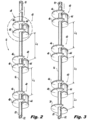
- the soil displacement pile 10 has a lead 12 and possibly one or more extensions 14.
- the lead 12 comprises a square or round shaft or pipe 16 and at least one soil displacement assembly 40.
- the lead shaft 16, which is the bottom most shaft of a soil displacement pile 10 has a lead head portion 18 and a lead end portion 20.
- the lead end portion 20 is configured to first penetrate the soil, and terminates at its distal end with a tapered tip 22.
- Each of the one or more extensions 14 comprises a square or round shaft or pipe 24 and at least one soil displacement assembly 40.
- Each extension shaft 24 has extension head portion 26 and an extension end portion 28.
- the first extension added to the soil displacement pile 10 is secured to the lead 12 where the extension end portion 28 is mated with the lead head portion 18 using one or more nut and bolt. Subsequent extensions may be sequentially joined together where the extension end portion 28 of the next in line extension 14 is mated with the extension head portion 26 of the previous extension 14 using one or more nut and bolt.
- the lead shaft 16 and the extension shaft 24 can be hollow or solid, and the shafts 16 and 24 can be made of metal, e.g., steel or galvanized steel, or carbon fiber, or other suitable material known in the art.
- the extensions 14 are optional such that the lead 12 may comprise the soil displacement pile 10 and a pile drive system head is used to rotate the lead 12 into the soil. If one or more extensions 14 are added to the lead 12 then the lead and the one or more extensions form the soil displacement pile 10, and the pile drive system head is used to first rotate the lead 12 into the soil and then each extension successively into the soil.
- the lead 12 and extensions 14 include one or more soil displacement assemblies 40 secured directly or indirectly to the lead shaft 16 and/or the extension shaft 24.
- Securing the soil displacement assemblies 40 directly to the lead shaft 16 and/or the extension shaft 24 includes a direct connection between the respective shaft and the soil displacement assembly, such as by welding or mechanical fasteners.
- Securing the soil displacement assemblies 40 indirectly to the lead shaft 16 and/or the extension shaft 24 includes an indirect connection between the respective shaft and the soil displacement assembly, such as by using a coupler to join the respective shaft and the soil displacement assembly and securing the coupler to the shaft, or by mating the soil displacement assembly with a coupling already on the respective shaft.
- a coupler to join the respective shaft and the soil displacement assembly and securing the coupler to the shaft
- the lead 12 has one soil displacement assembly 40 and the extension 14 has one soil displacement assembly 40.
- the lead 12 has three soil displacement assemblies 40 spaced along the length of the shaft with a longitudinal distance "Ls" between each soil displacement assembly. The longitudinal distance “Ls” between the soil displacement assemblies may be in the range from about 3 feet to about 10 feet.
- the lead 12 has three soil displacement assemblies 40 spaced along the length of the shaft with a longitudinal distance "Ls” between each soil displacement assembly, and also includes one or more spaced apart load bearing helical plates 30 arranged on the lead shaft 16. The load bearing helical plate 30 is typically in the lead end portion 20 and separated from the lower soil displacement assembly 40 a distance "Lt".
- the spacing "Lt" between the load bearing helical plate 30 and the lower soil displacement assembly 40 may range from about 30.5 cm (12 inches) to about 61 cm (24 inches).
- the load bearing helical plate 30 is provided to initially penetrate the soil and pull the soil displacement pile 10 downward when the lead shaft 16 is rotated.
- the lead 12 has a single load bearing helical plate 30.
- the load bearing helical plates 30 may have the same diameter, or the load bearing helical plates 30 may have different diameters that are in, for example, a tapered arrangement.
- the smallest diameter load bearing helical plate 30 may be positioned closest to the tapered tip 22 of the lead shaft 16, and the largest load bearing helical plate 30 may be positioned at a distance away from the tapered tip 22.
- Such load bearing helical plates 30 on the lead shaft 16 may be spaced apart at a distance sufficient to promote plate load bearing capacity as is known in the art.
- the diameter of the load bearing helical plates 30 may range from between about 15.2 cm (6 inches) to about 40.6 cm (16 inches) depending upon the load the soil displacement pile 10 is to carry.
- the pitch of the load bearing helical plates is between about 5.1 cm (2 inches) and about 10.1 cm (4 inches). For example, the pitch may be about 7.6 cm (3 inches).
- the soil displacement assembly 40 includes, for example, a pair of helical plates 42 and at least one soil displacement plate 44.
- Each helical plate pair 42 comprises an upper helical plate 46 and a lower helical plate 48.
- the upper and lower helical plates 46 and 48 are separated by a longitudinal distance "Lp" creating a void 60 between the upper and lower helical plates.
- the distance "Lp” is based upon, for example, the helix pitch and diameter.
- the distance “Lp” can range from between about 15.2 cm (6 inches) to about 30.5 cm (12 inches).
- the longitudinal distance between the soil displacement assemblies "Ls" is greater than the longitudinal distance between the helical plate pair "Lp".
- the diameter "D" of the upper and lower helical plates 46 and 48 may range from between about 15.2 cm (6 inches) to about 40.6 cm (16 inches) depending upon the size of the cavity to be created by soil displacing assembly 40 and thus the size of the pile column created by the cured filler and soil displacement pile 10.
- the diameter "D" of the upper and lower helical plates 46 and 48 may be the same, as shown in Fig. 4 , or they may differ, as shown in Fig. 11 . More specifically, the upper helical plate 46 may have a diameter that is larger than the lower helical plate 48, or the upper helical plate 46 may have a diameter that is smaller than the lower helical plate 48.
- the diameter of the upper helical plate 46 may be about 40.6cm (16 inches) and the diameter of the lower helical plate 48 may be 15.2 cm (6 inches).
- the diameter of the upper helical plate 46 may be about 20.3 cm (8 inches) and the diameter of the lower helical plate 48 may be 30.5 cm (12 inches).
- the upper and lower helical plates 46 and 48 have a helical pitch "P" of between about 5.1 cm (2 inches) and about 10.2 cm (4 inches).
- the pitch may be about 7.6 cm (3 inches).
- the pitch of the upper and lower helical plates 46 and 48 creates a gap 62 between the leading edge of each plate and the trailing edge of each plate.
- This gap 62 permits filler being poured into the cavity 70, seen in Fig. 14 , created by the one or more soil displacement assemblies 40 to fill the void 60 between the upper and lower helical plates 46 and 48, and to permit filler to pass through the soil displacement assembly.
- the thickness "T" of each helical plate 46 and 48 may be between about 1.0 cm (3/8 inch) and about 1.9 cm (3/4 inch).
- one soil displacement plate 44 is positioned between the helical plates 46 and 48 and secured to the shaft 16 of the lead 12 or the shaft 24 of the extension 14 by, for example, welding or mechanical fasteners.
- the soil displacement plate 44 is also attached to each of the upper and lower helical plates 46 and 48 by, for example, welding or mechanical fasteners. Attaching the soil displacement plate 44 between the upper and lower helical plates 46 and 48 increases the strength of the soil displacement plate 44 facilitating displacement of the soil as described herein.
- Each soil displacement plate 44 has a soil contacting surface 45, and extends radially from the shaft 16 of the lead 12 or the shaft 24 of the extension 14 to an outer edge of each helical plate.
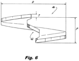
- each soil displacement plate 44 is a curved plate, as shown in Fig. 5 , and is secured to the helical plates 46 and 48 so that the soil displacement plate curves in a counterclockwise direction proceeding radially from the shaft 16 of the lead 12 or the shaft 24 of the extension 14 such that the soil contacting surface 45, here the convex surface, of the soil displacement plate 44 is positioned to contact and displace the soil to create the cavity 70 for forming the pile column 80.
- the convex surface 45 of the soil displacement plate 44 contacts the soil and displaces it radially outward away from the shaft 16 of the lead 12 or away from the shaft 24 of the extension 14 creating the displaced soil cavity 70.
- the soil displacement plate 44 may be secured to the lead shaft 12 or extension shaft 14 and the helical plates 46 and 48 anywhere along the helical plates. In the configuration shown in Figs. 4 and 5 , one end of the soil displacement plate 44 is positioned adjacent a leading edge 50 of the upper helical plate 46 and adjacent a leading edge 50 of the lower helical plate 48.
- the soil displacement plate 44 is illustrated in Figs. 4 and 5 as having a soil contacting surface 45 over a relatively small circumferential portion of the upper and lower helical plates 46 and 48. However, the soil displacement plate 44 may have a soil contacting surface 45 that extends along a more substantial portion of the circumference of the upper and lower helical plates 46 and 48.
- the radius of the curvature of the soil displacement plate 44 may vary depending upon, for example, the type of soil to be encountered and the relative density of the soil to be encountered.
- the radius of the curvature of the soil displacement plate 44 may be in the range of about 30 degrees to about 180 degrees.
- the soil contacting surface 45 may vary and may be irregular so long as the soil contacting surface 45 is capable of displacing soil outwardly as the soil displacement pile 10 is being rotated.
- the vertical orientation of the soil displacement plate 44 may vary depending upon a number of considerations such as the location along the helical plates and the radius of curvature.
- the soil displacement plate 44 is secured to the helical plates 46 and 48 so that the soil displacement plate is substantially vertical relative to the shaft 16 of the lead 12 or the shaft 24 of the extension 14.
- the soil displacement plate 44 may be angled or tilted relative to the shaft 16 of the lead 12 or the shaft 24 of the extension 14.
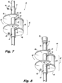
- the soil displacement assembly 40 includes coupling tube 41, a pair of helical plates 42 and at least one soil displacement plate 44.
- the coupling tube 41 is configured to fit over shaft 16 of the lead 12 or the shaft 24 of the extension 14, and can be secured to the shaft 16 or 24 via a mechanical fastener, such as a set screw 43 and threaded aperture 47, that are threaded into matching threaded apertures in the respective shaft 16 or 24.
- a mechanical fastener such as a set screw 43 and threaded aperture 47, that are threaded into matching threaded apertures in the respective shaft 16 or 24.
- the set screw 43 when tightened in the threaded aperture 47 on the respective shaft 16 or 24 can create a friction force between the coupling tube 41 and the shaft thus binding the soil displacement assembly 40 in position on the shaft.
- Each helical plate pair 42 comprises an upper helical plate 46 and a lower helical plate 48.
- the upper and lower helical plates 46 and 48 are secured to the coupling tube 41 by for example welding the plates to the coupling tube.
- the upper and lower helical plates 46 and 48 are separated by a longitudinal distance "Lp" creating a void 60 between the upper and lower helical plates.
- Positioned between the upper and lower helical plates 46 and 48 is the at least one soil displacement plate 44, as described above and for the ease of description is not repeated.
- the soil displacement assembly can be secured to existing helical piles to form the soil displacement pile 10 of the present disclosure.
- the soil displacement assembly 40 includes coupling tube 41, a pair of helical plates 42 and at least one soil displacement plate 44.
- the coupling tube 41 is configured to fit over shaft 16 of the lead 12 or the shaft 24 of the extension 14, and a coupling 19 at a top of the shaft 16 of the lead 12 or the shaft 24 of the extension 14 prevents the coupling tube 41 from separating from the shaft when the lead 16 or extension 24 is being inserted into the ground.
- each helical plate pair 42 comprises an upper helical plate 46 and a lower helical plate 48.
- the upper and lower helical plates 46 and 48 are secured to the coupling tube 41 by for example welding the plates to the coupling tube.
- the upper and lower helical plates 46 and 48 are separated by a longitudinal distance "Lp" creating a void 60 between the upper and lower helical plates.
- the soil displacement assembly can be secured to existing helical piles to form the soil displacement pile 10 of the present disclosure.
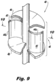
- the soil displacement assembly 40 includes two helical plates forming a pair 42 and a pair of soil displacement plates 44a and 44b.
- the helical plate pair 42 comprises an upper helical plate 46 and a lower helical plate 48 which are described above and for the ease of description are not repeated.
- the first soil displacement plate 44a is positioned the same as the soil displacement plate shown in the configuration of Figs. 4 and 5 .
- the second soil displacement plate 44b is also attached between the helical plates 46 and 48 and oriented the same as the first soil displacement plate 44a as shown.
- the second soil displacement plate 44b is attached to the helical plates at an angular distance " ⁇ " from the first soil displacement plate 44a as shown in Fig. 10 .
- the angular distance " ⁇ ” may be from about 60 degrees to about 180 degrees.
- the angular distance " ⁇ ” may be 180 degrees.
- Fig. 11 illustrates another exemplary configuration of the soil displacement assembly according to the present disclosure.
- the soil displacement assembly 40 comprises a helical plate pair 42 where the diameter of the upper helical plate 46 and the diameter of the lower helical plate 48 differ.
- the upper helical plate 46 has a larger diameter than the lower helical plate 48.
- the upper helical plate 46 can have a smaller diameter than the lower helical plate 48.
- the soil displacement plate 44 is attached between the upper helical plate 46 and the lower helical plate 48.
- the different diameter between the upper and lower helical plates 46 and 48 facilitates the displacement of soil and the pulling of the soil displacement pile 10 into the ground because the distance "R" between an outer edge of the larger diameter helical plate, here plate 46, and the soil displacement plate 44 permits more of the helical plate 46 to grip the soil.
- Figs. 12 and 13 illustrate another exemplary configuration of the soil displacement assembly 40 according to the present disclosure.
- the soil displacement assembly 40 includes two helical plates forming a pair 42 and a pair of soil displacement plates 44a and 44b.
- the helical plate pair 42 comprises an upper helical plate 46 and a lower helical plate 48 which are described above and for the ease of description are not repeated.
- the first soil displacement plate 44a is positioned the same as in, for example, the configurations of Figs. 4, 5 and 6 .
- the second soil displacement plate 44b is attached to the upper helical plate 46 and the shaft 16 of the lead 12 or the shaft 24 of the extension 14 near the trailing edge 54 of the upper helical plate 46.
- the second soil displacement plate 44b provides additional soil displacement further facilitating the formation of the cavity 70 in which the pile column 80, seen in Fig. 14 , is formed.
- Figs. 14 and 15 an example of the insertion of a lead 12 into the ground and the pouring of filler into the cavity created by the soil displacement assembly of the present disclosure will be described.
- the leading edge 52 and outer edge of the lower helical plate 48 grips the soil to start pulling the lead 12 into the ground.
- the soil contacting surface 45 of the soil displacement plate 44 displaces the soil cut by the leading edge 52 and outer edge of the lower helical plate 48 radially outwardly away from a shaft 16 of the lead 12 to begin to form a cavity 70 in which filler is poured.
- the leading edge 50 and outer edge of the upper helical plate 46 then grips the soil to assist in pulling the lead 12 into the ground.
- the upper helical plate 46 also helps to mix any loose residual soil within the cavity 70 with the filler.
- the gap 62 in the helical plates 46 and 48 permits the filler being poured into the cavity to fill the void 60 between the upper and lower helical plates, and permits the filler to pass through the soil displacement assembly 40 to provide a uniform pour of the filler.
- the leading edge 52 and outer edge of the lower helical plate 48 grips the soil to assist in pulling the lead 12 into the ground.
- the leading edge 50 and outer edge of the upper helical plate 46 then grips the soil to assist in pulling the lead 12 into the ground.
- the upper helical plate 46 also helps to mix any loose residual soil within the cavity 70 with the filler.
- the gap 62 in the helical plates 46 and 48 permits the filler being poured into the cavity to fill the void 60 between the upper and lower helical plates 46 and 48 of the second soil displacement assembly 40, and to permit the filler pass through the soil displacement assembly to provide a uniform pour of the filler.
- the leading edge 52 and outer edge of the lower helical plate 48 grips the soil to assist in pulling the lead 12 into the ground.
- the leading edge 50 and outer edge of the upper helical plate 46 then grips the soil to assist in pulling the lead 12 into the ground.
- the upper helical plate 46 also helps to mix any loose residual soil within the cavity with the filler.
- the gap 62 in the helical plates 46 and 48 permits filler being poured into the cavity to fill the void 60 between the upper and lower helical plates 46 and 48 of the third soil displacement assembly 40, and permits the filler to pass through the soil displacement assembly to provide a uniform pour of the filler.
- the filler with the embedded pile 10 form a composite pile column 80.
- the present disclosure describes a way of displacing soil for the purpose of creating a pile column with an embedded soil displacement pile.
- the one or more helical soil displacement assemblies displace soil so that filler may be poured into a cavity created by the one or more soil displacement assemblies around the soil displacement pile forming a pile column at the job site.
- the soil displacement assembly of the present disclosure permits the use of larger diameter shafts and helical plates for the lead and/or extensions which facilitates displacement of more soil and results in the formation of pile columns having larger diameters and therefore improved load capacity.
- the helical plate pairs can be placed close together with one or more soil displacement plates connected between the helical plate pairs.
- the helical plates help loosen the soil and provide strength to keep the soil displacement plate in position when screwing the soil displacement pile into the ground.
- the soil displacement pile of the present disclosure can displace a greater volume of soil to create larger pile columns.
- the lead shaft and extension shafts and helical plates provide additional stiffening to the soil displacement assemblies while the filler provides the larger diameter, skin friction, and higher load capacities.
- the soil displacement pile and soil displacement assembly of the present disclosure can be adapted to form any size pile column needed for a particular job.
- the soil displacement pile and soil displacement assembly of the present disclosure can easily form pile columns that are greater than 20.3 cm (eight inches) in diameter.
Landscapes
- Engineering & Computer Science (AREA)
- Structural Engineering (AREA)
- Life Sciences & Earth Sciences (AREA)
- General Life Sciences & Earth Sciences (AREA)
- Mining & Mineral Resources (AREA)
- Paleontology (AREA)
- Civil Engineering (AREA)
- General Engineering & Computer Science (AREA)
- Piles And Underground Anchors (AREA)
- Bulkheads Adapted To Foundation Construction (AREA)
- Mechanical Coupling Of Light Guides (AREA)
- Slot Machines And Peripheral Devices (AREA)
- Sliding Valves (AREA)
Claims (15)
- Bodenverdrängungspfahl (10) zum Ausbilden einer Verbundpfahlsäule, der Bodenverdrängungspfahl umfassend:eine Leitung (12), umfassend:einen Leitungsschaft (16); undmindestens eine Leitungsbodenverdrängungsbaugruppe (40), die mindestens teilweise an dem Leitungsschaft angebracht ist, wobei die mindestens eine Leitungsbodenverdrängungsbaugruppe einschließt;eine obere Spiralplatte (46), die einen äußeren Randabschnitt und eine zentrale Öffnung aufweist, die einen inneren Randabschnitt definiert;eine untere Spiralplatte (48), die einen äußeren Randabschnitt und eine zentrale Öffnung aufweist, die einen inneren Randabschnitt definiert, wobei die untere Spiralplatte in einem vordefinierten Abstand von der oberen Spiralplatte (46) entlang einer Längsachse der Bodenverdrängungsbaugruppe (40) beabstandet ist; undeine gekrümmte Bodenverdrängungsplatte (44), die einen ersten Randabschnitt, der an der oberen Spiralplatte (46) angebracht ist, und einen zweiten Randabschnitt aufweist, der an der unteren Spiralplatte (48) derart angebracht ist, dass eine konvexe Oberfläche der gekrümmten Bodenverdrängungsplatte, die eine Bodenkontaktoberfläche ausbildet, sich von den inneren Randabschnitten der oberen Spiralplatte (46) und der unteren Spiralplatte (48) zu den äußeren Randabschnitten der oberen Spiralplatte (46) und der unteren Spiralplatte erstreckt, und derart, dass die konvexe Oberfläche ausgerichtet ist, um mit Boden in Kontakt zu kommen, wenn die Bodenverdrängungsbaugruppe (40) in den Boden getrieben wird, um den Boden von den inneren Randabschnitten der oberen Spiralplatte (46) und der unteren Spiralplatte (48) zu den äußeren Randabschnitten der oberen Spiralplatte und der unteren Spiralplatte hin zu verschieben, um einen Hohlraum in dem Boden zu erzeugen; undmindestens eine Verlängerung (14), umfassend:ein Verlängerungsschaft (24); undmindestens eine Verlängerungsbodenverdrängungsbaugruppe (40), die an der Verlängerungswelle angebracht ist.
- Bodenverdrängungspfahl nach Anspruch 1, wobei die mindestens eine Bodenverdrängungsplatte im Wesentlichen senkrecht zu der oberen Spiralplatte und der unteren Spiralplatte steht.
- Bodenverdrängungspfahl nach Anspruch 1, wobei die mindestens eine Bodenverdrängungsplatte in einem Winkel relativ zu der oberen Spiralplatte und der unteren Spiralplatte positioniert ist.
- Bodenverdrängungspfahl nach Anspruch 1, wobei die obere Spiralplatte einen Durchmesser in dem Bereich zwischen etwa 15,2 cm (6 Zoll) und etwa 40,6 cm (16 Zoll) aufweist.
- Bodenverdrängungspfahl nach Anspruch 1, wobei die untere Spiralplatte einen Durchmesser in dem Bereich zwischen etwa 15,2 cm (6 Zoll) und etwa 40,6 cm (16 Zoll) aufweist.
- Bodenverdrängungspfahl nach Anspruch 1, wobei ein Durchmesser der oberen Spiralplatte größer als ein Durchmesser der unteren Spiralplatte ist.
- Bodenverdrängungspfahl nach Anspruch 1, wobei ein Durchmesser der oberen Spiralplatte kleiner als ein Durchmesser der unteren Spiralplatte ist.
- Bodenverdrängungspfahl nach Anspruch 1, wobei die mindestens eine Bodenverdrängungsplatte mindestens eine obere Bodenverdrängungsplatte umfasst, die auf der oberen Spiralplatte positioniert ist.
Applications Claiming Priority (2)
| Application Number | Priority Date | Filing Date | Title |
|---|---|---|---|
| US201662290637P | 2016-02-03 | 2016-02-03 | |
| PCT/US2016/061010 WO2017136013A1 (en) | 2016-02-03 | 2016-11-08 | Soil displacement piles |
Publications (3)
| Publication Number | Publication Date |
|---|---|
| EP3411528A1 EP3411528A1 (de) | 2018-12-12 |
| EP3411528A4 EP3411528A4 (de) | 2019-10-09 |
| EP3411528B1 true EP3411528B1 (de) | 2025-01-22 |
Family
ID=59385452
Family Applications (1)
| Application Number | Title | Priority Date | Filing Date |
|---|---|---|---|
| EP16889641.3A Active EP3411528B1 (de) | 2016-02-03 | 2016-11-08 | Bodenverdrängungspfähle |
Country Status (6)
| Country | Link |
|---|---|
| US (2) | US10458090B2 (de) |
| EP (1) | EP3411528B1 (de) |
| CA (1) | CA3013306C (de) |
| CL (1) | CL2018002098A1 (de) |
| MX (1) | MX2018009349A (de) |
| WO (1) | WO2017136013A1 (de) |
Families Citing this family (13)
| Publication number | Priority date | Publication date | Assignee | Title |
|---|---|---|---|---|
| US10077893B1 (en) * | 2013-02-11 | 2018-09-18 | Philip Abraham | Removable anchoring system and uses thereof |
| JP5842046B1 (ja) * | 2014-10-21 | 2016-01-13 | 新日鉄住金エンジニアリング株式会社 | 回転圧入鋼管杭 |
| US12428832B2 (en) * | 2016-10-06 | 2025-09-30 | NXT Building System Pty. Ltd. | Building system |
| US10563370B2 (en) * | 2017-05-01 | 2020-02-18 | Terra Sonic International, LLC | Bolting adapter mechanism for sonic pile driving |
| WO2019090116A1 (en) * | 2017-11-04 | 2019-05-09 | Hubbell Incorporated | Helical pile with heat exchanger |
| US10767334B2 (en) * | 2018-03-02 | 2020-09-08 | Magnum Piering, Inc. | Grouted helical pile |
| US10615739B2 (en) * | 2018-09-05 | 2020-04-07 | Ojjo, Inc. | Optimized truss foundations, adapters for optimized truss foundations, and related systems and methods |
| US11536001B2 (en) * | 2019-02-05 | 2022-12-27 | Ojjo, Inc. | Truss foundations with improved corrosion resistance and related systems, methods and machines |
| US12221762B2 (en) * | 2019-05-22 | 2025-02-11 | Benjamin G. Stroyer | Displacement pile and pile driver adapter |
| US11708678B2 (en) | 2019-12-18 | 2023-07-25 | Cyntech Anchors Ltd | Systems and methods for supporting a structure upon compressible soil |
| CN111519608B (zh) * | 2020-04-28 | 2021-08-31 | 中一达建设集团有限公司 | 一种可快速接桩的抗拔桩 |
| MX2024002470A (es) | 2021-08-31 | 2024-08-26 | Geopier Found Co Inc | Un sistema y un método para instalar un pilar de áridos. |
| CN115030213B (zh) * | 2022-05-26 | 2023-04-11 | 上海勘测设计研究院有限公司 | 一种适用于海上风电基桩的工装以及应用方法 |
Family Cites Families (34)
| Publication number | Priority date | Publication date | Assignee | Title |
|---|---|---|---|---|
| US153807A (en) * | 1874-08-04 | Improvement in earth-augers | ||
| US2613062A (en) * | 1950-12-20 | 1952-10-07 | Carl M Harbert | Earth drilling bit |
| US3382937A (en) * | 1966-05-02 | 1968-05-14 | James P. Watts | Drilling auger |
| DE3314125A1 (de) | 1983-04-19 | 1984-10-25 | Jean Remilly-Aillicourt Bertrand | Vorrichtung zum verankern, insbesondere bodenanker |
| NL189365C (nl) | 1984-04-09 | 1993-03-16 | Fundex Naamloze Vennootschap | Grondverdringingsboor, alsmede werkwijze voor het vormen van een fundatiepaal in de grond onder toepassing van die grondverdringingsboor. |
| US5252009A (en) | 1991-01-22 | 1993-10-12 | Joseph Bossler | Industrial and roadway identification and floor surface treatment system, and diamond surface drill bit for use in installing the system |
| JP3435607B2 (ja) | 1992-05-01 | 2003-08-11 | 株式会社村田製作所 | 非還元性誘電体磁器組成物 |
| BE1007558A5 (nl) | 1993-10-28 | 1995-08-01 | Hareninvest | Grondverdringingsboorkop voor het vormen van palen in de grond. |
| US5707180A (en) | 1995-12-26 | 1998-01-13 | Vickars Developments Co. Ltd. | Method and apparatus for forming piles in-situ |
| US6264402B1 (en) * | 1995-12-26 | 2001-07-24 | Vickars Developments Co. Ltd. | Method and apparatus for forming piles in place |
| DE19702137A1 (de) | 1997-01-22 | 1998-07-23 | Fundex N V | Erdverdrängungsbohrer |
| JP2001040662A (ja) | 1999-07-29 | 2001-02-13 | Maeda Seikan Kk | コンクリート杭及びその埋設工法 |
| US7494299B1 (en) | 2000-11-14 | 2009-02-24 | Michael Whitsett | Piling apparatus having rotary drive |
| US6722821B1 (en) * | 2002-01-04 | 2004-04-20 | Howard A. Perko | Helice pier post and method of installation |
| AU2003257241B2 (en) | 2002-09-02 | 2004-10-21 | Colin William Francis | A pier |
| US6834733B1 (en) | 2002-09-04 | 2004-12-28 | Varel International, Ltd. | Spiral wave bladed drag bit |
| DE10308540B4 (de) | 2003-02-27 | 2005-02-17 | Bauer Maschinen Gmbh | Verfahren und Vorrichtung zum Herstellen eines Gründungselementes |
| US7198434B2 (en) * | 2004-07-13 | 2007-04-03 | Berkel & Company Contractors, Inc. | Full-displacement pressure grouted pile system and method |
| US7357394B2 (en) * | 2004-10-01 | 2008-04-15 | Sri Acquisition Corp. | Modular shooting range |
| US20080302028A1 (en) | 2005-09-20 | 2008-12-11 | Stephen Mark Lewenhoff | Ground Anchor |
| DE502006001030D1 (de) | 2006-04-26 | 2008-08-14 | Bauer Maschinen Gmbh | Bohrspitze |
| US7748932B2 (en) | 2006-06-09 | 2010-07-06 | Russell Lindsey | Soil stabilization and anchorage system |
| US8033757B2 (en) * | 2006-09-08 | 2011-10-11 | Ben Stroyer | Auger grouted displacement pile |
| US8926228B2 (en) | 2006-09-08 | 2015-01-06 | Ben Stroyer | Auger grouted displacement pile |
| US7854451B2 (en) * | 2007-01-03 | 2010-12-21 | Davis Ii Joseph S | Anchor pile coupling system |
| JP4961448B2 (ja) | 2009-03-24 | 2012-06-27 | 新日鉄エンジニアリング株式会社 | 基礎杭の先端部材及びこれを用いた基礎杭 |
| IT1394001B1 (it) * | 2009-04-20 | 2012-05-17 | Soilmec Spa | Attrezzatura di scavo e costipazione per la costruzione di pali a vite. |
| JP5546000B2 (ja) * | 2010-09-27 | 2014-07-09 | 旭化成建材株式会社 | 地盤の掘削方法 |
| JP5435499B2 (ja) | 2010-10-04 | 2014-03-05 | 日鉄住金物産株式会社 | 鋼管杭の連結構造 |
| US9115478B2 (en) * | 2011-10-25 | 2015-08-25 | Hubbell Incorporated | Helical screw pile |
| US20130343823A1 (en) | 2012-05-04 | 2013-12-26 | Wei-Chung Lin | Pile with Grout Vortex |
| US8845236B1 (en) * | 2013-02-15 | 2014-09-30 | FixDirt, LLC | Ground anchor |
| US9416513B2 (en) | 2013-10-25 | 2016-08-16 | Hubbell Incorporated | Helical screw pile and soil displacement device with curved blades |
| US9422741B1 (en) * | 2014-05-09 | 2016-08-23 | Matthew A. Conte | Ball field suspended fence post base support and post support with lateral support |
-
2016
- 2016-11-08 EP EP16889641.3A patent/EP3411528B1/de active Active
- 2016-11-08 MX MX2018009349A patent/MX2018009349A/es unknown
- 2016-11-08 WO PCT/US2016/061010 patent/WO2017136013A1/en not_active Ceased
- 2016-11-08 CA CA3013306A patent/CA3013306C/en active Active
- 2016-11-08 US US15/346,672 patent/US10458090B2/en active Active
-
2018
- 2018-08-03 CL CL2018002098A patent/CL2018002098A1/es unknown
-
2019
- 2019-10-18 US US16/657,264 patent/US10865539B2/en active Active
Also Published As
| Publication number | Publication date |
|---|---|
| CA3013306C (en) | 2022-09-20 |
| CL2018002098A1 (es) | 2018-11-23 |
| US20200048855A1 (en) | 2020-02-13 |
| CA3013306A1 (en) | 2017-08-10 |
| EP3411528A1 (de) | 2018-12-12 |
| US20170218590A1 (en) | 2017-08-03 |
| US10865539B2 (en) | 2020-12-15 |
| US10458090B2 (en) | 2019-10-29 |
| WO2017136013A1 (en) | 2017-08-10 |
| MX2018009349A (es) | 2018-09-21 |
| EP3411528A4 (de) | 2019-10-09 |
Similar Documents
| Publication | Publication Date | Title |
|---|---|---|
| US10865539B2 (en) | Soil displacement piles | |
| US10392768B2 (en) | Pile with soil displacement assembly | |
| US10947688B2 (en) | Grout propeller for helical pile | |
| US4239419A (en) | Precast concrete threaded pilings | |
| CN101970777B (zh) | 自攻地基桩 | |
| US20200385947A1 (en) | Pile coupling for helical pile/torqued in pile | |
| US9416513B2 (en) | Helical screw pile and soil displacement device with curved blades | |
| KR102195847B1 (ko) | 나선판을 갖는 파일 결합구조 | |
| US20150368870A1 (en) | Helical screw pile | |
| US9057169B1 (en) | Sacrificial tip and method of installing a friction pile | |
| GB1595432A (en) | Precast concrete piling | |
| JP3169245U (ja) | 継手装置 | |
| KR200480999Y1 (ko) | 강관 파일의 회전 관입 및 인발용 커플러 | |
| JP5415218B2 (ja) | 鋼管杭 | |
| KR101598339B1 (ko) | 데크플레이트 결합용 체결구 | |
| KR101939020B1 (ko) | 기초 배근 연결용 지압유닛 및 이를 적용한 강관 파일의 기초 공법 | |
| JP6007863B2 (ja) | 回転杭を構成する鋼管の接合構造 | |
| KR101759879B1 (ko) | 회전 관입 말뚝 유니트, 회전 관입 말뚝 및 이의 시공 방법 | |
| KR101712649B1 (ko) | 스크류 파일 설치 기구 | |
| US20240318399A1 (en) | Soil displacement pile assembly and method of forming foundation pile | |
| KR200481009Y1 (ko) | 강관 파일의 회전 관입 및 인발용 커플러 | |
| GB2426777A (en) | A pile sleeve | |
| AU2487601A (en) | Anchor elements and methods and apparatus for fabricating anchor elements | |
| JP2006132243A (ja) | コンクリート杭及びそれを使用した基礎用杭、基礎用杭の建込方法 |
Legal Events
| Date | Code | Title | Description |
|---|---|---|---|
| STAA | Information on the status of an ep patent application or granted ep patent |
Free format text: STATUS: THE INTERNATIONAL PUBLICATION HAS BEEN MADE |
|
| PUAI | Public reference made under article 153(3) epc to a published international application that has entered the european phase |
Free format text: ORIGINAL CODE: 0009012 |
|
| STAA | Information on the status of an ep patent application or granted ep patent |
Free format text: STATUS: REQUEST FOR EXAMINATION WAS MADE |
|
| 17P | Request for examination filed |
Effective date: 20180801 |
|
| AK | Designated contracting states |
Kind code of ref document: A1 Designated state(s): AL AT BE BG CH CY CZ DE DK EE ES FI FR GB GR HR HU IE IS IT LI LT LU LV MC MK MT NL NO PL PT RO RS SE SI SK SM TR |
|
| AX | Request for extension of the european patent |
Extension state: BA ME |
|
| DAV | Request for validation of the european patent (deleted) | ||
| DAX | Request for extension of the european patent (deleted) | ||
| A4 | Supplementary search report drawn up and despatched |
Effective date: 20190911 |
|
| RIC1 | Information provided on ipc code assigned before grant |
Ipc: E02D 5/56 20060101AFI20190905BHEP Ipc: E02D 5/34 20060101ALI20190905BHEP Ipc: E02D 5/48 20060101ALI20190905BHEP |
|
| STAA | Information on the status of an ep patent application or granted ep patent |
Free format text: STATUS: EXAMINATION IS IN PROGRESS |
|
| 17Q | First examination report despatched |
Effective date: 20220222 |
|
| GRAP | Despatch of communication of intention to grant a patent |
Free format text: ORIGINAL CODE: EPIDOSNIGR1 |
|
| STAA | Information on the status of an ep patent application or granted ep patent |
Free format text: STATUS: GRANT OF PATENT IS INTENDED |
|
| INTG | Intention to grant announced |
Effective date: 20240812 |
|
| GRAS | Grant fee paid |
Free format text: ORIGINAL CODE: EPIDOSNIGR3 |
|
| GRAA | (expected) grant |
Free format text: ORIGINAL CODE: 0009210 |
|
| STAA | Information on the status of an ep patent application or granted ep patent |
Free format text: STATUS: THE PATENT HAS BEEN GRANTED |
|
| AK | Designated contracting states |
Kind code of ref document: B1 Designated state(s): AL AT BE BG CH CY CZ DE DK EE ES FI FR GB GR HR HU IE IS IT LI LT LU LV MC MK MT NL NO PL PT RO RS SE SI SK SM TR |
|
| REG | Reference to a national code |
Ref country code: GB Ref legal event code: FG4D |
|
| REG | Reference to a national code |
Ref country code: CH Ref legal event code: EP |
|
| REG | Reference to a national code |
Ref country code: IE Ref legal event code: FG4D |
|
| REG | Reference to a national code |
Ref country code: DE Ref legal event code: R096 Ref document number: 602016091046 Country of ref document: DE |
|
| REG | Reference to a national code |
Ref country code: NL Ref legal event code: MP Effective date: 20250122 |
|
| PG25 | Lapsed in a contracting state [announced via postgrant information from national office to epo] |
Ref country code: NL Free format text: LAPSE BECAUSE OF FAILURE TO SUBMIT A TRANSLATION OF THE DESCRIPTION OR TO PAY THE FEE WITHIN THE PRESCRIBED TIME-LIMIT Effective date: 20250122 |
|
| PG25 | Lapsed in a contracting state [announced via postgrant information from national office to epo] |
Ref country code: RS Free format text: LAPSE BECAUSE OF FAILURE TO SUBMIT A TRANSLATION OF THE DESCRIPTION OR TO PAY THE FEE WITHIN THE PRESCRIBED TIME-LIMIT Effective date: 20250422 |
|
| PG25 | Lapsed in a contracting state [announced via postgrant information from national office to epo] |
Ref country code: FI Free format text: LAPSE BECAUSE OF FAILURE TO SUBMIT A TRANSLATION OF THE DESCRIPTION OR TO PAY THE FEE WITHIN THE PRESCRIBED TIME-LIMIT Effective date: 20250122 |
|
| PG25 | Lapsed in a contracting state [announced via postgrant information from national office to epo] |
Ref country code: PL Free format text: LAPSE BECAUSE OF FAILURE TO SUBMIT A TRANSLATION OF THE DESCRIPTION OR TO PAY THE FEE WITHIN THE PRESCRIBED TIME-LIMIT Effective date: 20250122 |
|
| PG25 | Lapsed in a contracting state [announced via postgrant information from national office to epo] |
Ref country code: ES Free format text: LAPSE BECAUSE OF FAILURE TO SUBMIT A TRANSLATION OF THE DESCRIPTION OR TO PAY THE FEE WITHIN THE PRESCRIBED TIME-LIMIT Effective date: 20250122 |
|
| REG | Reference to a national code |
Ref country code: LT Ref legal event code: MG9D |
|
| PG25 | Lapsed in a contracting state [announced via postgrant information from national office to epo] |
Ref country code: IS Free format text: LAPSE BECAUSE OF FAILURE TO SUBMIT A TRANSLATION OF THE DESCRIPTION OR TO PAY THE FEE WITHIN THE PRESCRIBED TIME-LIMIT Effective date: 20250522 Ref country code: NO Free format text: LAPSE BECAUSE OF FAILURE TO SUBMIT A TRANSLATION OF THE DESCRIPTION OR TO PAY THE FEE WITHIN THE PRESCRIBED TIME-LIMIT Effective date: 20250422 |
|
| REG | Reference to a national code |
Ref country code: AT Ref legal event code: MK05 Ref document number: 1761563 Country of ref document: AT Kind code of ref document: T Effective date: 20250122 |
|
| PG25 | Lapsed in a contracting state [announced via postgrant information from national office to epo] |
Ref country code: HR Free format text: LAPSE BECAUSE OF FAILURE TO SUBMIT A TRANSLATION OF THE DESCRIPTION OR TO PAY THE FEE WITHIN THE PRESCRIBED TIME-LIMIT Effective date: 20250122 |
|
| PG25 | Lapsed in a contracting state [announced via postgrant information from national office to epo] |
Ref country code: LV Free format text: LAPSE BECAUSE OF FAILURE TO SUBMIT A TRANSLATION OF THE DESCRIPTION OR TO PAY THE FEE WITHIN THE PRESCRIBED TIME-LIMIT Effective date: 20250122 Ref country code: PT Free format text: LAPSE BECAUSE OF FAILURE TO SUBMIT A TRANSLATION OF THE DESCRIPTION OR TO PAY THE FEE WITHIN THE PRESCRIBED TIME-LIMIT Effective date: 20250522 |
|
| PG25 | Lapsed in a contracting state [announced via postgrant information from national office to epo] |
Ref country code: GR Free format text: LAPSE BECAUSE OF FAILURE TO SUBMIT A TRANSLATION OF THE DESCRIPTION OR TO PAY THE FEE WITHIN THE PRESCRIBED TIME-LIMIT Effective date: 20250423 Ref country code: BG Free format text: LAPSE BECAUSE OF FAILURE TO SUBMIT A TRANSLATION OF THE DESCRIPTION OR TO PAY THE FEE WITHIN THE PRESCRIBED TIME-LIMIT Effective date: 20250122 |
|
| PG25 | Lapsed in a contracting state [announced via postgrant information from national office to epo] |
Ref country code: AT Free format text: LAPSE BECAUSE OF FAILURE TO SUBMIT A TRANSLATION OF THE DESCRIPTION OR TO PAY THE FEE WITHIN THE PRESCRIBED TIME-LIMIT Effective date: 20250122 |
|
| PG25 | Lapsed in a contracting state [announced via postgrant information from national office to epo] |
Ref country code: SE Free format text: LAPSE BECAUSE OF FAILURE TO SUBMIT A TRANSLATION OF THE DESCRIPTION OR TO PAY THE FEE WITHIN THE PRESCRIBED TIME-LIMIT Effective date: 20250122 |
|
| PG25 | Lapsed in a contracting state [announced via postgrant information from national office to epo] |
Ref country code: SM Free format text: LAPSE BECAUSE OF FAILURE TO SUBMIT A TRANSLATION OF THE DESCRIPTION OR TO PAY THE FEE WITHIN THE PRESCRIBED TIME-LIMIT Effective date: 20250122 |
|
| PG25 | Lapsed in a contracting state [announced via postgrant information from national office to epo] |
Ref country code: DK Free format text: LAPSE BECAUSE OF FAILURE TO SUBMIT A TRANSLATION OF THE DESCRIPTION OR TO PAY THE FEE WITHIN THE PRESCRIBED TIME-LIMIT Effective date: 20250122 |
|
| PG25 | Lapsed in a contracting state [announced via postgrant information from national office to epo] |
Ref country code: IT Free format text: LAPSE BECAUSE OF FAILURE TO SUBMIT A TRANSLATION OF THE DESCRIPTION OR TO PAY THE FEE WITHIN THE PRESCRIBED TIME-LIMIT Effective date: 20250122 |
|
| PG25 | Lapsed in a contracting state [announced via postgrant information from national office to epo] |
Ref country code: EE Free format text: LAPSE BECAUSE OF FAILURE TO SUBMIT A TRANSLATION OF THE DESCRIPTION OR TO PAY THE FEE WITHIN THE PRESCRIBED TIME-LIMIT Effective date: 20250122 Ref country code: CZ Free format text: LAPSE BECAUSE OF FAILURE TO SUBMIT A TRANSLATION OF THE DESCRIPTION OR TO PAY THE FEE WITHIN THE PRESCRIBED TIME-LIMIT Effective date: 20250122 |
|
| REG | Reference to a national code |
Ref country code: DE Ref legal event code: R097 Ref document number: 602016091046 Country of ref document: DE |
|
| PG25 | Lapsed in a contracting state [announced via postgrant information from national office to epo] |
Ref country code: RO Free format text: LAPSE BECAUSE OF FAILURE TO SUBMIT A TRANSLATION OF THE DESCRIPTION OR TO PAY THE FEE WITHIN THE PRESCRIBED TIME-LIMIT Effective date: 20250122 |
|
| PG25 | Lapsed in a contracting state [announced via postgrant information from national office to epo] |
Ref country code: SK Free format text: LAPSE BECAUSE OF FAILURE TO SUBMIT A TRANSLATION OF THE DESCRIPTION OR TO PAY THE FEE WITHIN THE PRESCRIBED TIME-LIMIT Effective date: 20250122 |
|
| PLBE | No opposition filed within time limit |
Free format text: ORIGINAL CODE: 0009261 |
|
| STAA | Information on the status of an ep patent application or granted ep patent |
Free format text: STATUS: NO OPPOSITION FILED WITHIN TIME LIMIT |
|
| 26N | No opposition filed |
Effective date: 20251023 |
|
| PGFP | Annual fee paid to national office [announced via postgrant information from national office to epo] |
Ref country code: DE Payment date: 20251028 Year of fee payment: 10 |
|
| PGFP | Annual fee paid to national office [announced via postgrant information from national office to epo] |
Ref country code: GB Payment date: 20251027 Year of fee payment: 10 |
|
| PGFP | Annual fee paid to national office [announced via postgrant information from national office to epo] |
Ref country code: FR Payment date: 20251027 Year of fee payment: 10 |