EP3411175B1 - Bevel and hypoid gear cutting tool and method of cutting bevel and hypoid gears - Google Patents
Bevel and hypoid gear cutting tool and method of cutting bevel and hypoid gears Download PDFInfo
- Publication number
- EP3411175B1 EP3411175B1 EP17704920.2A EP17704920A EP3411175B1 EP 3411175 B1 EP3411175 B1 EP 3411175B1 EP 17704920 A EP17704920 A EP 17704920A EP 3411175 B1 EP3411175 B1 EP 3411175B1
- Authority
- EP
- European Patent Office
- Prior art keywords
- cutting
- blade
- orientation
- blades
- tooth
- Prior art date
- Legal status (The legal status is an assumption and is not a legal conclusion. Google has not performed a legal analysis and makes no representation as to the accuracy of the status listed.)
- Active
Links
Images


Classifications
-
- B—PERFORMING OPERATIONS; TRANSPORTING
- B23—MACHINE TOOLS; METAL-WORKING NOT OTHERWISE PROVIDED FOR
- B23F—MAKING GEARS OR TOOTHED RACKS
- B23F9/00—Making gears having teeth curved in their longitudinal direction
- B23F9/08—Making gears having teeth curved in their longitudinal direction by milling, e.g. with helicoidal hob
- B23F9/10—Making gears having teeth curved in their longitudinal direction by milling, e.g. with helicoidal hob with a face-mill
- B23F9/12—Making gears having teeth curved in their longitudinal direction by milling, e.g. with helicoidal hob with a face-mill for non-continuous generating processes
-
- B—PERFORMING OPERATIONS; TRANSPORTING
- B23—MACHINE TOOLS; METAL-WORKING NOT OTHERWISE PROVIDED FOR
- B23C—MILLING
- B23C5/00—Milling-cutters
- B23C5/16—Milling-cutters characterised by physical features other than shape
- B23C5/20—Milling-cutters characterised by physical features other than shape with removable cutter bits or teeth or cutting inserts
- B23C5/22—Securing arrangements for bits or teeth or cutting inserts
-
- B—PERFORMING OPERATIONS; TRANSPORTING
- B23—MACHINE TOOLS; METAL-WORKING NOT OTHERWISE PROVIDED FOR
- B23F—MAKING GEARS OR TOOTHED RACKS
- B23F21/00—Tools specially adapted for use in machines for manufacturing gear teeth
- B23F21/12—Milling tools
- B23F21/126—Milling tools with inserted cutting elements
- B23F21/128—Milling tools with inserted cutting elements in exchangeable arrangement
-
- B—PERFORMING OPERATIONS; TRANSPORTING
- B23—MACHINE TOOLS; METAL-WORKING NOT OTHERWISE PROVIDED FOR
- B23F—MAKING GEARS OR TOOTHED RACKS
- B23F21/00—Tools specially adapted for use in machines for manufacturing gear teeth
- B23F21/12—Milling tools
- B23F21/22—Face-mills for longitudinally-curved gear teeth
- B23F21/223—Face-mills for longitudinally-curved gear teeth with inserted cutting elements
- B23F21/226—Face-mills for longitudinally-curved gear teeth with inserted cutting elements in exchangeable arrangement
-
- B—PERFORMING OPERATIONS; TRANSPORTING
- B23—MACHINE TOOLS; METAL-WORKING NOT OTHERWISE PROVIDED FOR
- B23F—MAKING GEARS OR TOOTHED RACKS
- B23F9/00—Making gears having teeth curved in their longitudinal direction
- B23F9/08—Making gears having teeth curved in their longitudinal direction by milling, e.g. with helicoidal hob
- B23F9/10—Making gears having teeth curved in their longitudinal direction by milling, e.g. with helicoidal hob with a face-mill
-
- B—PERFORMING OPERATIONS; TRANSPORTING
- B23—MACHINE TOOLS; METAL-WORKING NOT OTHERWISE PROVIDED FOR
- B23C—MILLING
- B23C2210/00—Details of milling cutters
- B23C2210/28—Arrangement of teeth
- B23C2210/285—Cutting edges arranged at different diameters
-
- B—PERFORMING OPERATIONS; TRANSPORTING
- B23—MACHINE TOOLS; METAL-WORKING NOT OTHERWISE PROVIDED FOR
- B23F—MAKING GEARS OR TOOTHED RACKS
- B23F1/00—Making gear teeth by tools of which the profile matches the profile of the required surface
- B23F1/06—Making gear teeth by tools of which the profile matches the profile of the required surface by milling
-
- B—PERFORMING OPERATIONS; TRANSPORTING
- B23—MACHINE TOOLS; METAL-WORKING NOT OTHERWISE PROVIDED FOR
- B23F—MAKING GEARS OR TOOTHED RACKS
- B23F19/00—Finishing gear teeth by other tools than those used for manufacturing gear teeth
- B23F19/002—Modifying the theoretical tooth flank form, e.g. crowning
- B23F19/007—Modifying the theoretical tooth flank form, e.g. crowning using a gear-shaped tool
-
- Y—GENERAL TAGGING OF NEW TECHNOLOGICAL DEVELOPMENTS; GENERAL TAGGING OF CROSS-SECTIONAL TECHNOLOGIES SPANNING OVER SEVERAL SECTIONS OF THE IPC; TECHNICAL SUBJECTS COVERED BY FORMER USPC CROSS-REFERENCE ART COLLECTIONS [XRACs] AND DIGESTS
- Y10—TECHNICAL SUBJECTS COVERED BY FORMER USPC
- Y10T—TECHNICAL SUBJECTS COVERED BY FORMER US CLASSIFICATION
- Y10T409/00—Gear cutting, milling, or planing
- Y10T409/10—Gear cutting
- Y10T409/101431—Gear tooth shape generating
- Y10T409/10159—Hobbing
- Y10T409/101749—Process
- Y10T409/101908—Generating tooth for bevel gear
-
- Y—GENERAL TAGGING OF NEW TECHNOLOGICAL DEVELOPMENTS; GENERAL TAGGING OF CROSS-SECTIONAL TECHNOLOGIES SPANNING OVER SEVERAL SECTIONS OF THE IPC; TECHNICAL SUBJECTS COVERED BY FORMER USPC CROSS-REFERENCE ART COLLECTIONS [XRACs] AND DIGESTS
- Y10—TECHNICAL SUBJECTS COVERED BY FORMER USPC
- Y10T—TECHNICAL SUBJECTS COVERED BY FORMER US CLASSIFICATION
- Y10T409/00—Gear cutting, milling, or planing
- Y10T409/10—Gear cutting
- Y10T409/101431—Gear tooth shape generating
- Y10T409/103816—Milling with radial faced tool
- Y10T409/104134—Adapted to cut bevel gear
- Y10T409/104293—Adapted to cut bevel gear with means to continuously rotate work and means to co-form all teeth of gear
-
- Y—GENERAL TAGGING OF NEW TECHNOLOGICAL DEVELOPMENTS; GENERAL TAGGING OF CROSS-SECTIONAL TECHNOLOGIES SPANNING OVER SEVERAL SECTIONS OF THE IPC; TECHNICAL SUBJECTS COVERED BY FORMER USPC CROSS-REFERENCE ART COLLECTIONS [XRACs] AND DIGESTS
- Y10—TECHNICAL SUBJECTS COVERED BY FORMER USPC
- Y10T—TECHNICAL SUBJECTS COVERED BY FORMER US CLASSIFICATION
- Y10T409/00—Gear cutting, milling, or planing
- Y10T409/10—Gear cutting
- Y10T409/101431—Gear tooth shape generating
- Y10T409/103816—Milling with radial faced tool
- Y10T409/104134—Adapted to cut bevel gear
- Y10T409/104452—Bevel gear having nonparallel opposing tooth flanks
Definitions
- the invention is directed to cutting tools for producing gears according to the preamble of independent claim 1 and in particular to cutting tools having differently positioned but identical cutting blades for producing gear teeth.
- the invention is also directed to a method of cutting bevel and hypoid gears according to the preamble of independent claim 3. Such a tool and such a method are known from document US2015/0306688 A .
- Bevel and hypoid gears can be cut in a single indexing process (face milling) or in a continuous indexing process (face hobbing). Both processes use cutter heads 10 with a plurality of slot groups (equal blade groups) represented in Figure 1 by the slot groups 11.
- Figure 1 shows a three-dimensional view of a face milling cutter head 10 with rectangular outside blade slots 15 and rectangular inside blade slots 16. Slots 15 and 16 represent one blade group 11.
- Cutter head 10 rotates during the cutting process in direction 14.
- Each blade group usually consists of one to three blades assembled in the respective cutter head slots.
- a first blade is a rougher or bottom blade.
- the rougher or bottom blades of all blade groups rough the convex and concave flank surfaces as well as the root fillets and bottoms of a bevel gear.
- the second blade of each blade group is commonly an outside blade.
- the outside blades of all blade groups finish cut the concave flank surfaces and the concave side root fillets.
- a third blade in each blade group commonly is an inside blade.
- the inside blades of all blade groups finish cut the convex flank surfaces and the concave side root fillets,
- a more common arrangement is a cutter head 10 with two slots per blade group 11.
- the first blade of each blade group of the cutter head is an outside blade (slot bottom radius 12).
- the outside blades of all blade groups have the duty of roughing and finishing the concave flanks and the concave side of the root fillets including a part of the root bottom of all slots on a bevel gear.
- the second blade of each blade group of said cutter head is an inside blade (slot bottom radius 13).
- the inside blades of all blade groups have the duty of roughing and finishing the convex flanks and the convex side of the root fillets including a part of the root bottom of all slots on a bevel gear.
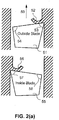
- FIG. 2(a) shows the above chip removal arrangement with a vertical sequence of a cross-sectional view of an outside blade 51 and an inside blade 55.
- the relative cutting velocity direction 59 applies to both blades 51 and 55.
- Outside blade 51 has a sharp cutting edge 53 which cuts and forms chip 52 on the outside gear flank (concave flank).
- the clearance edge 54 of blade 51 has a dull shape and is not engaged in any cutting of the inside flank (convex flank).
- Inside blade 55 has a sharp cutting edge 57 which cuts and forms chip 56 on the inside gear flank (convex flank).
- the clearance edge 58 of blade 55 has a dull shape and is not engaged in any cutting of the outside flank (concave flank).
- Figure 3(a) shows the front view onto a full profile blade 20.
- the front face 60 has a neutral orientation which provides the same side rake angles to both cutting edges 21 and 23. Also shown are the tip edge radii 22 and 24.
- the blade top width 25 is equal to the root width of the gear to be cut which allows blade 20 to remove chips from both gear flanks (concave and convex) simultaneously.
- the full profile cutting blade 20 in Figure 3(a) comprises of an outside cutting edge 21 with an edge radius 22, an inside cutting edge 23 with an inside edge radius 24 and a top width 25 which spaces the two cutting edges in order to cut the correct slot width.
- Figure 2(b) shows a vertical sequence of a cross-sectional view of a full profile blade 64 and a second full profile blade 69.
- the relative cutting velocity direction 59 applies to both blades 64 and 69.
- Blade 64 has a front face 60 which is perpendicular to the relative cutting direction 59.
- the two cutting edges 61 and 62 of blade 64 cut off a connected chip 63 from the convex and the concave gear flank, as well as from the root area (not shown).
- the cutting edges 61 and 62 of blade 64 act neutral (not sharp) because the front face 60 is perpendicular to the cutting velocity direction.
- the second blade 69 in Figure 2(b) has a geometry identical to blade 64, with a front face 65 which forms cutting edges 66 and 67 which do not appear to be sharp, but neutral, with respect to the relative cutting velocity 59.
- the chip 68 will be identical to chip 63.
- the radial adjustment of the full profile blades 64 and 69 in the cutter head such that cutting edge 61 has the same radial position in the cutter head than cutting edge 66 and cutting edge 62 has the same radial position in the cutter head than cutting edge 67 is practically impossible. It is not possible to realize different radial adjustments to the two cutting edges (e.g. 61 and 62) which are part of the same blade. Inaccuracies in the blade profile grinding as well as inaccuracies in the cutter head slots cannot be compensated by individual adjustments of the individual cutting edges.
- the chips 63 and 68 are large and bulky and difficult to remove from the cutting zone. Due to the chip forming on two opposite cutting edges with a neutral angle of front faces 60 and 65, the chip forming of the two cutting edges 61 and 62 as well as 65 and 57 opposes each other and hinders an optimal chip shearing and forming. As a result, the cutting forces and the temperatures of chips and parts generated by a cutting process using the tool geometry shown in Figure 2(b) are higher compared to the cutting forces and temperature of chips and parts generated by a cutting process using the tool geometry shown in Figure 2(a) .
- the blades 64 and 69 belong to different blade groups.
- Cutter heads with blades according to Figure 2b have one blade per blade group.
- the single blade type cutter heads are only applied to face milled bevel gears which are cut in a completing process, because completing bevel gears show a parallel slot width along the root bottom between toe and heel.
- the single blade cutting process (schematically shown in Figure 2(b) ), which only uses one blade type 64 in order to manufacture both flanks of each gear slot including the slot bottoms, has a number of disadvantages.
- the blade front face 60 which connects the both cutting edges (and in general is a plane surface) can only provide side rake angles of about zero degree for both cutting edges 61 and 62.
- DD 47583 disclosed a double-cutter head arrangement, where inside blades and outside blades are attributed to the single cutter heads of the double-cutter head arrangement such that the radial component of the working force is directed versus the seating surface of the cutting blade.
- US 2015/0306688 A1 discloses a bevel gear manufacturing face cutter head with the capability to adjust the cutting blades radially after they are pre-clamped and axially located.
- US 1,411,390 A provides a two-piece cutter head, one for each of two sets of cutter blades.
- US 7,775,749 B2 discloses a blade profile with a first cutting edge for a first flank, a second cutting edge for a second flank that faces the first flank, and a top cutting edge for the bottom of a tooth space.
- DE 852 029 C disclosed a cutter head with cutting blades displaceable along a direction being under an angle to the axis of rotation of the cutter head.
- the invention provides a gear cutting tool according to claim 1 and a method of cutting bevel and hypoid gears according to claim 3.
- the present invention comprises a gear cutting tool wherein each cutting blade group includes two differently positioned but identical cutting blades (e.g. one outside blade and one inside blade).
- the inventive blade arrangement only requires a single type of blade in order to simultaneously cut the convex and the concave tooth flanks of a gear as well as the root fillet and root bottom portions of tooth slots.
- the inventive cutter system allows radial adjustment of the outside cutting blade and the inside cutting blade independently of one another. Additionally, inside and outside cutting blades may be exchanged with one another.
- a cutting blade 30 is shown in Figure 3(b) and is provided with an inside cutting edge 31 which duplicates the pressure angle and shape of 23 and has a tip edge radius 32 which is identical to 24.
- the front face 36 of the cutting blade has a neutral orientation which provides the same rake angles to both cutting edges 31 and 33.
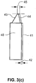
- the blade top width 35 is smaller than the top width 25 of the full profile blade 20 by an amount 42 ( Figure 3(c) ).
- Tip edge radius 34 is preferably identical to 22 and the outside cutting edge 33 has the same pressure angle and shape as 21.
- Cutting edge 33 is closer to cutting edge 31 (by the amount 42) compared to cutting edge 21 which has a larger distance to 23.
- Two cutting blades of the blade type 30 are positioned in a cutter head which has a small difference of the slot bottom radii. This is depicted in Figure 3(c) with cutting blades 40 and 41 which are both identical to cutting blade 30. Blades 40 and 41 are positioned behind each other but shifted sideways with respect to one another by the amount 42. This arrangement places cutting edge 31 of a first blade in position 43 and cutting edge 33 of a second blade in position 44.
- the arrangement of blades 40 and 41 provides an inside cutting edge 43 which is identical in its radial location, pressure angle and shape to cutting edge 23.
- the arrangement of blades 40 and 41 also provides a top width 45 over both blades which is equal to 25. Consequently, the cutting edge 44 has the same pressure angle, shape and radial location as cutting edge 21.
- the blade arrangement 40 and 41 consists of two differently positioned but identical blades (one outside blade and one inside blade). Hence, the cutting blades may be referred to as mono-blades.
- the produced gear slot geometry is identical to the geometry produced by full profile blade 20.
- the inventive blade arrangement only requires a single type of blade in order to simultaneously cut, in a completing cutter head, the convex and the concave flanks as well as the root fillets and root bottoms.
- Figure 2(c) shows the first mono-blade 41 acts as an outside blade with cutting edge 44 removing a chip 70 as a single side chip.
- the clearance side 72 of blade 41 shows a clearance gap 42 with respect to the convex flank.
- the next mono-blade 40 acts as an inside blade with cutting edge 43 removing a chip 71 as a single side chip.
- the clearance side 73 of blade 40 shows a clearance gap 42 with respect to the concave flank.
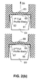
- Figure 4 shows a vertically represented sequence of cross-sectional views of a cutter head 82 with its center line 83 (axis of rotation) and an outside slot seating surface 84 with mono-blade 41 and an inside slot seating surface 85 with mono-blade 40.
- the blade point radius of the outside blade, which cuts the concave gear flank RW OB is achieved by placing blade 41 on seating surface 84 with slot bottom radius 80.
- the blade point radius of the inside blade, which cuts the convex gear flank RW IB is achieved by placing blade 40 on a seating surface 85 with slot bottom radius 81. Radius 81 is reduced versus radius 80 by the amount 42.
- the cutter head design in Figure 4 allows utilization of identical blades 40 and 41 with the result that blade 41 acts as outside blade while blade 40 acts as inside blade.
- the different slot bottom radii in conventional cutter heads with inside and outside blades are commonly stepped. Stepping means that the inside blades have a smaller slot bottom radius than the outside blades.
- the difference amount between the slot bottom radii of outside and inside blades are 5 to 20 times larger than the amount 42 required for the inventive mono-blade positioning.
- the difference in slot bottom radii allows conventional cutter heads to cover a wide spectrum of different bevel gear designs and also allows cutting of gears having a range of modules.
- Figure 5 shows a vertical sequence of cross-sectional views of a cutter head 82 with its center line 83 (axis of rotation).
- the blade seating surfaces 84 and 85 can be modified and plan-parallel spacer blocks 86 and 87 can be connected to them as shown in Figure 5 .
- Cutter head 82 can be utilized with or without the spacer blocks 86 and 87.
- Different sizes 90 of the spacer blocks can be prepared in order to achieve large radius span RW OB + ⁇ and RW IB + ⁇ by making a variety of spacer blocks 86 and 87 with different thicknesses available.
- the radius difference between outside blade 41 and inside blade 40 is realized in the seating surfaces 84 and 85 of the cutter head.
- the assortment of spacer blocks in the preferred embodiment uses blocks 86 and 87 of identical thickness 90 (for inside and outside blade slots).
- spacer blocks of different thickness for outside and inside blade slot. This is advantageous if a wide module range has to be covered.
- the different block thicknesses 86 and 87 also allow consolidation of a variety of different gear designs for the usage of the same blade geometry (in case of identical pressure angles but different gear slot widths).
- Another variation of the inventive cutter system is to make the slot bottom radii 80 and 81 identical and work the radius difference required into the spacer blocks 86 and 87. Also a combination where a partial amount of 42 is applied to the cutter design and a second partial amount of 42 is designed in the spacer blocks is possible.
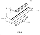
- the inventive mono-blade cutter head system can be realized in cutter heads with rectangular slots 15 and 16 like cutter head 10 in Figure 1 or in cutter heads with pentagon-shaped slot cross section (e.g. US 6,120,217 ) and stick blades according to 110 as shown in Figure 6 .
- the spacer block 111 will in this case have the form of a prism.
- Clamp block 114 is located below the blade 110 and a spacer block 111 above blade 110.
- the spacer block 111 fulfills the analogue function for blades with a pentagon shaped cross section 110 as the spacer blocks 86 and 87 fulfill for rectangular blades 41 and 40.
- the spacer block 111 will shift the usable blade width 113 about a distance of 112 to a larger radius.
- the thickness 112 of the spacer block 111 can be manufactured in order to exactly duplicate the thickness 90 of the rectangular spacer blocks 86 and 87.
- the inventive cutter head system can also be realized with radially adjustable cutters (e.g. US 2015/0290725 or US 2015/0306688 ).
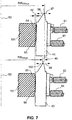
- Figure 7 shows a vertical sequence of cross-sectional views of a cutter head 101 with its center line 83 (axis of rotation) and an outside slot seating surface 84 with mono blade 41 and an inside slot seating surface 85 with mono blade 40.
- Figure 7 shows the seating surfaces 84 and 85 which are unmodified in the upper section and have a modification 95 and 96 in the lower section.
- respective adjustment screws 93 and 94 are implemented. A clockwise rotation of the adjustment screw 93 will move the tip of blade 41 in direction 97 and increase the point radius RW OBtrue .
- a counterclockwise rotation of adjustment screw 93 will move the blade tip in direction 98 and reduce the point radius RW OBtrue .
- a clockwise rotation of the adjustment screw 94 will move the tip of blade 40 in direction 99 and increase the point radius RW IBtrue .
- a counterclockwise rotation of adjustment screw 94 will move the blade tip in direction 100 and reduce the point radius RW IBtrue .
- cutter head seating surfaces 84 and 85 it is also possible to use unmodified seating surfaces and machine the modifications 95 and 96 on the spacer blocks 86 and 87 ( Figure 5 ). Also, a combination of cutter head seating surface modifications and spacer block modifications is practically possible and useful in particular cases.
- Another embodiment of the inventive tool arrangement is to use a cutter head 101 with outside blade slots 84 which have a slot bottom radius 80 equal to the radius 81 of the inside blade slots 85.
- the difference amount 42 is equal to zero.
- the outside blades 41 can be adjusted with larger base amounts in direction 97 and the inside blades 40 can be adjusted with small base amounts in direction 99 ( Figure 7 ).
- the mono-blades can be ground to a blade top width 35, which is 0.050mm less than the top width 25, required to cut the correct gear slot width and built in a cutter head 101 in the initial positions for inside and outside blades as shown in Figure 7 .
- outside blades 41 can be adjusted 0.025mm (plus or minus small truing amounts) in direction 97 and the inside blades 40 can be adjusted 0.025mm (plus or minus small truing amounts) in direction 100.
- This arrangement will also provide mono-blades 41 which only cut on the outside cutting edges and inside mono-blades 40 which only cut on the inside cutting edges.
- the mono-blade and cutter system as it was described above for the single indexing face milling process, can also be utilized in the continuous indexing face hobbing process.
- the blade timing cannot be controlled with individual front face distances between outside and inside blades.
- the blade timing which is the angular distance between the reference point of the inside blade cutting edge and the reference point of the outside blade cutting edge influences the slot with and therewith the tooth thickness. If the front face distance and all other parameter of the blade which is placed in an outside slot are equal to the parameters of the inside blade, then the correct tooth thickness in a completing cut can only be established with a change of the radial location of the cutting edges.
- a slot width discrepancy of for example + ⁇ s can be corrected by increasing the radius of the inside cutting edge by ⁇ s/2 and reduction of the outside cutting edge radius by ⁇ s/2.
- the correct tooth slot width (and tooth thickness) will be achieved by using identical blades in the cutter head slots for the outside cutting as well as in the cutter head slots for the inside cutting.
- the slot radii of outside and inside cutting slots have to be located in order to achieve for an average gear cutting the same radius of the reference point on both the outside and the inside cutting edge.
- spacer blocks 86 and 87 can be also utilized in face hobbing.
Landscapes
- Engineering & Computer Science (AREA)
- Mechanical Engineering (AREA)
- Milling Processes (AREA)
- Gear Processing (AREA)
Applications Claiming Priority (2)
| Application Number | Priority Date | Filing Date | Title |
|---|---|---|---|
| US201662289470P | 2016-02-01 | 2016-02-01 | |
| PCT/US2017/015791 WO2017136329A1 (en) | 2016-02-01 | 2017-01-31 | Mono-blade bevel gear cutting tool |
Publications (2)
| Publication Number | Publication Date |
|---|---|
| EP3411175A1 EP3411175A1 (en) | 2018-12-12 |
| EP3411175B1 true EP3411175B1 (en) | 2021-08-18 |
Family
ID=58018275
Family Applications (1)
| Application Number | Title | Priority Date | Filing Date |
|---|---|---|---|
| EP17704920.2A Active EP3411175B1 (en) | 2016-02-01 | 2017-01-31 | Bevel and hypoid gear cutting tool and method of cutting bevel and hypoid gears |
Country Status (7)
| Country | Link |
|---|---|
| US (1) | US10814415B2 (enExample) |
| EP (1) | EP3411175B1 (enExample) |
| JP (1) | JP7053472B2 (enExample) |
| KR (1) | KR102386725B1 (enExample) |
| CN (1) | CN108602145B (enExample) |
| BR (1) | BR112018014035A2 (enExample) |
| WO (1) | WO2017136329A1 (enExample) |
Families Citing this family (7)
| Publication number | Priority date | Publication date | Assignee | Title |
|---|---|---|---|---|
| WO2018093755A1 (en) | 2016-11-15 | 2018-05-24 | The Gleason Works | Cutter with positive seated round blades sticks for bevel gear cutting |
| WO2019014509A1 (en) * | 2017-07-13 | 2019-01-17 | The Gleason Works | MACHINE FOR TILLING CONICAL GEAR DENTURES AND BLADE CONSOLIDATION |
| EP3791985A1 (de) * | 2019-09-10 | 2021-03-17 | Flender GmbH | Wälzschälwerkzeug und verfahren zur spanenden erzeugung einer verzahnung eines zahnrads durch wälzschälen |
| DE102020003346B3 (de) | 2020-06-03 | 2021-09-02 | Rainer Richardt | Umfangsstabmesserkopf |
| JP7619285B2 (ja) * | 2022-01-11 | 2025-01-22 | トヨタ自動車株式会社 | 切断加工方法 |
| DE102022103513A1 (de) * | 2022-02-15 | 2023-08-17 | Man Truck & Bus Se | Verfahren zum Verzahnen von verschieden großen Kegelrädern |
| EP4561778A1 (en) * | 2022-07-29 | 2025-06-04 | The Gleason Works | Bevel gear cutting tool having four-sided, non-rectangular cutter head slots and cutting blades |
Family Cites Families (26)
| Publication number | Priority date | Publication date | Assignee | Title |
|---|---|---|---|---|
| DD47583A (enExample) * | ||||
| DE47583C (de) | A. H. FRANCKE, Hof - Pianoforte - Fabrik in Leipzig, Gustav-Adolphstr. 47 | Einrichtung zum Abheben des Dämpfers bei Flügeln, welche mit der sogenannten jANKö'schen Klaviatur versehen sind | ||
| US781851A (en) * | 1901-02-23 | 1905-02-07 | Sidney Newbold | Tool holding and adjusting mechanism. |
| US1411390A (en) * | 1917-11-05 | 1922-04-04 | Security Trust Company | Gear cutter |
| FR956519A (enExample) | 1946-11-02 | 1950-02-02 | ||
| US2586955A (en) * | 1950-04-12 | 1952-02-26 | Ingersoll Milling Machine Co | Finishing cutter |
| US3571876A (en) * | 1968-10-21 | 1971-03-23 | Gleason Works | Means for mounting blades in a cutter |
| US3961406A (en) | 1973-03-30 | 1976-06-08 | C. L. Frost & Son, Inc. | Method of pulley construction |
| US3961403A (en) * | 1973-12-27 | 1976-06-08 | The Gleason Works | Cutter head assembly for gear cutting machinery |
| US4268194A (en) * | 1979-05-21 | 1981-05-19 | Illinois Tool Works Inc. | Independent axial and radial adjustment for a gear cutter |
| JPS58117314U (ja) * | 1982-02-02 | 1983-08-10 | トヨタ自動車株式会社 | かさ歯車用歯切カツタのブレ−ド形状 |
| US5598618A (en) * | 1989-09-29 | 1997-02-04 | Aquino; Giovanni | Mainrotor machining process and apparatus |
| DE19624685C1 (de) * | 1996-06-20 | 1997-02-20 | Oerlikon Geartec Ag | Rundstabmesser und insbesondere dafür vorgesehener Messerkopf |
| BR9907809A (pt) | 1998-02-11 | 2000-10-17 | Gleason Works | Ferramenta de corte para a produção de peças de trabalho denteadas, membro de corpo de cortador de uma ferramenta de corte para a produção de artigos denteados, membro de anel de cortador posicionável em torno de um membro de corpo de cortador, meios de fixação para segurar uma ou mais lâminas de corte em um cabeçote de cortador, e, lâmina de corte inserìvel em um membro de corpo de cortador |
| MXPA01011169A (es) * | 1999-05-05 | 2002-05-06 | Gleason Works | Metodo para producir una herramienta de corte para engranajes que se tallan por fresa matriz. |
| JP2001347412A (ja) * | 2000-04-06 | 2001-12-18 | Yutaka Seimitsu Kogyo Ltd | 正面カッタおよびカッタ用ブレード |
| US6632050B2 (en) * | 2001-09-06 | 2003-10-14 | Kennametal Inc. | Face hobbing cutter |
| US7059810B2 (en) * | 2002-04-18 | 2006-06-13 | Kennametal Inc. | Gear hobbing cutter system |
| US7775749B2 (en) * | 2003-05-22 | 2010-08-17 | Klingelnberg Gmbh | Method, bar blade, and use thereof for milling spiral bevel gears and hypoid gears |
| CN2717595Y (zh) * | 2004-08-02 | 2005-08-17 | 哈尔滨第一工具有限公司 | 克林贝尔制摆线等高齿锥齿轮铣刀 |
| JP5541930B2 (ja) | 2009-01-08 | 2014-07-09 | 富士重工業株式会社 | 工具ヘッド |
| EP2412467B1 (de) * | 2010-07-29 | 2014-01-08 | Klingelnberg AG | Verfahren zum Fräsen einer Kegelradverzahnung im kontinuierlichen Fräsverfahren |
| EP2535134B1 (de) | 2011-06-16 | 2018-01-24 | Klingelnberg AG | Verfahren zum Vorverzahnen mehrerer unterschiedlicher Kegelräder |
| EP2647460B1 (de) | 2012-04-02 | 2014-12-10 | Klingelnberg AG | Verfahren zum Herstellen von Kegel- oder Hyproidrädern im Tauchverfahren |
| CN104768688B (zh) | 2012-11-09 | 2017-04-26 | 格里森工场 | 具有条形刀片的径向可调整性的齿轮刀具 |
| RU2660427C2 (ru) * | 2012-12-14 | 2018-07-06 | Те Глисон Воркс | Зуборезная фреза с радиально регулируемыми стержневыми резцами квадратного или прямоугольного поперечного сечения |
-
2017
- 2017-01-31 US US16/069,899 patent/US10814415B2/en active Active
- 2017-01-31 JP JP2018538887A patent/JP7053472B2/ja active Active
- 2017-01-31 BR BR112018014035-0A patent/BR112018014035A2/pt not_active Application Discontinuation
- 2017-01-31 KR KR1020187022431A patent/KR102386725B1/ko active Active
- 2017-01-31 CN CN201780008719.1A patent/CN108602145B/zh active Active
- 2017-01-31 EP EP17704920.2A patent/EP3411175B1/en active Active
- 2017-01-31 WO PCT/US2017/015791 patent/WO2017136329A1/en not_active Ceased
Also Published As
| Publication number | Publication date |
|---|---|
| JP7053472B2 (ja) | 2022-04-12 |
| KR102386725B1 (ko) | 2022-04-14 |
| US20190022779A1 (en) | 2019-01-24 |
| JP2019503877A (ja) | 2019-02-14 |
| KR20180109912A (ko) | 2018-10-08 |
| WO2017136329A1 (en) | 2017-08-10 |
| EP3411175A1 (en) | 2018-12-12 |
| CN108602145B (zh) | 2021-04-09 |
| CN108602145A (zh) | 2018-09-28 |
| BR112018014035A2 (pt) | 2018-12-11 |
| US10814415B2 (en) | 2020-10-27 |
Similar Documents
| Publication | Publication Date | Title |
|---|---|---|
| EP3411175B1 (en) | Bevel and hypoid gear cutting tool and method of cutting bevel and hypoid gears | |
| CN1116142C (zh) | 带有切削刀片的高精度铣刀 | |
| EP2628559B1 (en) | Face hobbing cutter system and use of the same | |
| JP6022798B2 (ja) | ミーリング工具及びミーリング・インサート・キット | |
| EP3500383B1 (en) | Power skiving pressure angle correction without tool geometry change | |
| US8882414B2 (en) | Method and system for milling a bevel gear tooth system in a continuous miling process | |
| CN102266975B (zh) | 枞树形刀具以及使用该刀具的叶轮叶根部的加工方法 | |
| EP3200948B1 (en) | Axial hob with multi-revolution cutting teeth and method of manufacturing a gear with an axial hob | |
| US20120321404A1 (en) | Method for Gear Pre-Cutting of a Plurality of Different Bevel Gears and Use of an According Milling Tool | |
| CN110678285B (zh) | 产生经切齿的工件的方法,以及适用于此的控制程序、刀具和切齿机 | |
| EP2682215A2 (en) | A milling insert | |
| CN101622097A (zh) | 制造铣刀的方法 | |
| JP2019503877A5 (enExample) | ||
| CA2108122C (en) | Rotary disc cutter and method of making same | |
| US6336777B1 (en) | Face hobbing of hypoid gears using a two-spindle machine | |
| US6536999B1 (en) | Gear cutter blade | |
| EP1896212B1 (en) | Cutter for forming a slot | |
| EP3898050B1 (en) | Independent pressure angle corrections for power skiving | |
| Stadtfeld | Pentac Mono-RT, High Performance Face Milling Cutter Heads | |
| JP2005238408A (ja) | 歯切りカッター、歯切り盤、及びギヤ形成方法 | |
| JPH106135A (ja) | 歯の加工方法 |
Legal Events
| Date | Code | Title | Description |
|---|---|---|---|
| STAA | Information on the status of an ep patent application or granted ep patent |
Free format text: STATUS: UNKNOWN |
|
| STAA | Information on the status of an ep patent application or granted ep patent |
Free format text: STATUS: THE INTERNATIONAL PUBLICATION HAS BEEN MADE |
|
| PUAI | Public reference made under article 153(3) epc to a published international application that has entered the european phase |
Free format text: ORIGINAL CODE: 0009012 |
|
| STAA | Information on the status of an ep patent application or granted ep patent |
Free format text: STATUS: REQUEST FOR EXAMINATION WAS MADE |
|
| 17P | Request for examination filed |
Effective date: 20180628 |
|
| AK | Designated contracting states |
Kind code of ref document: A1 Designated state(s): AL AT BE BG CH CY CZ DE DK EE ES FI FR GB GR HR HU IE IS IT LI LT LU LV MC MK MT NL NO PL PT RO RS SE SI SK SM TR |
|
| AX | Request for extension of the european patent |
Extension state: BA ME |
|
| DAV | Request for validation of the european patent (deleted) | ||
| DAX | Request for extension of the european patent (deleted) | ||
| GRAP | Despatch of communication of intention to grant a patent |
Free format text: ORIGINAL CODE: EPIDOSNIGR1 |
|
| STAA | Information on the status of an ep patent application or granted ep patent |
Free format text: STATUS: GRANT OF PATENT IS INTENDED |
|
| INTG | Intention to grant announced |
Effective date: 20210609 |
|
| GRAS | Grant fee paid |
Free format text: ORIGINAL CODE: EPIDOSNIGR3 |
|
| GRAA | (expected) grant |
Free format text: ORIGINAL CODE: 0009210 |
|
| STAA | Information on the status of an ep patent application or granted ep patent |
Free format text: STATUS: THE PATENT HAS BEEN GRANTED |
|
| AK | Designated contracting states |
Kind code of ref document: B1 Designated state(s): AL AT BE BG CH CY CZ DE DK EE ES FI FR GB GR HR HU IE IS IT LI LT LU LV MC MK MT NL NO PL PT RO RS SE SI SK SM TR |
|
| REG | Reference to a national code |
Ref country code: GB Ref legal event code: FG4D |
|
| REG | Reference to a national code |
Ref country code: CH Ref legal event code: EP |
|
| REG | Reference to a national code |
Ref country code: DE Ref legal event code: R096 Ref document number: 602017044221 Country of ref document: DE |
|
| REG | Reference to a national code |
Ref country code: IE Ref legal event code: FG4D Ref country code: AT Ref legal event code: REF Ref document number: 1421172 Country of ref document: AT Kind code of ref document: T Effective date: 20210915 |
|
| REG | Reference to a national code |
Ref country code: LT Ref legal event code: MG9D |
|
| REG | Reference to a national code |
Ref country code: NL Ref legal event code: MP Effective date: 20210818 |
|
| REG | Reference to a national code |
Ref country code: AT Ref legal event code: MK05 Ref document number: 1421172 Country of ref document: AT Kind code of ref document: T Effective date: 20210818 |
|
| PG25 | Lapsed in a contracting state [announced via postgrant information from national office to epo] |
Ref country code: PT Free format text: LAPSE BECAUSE OF FAILURE TO SUBMIT A TRANSLATION OF THE DESCRIPTION OR TO PAY THE FEE WITHIN THE PRESCRIBED TIME-LIMIT Effective date: 20211220 Ref country code: NO Free format text: LAPSE BECAUSE OF FAILURE TO SUBMIT A TRANSLATION OF THE DESCRIPTION OR TO PAY THE FEE WITHIN THE PRESCRIBED TIME-LIMIT Effective date: 20211118 Ref country code: ES Free format text: LAPSE BECAUSE OF FAILURE TO SUBMIT A TRANSLATION OF THE DESCRIPTION OR TO PAY THE FEE WITHIN THE PRESCRIBED TIME-LIMIT Effective date: 20210818 Ref country code: FI Free format text: LAPSE BECAUSE OF FAILURE TO SUBMIT A TRANSLATION OF THE DESCRIPTION OR TO PAY THE FEE WITHIN THE PRESCRIBED TIME-LIMIT Effective date: 20210818 Ref country code: AT Free format text: LAPSE BECAUSE OF FAILURE TO SUBMIT A TRANSLATION OF THE DESCRIPTION OR TO PAY THE FEE WITHIN THE PRESCRIBED TIME-LIMIT Effective date: 20210818 Ref country code: BG Free format text: LAPSE BECAUSE OF FAILURE TO SUBMIT A TRANSLATION OF THE DESCRIPTION OR TO PAY THE FEE WITHIN THE PRESCRIBED TIME-LIMIT Effective date: 20211118 Ref country code: LT Free format text: LAPSE BECAUSE OF FAILURE TO SUBMIT A TRANSLATION OF THE DESCRIPTION OR TO PAY THE FEE WITHIN THE PRESCRIBED TIME-LIMIT Effective date: 20210818 Ref country code: SE Free format text: LAPSE BECAUSE OF FAILURE TO SUBMIT A TRANSLATION OF THE DESCRIPTION OR TO PAY THE FEE WITHIN THE PRESCRIBED TIME-LIMIT Effective date: 20210818 Ref country code: RS Free format text: LAPSE BECAUSE OF FAILURE TO SUBMIT A TRANSLATION OF THE DESCRIPTION OR TO PAY THE FEE WITHIN THE PRESCRIBED TIME-LIMIT Effective date: 20210818 Ref country code: HR Free format text: LAPSE BECAUSE OF FAILURE TO SUBMIT A TRANSLATION OF THE DESCRIPTION OR TO PAY THE FEE WITHIN THE PRESCRIBED TIME-LIMIT Effective date: 20210818 |
|
| PG25 | Lapsed in a contracting state [announced via postgrant information from national office to epo] |
Ref country code: PL Free format text: LAPSE BECAUSE OF FAILURE TO SUBMIT A TRANSLATION OF THE DESCRIPTION OR TO PAY THE FEE WITHIN THE PRESCRIBED TIME-LIMIT Effective date: 20210818 Ref country code: LV Free format text: LAPSE BECAUSE OF FAILURE TO SUBMIT A TRANSLATION OF THE DESCRIPTION OR TO PAY THE FEE WITHIN THE PRESCRIBED TIME-LIMIT Effective date: 20210818 Ref country code: GR Free format text: LAPSE BECAUSE OF FAILURE TO SUBMIT A TRANSLATION OF THE DESCRIPTION OR TO PAY THE FEE WITHIN THE PRESCRIBED TIME-LIMIT Effective date: 20211119 |
|
| PG25 | Lapsed in a contracting state [announced via postgrant information from national office to epo] |
Ref country code: NL Free format text: LAPSE BECAUSE OF FAILURE TO SUBMIT A TRANSLATION OF THE DESCRIPTION OR TO PAY THE FEE WITHIN THE PRESCRIBED TIME-LIMIT Effective date: 20210818 |
|
| PG25 | Lapsed in a contracting state [announced via postgrant information from national office to epo] |
Ref country code: DK Free format text: LAPSE BECAUSE OF FAILURE TO SUBMIT A TRANSLATION OF THE DESCRIPTION OR TO PAY THE FEE WITHIN THE PRESCRIBED TIME-LIMIT Effective date: 20210818 |
|
| REG | Reference to a national code |
Ref country code: DE Ref legal event code: R097 Ref document number: 602017044221 Country of ref document: DE |
|
| PG25 | Lapsed in a contracting state [announced via postgrant information from national office to epo] |
Ref country code: SM Free format text: LAPSE BECAUSE OF FAILURE TO SUBMIT A TRANSLATION OF THE DESCRIPTION OR TO PAY THE FEE WITHIN THE PRESCRIBED TIME-LIMIT Effective date: 20210818 Ref country code: SK Free format text: LAPSE BECAUSE OF FAILURE TO SUBMIT A TRANSLATION OF THE DESCRIPTION OR TO PAY THE FEE WITHIN THE PRESCRIBED TIME-LIMIT Effective date: 20210818 Ref country code: RO Free format text: LAPSE BECAUSE OF FAILURE TO SUBMIT A TRANSLATION OF THE DESCRIPTION OR TO PAY THE FEE WITHIN THE PRESCRIBED TIME-LIMIT Effective date: 20210818 Ref country code: EE Free format text: LAPSE BECAUSE OF FAILURE TO SUBMIT A TRANSLATION OF THE DESCRIPTION OR TO PAY THE FEE WITHIN THE PRESCRIBED TIME-LIMIT Effective date: 20210818 Ref country code: CZ Free format text: LAPSE BECAUSE OF FAILURE TO SUBMIT A TRANSLATION OF THE DESCRIPTION OR TO PAY THE FEE WITHIN THE PRESCRIBED TIME-LIMIT Effective date: 20210818 Ref country code: AL Free format text: LAPSE BECAUSE OF FAILURE TO SUBMIT A TRANSLATION OF THE DESCRIPTION OR TO PAY THE FEE WITHIN THE PRESCRIBED TIME-LIMIT Effective date: 20210818 |
|
| PLBE | No opposition filed within time limit |
Free format text: ORIGINAL CODE: 0009261 |
|
| STAA | Information on the status of an ep patent application or granted ep patent |
Free format text: STATUS: NO OPPOSITION FILED WITHIN TIME LIMIT |
|
| 26N | No opposition filed |
Effective date: 20220519 |
|
| PG25 | Lapsed in a contracting state [announced via postgrant information from national office to epo] |
Ref country code: IT Free format text: LAPSE BECAUSE OF FAILURE TO SUBMIT A TRANSLATION OF THE DESCRIPTION OR TO PAY THE FEE WITHIN THE PRESCRIBED TIME-LIMIT Effective date: 20210818 |
|
| PG25 | Lapsed in a contracting state [announced via postgrant information from national office to epo] |
Ref country code: SI Free format text: LAPSE BECAUSE OF FAILURE TO SUBMIT A TRANSLATION OF THE DESCRIPTION OR TO PAY THE FEE WITHIN THE PRESCRIBED TIME-LIMIT Effective date: 20210818 Ref country code: MC Free format text: LAPSE BECAUSE OF FAILURE TO SUBMIT A TRANSLATION OF THE DESCRIPTION OR TO PAY THE FEE WITHIN THE PRESCRIBED TIME-LIMIT Effective date: 20210818 |
|
| GBPC | Gb: european patent ceased through non-payment of renewal fee |
Effective date: 20220131 |
|
| REG | Reference to a national code |
Ref country code: BE Ref legal event code: MM Effective date: 20220131 |
|
| PG25 | Lapsed in a contracting state [announced via postgrant information from national office to epo] |
Ref country code: LU Free format text: LAPSE BECAUSE OF NON-PAYMENT OF DUE FEES Effective date: 20220131 Ref country code: GB Free format text: LAPSE BECAUSE OF NON-PAYMENT OF DUE FEES Effective date: 20220131 |
|
| PG25 | Lapsed in a contracting state [announced via postgrant information from national office to epo] |
Ref country code: FR Free format text: LAPSE BECAUSE OF NON-PAYMENT OF DUE FEES Effective date: 20220131 Ref country code: BE Free format text: LAPSE BECAUSE OF NON-PAYMENT OF DUE FEES Effective date: 20220131 |
|
| PG25 | Lapsed in a contracting state [announced via postgrant information from national office to epo] |
Ref country code: IE Free format text: LAPSE BECAUSE OF NON-PAYMENT OF DUE FEES Effective date: 20220131 |
|
| PG25 | Lapsed in a contracting state [announced via postgrant information from national office to epo] |
Ref country code: HU Free format text: LAPSE BECAUSE OF FAILURE TO SUBMIT A TRANSLATION OF THE DESCRIPTION OR TO PAY THE FEE WITHIN THE PRESCRIBED TIME-LIMIT; INVALID AB INITIO Effective date: 20170131 |
|
| PG25 | Lapsed in a contracting state [announced via postgrant information from national office to epo] |
Ref country code: MK Free format text: LAPSE BECAUSE OF FAILURE TO SUBMIT A TRANSLATION OF THE DESCRIPTION OR TO PAY THE FEE WITHIN THE PRESCRIBED TIME-LIMIT Effective date: 20210818 Ref country code: CY Free format text: LAPSE BECAUSE OF FAILURE TO SUBMIT A TRANSLATION OF THE DESCRIPTION OR TO PAY THE FEE WITHIN THE PRESCRIBED TIME-LIMIT Effective date: 20210818 |
|
| PG25 | Lapsed in a contracting state [announced via postgrant information from national office to epo] |
Ref country code: TR Free format text: LAPSE BECAUSE OF FAILURE TO SUBMIT A TRANSLATION OF THE DESCRIPTION OR TO PAY THE FEE WITHIN THE PRESCRIBED TIME-LIMIT Effective date: 20210818 |
|
| PG25 | Lapsed in a contracting state [announced via postgrant information from national office to epo] |
Ref country code: MT Free format text: LAPSE BECAUSE OF FAILURE TO SUBMIT A TRANSLATION OF THE DESCRIPTION OR TO PAY THE FEE WITHIN THE PRESCRIBED TIME-LIMIT Effective date: 20210818 |
|
| PGFP | Annual fee paid to national office [announced via postgrant information from national office to epo] |
Ref country code: DE Payment date: 20250129 Year of fee payment: 9 |
|
| PGFP | Annual fee paid to national office [announced via postgrant information from national office to epo] |
Ref country code: CH Payment date: 20250201 Year of fee payment: 9 |