EP3410571A1 - Découpe de tôles pour un rotor d'une machine électrique, rotor pour une machine électrique et machine électrique pourvue de rotor - Google Patents
Découpe de tôles pour un rotor d'une machine électrique, rotor pour une machine électrique et machine électrique pourvue de rotor Download PDFInfo
- Publication number
- EP3410571A1 EP3410571A1 EP18158946.6A EP18158946A EP3410571A1 EP 3410571 A1 EP3410571 A1 EP 3410571A1 EP 18158946 A EP18158946 A EP 18158946A EP 3410571 A1 EP3410571 A1 EP 3410571A1
- Authority
- EP
- European Patent Office
- Prior art keywords
- magnet
- sheet metal
- metal section
- web
- webs
- Prior art date
- Legal status (The legal status is an assumption and is not a legal conclusion. Google has not performed a legal analysis and makes no representation as to the accuracy of the status listed.)
- Granted
Links
- 239000002184 metal Substances 0.000 title claims abstract description 91
- 229910052751 metal Inorganic materials 0.000 title claims abstract description 91
- 238000003475 lamination Methods 0.000 abstract description 13
- 239000000463 material Substances 0.000 abstract description 12
- 230000008901 benefit Effects 0.000 description 4
- 230000008878 coupling Effects 0.000 description 4
- 238000010168 coupling process Methods 0.000 description 4
- 238000005859 coupling reaction Methods 0.000 description 4
- 229910001369 Brass Inorganic materials 0.000 description 3
- 239000010951 brass Substances 0.000 description 3
- 238000005457 optimization Methods 0.000 description 3
- XEEYBQQBJWHFJM-UHFFFAOYSA-N Iron Chemical compound [Fe] XEEYBQQBJWHFJM-UHFFFAOYSA-N 0.000 description 2
- 230000005540 biological transmission Effects 0.000 description 2
- 150000001875 compounds Chemical class 0.000 description 2
- 230000009467 reduction Effects 0.000 description 2
- 229910000831 Steel Inorganic materials 0.000 description 1
- 238000010276 construction Methods 0.000 description 1
- 230000004907 flux Effects 0.000 description 1
- 229910052742 iron Inorganic materials 0.000 description 1
- 230000001788 irregular Effects 0.000 description 1
- 230000002093 peripheral effect Effects 0.000 description 1
- 230000035699 permeability Effects 0.000 description 1
- 239000010959 steel Substances 0.000 description 1
- 239000013585 weight reducing agent Substances 0.000 description 1
Images


Classifications
-
- H—ELECTRICITY
- H02—GENERATION; CONVERSION OR DISTRIBUTION OF ELECTRIC POWER
- H02K—DYNAMO-ELECTRIC MACHINES
- H02K1/00—Details of the magnetic circuit
- H02K1/06—Details of the magnetic circuit characterised by the shape, form or construction
- H02K1/22—Rotating parts of the magnetic circuit
- H02K1/27—Rotor cores with permanent magnets
- H02K1/2706—Inner rotors
- H02K1/272—Inner rotors the magnetisation axis of the magnets being perpendicular to the rotor axis
- H02K1/274—Inner rotors the magnetisation axis of the magnets being perpendicular to the rotor axis the rotor consisting of two or more circumferentially positioned magnets
- H02K1/2753—Inner rotors the magnetisation axis of the magnets being perpendicular to the rotor axis the rotor consisting of two or more circumferentially positioned magnets the rotor consisting of magnets or groups of magnets arranged with alternating polarity
- H02K1/276—Magnets embedded in the magnetic core, e.g. interior permanent magnets [IPM]
- H02K1/2766—Magnets embedded in the magnetic core, e.g. interior permanent magnets [IPM] having a flux concentration effect
-
- H—ELECTRICITY
- H02—GENERATION; CONVERSION OR DISTRIBUTION OF ELECTRIC POWER
- H02K—DYNAMO-ELECTRIC MACHINES
- H02K1/00—Details of the magnetic circuit
- H02K1/06—Details of the magnetic circuit characterised by the shape, form or construction
- H02K1/22—Rotating parts of the magnetic circuit
- H02K1/28—Means for mounting or fastening rotating magnetic parts on to, or to, the rotor structures
- H02K1/30—Means for mounting or fastening rotating magnetic parts on to, or to, the rotor structures using intermediate parts, e.g. spiders
-
- H—ELECTRICITY
- H02—GENERATION; CONVERSION OR DISTRIBUTION OF ELECTRIC POWER
- H02K—DYNAMO-ELECTRIC MACHINES
- H02K2213/00—Specific aspects, not otherwise provided for and not covered by codes H02K2201/00 - H02K2211/00
- H02K2213/03—Machines characterised by numerical values, ranges, mathematical expressions or similar information
Definitions
- the present invention relates to a laminated section for a rotor of an electrical machine, wherein the sheet metal section has a central connection means for connection to a shaft, wherein the sheet metal section with respect to a radial direction extending in a circumferential direction outside area and between the outside area and the connecting means arranged in the circumferential direction extending inner region, wherein the outer region n, n ⁇ 2, distributed along the circumferential direction arranged magnetic poles, wherein the magnetic poles are arranged corresponding to the corners of a, in particular regular, first n-corner. Furthermore, the present invention relates to a rotor for an electric machine with a sheet metal section and an electric machine with a rotor.
- An electric machine comprises a stator with an electrical coil for generating a magnetic stator field and a rotor rotatably mounted in the interior of the stator on a rotor shaft.
- the rotor is constructed from a laminated core, wherein the laminated core comprises one or more laminations.
- the laminations or the laminated core have a central connecting means, in particular a central receiving opening, for receiving a connection to a rotor shaft.
- the laminations or the laminated core are approximately circular in a plan view along the rotor shaft and have in the circumferential direction in an outer region in the vicinity of an outer periphery of the sheet metal section or the laminated core to magnetic poles.
- Each magnetic pole can have one or more magnets, in particular permanent magnets.
- the DE 10 2013 201 199 A1 discloses an electric machine having a rotor having at least one electrical sheet, wherein the electrical sheet has webs, wherein the webs have a deformation normal to the plane of the electrical sheet.
- an electric machine with permanent magnets wherein non-magnetic portions are formed in a rotor core, wherein the non-magnetic portions are disposed at opposite ends of a permanent magnet.
- the present invention has for its object to provide a sheet metal section for a rotor of an electric machine, which is electromagnetically and mechanically optimized and has maximum performance with minimal material use and weight and speed stability required. It is another object of the present application to provide a sheet metal section for a rotor of an electric machine, which has an improved connection of the sheet metal section with a shaft, in particular a rotor shaft. Another object of the present invention is to provide a rotor for an electric machine or in the provision of an electric machine with a rotor, with which the aforementioned objects are achieved.
- a sheet metal section for a rotor of an electric machine wherein the sheet metal section a central Connecting means for connection with a shaft, wherein the sheet metal section with respect to a radial direction has a circumferentially extending outer region and arranged between the outer region and the connecting means in the circumferential inner region, said outer region n, n ⁇ 2, distributed along the circumferential direction Magnetic poles, wherein the magnetic poles are arranged corresponding to the corners of a, in particular regular, first n-corner, wherein also the inner region has webs, each web connects two magnetic poles and / or extends between each two magnetic poles, wherein the webs substantially form an n-star, in particular a hexagram or an octagram or a decagram, wherein the n-star has a second inner n-corner, wherein the connecting means is arranged in the second n-corner and with the second n-edge bordering web
- the sheet metal section is preferably formed in a plan view in an approximately circular, wherein the connecting means for a connection with a shaft centrally, that is arranged around the center of the circular sheet metal section. Seen in a radial direction from the inside to the outside is located outside of the connecting means in a peripheral circumferential inner region. The interior is followed by a surrounding outdoor area.
- the outdoor area has magnetic poles and is therefore also called a magnetic circuit.
- the inner area serves to connect the outer area to the connecting means and preferably has no magnetic poles.
- the inner area can also be called Kraft Vietnamese.
- the magnetic poles arranged in the outer region are arranged in the outer region over the circumference or in the circumferential direction of the sheet metal section.
- the magnetic poles form a first n-shaped corner, the magnetic poles being arranged corresponding to the corners of the first n-corner.
- the magnetic poles define or form a hexagon.
- an arbitrary, but the same point in all magnetic poles are chosen, so that these points are arranged corresponding to the corners of a first n-corner.
- the first n-corner as in the above example, the hexagon, can be regularly formed or irregular.
- the inner area has webs, wherein each web connects two magnetic poles each and / or extends between each two magnetic poles.
- the webs essentially form an n-star, in particular a hexagram or an octagram or a decagram.
- an n-star is a star inscribed in the imaginary first n-corner, the tips of the star being arranged at the corners of the first n-corner, that is to say adjacent to the magnetic poles, or with the corners of the first n-corner. Ecks or are connected to the magnetic poles.
- the n-star may have the form of a flipped star polygon, wherein the edges of the flipped star polygon are formed by the webs of the inner region. For example, if four magnetic poles are provided, they essentially form a regular quadrilateral. The webs then connect the four corners of the square in the form of a four-star, which represents a special embodiment of a tumbled star polygon. In the case of six magnetic poles, the six magnetic poles define the corners of a regular hexagon. The webs are then preferably aligned and arranged in the form of a hexagram.
- the webs do not have to be formed exactly straight, but may also have bends, bends or kinks. It is essential that the webs each connect two magnetic poles by their configuration as n-star. In this case, each web preferably connects a first magnetic pole to a second magnetic pole which, with respect to the connection means, is arranged approximately opposite the first magnetic pole on the other side of the sheet metal section.
- the webs are thus preferably designed such that approximately opposite magnetic poles are mechanically interconnected and occurring during operation centrifugal forces between the respective opposite and connected by the webs magnetic poles are transmitted via the webs.
- each magnetic pole is connected to at least one approximately opposite magnetic pole in such a way that they are “suspended” together and the forces acting on them centrifugal forces are transmitted to each other. Since the centrifugal forces are transmitted between approximately opposite magnetic poles, the centrifugal forces attack little or not at the connecting means, so that the connection of the sheet metal section with a shaft, in particular with a rotor shaft is improved. In particular, in the case of a shrink fit as a connection to the shrink fit radially acting forces, in particular centrifugal forces that would weaken the shrink fit, can be reduced or avoided.
- An n-star in particular an n-star designed as a swept-over star polygon, circumscribes in its interior or has a second n-corner in its interior, which is defined or formed by web portions of the webs.
- the second N-corner need not necessarily be bounded by straight web sections or formed by straight web sections. If the webs, for example, arcuate or executed with kinks or bends, the second inscribed n-corner is also bordered or formed by arcuate or provided with bends or bends web portions.
- the connecting means is arranged in the second n-corner and connected to the second n-edge bordering and forming web portions of the webs or the second connecting means is at least partially formed by the second n-edge bordering web portions. In other words, the connecting means may be at least partially part of the inner region or the webs of the inner region.
- the connecting means is arranged in the second n-edge or is at least partially formed by the second n-edge bordering web portions and since the force, in particular the centrifugal force, is transmitted between two substantially opposite magnetic poles along the webs and web portions, the grip Centrifugal forces substantially tangentially and not radially to the connecting means, wherein cancel the forces, in particular the centrifugal forces, opposite magnetic poles in about.
- the inventive measures thus an electromagnetic and mechanical optimization of a sheet metal section is obtained, wherein the compound of the sheet metal section is improved with a shaft, in particular with respect to electromagnetic forces and centrifugal forces, so that prevents a compound, in particular a shrink fit, between connecting means and shaft of the electric Machine is weakened.
- the connecting means is a retaining ring, and / or that the connection is a shrink connection, and / or that the shaft is a rotor shaft, and / or that the connecting means are central is arranged in the sheet metal section, and / or that the connecting means has a, in particular circular, receiving opening for the shaft.
- the connecting means preferably has a, in particular circular receiving opening, for the shaft.
- the connecting means may preferably be formed as a retaining ring.
- a shrink connection or a shrink fit can be provided for connecting the connecting means formed as a retaining ring with a shaft, in particular a rotor shaft.
- a circular receiving opening is particularly suitable.
- a designed as a particular circular retaining ring connecting means provides an optimal connection between the sheet metal section and the rotor shaft.
- each web for n ⁇ 4 connects two magnetic poles not adjacent in the circumferential direction.
- the webs or the web sections or the star polygon do not form the sides of the imaginary first n-corner, which is defined by the magnetic poles.
- the magnetic poles form a imaginary quadrilateral, one magnet pole each being arranged approximately on one corner of the imaginary quadrilateral.
- the webs then each run from a first magnetic pole to a diametrically opposite magnetic pole and must have a slight curvature or kinks or the like to run past the connecting means.
- two webs extending between a first magnetic pole and an opposing second magnetic pole then form approximately the shape of a lens or an ellipse with pointed corners.
- These approximately lenticular or elliptical-shaped web combinations intersect at approximately right angles and circumscribe in their interior another second quadrilateral, which can then have curved outer sides due to the curved web sections.
- second square the connecting means is arranged.
- the connecting means can also be formed by the second quadrangular limiting web portions.
- each web can connect a first magnetic pole to a second magnetic pole which is located next to or beyond the circumference.
- each web connects two non-circumferentially adjacent magnetic poles, it is ensured that the magnet poles connected to the webs are arranged approximately opposite with respect to the central axis of the sheet metal section and thus an optimized centrifugal force transmission is ensured.
- each web is straight or that each web is substantially arcuate or that each web, in particular in the direction of an outer periphery of the sheet metal section, is curved, and / or that each web has a plurality of web portions, wherein the Web portions are arranged one behind the other in an extension direction of the web, and / or that adjoining web portions are arranged at an angle to one another, wherein the angle is preferably 0 ° to 20 °, particularly preferably 0 ° to 10 °, particularly preferably 0 ° to 5 °, is.
- the webs form an octagon, ie an octagram, then these webs intersect at several points.
- the web portions, which extend between the intersections of the webs may be formed straight or curved.
- two web sections connected via an intersection can be at an angle to one another. By providing an angle, a slightly curved or arcuate shape of the web formed from the web sections can be obtained overall for straight web sections.
- the webs in particular the web sections bordering the second n-corner, are connected approximately tangentially to the connecting means, and / or that the webs are formed, forces, in particular by occurring during operation of the sheet metal section in an electric machine Centrifugal forces to transmit from a first magnetic pole to a second magnetic pole, so that act on the connecting means substantially no radial or only small, in particular minimum, radial forces.
- the ratio of the width of the webs to the length of the webs between 10 and 60, preferably between 20 and 40, particularly preferably between 20 and 30, is.
- the length of the web is measured along the path of the web from the first magnetic pole to the second magnetic pole.
- the width of the web then refers to the width perpendicular to the measured length.
- the ratio of a width of the inner region to a width of the outer region is between 1 and 2, preferably between 1.3 and 1.7, particularly preferably between 1.4 and 1.5, and / or the ratio of a diameter of the sheet-metal section to a diameter of the receiving opening is between 1 and 6, preferably between 2 and 5, particularly preferably between 3 and 3.5.
- each magnetic pole comprises at least two magnets, in particular permanent magnets, wherein a first magnet and a second magnet are aligned in a V-shaped relationship, wherein an angle between the first magnet and the second magnet between 110 ° and 120 °, preferably between 114 ° and 117 °, more preferably 116 °.
- the first magnet and the second magnet are aligned in such a V-shape to each other that the tip of the V in the radial direction of the sheet metal section facing inward and that the legs of the V point in the direction of the outer edge of the sheet metal section.
- An angle between 110 ° and 120 ° between the first magnet and the second magnet promotes an improved distribution of the mechanical and electromagnetic stresses.
- each magnetic pole has a third magnet, wherein the third magnet is arranged tangentially to the circumferential direction, in particular in the region of the outer periphery of the sheet metal section, and wherein the third magnet preferably in the circumferential direction between the first Magnet and the second magnet is arranged.
- the third magnet may be disposed approximately between the ends of the legs of the V formed from the first and second magnets and is approximately parallel to the outer periphery or the outer periphery of the sheet metal section.
- First, second and third magnets form a reluctance path arranged between them for the coupling of an external magnetic field of a stator of an electrical machine.
- the reluctance path which is arranged between the third magnet on the one hand and the V-shaped first and second magnets on the other hand, is particularly broad, in order to ensure optimal magnetic force transmission and optimum coupling of the outer stator field.
- each magnetic pole has magnetic field guiding means, in particular one or more recesses or cavities, more particularly air cavities, wherein the magnetic field guiding means is arranged adjacent to a first end and / or at a second end of the third magnet in the circumferential direction, and or wherein the magnetic field guiding means is arranged at a first end and / or at a second end of the first and / or the second magnet.
- the magnetic field in the form of recesses and cavities end of the third magnet and thus arranged in the circumferential direction next to the third magnet.
- the recesses or cavities are thus located approximately at the end along the extension direction of the third magnet.
- magnetic field guiding means in particular recesses and cavities, can also be arranged at the end on the first and / or the second magnet.
- the reluctance path between the third magnet on the one hand and the first and second magnet arranged in a V-shape on the other hand is defined more advantageously by the respective end-side arrangement of the magnetic field guiding means or recesses or cavities.
- the magnetic field in particular the recesses or cavities, provide an advantageous conduction of the magnetic flux in the rotor plate or in the sheet metal section and for a reduction of reluctance forces or for a reduction of electromagnetic and mechanical forces.
- a special feature of the magnetic field guiding means is that they have a lower magnetic permeability or conductivity than the material used for the sheet metal section, in particular for the sheet metal, the iron or the steel.
- a magnetic field guiding means designed as a first recess or cavity is arranged at a first end of the third magnet and that a second magnetic field guiding means designed as a recess or cavity is arranged at a second end of the third magnet, and in that the first recess and the second recess are formed wing-shaped, wherein an upper edge of the first wing-shaped recess and an upper edge of the second wing-shaped recess facing the outer periphery of the sheet metal section.
- the recesses at the end of the third magnet are approximately triangular, wherein two sides of the triangle have an arc shape and are convexly curved in the direction of the outer border of the sheet metal section.
- the third, the third magnet facing side of the triangle is preferably formed straight.
- magnetic field guiding means or recesses or cavities are formed, which look like wings or bird wings.
- the magnetic field guiding means designed in the form of wings or bird wings each have a base which is arranged at the first end or the second end of the third magnet.
- the magnetic field guiding means, which are in the form of wings or bird's wings have a point which faces away from the first end and the second end of the magnet.
- the trained in the form of wings or bird wings magnetic field guiding extend in the direction of the outer edge of the sheet metal section, wherein the wing profile in the direction of the tip is increasingly tangent with respect to the outer periphery of the sheet metal section.
- further magnetic field guiding means in particular recesses or cavities or air cavities, can be arranged at the ends of the first and / or the second magnet.
- the magnetic field guiding means at the ends of the legs of the V are optimized with regard to the electromagnetic force flow and have a broad, rounded upper shoulder for homogenizing the stress state under load.
- the magnets are arranged in magnetic receptacles, in particular in magnetic pockets, wherein the magnetic receptacles holding devices, in particular holding projections have.
- the magnetic recordings are preferably also formed as recesses or cavities in the sheet metal section, and correspond approximately to the outer shape of the magnets to be used and are designed to receive the magnets.
- the border or the area surrounding the magnetic pockets on holding devices, which serve in the form of retaining projections serve to fix the magnets used in the magnetic recordings.
- the magnetic pockets or magnetic recordings can be made larger than the magnets to be used, so that the magnets do not completely fill the magnetic recording.
- the unfilled areas of the magnetic recordings can then be embodied as magnetic field guiding means, in particular as recesses or cavities or air cavities.
- the thus-formed magnetic field guiding means, in particular the recesses or the air cavities may each be arranged at the end on the first magnet and / or the second magnet and / or the third magnet, but also magnetic field guiding means, in particular recesses or air cavities, laterally of the magnets and in particular Seen in the radial direction can be seen seen approximately in the direction of the connecting means.
- the magnets are formed in a plan view approximately rectangular and elongated and have a longitudinal axis and a transverse axis.
- the longitudinal axis is aligned between the respective first end and the respective second end of the respective magnet
- the transverse axis is arranged perpendicular to the longitudinal axis and aligned with the sides of the respective magnet.
- the magnetic field guiding means are therefore preferably arranged at the first end and / or the second end of the magnets.
- magnetic field guiding means may also be provided parallel to the magnets, that is to say on the sides of the magnets.
- The, in particular wing-shaped, magnetic field guiding means end side of the third magnet are thus separated by a, in particular thin, tensile web of the third magnet and of the magnetic receptacle of the third magnet.
- These mechanical pull bars improve the speed stability and, in addition, optimize the electromagnetic and mechanical power flow with these pull bars.
- the tension webs extend from a center of the sheet metal section, in particular from the center of the receiving opening of the sheet metal section, not radially outwards, but are preferably trimmed towards one another in the direction of the outer circumference. That is, outwardly directed imaginary extension lines of the Switzerlandstege intersect outside of the sheet metal section.
- a separating web is arranged, wherein the separating web is radially aligned, wherein the separating web is arranged at a tip of the n-star, and in particular with the a tip of the n-star forming Webs or web portions is connected, wherein the separating web is formed to provide a force-technical connection between the outer region, in particular the magnetic pole, and the inner region.
- first and second magnets forming the V-shape do not touch each other in the top of the V, but instead, in the tip of the V, a separating web extending radially with respect to the sheet-metal section remains. If the first magnet and the second magnet also have a magnetic field guiding means, in particular an air cavity, in the region of the tip of the V, these air cavities are separated from one another by the separating web.
- the web width of the divider or the width of the webs is optimized so that strength requirements are guaranteed with minimum weight. The web widths are balanced to each other in width and show a uniform flow of force. Overall, with regard to the mechanical support structure, a lesser use of material is achieved while maintaining the rotational speed resistance, and a low weight and thus a low moment of inertia are advantageous.
- electromagnetic forces which in particular act in or on the magnets or in or on the reluctance paths, are conducted via the separating web from the outer region into the inner region and via the coupling to the webs, in particular at the n-star formed from the webs forwarded an approximately opposite magnetic pole.
- the third magnet may also be provided a third and a fourth magnet, which are also arranged in V-shape, but enclose a larger angle than that between the first and second magnets between them, so that the third and the fourth magnet despite a V -shaped arrangement continue to be arranged approximately parallel to the outer edge of the sheet metal section extending.
- Another solution of the problem underlying the invention is to provide a rotor for an electrical machine with a previously described sheet metal section.
- the object underlying the invention is also achieved by an electric machine with a rotor described above comprising a previously described sheet metal section.
- the special configuration of the magnetic pole is particularly advantageous in combination with the web construction in the inner region of the sheet metal section.
- the magnetic pole can also be used with other interior portions of other laminations.
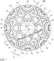
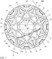
- a sheet metal section 100 is shown for a rotor of an electric machine.
- the sheet metal section 100 has a central connecting means 10, which as Retaining ring 11 is formed. Seen in a radial direction 12 to the outside closes to the connecting means 10 an inner region 13 at. Farther outward in the direction of the radial direction 12, an outer region 14 adjoins the inner region 13. Magnetic poles 16 are arranged in the outer region 14 in a circumferential direction 15.
- the illustrated sheet metal section 100 has eight magnetic poles 16.
- Each magnetic pole 16 includes a first magnet 17 and a second magnet 18, wherein the first magnet 17 and the second magnet 18 are aligned with each other in a V-shape. Furthermore, each magnetic pole 16 has a third magnet 19, which is arranged approximately in the circumferential direction 15 tangentially with respect to an outer circumference 20 of the sheet metal section 100. In Fig. 2 the magnets 17, 18, 19 are not shown.
- the inner region 13 has webs 21, which each connect two approximately opposite magnetic poles 16 or extend between each two approximately in opposite magnetic poles 16. For example, the web 21a connects a first magnetic pole 16a and a second magnetic pole 16b. Bridge 21a is in for better visibility Fig. 1 hatched shown.
- the webs 21 have, as shown on the web 21a, a plurality of web portions 22, which are arranged along the elongated extent of the web 21a one behind the other and are each at an angle.
- the magnetic poles 16 are arranged such that they lie on the vertices of a first imaginary n-corner 23. Since there are eight magnetic poles 16, the first n-corner 23 is formed as an octagon 23a, as in FIG Fig. 2 indicated by dashed lines.
- the webs 21 are arranged in the form of a folded-over polygon and define an n-star 24 formed as an asterisk 24a. For illustration purposes only, FIG Fig.
- connection means 10 designed as a retaining ring 11 is arranged in the second octagon 25a and connected to the web portions 26 bordering the second octagon 25a or the connecting means 11 is at least partially formed by the web portions 26 bordering the second octagon 25a.
- the webs 21 extend approximately tangentially to the connecting means 10 or to the retaining ring 11. As shown by the example of the web 21a, centrifugal forces and electromagnetic forces occurring during operation are transmitted along the webs 21 between a first magnetic pole 16a and a wide magnetic pole 16b.
- the power flow is thus to some extent passed past the connecting means 10 formed as a retaining ring 11, so that no or only small radial forces act on the retaining ring 11, or so that a tangential preferred direction for the forces on the retaining ring 11 is present and the radial forces are minimal.
- the retaining ring 11 has a circular receiving opening 27 for receiving a rotor shaft, not shown.
- the ratio of the width 28 of the inner region to the width 29 of the outer region is between 1.4 and 1.5.
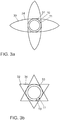
- n-stars 24 are shown, which are formed depending on the number of magnetic poles 16 of the webs 21.
- Fig. 3a schematically shows a four-star 30 having a inscribed square 31.
- Fig. 3b shows a six-star 32 with an inscribed hexagon 33 and arranged in the hexagon 33 retaining ring 11.
- Other n-star 24 as a ten-star (decagram) are also conceivable.
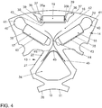
- Fig. 4 shows an octant of the sheet cut 100 of Fig. 1 and 2 , In the inner region 13 web portions 22 are arranged by webs 21. A portion of the connecting means 10 formed as a retaining ring 11 is connected to web portions 26. Between the webs 21 recesses 34 are arranged, which serve to reduce the weight of the sheet metal section 100.
- the in Fig. 4 Magnetic pole 16 shown comprises a first magnet 17, a second magnet 18 and a third magnet 19. On a first end side 35a of the third magnet 19 is formed as a wing-shaped Lucaskavmaschine 36 Magnetfeldleitstoff 37 is arranged. Another magnetic field guiding means 37 is arranged on a second end side 35b of the third magnet 19 in the form of a further wing-shaped air cavity 36.
- the magnets 17, 18, 19 are each arranged in a magnetic receptacle 38. Between the wing-shaped air cavities 36 and the magnetic receptacle 38 of the first magnet 19 Anlagenstege 39 are arranged. The Switzerlandstege 39 are aligned with each other in the direction of the outer periphery 20 inclined. Two further air cavities 40 are arranged on the end of the first magnet 17 and the second magnet 18 and have a wide rounded upper shoulder 41. First magnet 17, second magnet 18 and third magnet 19 define a reluctance path 42 for coupling an external stator field.
- Further magnetic field guiding means 37 in the form of air cavities 43 may be arranged laterally, in particular in the direction of the inner region 13 of the first magnet 17, the second magnet 18 and the third magnet 19, wherein the air cavities 43 are part of the magnet receptacles 38.
- a separating web 44th arranged between the first magnet 17 and the second magnet 18 , which serves for the power connection of the outer region 14 with the inner region 13. To illustrate the power flow are purely schematically lines of force 45 in Fig. 4 located.
- Fig. 5 shows a detailed view of a magnetic pole 16.
- the wing-shaped air cavities 36 on the first end face 35a and the second end face 35b of the third magnet 19 by pull bars 39 from the magnet holder 38 of the first magnet 19 is separated.
- the angle 46 between the V-shaped first magnet 17 and second magnet 18 is between 110 ° and 120 °.
- the magnetic receptacles 38 each have holding projections 47 for fixing the magnet 17, 18, 19.
- the largest distance 48 of the third magnet 19 from the outer periphery 29 of the sheet metal section 100 is 3.8 mm.
- the shortest distance 49 of the first magnet 17 and the second magnet 18 from the outer circumference 20 measured perpendicular to the third magnet 19 is 7.3 mm.
- the diameter 50 of the air cavity 40 end-mounted on the first magnet and the second magnet is 8 mm.
- the dimensions described above are exemplary only and deviations of any dimension in the range of 10% may occur.
- the distances 48, 49 and the diameter 50 are also scalable with the size of the sheet metal section 100, wherein preferably the relative ratios of these sizes are maintained relative to each other.
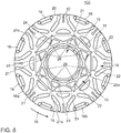
- the Fig. 6 shows a further plan view of a sheet cut 100.
- the sheet cut 100 of Fig. 1 and 2 has the brass section 100 of Fig. 6 eight magnetic poles 16 on.
- the n-star 24 formed by the webs 21 as octagons 24a is shaped differently.
- the shape of the sheet metal cut 100 eight-star 24a Fig. 6 is also known as the eighth place, which represents a special octagram.
- the comparison of Fig. 1 . 2 and 6 shows that in the case of the cut 100 of the Fig.
- each web connects a first magnetic pole 16a to a second magnetic pole 16b, two further magnetic poles 16 being arranged between the first magnetic pole 16a and the second magnetic pole 16b in the circumferential direction 15.
- Fig. 6 is seen in the circumferential direction 15 only one magnetic pole 16 between each of a web 21 connected to the first magnetic pole 16 a and second magnetic pole 16 b.
- Another difference of the sheet metal section 100 of the Fig. 6 to the brass section 100 of Fig. 1 and 2 is that in the cut 100 of the Fig. 6 formed as a retaining ring 11 connecting means 10 is connected via thin webs 51 with the second octagon 25a bordering web portions 26, whereas in the Fig. 1 and 2 the connecting means 10 is at least partially formed by the second octagon 25a bordering web portions 26.
- radial slots 52 may optionally be provided on the outer circumference 20 between the magnetic poles 16.
Applications Claiming Priority (1)
| Application Number | Priority Date | Filing Date | Title |
|---|---|---|---|
| DE102017209247.5A DE102017209247A1 (de) | 2017-05-31 | 2017-05-31 | Blechschnitt für einen Rotor einer elektrischen Maschine, Rotor für eine elektrische Maschine und elektrische Maschine mit Rotor |
Publications (2)
| Publication Number | Publication Date |
|---|---|
| EP3410571A1 true EP3410571A1 (fr) | 2018-12-05 |
| EP3410571B1 EP3410571B1 (fr) | 2021-04-07 |
Family
ID=61521369
Family Applications (1)
| Application Number | Title | Priority Date | Filing Date |
|---|---|---|---|
| EP18158946.6A Active EP3410571B1 (fr) | 2017-05-31 | 2018-02-27 | Lamelle de tôle pour un rotor d'une machine électrique, rotor pour une machine électrique et machine électrique pourvue de rotor |
Country Status (3)
| Country | Link |
|---|---|
| EP (1) | EP3410571B1 (fr) |
| CN (1) | CN108988526B (fr) |
| DE (1) | DE102017209247A1 (fr) |
Cited By (1)
| Publication number | Priority date | Publication date | Assignee | Title |
|---|---|---|---|---|
| WO2021043362A1 (fr) * | 2019-09-02 | 2021-03-11 | Schaeffler Technologies AG & Co. KG | Anneau en tôle pour un paquet de tôles rotoriques d'un rotor d'une machine électrique et procédé de fabrication d'un paquet de tôles rotoriques à partir de plusieurs anneaux en tôle |
Families Citing this family (7)
| Publication number | Priority date | Publication date | Assignee | Title |
|---|---|---|---|---|
| DE102019207883A1 (de) | 2019-05-29 | 2020-12-03 | Robert Bosch Gmbh | Rotor einer elektrischen Maschine |
| DE102019123433A1 (de) * | 2019-09-02 | 2021-03-04 | Schaeffler Technologies AG & Co. KG | Rotorblechpaket für einen Rotor und Verfahren zur Herstellung eines Rotorblechpakets |
| DE102020108830A1 (de) * | 2020-03-31 | 2021-09-30 | Schaeffler Technologies AG & Co. KG | Blech eines Blechpakets sowie Rotor einer elektrischen Rotationsmaschine mit mehreren Blechen |
| DE102020113938A1 (de) | 2020-05-25 | 2021-09-02 | Audi Aktiengesellschaft | Blechpaket für eine permanenterregte Synchronmaschine mit vergrößerten Magnettaschen zum Erhöhen eines Drehmoments durch Reluktanz sowie Synchronmaschine und Kraftfahrzeug |
| DE102020115286A1 (de) | 2020-06-09 | 2021-12-09 | Schaeffler Technologies AG & Co. KG | Elektromotor mit Aufnahmetaschen zur Aufnahme von Magneten |
| DE102020214035A1 (de) * | 2020-11-09 | 2022-05-12 | Robert Bosch Gesellschaft mit beschränkter Haftung | Rotor einer elektrischen Maschine mit mehrschichtiger Permanentmagnetanordnung |
| DE102022210312A1 (de) | 2022-09-29 | 2024-04-04 | Brose Fahrzeugteile SE & Co. Kommanditgesellschaft, Würzburg | Blechpaket für einen Rotor |
Citations (3)
| Publication number | Priority date | Publication date | Assignee | Title |
|---|---|---|---|---|
| US20120200186A1 (en) * | 2011-02-03 | 2012-08-09 | Toyota Jidosha Kabushiki Kaisha | Rotor for electric rotating machine |
| DE102013201199A1 (de) * | 2013-01-25 | 2014-07-31 | Magna Powertrain Ag & Co. Kg | Elektrische Maschine und Verfahren zur Herstellung eines Elektroblechs |
| US20160233733A1 (en) * | 2015-02-10 | 2016-08-11 | Zero Motorcycles, Inc. | Reduced Weight Rotor Having Structural Integrity |
Family Cites Families (4)
| Publication number | Priority date | Publication date | Assignee | Title |
|---|---|---|---|---|
| DE10126340A1 (de) * | 2001-05-30 | 2002-12-12 | Siemens Ag | Elektrische Maschine mit trägheitsarmen Läufer |
| JP4668721B2 (ja) | 2004-11-30 | 2011-04-13 | 日立オートモティブシステムズ株式会社 | 永久磁石式回転電機 |
| DE102010050934A1 (de) * | 2010-10-29 | 2012-05-03 | Sew-Eurodrive Gmbh & Co. Kg | Elektromotor, Verfahren zum Herstellen eines Rotors eines Elektromotors und Verwendung |
| US20140283373A1 (en) * | 2011-12-19 | 2014-09-25 | Baldor Electric Company | Lamination for a Permanent Magnet Machine |
-
2017
- 2017-05-31 DE DE102017209247.5A patent/DE102017209247A1/de not_active Withdrawn
-
2018
- 2018-02-27 EP EP18158946.6A patent/EP3410571B1/fr active Active
- 2018-05-31 CN CN201810547384.7A patent/CN108988526B/zh active Active
Patent Citations (3)
| Publication number | Priority date | Publication date | Assignee | Title |
|---|---|---|---|---|
| US20120200186A1 (en) * | 2011-02-03 | 2012-08-09 | Toyota Jidosha Kabushiki Kaisha | Rotor for electric rotating machine |
| DE102013201199A1 (de) * | 2013-01-25 | 2014-07-31 | Magna Powertrain Ag & Co. Kg | Elektrische Maschine und Verfahren zur Herstellung eines Elektroblechs |
| US20160233733A1 (en) * | 2015-02-10 | 2016-08-11 | Zero Motorcycles, Inc. | Reduced Weight Rotor Having Structural Integrity |
Cited By (3)
| Publication number | Priority date | Publication date | Assignee | Title |
|---|---|---|---|---|
| WO2021043362A1 (fr) * | 2019-09-02 | 2021-03-11 | Schaeffler Technologies AG & Co. KG | Anneau en tôle pour un paquet de tôles rotoriques d'un rotor d'une machine électrique et procédé de fabrication d'un paquet de tôles rotoriques à partir de plusieurs anneaux en tôle |
| CN114287097A (zh) * | 2019-09-02 | 2022-04-05 | 舍弗勒技术股份两合公司 | 用于电机的转子的叠层转子芯的叠片环以及用于制造由多个叠片环制成的叠层转子芯的方法 |
| US20220329121A1 (en) * | 2019-09-02 | 2022-10-13 | Schaeffler Technologies AG & Co. KG | Lamination ring for a laminated rotor core of a rotor of an electric machine, and method for producing a laminated rotor core made of multiple lamination rings |
Also Published As
| Publication number | Publication date |
|---|---|
| DE102017209247A1 (de) | 2018-12-06 |
| CN108988526A (zh) | 2018-12-11 |
| EP3410571B1 (fr) | 2021-04-07 |
| CN108988526B (zh) | 2021-04-20 |
Similar Documents
| Publication | Publication Date | Title |
|---|---|---|
| EP3410571B1 (fr) | Lamelle de tôle pour un rotor d'une machine électrique, rotor pour une machine électrique et machine électrique pourvue de rotor | |
| DE112014000526B4 (de) | Rotor und drehende elektrische Maschine, die diesen Rotor enthält | |
| DE102013209344B4 (de) | Magnetische barriere zum minimieren der entmagnetisierung bei synchronmaschinen mit bi-permanentmagneten | |
| DE112018003942T5 (de) | Magnetische Erzeugungseinrichtung für einen Motor, Weichmagnetischer Kern und Verfahren zur Herstellung eines Magneten | |
| EP3520199B1 (fr) | Machine électrique comportant un rotor et un stator | |
| DE102016125708A1 (de) | Motor | |
| EP1746707A1 (fr) | Moteur synchrone à aimants permanents sans balais avec rotor à aimants incorporés et force contre-électromotrice trapézoidale | |
| DE102017113193A1 (de) | Elektrischer Maschinenrotor | |
| DE102013213554A1 (de) | Elektrische permanentmagnet-rotationsmaschine | |
| DE102013021110A1 (de) | Rotor eines Synchronmotors mit internen Permanentmagneten und Synchronmotor mit internen Permanentmagneten | |
| DE102012001118B4 (de) | Elektromaschine | |
| DE112017004455T5 (de) | Rotor für rotierende elektrische maschine und verfahren zum herstellen einer rotierenden elektrischen maschine | |
| EP3949083A1 (fr) | Moteur à réluctance synchrone à quatre pôles | |
| DE102019107452A1 (de) | Rotor und elektrische Maschine | |
| DE102016008686A1 (de) | Kernkörper für Statoren und/oder Rotoren von elektrischen Maschinen, Stator/Rotor mit einem solchen Kernkörper sowie elektrische Maschine mit einem solchen Kernkörper | |
| WO2014005580A2 (fr) | Élément d'une machine électrique comportant une fixation et un aimant permanent, composant comportant au moins un élément et machine électrique | |
| DE112017000584T5 (de) | Rotor und Verfahren zur Auslegung des Rotors | |
| DE102017205021A1 (de) | Polschuh, elektrische maschine und fahrzeug | |
| DE112019007887T5 (de) | Rotierende elektrische maschine | |
| WO2017012765A1 (fr) | Machine électrique à excitation permanente avec géométrie optimisée | |
| EP2705590B1 (fr) | Rotor pour une maschine à aimants permanents | |
| WO2019154573A1 (fr) | Machine synchrone à excitation continue ayant un couple pendulaire réduit | |
| EP3154176B1 (fr) | Moteur d'entraînement électrique | |
| DE102017201029A1 (de) | Rotor für elektrische Maschine | |
| DE102020113938A1 (de) | Blechpaket für eine permanenterregte Synchronmaschine mit vergrößerten Magnettaschen zum Erhöhen eines Drehmoments durch Reluktanz sowie Synchronmaschine und Kraftfahrzeug |
Legal Events
| Date | Code | Title | Description |
|---|---|---|---|
| PUAI | Public reference made under article 153(3) epc to a published international application that has entered the european phase |
Free format text: ORIGINAL CODE: 0009012 |
|
| STAA | Information on the status of an ep patent application or granted ep patent |
Free format text: STATUS: THE APPLICATION HAS BEEN PUBLISHED |
|
| AK | Designated contracting states |
Kind code of ref document: A1 Designated state(s): AL AT BE BG CH CY CZ DE DK EE ES FI FR GB GR HR HU IE IS IT LI LT LU LV MC MK MT NL NO PL PT RO RS SE SI SK SM TR |
|
| AX | Request for extension of the european patent |
Extension state: BA ME |
|
| STAA | Information on the status of an ep patent application or granted ep patent |
Free format text: STATUS: REQUEST FOR EXAMINATION WAS MADE |
|
| 17P | Request for examination filed |
Effective date: 20190605 |
|
| RBV | Designated contracting states (corrected) |
Designated state(s): AL AT BE BG CH CY CZ DE DK EE ES FI FR GB GR HR HU IE IS IT LI LT LU LV MC MK MT NL NO PL PT RO RS SE SI SK SM TR |
|
| STAA | Information on the status of an ep patent application or granted ep patent |
Free format text: STATUS: EXAMINATION IS IN PROGRESS |
|
| 17Q | First examination report despatched |
Effective date: 20200212 |
|
| GRAP | Despatch of communication of intention to grant a patent |
Free format text: ORIGINAL CODE: EPIDOSNIGR1 |
|
| STAA | Information on the status of an ep patent application or granted ep patent |
Free format text: STATUS: GRANT OF PATENT IS INTENDED |
|
| INTG | Intention to grant announced |
Effective date: 20201014 |
|
| GRAS | Grant fee paid |
Free format text: ORIGINAL CODE: EPIDOSNIGR3 |
|
| GRAA | (expected) grant |
Free format text: ORIGINAL CODE: 0009210 |
|
| STAA | Information on the status of an ep patent application or granted ep patent |
Free format text: STATUS: THE PATENT HAS BEEN GRANTED |
|
| AK | Designated contracting states |
Kind code of ref document: B1 Designated state(s): AL AT BE BG CH CY CZ DE DK EE ES FI FR GB GR HR HU IE IS IT LI LT LU LV MC MK MT NL NO PL PT RO RS SE SI SK SM TR |
|
| REG | Reference to a national code |
Ref country code: GB Ref legal event code: FG4D Free format text: NOT ENGLISH |
|
| REG | Reference to a national code |
Ref country code: AT Ref legal event code: REF Ref document number: 1380956 Country of ref document: AT Kind code of ref document: T Effective date: 20210415 Ref country code: CH Ref legal event code: EP |
|
| REG | Reference to a national code |
Ref country code: DE Ref legal event code: R096 Ref document number: 502018004609 Country of ref document: DE |
|
| REG | Reference to a national code |
Ref country code: IE Ref legal event code: FG4D Free format text: LANGUAGE OF EP DOCUMENT: GERMAN |
|
| REG | Reference to a national code |
Ref country code: LT Ref legal event code: MG9D |
|
| REG | Reference to a national code |
Ref country code: NL Ref legal event code: MP Effective date: 20210407 |
|
| PG25 | Lapsed in a contracting state [announced via postgrant information from national office to epo] |
Ref country code: NL Free format text: LAPSE BECAUSE OF FAILURE TO SUBMIT A TRANSLATION OF THE DESCRIPTION OR TO PAY THE FEE WITHIN THE PRESCRIBED TIME-LIMIT Effective date: 20210407 Ref country code: HR Free format text: LAPSE BECAUSE OF FAILURE TO SUBMIT A TRANSLATION OF THE DESCRIPTION OR TO PAY THE FEE WITHIN THE PRESCRIBED TIME-LIMIT Effective date: 20210407 Ref country code: BG Free format text: LAPSE BECAUSE OF FAILURE TO SUBMIT A TRANSLATION OF THE DESCRIPTION OR TO PAY THE FEE WITHIN THE PRESCRIBED TIME-LIMIT Effective date: 20210707 Ref country code: LT Free format text: LAPSE BECAUSE OF FAILURE TO SUBMIT A TRANSLATION OF THE DESCRIPTION OR TO PAY THE FEE WITHIN THE PRESCRIBED TIME-LIMIT Effective date: 20210407 Ref country code: FI Free format text: LAPSE BECAUSE OF FAILURE TO SUBMIT A TRANSLATION OF THE DESCRIPTION OR TO PAY THE FEE WITHIN THE PRESCRIBED TIME-LIMIT Effective date: 20210407 |
|
| PG25 | Lapsed in a contracting state [announced via postgrant information from national office to epo] |
Ref country code: RS Free format text: LAPSE BECAUSE OF FAILURE TO SUBMIT A TRANSLATION OF THE DESCRIPTION OR TO PAY THE FEE WITHIN THE PRESCRIBED TIME-LIMIT Effective date: 20210407 Ref country code: SE Free format text: LAPSE BECAUSE OF FAILURE TO SUBMIT A TRANSLATION OF THE DESCRIPTION OR TO PAY THE FEE WITHIN THE PRESCRIBED TIME-LIMIT Effective date: 20210407 Ref country code: LV Free format text: LAPSE BECAUSE OF FAILURE TO SUBMIT A TRANSLATION OF THE DESCRIPTION OR TO PAY THE FEE WITHIN THE PRESCRIBED TIME-LIMIT Effective date: 20210407 Ref country code: PT Free format text: LAPSE BECAUSE OF FAILURE TO SUBMIT A TRANSLATION OF THE DESCRIPTION OR TO PAY THE FEE WITHIN THE PRESCRIBED TIME-LIMIT Effective date: 20210809 Ref country code: NO Free format text: LAPSE BECAUSE OF FAILURE TO SUBMIT A TRANSLATION OF THE DESCRIPTION OR TO PAY THE FEE WITHIN THE PRESCRIBED TIME-LIMIT Effective date: 20210707 Ref country code: PL Free format text: LAPSE BECAUSE OF FAILURE TO SUBMIT A TRANSLATION OF THE DESCRIPTION OR TO PAY THE FEE WITHIN THE PRESCRIBED TIME-LIMIT Effective date: 20210407 Ref country code: GR Free format text: LAPSE BECAUSE OF FAILURE TO SUBMIT A TRANSLATION OF THE DESCRIPTION OR TO PAY THE FEE WITHIN THE PRESCRIBED TIME-LIMIT Effective date: 20210708 Ref country code: IS Free format text: LAPSE BECAUSE OF FAILURE TO SUBMIT A TRANSLATION OF THE DESCRIPTION OR TO PAY THE FEE WITHIN THE PRESCRIBED TIME-LIMIT Effective date: 20210807 |
|
| REG | Reference to a national code |
Ref country code: DE Ref legal event code: R097 Ref document number: 502018004609 Country of ref document: DE |
|
| PG25 | Lapsed in a contracting state [announced via postgrant information from national office to epo] |
Ref country code: SM Free format text: LAPSE BECAUSE OF FAILURE TO SUBMIT A TRANSLATION OF THE DESCRIPTION OR TO PAY THE FEE WITHIN THE PRESCRIBED TIME-LIMIT Effective date: 20210407 Ref country code: SK Free format text: LAPSE BECAUSE OF FAILURE TO SUBMIT A TRANSLATION OF THE DESCRIPTION OR TO PAY THE FEE WITHIN THE PRESCRIBED TIME-LIMIT Effective date: 20210407 Ref country code: EE Free format text: LAPSE BECAUSE OF FAILURE TO SUBMIT A TRANSLATION OF THE DESCRIPTION OR TO PAY THE FEE WITHIN THE PRESCRIBED TIME-LIMIT Effective date: 20210407 Ref country code: ES Free format text: LAPSE BECAUSE OF FAILURE TO SUBMIT A TRANSLATION OF THE DESCRIPTION OR TO PAY THE FEE WITHIN THE PRESCRIBED TIME-LIMIT Effective date: 20210407 Ref country code: RO Free format text: LAPSE BECAUSE OF FAILURE TO SUBMIT A TRANSLATION OF THE DESCRIPTION OR TO PAY THE FEE WITHIN THE PRESCRIBED TIME-LIMIT Effective date: 20210407 Ref country code: CZ Free format text: LAPSE BECAUSE OF FAILURE TO SUBMIT A TRANSLATION OF THE DESCRIPTION OR TO PAY THE FEE WITHIN THE PRESCRIBED TIME-LIMIT Effective date: 20210407 Ref country code: DK Free format text: LAPSE BECAUSE OF FAILURE TO SUBMIT A TRANSLATION OF THE DESCRIPTION OR TO PAY THE FEE WITHIN THE PRESCRIBED TIME-LIMIT Effective date: 20210407 |
|
| PLBE | No opposition filed within time limit |
Free format text: ORIGINAL CODE: 0009261 |
|
| STAA | Information on the status of an ep patent application or granted ep patent |
Free format text: STATUS: NO OPPOSITION FILED WITHIN TIME LIMIT |
|
| 26N | No opposition filed |
Effective date: 20220110 |
|
| PG25 | Lapsed in a contracting state [announced via postgrant information from national office to epo] |
Ref country code: IS Free format text: LAPSE BECAUSE OF FAILURE TO SUBMIT A TRANSLATION OF THE DESCRIPTION OR TO PAY THE FEE WITHIN THE PRESCRIBED TIME-LIMIT Effective date: 20210807 Ref country code: AL Free format text: LAPSE BECAUSE OF FAILURE TO SUBMIT A TRANSLATION OF THE DESCRIPTION OR TO PAY THE FEE WITHIN THE PRESCRIBED TIME-LIMIT Effective date: 20210407 |
|
| PG25 | Lapsed in a contracting state [announced via postgrant information from national office to epo] |
Ref country code: MC Free format text: LAPSE BECAUSE OF FAILURE TO SUBMIT A TRANSLATION OF THE DESCRIPTION OR TO PAY THE FEE WITHIN THE PRESCRIBED TIME-LIMIT Effective date: 20210407 |
|
| REG | Reference to a national code |
Ref country code: CH Ref legal event code: PL |
|
| REG | Reference to a national code |
Ref country code: BE Ref legal event code: MM Effective date: 20220228 |
|
| PG25 | Lapsed in a contracting state [announced via postgrant information from national office to epo] |
Ref country code: LU Free format text: LAPSE BECAUSE OF NON-PAYMENT OF DUE FEES Effective date: 20220227 |
|
| PG25 | Lapsed in a contracting state [announced via postgrant information from national office to epo] |
Ref country code: LI Free format text: LAPSE BECAUSE OF NON-PAYMENT OF DUE FEES Effective date: 20220228 Ref country code: IE Free format text: LAPSE BECAUSE OF NON-PAYMENT OF DUE FEES Effective date: 20220227 Ref country code: CH Free format text: LAPSE BECAUSE OF NON-PAYMENT OF DUE FEES Effective date: 20220228 |
|
| PG25 | Lapsed in a contracting state [announced via postgrant information from national office to epo] |
Ref country code: BE Free format text: LAPSE BECAUSE OF NON-PAYMENT OF DUE FEES Effective date: 20220228 |
|
| PGFP | Annual fee paid to national office [announced via postgrant information from national office to epo] |
Ref country code: FR Payment date: 20230223 Year of fee payment: 6 |
|
| PGFP | Annual fee paid to national office [announced via postgrant information from national office to epo] |
Ref country code: IT Payment date: 20230220 Year of fee payment: 6 |
|
| P01 | Opt-out of the competence of the unified patent court (upc) registered |
Effective date: 20230523 |
|
| PG25 | Lapsed in a contracting state [announced via postgrant information from national office to epo] |
Ref country code: HU Free format text: LAPSE BECAUSE OF FAILURE TO SUBMIT A TRANSLATION OF THE DESCRIPTION OR TO PAY THE FEE WITHIN THE PRESCRIBED TIME-LIMIT; INVALID AB INITIO Effective date: 20180227 |
|
| REG | Reference to a national code |
Ref country code: AT Ref legal event code: MM01 Ref document number: 1380956 Country of ref document: AT Kind code of ref document: T Effective date: 20230227 |
|
| PG25 | Lapsed in a contracting state [announced via postgrant information from national office to epo] |
Ref country code: AT Free format text: LAPSE BECAUSE OF NON-PAYMENT OF DUE FEES Effective date: 20230227 |
|
| PG25 | Lapsed in a contracting state [announced via postgrant information from national office to epo] |
Ref country code: MK Free format text: LAPSE BECAUSE OF FAILURE TO SUBMIT A TRANSLATION OF THE DESCRIPTION OR TO PAY THE FEE WITHIN THE PRESCRIBED TIME-LIMIT Effective date: 20210407 Ref country code: CY Free format text: LAPSE BECAUSE OF FAILURE TO SUBMIT A TRANSLATION OF THE DESCRIPTION OR TO PAY THE FEE WITHIN THE PRESCRIBED TIME-LIMIT Effective date: 20210407 Ref country code: AT Free format text: LAPSE BECAUSE OF NON-PAYMENT OF DUE FEES Effective date: 20230227 |
|
| PGFP | Annual fee paid to national office [announced via postgrant information from national office to epo] |
Ref country code: DE Payment date: 20240229 Year of fee payment: 7 Ref country code: GB Payment date: 20240220 Year of fee payment: 7 |