EP3410392A1 - Image processing system and medical information processing system - Google Patents
Image processing system and medical information processing system Download PDFInfo
- Publication number
- EP3410392A1 EP3410392A1 EP18175395.5A EP18175395A EP3410392A1 EP 3410392 A1 EP3410392 A1 EP 3410392A1 EP 18175395 A EP18175395 A EP 18175395A EP 3410392 A1 EP3410392 A1 EP 3410392A1
- Authority
- EP
- European Patent Office
- Prior art keywords
- image
- neural network
- input
- processing system
- noise
- Prior art date
- Legal status (The legal status is an assumption and is not a legal conclusion. Google has not performed a legal analysis and makes no representation as to the accuracy of the status listed.)
- Granted
Links
- 238000012545 processing Methods 0.000 title claims abstract description 163
- 230000010365 information processing Effects 0.000 title claims description 6
- 238000013528 artificial neural network Methods 0.000 claims abstract description 159
- 238000012549 training Methods 0.000 claims abstract description 75
- 230000006870 function Effects 0.000 claims description 121
- 230000004913 activation Effects 0.000 claims description 29
- 238000000034 method Methods 0.000 claims description 17
- 230000008569 process Effects 0.000 claims description 12
- 238000003384 imaging method Methods 0.000 claims description 8
- 238000010586 diagram Methods 0.000 description 31
- 230000009467 reduction Effects 0.000 description 16
- 238000010801 machine learning Methods 0.000 description 8
- 238000010606 normalization Methods 0.000 description 8
- 230000000694 effects Effects 0.000 description 6
- 238000002595 magnetic resonance imaging Methods 0.000 description 6
- 238000013459 approach Methods 0.000 description 3
- 230000006866 deterioration Effects 0.000 description 3
- 102100035353 Cyclin-dependent kinase 2-associated protein 1 Human genes 0.000 description 2
- 101000661816 Homo sapiens Suppression of tumorigenicity 18 protein Proteins 0.000 description 2
- 230000003044 adaptive effect Effects 0.000 description 2
- 238000004422 calculation algorithm Methods 0.000 description 2
- 238000004364 calculation method Methods 0.000 description 2
- 230000007423 decrease Effects 0.000 description 2
- 210000005036 nerve Anatomy 0.000 description 2
- 230000003287 optical effect Effects 0.000 description 2
- 238000002360 preparation method Methods 0.000 description 2
- 238000012706 support-vector machine Methods 0.000 description 2
- 238000012795 verification Methods 0.000 description 2
- 101000911772 Homo sapiens Hsc70-interacting protein Proteins 0.000 description 1
- 101001139126 Homo sapiens Krueppel-like factor 6 Proteins 0.000 description 1
- 102100029860 Suppressor of tumorigenicity 20 protein Human genes 0.000 description 1
- 230000008859 change Effects 0.000 description 1
- 238000004891 communication Methods 0.000 description 1
- 238000003066 decision tree Methods 0.000 description 1
- 238000005516 engineering process Methods 0.000 description 1
- 230000010354 integration Effects 0.000 description 1
- 238000012417 linear regression Methods 0.000 description 1
- 239000004973 liquid crystal related substance Substances 0.000 description 1
- 238000012986 modification Methods 0.000 description 1
- 230000004048 modification Effects 0.000 description 1
- 238000007637 random forest analysis Methods 0.000 description 1
- 238000006467 substitution reaction Methods 0.000 description 1
- 238000003325 tomography Methods 0.000 description 1
Images


Classifications
-
- G06T5/70—
-
- G—PHYSICS
- G06—COMPUTING; CALCULATING OR COUNTING
- G06N—COMPUTING ARRANGEMENTS BASED ON SPECIFIC COMPUTATIONAL MODELS
- G06N3/00—Computing arrangements based on biological models
- G06N3/02—Neural networks
- G06N3/04—Architecture, e.g. interconnection topology
- G06N3/048—Activation functions
-
- G—PHYSICS
- G06—COMPUTING; CALCULATING OR COUNTING
- G06N—COMPUTING ARRANGEMENTS BASED ON SPECIFIC COMPUTATIONAL MODELS
- G06N3/00—Computing arrangements based on biological models
- G06N3/02—Neural networks
- G06N3/04—Architecture, e.g. interconnection topology
- G06N3/045—Combinations of networks
-
- G—PHYSICS
- G06—COMPUTING; CALCULATING OR COUNTING
- G06N—COMPUTING ARRANGEMENTS BASED ON SPECIFIC COMPUTATIONAL MODELS
- G06N3/00—Computing arrangements based on biological models
- G06N3/02—Neural networks
- G06N3/08—Learning methods
- G06N3/084—Backpropagation, e.g. using gradient descent
-
- G06T5/60—
-
- G—PHYSICS
- G16—INFORMATION AND COMMUNICATION TECHNOLOGY [ICT] SPECIALLY ADAPTED FOR SPECIFIC APPLICATION FIELDS
- G16H—HEALTHCARE INFORMATICS, i.e. INFORMATION AND COMMUNICATION TECHNOLOGY [ICT] SPECIALLY ADAPTED FOR THE HANDLING OR PROCESSING OF MEDICAL OR HEALTHCARE DATA
- G16H30/00—ICT specially adapted for the handling or processing of medical images
- G16H30/40—ICT specially adapted for the handling or processing of medical images for processing medical images, e.g. editing
-
- G—PHYSICS
- G06—COMPUTING; CALCULATING OR COUNTING
- G06T—IMAGE DATA PROCESSING OR GENERATION, IN GENERAL
- G06T2207/00—Indexing scheme for image analysis or image enhancement
- G06T2207/20—Special algorithmic details
- G06T2207/20084—Artificial neural networks [ANN]
-
- G—PHYSICS
- G06—COMPUTING; CALCULATING OR COUNTING
- G06T—IMAGE DATA PROCESSING OR GENERATION, IN GENERAL
- G06T2207/00—Indexing scheme for image analysis or image enhancement
- G06T2207/30—Subject of image; Context of image processing
- G06T2207/30004—Biomedical image processing
Definitions
- Embodiments described herein relate generally to an image processing system and a medical information processing system.
- the neural network is a processing device in which one or more nodes simulating cells are connected by one or more edges that simulate nerves.
- the neural network has biases and weighting coefficients, both of which are associated with respective edges, as its internal parameters.
- each node has an activation function, and the parameters of the activation function are also included in the internal parameters of the neural network.
- Machine learning is used for calculating the internal parameters of the neural network. For instance, in a neural network aimed at removing noise of an image, the internal parameters are generally calculated in the following manner.
- initial setting is manually performed on various conditions such as connection relationship between respective nodes, initial values of the biases and weighting coefficients associated with respective edges, and an initial value of the parameter of the activation function in each node.
- an image without noise i.e., a "ground truth”
- a “training image” in which noise is artificially superimposed on the ground truth are prepared.
- the initial parameters of the neural network are sequentially updated in such a manner that the difference between the training image processed in the neural network and the ground truth becomes smaller. Such a series of processing flow is called "training”.
- a noise-superimposed image in which actual noise is superimposed is inputted to a neural network having internal parameters calculated by the training, and an image in which noise is removed or reduced is obtained at the output of the neural network.
- the noise removal performance or noise reduction performance is obtained, when the amount of superimposed noise in the noise-superimposed image to be used is as large as the amount of noise in the training image, which has been used in the training process.
- the noise removal performance or noise reduction performance may deteriorate when the amount of noise in the noise-superimposed image to be used is different from the amount of noise in the training image.
- an approach may be considered in which plural training images, that have noise amounts different from each other, are used when training the internal parameters in the neural network, instead of using training images having a noise amount of a single magnitude.
- the noise removal or noise reduction performance may be reduced, compared with the noise removal or reduction performance obtained by using the training images that have a noise amount of a single magnitude.
- an image processing system includes a memory and processing circuitry.
- the memory is configured to store a predetermined program.
- the processing circuitry is configured, by executing the predetermined program, to perform processing on an input image by exploiting a neural network having an input layer, an output layer, and an intermediate layer provided between the input layer and the output layer, the input image being inputted to the input layer, and adjust an internal parameter based on data related to the input image, while performing the processing on the input image after training of the neural network, the internal parameter being at least one internal parameter of at least one node included in the intermediate layer, and the input parameter having been calculated by the training of the neural network.
- Fig. 1 is a block diagram illustrating an overall configuration of an image processing system 100 according to the first embodiment.
- the image processing system 100 is constituted by, e.g., a computer system.
- the image processing system 100 includes processing circuitry 10, an input I/F (interface) 11, an output I/F (interface) 12,, a memory 21, a display 22, and an input device 23.
- the processing circuitry 10 is, e.g., a circuit equipped with a central processing unit (CPU) and/or a special-purpose or general-purpose processor.
- the processor implements various functions described below by executing programs stored in the memory 21.
- the processing circuitry 10 may be configured as hardware such as a field programmable gate array (FPGA) or an application specific integrated circuit (ASIC).
- FPGA field programmable gate array
- ASIC application specific integrated circuit
- the various functions described below can also be implemented by such hardware. Additionally, the processing circuitry 10 can implement the various functions by combining hardware processing and software processing based on its processor and programs.
- the memory 21 is a recording medium including a read-only memory (ROM), a random access memory (RAM), and an external memory device such as a hard disk drive (HDD) or an optical disc device.
- the memory 21 stores various programs executed by a processor of the processing circuitry 10 as well as various types of data and information.
- the input device 23 includes various devices for an operator to input various types of information and data, and is configured as, e.g., a mouse, a keyboard, a trackball, and/or a touch panel.
- the display 22 is a display device such as a liquid crystal display panel, a plasma display panel, and an organic EL panel.
- the input I/F 11 and the output I/F 12 are interfaces for inputting and outputting images, respectively.
- Each of the input I/F 11 and the output I/F 12 may include various devices and circuits such as a wired or wireless LAN, various communication interfaces including a USB, a network interface including the Internet and a public telephone line, and a drive circuit of various storage media including an optical disk and a magnetic disk.
- the input I/F 11 and the output I/F 12 can input and output image data, respectively.
- the processing circuitry 10 implements a parameter learning function 20, a neural-network processing function 30, an SNR-related data acquisition function 40, and a parameter adjustment function 50 by, e.g., executing various programs stored in the memory 21.
- the parameter learning function 20 determines respective values of internal parameters of the neural network 60 by machine learning (hereinafter, simply referred to as learning) with the use of a training image, as described below.
- the neural-network processing function 30 performs a predetermined processing on the input image inputted to the neural network 60 after training, by using the neural network 60.
- the SNR-related data acquisition function 40 acquires at least one of signal strength of the input image, magnitude of noise in the input image, signal-to-noise ratio (SNR) of the input image, gain used in normalization processing, data related to the signal-to-noise ratio, from the input image or supplementary information of the input image (hereinafter, the data acquired by the SNR-related data acquisition function are referred to as "SNR-related data").
- SNR-related data are data related to the input image.
- the parameter adjustment function 50 adjusts the respective values of the internal parameters of the neural network 60 on the basis of the SNR-related data acquired by the SNR-related data acquisition function 40, when the neural-network processing function 30 performs the predetermined processing on the input image inputted to the neural network 60 after training.
- the neural-network processing function 30 As to the parameter learning function 20, the neural-network processing function 30, the SNR-related data acquisition function 40, and the parameter adjustment function 50, their details will be described below.
- Fig. 2 is a schematic diagram illustrating an internal configuration of the neural network 60. Although the internal parameters are adjustable in the image processing system 100 according to the first embodiment, Fig. 2 illustrates only the basic configuration for avoiding complication and omits the configuration portion that can adjust the internal parameters.
- the neural network 60 has a multilayer structure that includes an input layer 61, an output layer 63, and at least one intermediate layer 62 between the input layer 61 and the output layer 63.
- the input layer 61 includes plural input terminals 70.
- the image processing system 100 of the present embodiment performs image processing such as noise reduction processing or noise removal processing by using the neural network 60.
- image data are inputted to the input layer 61.
- pixel signals constituting image data are inputted to the respective input terminals 70 of the input layer 61.
- the output layer 63 also has plural output terminals 90.
- the image data subjected to the image processing are outputted from the output layer 63.
- pixel signals of the image data subjected to the image processing are outputted to the respective output terminals 90 of the output layer 63.
- Each of the intermediate layers 62 includes plural nodes 80. Focusing on one intermediate layer 62 between other intermediate layers 62, the output signals of the plural nodes 80 of the immediately preceding intermediate layer 62 are inputted to each node 80 of the focused intermediate layer 62, and an output signal of each node 80 of the focused intermediate layer 62 is distributed to plural nodes 80 of the immediately subsequent intermediate layer 62.
- Fig. 3 is a schematic diagram illustrating an internal configuration of the node 80.
- Fig. 3 illustrates a node 80 in the intermediate layer 62 that is immediately subsequent to the input layer 61, other nodes in the intermediate layer 62 may have the same configuration.
- Plural signals are inputted to the node 80 shown in Fig. 3 .
- Respective input signals are subjected to weighting with weights 800 through the multipliers 801, and then summed up by an adder 802.
- an adder 804 adds a bias 803 to the output of the adder, and then, the output of the adder 804 is sent to the activation function 805.
- "x" is expressed by the following equation (1).
- x ⁇ i w i s i + b
- the output of the node 80 is determined.
- Various subdifferentiable functions such as a clipping function expressed by the equation (2), a ReLU function expressed by the equation (3), or a tanh function expressed by the equation (4), have been conventionally used.
- the Soft-Shrinkage function expressed by the following equation (5) may be used as the activation function 805.
- the Soft-Shrinkage function will be described below.
- the internal parameters of the conventional neural network 60 are determined by learning performed in advance. Then, when exploiting the neural network 60, i.e., when using the neural network 60, the respective determined values of the internal parameters are used in a fixed state.
- the respective values of the internal parameters of the neural network 60 can be adjusted on the basis of data related to the input image, when predetermined processing is performed after training, i.e., when the neural network 60 is exploited after training.
- Fig. 4 is a schematic diagram illustrating connection relationship between (a) the neural network 60 of the present embodiment configured to be able to adjust the internal parameters and (b) the parameter adjustment function 50 and the SNR-related data acquisition function 40 providing a control signal to the neural network 60.
- the parameter adjustment function 50 supplies the control signal to at least some nodes 80 of the intermediate layers 62.
- the parameter adjustment function 50 supplies a control signal to the nodes 80 of at least one intermediate layer 62.
- the control signal may be supplied from the parameter adjustment function 50 to each node 80 of the intermediate layers 62.
- Fig. 5 is a block diagram illustrating an internal configuration of one node 80 of the present embodiment.
- the node 80 shown in Fig. 5 is configured such that threshold T, which is the parameter of the activation function 805 (i.e., one of the internal parameters of the node 80), is adjusted with respect to the activation function 805.
- Fig. 6A is a graph illustrating a Soft-shrinkage function F SS (x, T) as an example of the activation function 805 in which the threshold T is used as a parameter.
- Fig. 6B is a graph illustrating a Hard-Shrinkage function F HS (x, T) as an example of the activation function 805 in which the threshold T is used as a parameter.
- Each of the Soft-Shrinkage function F SS (x, T) and the Hard-Shrinkage function F HS (x, T) is a function that outputs zero when an input value lies within a predetermined positive/negative threshold ⁇ T around zero, and outputs a value proportional to an input value when an input value lies outside the range of the threshold ⁇ T.
- the amplitude of the output of the Soft-Shrinkage function F SS (x, T) becomes smaller than the amplitude "x" of the input by the threshold T.
- the amplitude of the output of the Hard-Shrinkage function F HS (x, T) has the same value as the amplitude "x" of the input, when the input is out of the range of the threshold ⁇ T.
- the neural network 60 which uses the Soft-Shrinkage function F SS (x, T) or the Hard-Shrinkage function F HS (x, T) as the activation function 805, is a technology for reducing noise in an image and exerts a noise reduction effect when the threshold value T is set to an appropriate magnitude with respect to the noise level.
- the SNR-related data acquisition function 40 acquires data related to SNR or magnitude of noise of the input image (i.e., SNR-related data) from the input image (or from its supplementary information) inputted via the input I/F 11, and outputs the acquired SNR-related data to the parameter adjustment function 50.
- the parameter adjustment function 50 determines magnitude of the control signal G on the basis of the SNR-related data and supplies the control signal G to each node 80. For instance, when the SNR-related data indicates that SNR of the input image is low or noise included in the input image is large, the parameter adjustment function 50 sets the control signal G to be a large value and supplies it to each of the nodes 80.
- the image processing system 100 of the present embodiment is a system that exploits the neural network 60.
- the image processing system 100 has "a learning mode” for causing the neural network 60 to learn and "an image processing mode” for performing image processing by exploiting the neural network 60 after the training performed by the neural network 60.
- Fig. 7 is a flowchart illustrating an operation of the learning mode of the image processing system 100, out of the above-described two operation modes.
- control signal G from the outside to the neural network 60 is set to a fixed value.
- the respective values of the internal parameters of the neural network 60 are set to initial values (i.e., default values). For instance, the respective values of the internal parameters such as the value of the weight 800 in each node 80, the value of the bias 803, and the value of the coefficient ⁇ shown in Fig. 5 are set to the initial values.
- a ground truth IM is set.
- the image processing system 100 performs processing for removing or reducing noise included in an input image.
- an image with no noise or an image with a very high SNR is selected as the ground truth IM, and this ground truth IM is set as preparation for training in the neural network 60.
- a training image obtained by adding artificial noise to the ground truth is generated, and similarly, this training image is set as preparations for training in the neural network 60.
- the artificial noise is, e.g., Gaussian noise that is generated by calculation so as to have a standard deviation ⁇ of a predetermined magnitude, and the training image is generated by adding this artificial noise to each pixel value of the ground truth.
- the generated training image is inputted to the neural network 60, and its processing result is obtained.
- the pixel values of the respective pixels of the training image, to which noise is added are inputted to the respective input terminals 70 of the input layer 61 of the neural network 60.
- These pixel values propagate each node 80 of the intermediate layers 62 of the neural network 60 from the input layer 61 to the output layer 63 while changing their values by being subjected to weighted addition, bias addition, and activation function processing shown in Fig. 5 , and then outputted to the output terminals 90 of the output layer 63 as the pixel values of the image processed by the neural network 60.
- an error i.e., training error
- MSE mean square error
- the parameters of the neural network are updated such that the training error becomes smaller by using the error back propagation algorithm.
- the algorithms stated in the following Document 1 and Document 2 can be used for updating the parameters of the Shrinkage function.
- the parameter learning function 20 calculates an error (generalization error) between the correct image and an image obtained by processing the verification image, using the neural network 60.
- next step ST18 it is determined whether the generalization error has reached the local minimum value or not, and the parameter updating is completed when the generalization error reaches the local minimum value. Conversely, when the generalization error does not reach the local minimum value, the processing returns to the step ST12 and the processing is repeated from the step ST12.
- Fig. 8 is a schematic diagram illustrating the above-described processing.
- the ground truth IMa having no noise or a very high SNR is set on the output side of the neural network 60.
- a training image obtained by adding artificial noise Na to this ground truth IMa is inputted to the neural network 60.
- the internal parameters of the neural network 60 are determined in such a manner that the training image processed by the neural network 60 approaches the ground truth.
- the process of determining these internal parameters is a process called machine learning or simply learning.
- the training effect can be improved by causing the neural network 60 to learn by using plural similar different ground truth.
- the training effect can be enhanced by training with plural images in which the combination of the ground truth 1Mb and the training image IMb+Nb, and/or the combination of the ground truth IMc and the training image IMc+Nc are used in addition to the combination of the ground truth IMa and the training image IMa+Na.
- the steps ST12 to ST18 in the flowchart of Fig. 7 are executed for selected one of the plural ground truth.
- the processing returns to the step ST12, in which the ground truth is replaced by a new ground truth (i.e., another of the plural ground truth) so that the processing from the steps ST13 to ST18 is executed for the replaced new ground truth.
- the internal parameters of the neural network 60 after the training are stored in the memory 21 in the step ST19.
- information regarding the structure of the neural network 60 may be stored in the memory 21. That is, assuming that the structure of the neural network 60 and the internal parameters are referred to as a machine learning model, in the step ST19, the entire machine learning model after training may be stored.
- Fig. 9 is a flowchart illustrating processing of the image processing mode of the image processing system 100, i.e., an operation mode at the time of exploiting the neural network 60 after completion of training by the neural network 60.
- an image is inputted to the processing circuitry 10 via the input I/F 11.
- an image is inputted to the SNR-related data acquisition function 40.
- the image to be inputted is an image to be subjected to noise removal processing or noise reduction processing with the use of the neural network 60.
- the input image is an image imaged by a medical image diagnostic apparatus such as an MRI (magnetic resonance imaging) apparatus, a CT (computerized tomography) apparatus, and an ultrasonic diagnostic apparatus.
- the SNR-related data are attached to this image.
- the SNR-related data acquisition function 40 acquires the SNR-related data from the input image.
- the parameter adjustment function 50 generates the control signal for each of the nodes 80 of the neural network 60 from the SNR-related data.
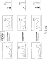
- Fig. 10 is a schematic diagram illustrating a method of calculating the control signal G, when normalization of each pixel value by using the maximum pixel value Lv in the image is performed before the noise removal processing or noise reduction processing by the neural network 60.
- the SNR-related data acquired by the SNR-related data acquisition function 40 correspond to the maximum pixel value Lv in the image.
- Lv1 maximum pixel values
- Lv3 maximum pixel values
- the magnitude (e.g., rms value of noise) of noise of an image at the time of imaging i.e., noise of the image before normalization
- the magnitude N of the normalized noise differs for each image, as shown in the right column of Fig. 10 (N2 ⁇ N1 ⁇ N3).
- the internal parameters of the respective nodes are adjusted in accordance with the control signal provided from the parameter adjustment function 50.
- Fig. 11A to Fig. 11C are schematic diagrams illustrating a case where the internal parameter adjusted in the step ST23 is the threshold value T of the Soft-Shrinkage function.
- the gain G i.e., magnitude of noise
- the width of the input at which the output becomes zero also increases, and the effect of removing or reducing noise is maintained, independent of the magnitude of the noise.
- the image inputted to the input I/F 11 is inputted to the neural network 60.
- the image inputted to the neural network 60 is processed in the neural network 60.
- the image processed in the neural network 60 is outputted from the output I/F 12.
- Fig. 12 is a schematic diagram illustrating the operation concept of the neural network 60 of the present embodiment in the image processing mode.
- the image processing system 100 of the present embodiment has a function of acquiring the SNR-related data from the input image IMin of the neural network 60 and adjusting the parameters of the neural network 60 on the basis of the acquired SNR-related data.
- Conventional neural networks have the problem that the effect of removing or reducing noise decreases when magnitude of noise included in the image used in the learning mode is different in magnitude of noise included in the image in the image processing mode after the training.
- the image processing system 100 has a function of adjusting the parameters of the neural network 60 depending on the magnitude of noise included in the image that is inputted in the image processing mode.
- the image processing system 100 even when magnitude of noise included in the image used in the learning mode is different in magnitude of noise included in the image inputted in the image processing mode after training, it is possible to maintain the effect of removing or reducing noise.
- the SNR-related data are not limited to the gain G used for normalizing an image with the maximum pixel value, as mentioned above. Hereinafter, some other examples of the SNR-related data will be described.
- the SNR-related data acquisition function 40 may acquire an F-value and/or an exposure time of the camera at the time of imaging as the SNR-related data from, e.g., supplementary information of the camera image. This is because the F value and the exposure time influence the number of photons made incident on the pixels of the image sensor and the shot noise decreases as the number of photons increases.
- the SNR-related data acquisition function 40 may acquire one or more combinations of parameters related to imaging conditions from the MRI apparatus as the SNR-related data.
- the parameters related to imaging conditions are, e.g., number of phase encoding steps Ny, number of frequency encoding steps Nx, voxel volume ( ⁇ x ⁇ y ⁇ z), bandwidth Bw, and number of times of integration Nex. This is because SNR of a medical image generated by an MRI apparatus is expressed by the following expression. SNR ⁇ ⁇ x ⁇ y ⁇ z N x N y N ex B w
- the SNR-related data acquisition function 40 may acquire at least one of tube voltage, tube current, irradiation time, object size, exposure dose, and/or the number of beams, from the CT apparatus as the SNR-related data. This is because these parameters correlate with SNR and noise amount of a medical image generated by a CT apparatus.
- the SNR-related data acquisition function 40 may acquire the magnitude of the received signal and/or the gain of the signal receiver as the SNR-related data.
- the processing performance may deteriorate when dynamic range of the signal changes.
- a signal value such as Lv for adjusting the threshold value T of the Soft-Shrinkage function
- the processing circuitry 10 is connected to an image sensor (e.g., a camera) configured to generate image data in which dynamic range of each pixel corresponds to 10 bit.
- the SNR-related data acquisition function 40 may acquire information on the dynamic range of the pixel value and multiply the control signal G by the ratio between the dynamic range at the time of imaging and the dynamic range at the time of training.
- the image processing system 100 may be configured such that the noise removal or noise reduction performance can be changed by user's adjustment.
- a user sets the denoising strength (i.e., parameter value that changes degree of noise removal or noise reduction) via the input device 23 of the image processing system 100.
- the SNR-related data acquisition function 40 or the parameter adjustment function 50 can change the noise removal or noise reduction performance of the neural network 60 by acquiring the denoising strength having been set by the user and multiplying the control signal G by the denoising strength.
- Fig. 4 illustrates the case where the control signal is inputted from the parameter adjustment function 50 to every node 80 in each of the intermediate layers 62
- the image processing system 100 is not necessarily limited to this configuration.
- the image processing system 100 may be configured such that the control signal is inputted only to some of the nodes 80.
- the image processing system 100 may be configured such that only the parameters of some of the nodes 80 are adjusted on the basis of the SNR-related data, while the parameters of the other nodes 80 are fixed to parameter values determined in the learning mode.
- the Soft-shrinkage function F SS (x, T) shown in Fig. 6A and expressed by the equation (5), or the Hard-Shrinkage function F HS (x, T) shown in Fig. 6B are exemplified as the activation functions used in the present embodiment, various activation functions other than these two functions can also be used for the neural network 60 of the present embodiment.
- a function using the tanh function expressed by the following equation (6) may be used as the activation function.
- f x T x ⁇ f clip x , T , ⁇ T
- f x T f ReLU f ReLU x ⁇ T ⁇ f ReLU f ReLU ⁇ x ⁇ T
- Fig. 13 is a block diagram illustrating a configuration of the image processing system 100 according to the second embodiment.
- the block diagram of Fig. 13 shows the configuration focusing on the operation in the image processing mode and in particular, the internal configuration of the neural network 60 related to the image processing mode.
- the input device 23, the memory 21, the display 22, and the parameter learning function 20 among all the components of the image processing system 100 shown in Fig. 1 are omitted in Fig. 13 , these components may be included in the image processing system 100 according to the second embodiment.
- the neural network 60 of the second embodiment includes a neural network 60a for residual estimation, a path 807 bypassing the neural network 60a, and a subtractor 806 for subtracting the output (residual) of the neural network 60a from the output of the path 807.
- the neural network 60a is a neural network generated by residual learning.
- the neural network 60a estimates only the residual obtained by removing the signal value from each pixel value of the input image. That is to say, the neural network 60a estimates only the noise component included in the input image. Then, the neural network 60a outputs only the estimated noise component to one end of the subtractor 806.
- the input image including noise is inputted to the other end of the subtractor 806 through the path 807.
- the noise estimated by the neural network 60a is subtracted from the input image.
- the subtractor 806, i.e., the neural network 60 outputs such an image that noise is removed from the input image or noise is reduced.
- the neural network 60 of the second embodiment is also configured such that the internal parameters of the neural network 60a can be adjusted for residual estimation on the basis of the input image or the SNR-related data acquired from the supplementary information of the input image.
- the internal parameters of the neural network 60a can be adjusted for residual estimation on the basis of the input image or the SNR-related data acquired from the supplementary information of the input image.
- Fig. 14 is a block diagram illustrating a configuration of the image processing system 100 according to the third embodiment.
- the block diagram of Fig. 14 also illustrates the configuration focusing on the operation in the image processing mode and in particular, the internal configuration of the neural network 60 related to the image processing mode, similarly to Fig. 13 .
- the neural network 60 of the third embodiment is configured such that the input to the neural network 60 is divided into two paths to be processed.
- One path is provided with at least one adaptive-type neural network 60b, and another path is provided with at least one fixed-type neural network 60c.
- the neural network 60 is further provided with an adder 808 for adding the respective outputs of the two neural networks 60b and 60c.
- the adaptive-type neural network 60b is configured to be able to adjust its internal parameters in the image processing mode on the basis of the SNR-related data acquired from the input image or the supplementary information of the input image.
- the internal parameters of the fixed-type neural network 60c are fixed to the values determined in the learning mode, even in the image processing mode.
- the output I/F 12 outputs such an image that noise is reduced or removed from the inputted image, by adding the image outputted from the neural network 60b to the image outputted from the neural network 60c.
- the internal parameters of the neural network 60b are adjusted on the basis of the SNR-related data.
- the internal parameters of the neural network 60b are adjusted on the basis of the SNR-related data.
- Fig. 15 is a block diagram illustrating a configuration of the image processing system 100 according to the fourth embodiment.
- the block diagram of Fig. 15 also illustrates the configuration focusing on the operation in the image processing mode, and in particular, the internal configuration of the neural network 60 related to the image processing mode, similarly to Fig. 13 .
- the input device 23, the memory 21, the display 22, and the parameter learning function 20 shown in Fig. 1 are omitted in Fig. 15 , these components may be included in the image processing system 100 according to the fourth embodiment.
- the neural network 60 of the fourth embodiment is configured to divide a frequency region of an input image into a high frequency region and a low frequency region to perform processing on signals of two (or plural) frequency bands.
- the neural network 60 of the fourth embodiment 60 includes a divider 809, at least one neural network 60d for high frequency, at least one neural network 60e for low frequency, and an image composer 810.
- the divider 809 converts the input image expressed in the real space region into data in the spatial frequency region by performing, e.g., two-dimensional Fourier transform on the input image. Further, the divider 809 divides the transformed data in the spatial frequency region into, e.g., high frequency band data and low frequency band data by applying, e.g., a high pass filter and/or a low pass filter.
- the neural network 60d for high frequency may be configured as an internal-parameter adaptive type. That is, the image processing system 100 is configured such that the internal parameters can be adjusted on the basis of the SNR-related data acquired from the input image or the supplementary information of the input image even after training.
- the low frequency band data are inputted to the neural network 60e for low frequency and subjected to image processing.
- the neural network 60e for low frequency may be configured as an internal-parameter fixed type. That is, the internal parameters determined in the learning mode are fixed in the image processing mode, and the input data are processed in this state.
- the image composer 810 composes the respective images outputted from the neural networks 60d and 60e so as to cause the output I/F 12 to output such an image that noise is reduced or removed from the inputted image.
- the internal parameters of the neural network 60d are adjusted on the basis of the SNR-related data.
- FIG. 16 is a block diagram showing a configuration example of the image processing system 100 according to the fifth embodiment.
- the image processing system 100 determines the amount of noise ⁇ m of the input image based on the SNR-related data acquired from the input image itself or from the additional information of the input image by the SNR-related data acquisition function. Further, the image processing system 100 selects, by the neural network selection function 500 and the selector 820, a neural network 60f whose internal parameters have been adjusted by ⁇ m closest to the determined amount of noise ⁇ . Using the selected neural network 60f, the image processing system 100 outputs an image in which noise is removed or reduced as compared with the input image.
- FIG. 17 is a block diagram showing a configuration example of an embodiment in which the image processing system 100 is adapted to a medical information processing system.
- the neural network has been described as an example of a machine learning model after training, but the embodiment is not limited to this.
- the model after training obtained by the machine learning is not limited to processing apparatuses in which one or more nodes imitating cells are connected by one or more edges imitating nerves, but may be a function having processing parameters.
- a model after training obtained by the machine learning may be a regression model such as a linear regression model or a support vector machine (SVM) model, or a tree model such as a decision tree model, a regression tree model, or a random forest model.
- the model after training includes a model updated by self-training.
- the term "input image” is used as a target to be input to the neural network, but this "input image” includes projection data acquired by the CT apparatus, or input data before reconstruction such as k-space data obtained by the MRI apparatus.
- FIG. 17 a model after training 600 having processing parameters 600a, 600b, and 600c is illustrated.
- the input I/F 11 acquires input data obtained by the medical image diagnostic apparatus.
- the input data index acquisition function 700 acquires an index value related to noise of input data or an index value indicating the property of the input data.
- the processing parameter 600b is a processing parameter corresponding to the acquired index value.
- the model after training processing function 710 controls the model after training 600 having the processing parameter 600b corresponding to the index value in the input data so as to process the input data.
- the processing circuitry or the computer constituting the image processing system 100 has been described as being one.
- the number of processing circuitries or computers constituting the image processing system 100 is not limited to one, and the above-described processing may be performed by using plural processing circuitries or plural computers.
Abstract
Description
- Embodiments described herein relate generally to an image processing system and a medical information processing system.
- In recent years, a method of using a neural network has been used in the field of various types of image processing and image recognition. The neural network is a processing device in which one or more nodes simulating cells are connected by one or more edges that simulate nerves.
- The neural network has biases and weighting coefficients, both of which are associated with respective edges, as its internal parameters. In addition, each node has an activation function, and the parameters of the activation function are also included in the internal parameters of the neural network.
- Machine learning is used for calculating the internal parameters of the neural network. For instance, in a neural network aimed at removing noise of an image, the internal parameters are generally calculated in the following manner.
- First, initial setting is manually performed on various conditions such as connection relationship between respective nodes, initial values of the biases and weighting coefficients associated with respective edges, and an initial value of the parameter of the activation function in each node.
- Next, an image without noise (i.e., a "ground truth") and a "training image" in which noise is artificially superimposed on the ground truth are prepared. The initial parameters of the neural network are sequentially updated in such a manner that the difference between the training image processed in the neural network and the ground truth becomes smaller. Such a series of processing flow is called "training".
- When difference, e.g., mean square error (MSE) of each pixel of respective images, between the ground truth and the image obtained by processing the training image in the neural network (i.e., the processed training image) becomes smaller than a predetermined value, the training will end. The respective values of the internal parameters of the neural network at the end of training are held as internal parameters calculated by training.
- When using the neural network after the training, a noise-superimposed image in which actual noise is superimposed is inputted to a neural network having internal parameters calculated by the training, and an image in which noise is removed or reduced is obtained at the output of the neural network.
- In the neural network, high noise removal performance or noise reduction performance is obtained, when the amount of superimposed noise in the noise-superimposed image to be used is as large as the amount of noise in the training image, which has been used in the training process. However, in the neural network, the noise removal performance or noise reduction performance may deteriorate when the amount of noise in the noise-superimposed image to be used is different from the amount of noise in the training image.
- In order to cope with this problem, an approach may be considered in which plural training images, that have noise amounts different from each other, are used when training the internal parameters in the neural network, instead of using training images having a noise amount of a single magnitude. However, in this approach, when assuming the noise amount is same between the leaning process and the using process, the noise removal or noise reduction performance may be reduced, compared with the noise removal or reduction performance obtained by using the training images that have a noise amount of a single magnitude.
- In the accompanying drawings:
-
Fig. 1 is a block diagram illustrating a configuration of an image processing system of the first embodiment; -
Fig. 2 is a schematic diagram illustrating an internal configuration of a neural network in which a configuration capable of adjusting internal parameters is omitted; -
Fig. 3 is a schematic diagram illustrating an internal configuration of a node in which a configuration capable of adjusting internal parameters is omitted; -
Fig. 4 is a schematic diagram illustrating connection relationship between (a) the neural network of the present embodiment having a configuration capable of adjusting internal parameters and (b) an SNR-related data acquisition function and a parameter adjustment function, both of which provides a control signal to the neural network; -
Fig. 5 is a block diagram illustrating an internal configuration of one node of the present embodiment; -
Fig. 6A is a graph illustrating the Soft-Shrinkage function FSS(x, T) as one case of an activation function used in the present embodiment; -
Fig. 6B is a graph illustrating the Hard-Shrinkage function FHS(x, T) as one case of an activation function used in the present embodiment; -
Fig. 7 is a flowchart illustrating an operation of a learning mode; -
Fig. 8 is a schematic diagram illustrating processing of a learning mode in which a ground truth and a training image are used; -
Fig. 9 is a flowchart illustrating processing of an image processing mode, after training performed by a neural network; -
Fig. 10 is a schematic diagram illustrating a normalization process using a maximum pixel value and a calculation method of a control signal; -
Fig. 11A to Fig. 11C are schematic diagrams illustrating a case where a threshold value T of the Soft-Shrinkage function as an activation function is adjusted by the control signal G; -
Fig. 12 is a schematic diagram illustrating an operation concept of a neural network according to the present embodiment in the image processing mode; -
Fig. 13 is a block diagram illustrating a configuration of the image processing system according to the second embodiment; -
Fig. 14 is a block diagram illustrating a configuration of the image processing system according to the third embodiment; and -
Fig. 15 is a block diagram illustrating a configuration of the image processing system according to the fourth embodiment. -
Fig. 16 is a block diagram illustrating a configuration of the image processing system according to the fifth embodiment. -
Fig. 17 is a block diagram illustrating a configuration of a medical information processing system to which the image processing system is adapted. - Hereinafter, respective embodiments of image processing systems will be described with reference to the accompanying drawings. In the embodiments described below, the same reference signs are given for identical components in terms of configuration and function, and duplicate description is omitted.
- In one embodiment, an image processing system includes a memory and processing circuitry. The memory is configured to store a predetermined program. The processing circuitry is configured, by executing the predetermined program, to perform processing on an input image by exploiting a neural network having an input layer, an output layer, and an intermediate layer provided between the input layer and the output layer, the input image being inputted to the input layer, and adjust an internal parameter based on data related to the input image, while performing the processing on the input image after training of the neural network, the internal parameter being at least one internal parameter of at least one node included in the intermediate layer, and the input parameter having been calculated by the training of the neural network.
-
Fig. 1 is a block diagram illustrating an overall configuration of animage processing system 100 according to the first embodiment. Theimage processing system 100 is constituted by, e.g., a computer system. - As shown in
Fig. 1 , theimage processing system 100 includesprocessing circuitry 10, an input I/F (interface) 11, an output I/F (interface) 12,, amemory 21, adisplay 22, and aninput device 23. - The
processing circuitry 10 is, e.g., a circuit equipped with a central processing unit (CPU) and/or a special-purpose or general-purpose processor. The processor implements various functions described below by executing programs stored in thememory 21. Theprocessing circuitry 10 may be configured as hardware such as a field programmable gate array (FPGA) or an application specific integrated circuit (ASIC). The various functions described below can also be implemented by such hardware. Additionally, theprocessing circuitry 10 can implement the various functions by combining hardware processing and software processing based on its processor and programs. - The
memory 21 is a recording medium including a read-only memory (ROM), a random access memory (RAM), and an external memory device such as a hard disk drive (HDD) or an optical disc device. Thememory 21 stores various programs executed by a processor of theprocessing circuitry 10 as well as various types of data and information. - The
input device 23 includes various devices for an operator to input various types of information and data, and is configured as, e.g., a mouse, a keyboard, a trackball, and/or a touch panel. - The
display 22 is a display device such as a liquid crystal display panel, a plasma display panel, and an organic EL panel. - The input I/
F 11 and the output I/F 12 are interfaces for inputting and outputting images, respectively. Each of the input I/F 11 and the output I/F 12 may include various devices and circuits such as a wired or wireless LAN, various communication interfaces including a USB, a network interface including the Internet and a public telephone line, and a drive circuit of various storage media including an optical disk and a magnetic disk. By using these devices and circuits, the input I/F 11 and the output I/F 12 can input and output image data, respectively. - As shown in
Fig. 1 , theprocessing circuitry 10 implements aparameter learning function 20, a neural-network processing function 30, an SNR-relateddata acquisition function 40, and aparameter adjustment function 50 by, e.g., executing various programs stored in thememory 21. - The
parameter learning function 20 determines respective values of internal parameters of theneural network 60 by machine learning (hereinafter, simply referred to as learning) with the use of a training image, as described below. - The neural-
network processing function 30 performs a predetermined processing on the input image inputted to theneural network 60 after training, by using theneural network 60. - The SNR-related
data acquisition function 40 acquires at least one of signal strength of the input image, magnitude of noise in the input image, signal-to-noise ratio (SNR) of the input image, gain used in normalization processing, data related to the signal-to-noise ratio, from the input image or supplementary information of the input image (hereinafter, the data acquired by the SNR-related data acquisition function are referred to as "SNR-related data"). Note that the SNR-related data are data related to the input image. - The
parameter adjustment function 50 adjusts the respective values of the internal parameters of theneural network 60 on the basis of the SNR-related data acquired by the SNR-relateddata acquisition function 40, when the neural-network processing function 30 performs the predetermined processing on the input image inputted to theneural network 60 after training. - As to the
parameter learning function 20, the neural-network processing function 30, the SNR-relateddata acquisition function 40, and theparameter adjustment function 50, their details will be described below. -
Fig. 2 is a schematic diagram illustrating an internal configuration of theneural network 60. Although the internal parameters are adjustable in theimage processing system 100 according to the first embodiment,Fig. 2 illustrates only the basic configuration for avoiding complication and omits the configuration portion that can adjust the internal parameters. - As shown in
Fig. 2 , theneural network 60 has a multilayer structure that includes aninput layer 61, anoutput layer 63, and at least oneintermediate layer 62 between theinput layer 61 and theoutput layer 63. - The
input layer 61 includesplural input terminals 70. Theimage processing system 100 of the present embodiment performs image processing such as noise reduction processing or noise removal processing by using theneural network 60. In this case, image data are inputted to theinput layer 61. Further, for instance, pixel signals constituting image data are inputted to therespective input terminals 70 of theinput layer 61. - The
output layer 63 also hasplural output terminals 90. In theimage processing system 100 of the present embodiment, the image data subjected to the image processing are outputted from theoutput layer 63. For instance, pixel signals of the image data subjected to the image processing are outputted to therespective output terminals 90 of theoutput layer 63. - Each of the
intermediate layers 62 includesplural nodes 80. Focusing on oneintermediate layer 62 between otherintermediate layers 62, the output signals of theplural nodes 80 of the immediately precedingintermediate layer 62 are inputted to eachnode 80 of the focusedintermediate layer 62, and an output signal of eachnode 80 of the focusedintermediate layer 62 is distributed toplural nodes 80 of the immediately subsequentintermediate layer 62. - When the
intermediate layer 62 is immediately subsequent to theinput layer 61, plural signals of the respectiveplural input terminals 70 are inputted to eachnode 80 of thisintermediate layer 62, and each of the plural signals are outputted to thenodes 80 of theintermediate layer 62 of the subsequent stage. - When the
intermediate layer 62 is immediately prior to theoutput layer 63, output signals of therespective nodes 80 of thisintermediate layer 62 are outputted to theoutput terminals 90 of theoutput layer 63 -
Fig. 3 is a schematic diagram illustrating an internal configuration of thenode 80. AlthoughFig. 3 illustrates anode 80 in theintermediate layer 62 that is immediately subsequent to theinput layer 61, other nodes in theintermediate layer 62 may have the same configuration. Plural signals are inputted to thenode 80 shown inFig. 3 . Respective input signals are subjected to weighting withweights 800 through themultipliers 801, and then summed up by anadder 802. Further, anadder 804 adds abias 803 to the output of the adder, and then, the output of theadder 804 is sent to theactivation function 805. When the output ofadder 804 is defined as "x", "x" is expressed by the following equation (1).
- In the equation (1), "wi" is the
weight 800, "si" is the input signal, "i" is the number of the input signal, and "b" is thebias 803. - By applying the
activation function 805 to "x" in the equation (1), the output of thenode 80 is determined. Various subdifferentiable functions, such as a clipping function expressed by the equation (2), a ReLU function expressed by the equation (3), or a tanh function expressed by the equation (4), have been conventionally used.


- In the present embodiment, for instance, the Soft-Shrinkage function expressed by the following equation (5) may be used as the
activation function 805. The Soft-Shrinkage function will be described below.
- In addition, the internal parameters of the conventional
neural network 60 are determined by learning performed in advance. Then, when exploiting theneural network 60, i.e., when using theneural network 60, the respective determined values of the internal parameters are used in a fixed state. - By contrast, in the present embodiment, the respective values of the internal parameters of the
neural network 60 can be adjusted on the basis of data related to the input image, when predetermined processing is performed after training, i.e., when theneural network 60 is exploited after training. -
Fig. 4 is a schematic diagram illustrating connection relationship between (a) theneural network 60 of the present embodiment configured to be able to adjust the internal parameters and (b) theparameter adjustment function 50 and the SNR-relateddata acquisition function 40 providing a control signal to theneural network 60. - The
parameter adjustment function 50 supplies the control signal to at least somenodes 80 of the intermediate layers 62. For instance, theparameter adjustment function 50 supplies a control signal to thenodes 80 of at least oneintermediate layer 62. As shown inFig. 4 , the control signal may be supplied from theparameter adjustment function 50 to eachnode 80 of the intermediate layers 62. -
Fig. 5 is a block diagram illustrating an internal configuration of onenode 80 of the present embodiment. Thenode 80 shown inFig. 5 is configured such that threshold T, which is the parameter of the activation function 805 (i.e., one of the internal parameters of the node 80), is adjusted with respect to theactivation function 805. -
Fig. 6A is a graph illustrating a Soft-shrinkage function FSS(x, T) as an example of theactivation function 805 in which the threshold T is used as a parameter. Similarly,Fig. 6B is a graph illustrating a Hard-Shrinkage function FHS(x, T) as an example of theactivation function 805 in which the threshold T is used as a parameter. Each of the Soft-Shrinkage function FSS(x, T) and the Hard-Shrinkage function FHS(x, T) is a function that outputs zero when an input value lies within a predetermined positive/negative threshold ±T around zero, and outputs a value proportional to an input value when an input value lies outside the range of the threshold ±T. - Note that, when the input is out of the range of the threshold ±T, the amplitude of the output of the Soft-Shrinkage function FSS(x, T) becomes smaller than the amplitude "x" of the input by the threshold T. Meanwhile, the amplitude of the output of the Hard-Shrinkage function FHS(x, T) has the same value as the amplitude "x" of the input, when the input is out of the range of the threshold ±T,
By using the Soft-Shrinkage function FSS(x, T) or the Hard-Shrinkage function FHS(x, T) as theactivation function 805, a signal with amplitude smaller than the threshold value T, i.e., a weak signal, which most likely be a noise, can be made zero at the output of the activation function. - As described above, the
neural network 60, which uses the Soft-Shrinkage function FSS(x, T) or the Hard-Shrinkage function FHS(x, T) as theactivation function 805, is a technology for reducing noise in an image and exerts a noise reduction effect when the threshold value T is set to an appropriate magnitude with respect to the noise level. - As shown in
Fig 5 , the threshold value T can be determined by, e.g., T=αG as the product of the coefficient α, which is the internal parameter, and the control signal G, which comes from the outside. For instance, the SNR-relateddata acquisition function 40 acquires data related to SNR or magnitude of noise of the input image (i.e., SNR-related data) from the input image (or from its supplementary information) inputted via the input I/F 11, and outputs the acquired SNR-related data to theparameter adjustment function 50. Further, theparameter adjustment function 50 determines magnitude of the control signal G on the basis of the SNR-related data and supplies the control signal G to eachnode 80. For instance, when the SNR-related data indicates that SNR of the input image is low or noise included in the input image is large, theparameter adjustment function 50 sets the control signal G to be a large value and supplies it to each of thenodes 80. - The
image processing system 100 of the present embodiment is a system that exploits theneural network 60. Thus, theimage processing system 100 has "a learning mode" for causing theneural network 60 to learn and "an image processing mode" for performing image processing by exploiting theneural network 60 after the training performed by theneural network 60. -
Fig. 7 is a flowchart illustrating an operation of the learning mode of theimage processing system 100, out of the above-described two operation modes. - First, in the step ST10, the control signal G from the outside to the
neural network 60 is set to a fixed value. The control signal G shown inFig. 5 is fixed to, e.g., G=1. - In the next step ST11, the respective values of the internal parameters of the
neural network 60 are set to initial values (i.e., default values). For instance, the respective values of the internal parameters such as the value of theweight 800 in eachnode 80, the value of thebias 803, and the value of the coefficient α shown inFig. 5 are set to the initial values. - In the next step ST12, a ground truth IM is set. The
image processing system 100 according to the present embodiment performs processing for removing or reducing noise included in an input image. Thus, an image with no noise or an image with a very high SNR is selected as the ground truth IM, and this ground truth IM is set as preparation for training in theneural network 60. - In the next step ST13, a training image obtained by adding artificial noise to the ground truth is generated, and similarly, this training image is set as preparations for training in the
neural network 60. The artificial noise is, e.g., Gaussian noise that is generated by calculation so as to have a standard deviation σ of a predetermined magnitude, and the training image is generated by adding this artificial noise to each pixel value of the ground truth. - In the next step ST14, the generated training image is inputted to the
neural network 60, and its processing result is obtained. - For instance, the pixel values of the respective pixels of the training image, to which noise is added, are inputted to the
respective input terminals 70 of theinput layer 61 of theneural network 60. These pixel values propagate eachnode 80 of theintermediate layers 62 of theneural network 60 from theinput layer 61 to theoutput layer 63 while changing their values by being subjected to weighted addition, bias addition, and activation function processing shown inFig. 5 , and then outputted to theoutput terminals 90 of theoutput layer 63 as the pixel values of the image processed by theneural network 60. - In next step ST15, an error (i.e., training error) between the processed image and the ground truth is calculated. Specifically, as the training error, it is possible to use the mean square error (MSE) and the sum of square errors, both of which can be obtained from each pixel of the processed image and each pixel of the ground truth.
- In the next step ST16, the parameters of the neural network are updated such that the training error becomes smaller by using the error back propagation algorithm. In particular, the algorithms stated in the following
Document 1 and Document 2 can be used for updating the parameters of the Shrinkage function. - [Document 1] Z. Wang et.al, "Deep Networks for Image Super Resolution with Sparse Prior," Proc. ICCV2015.
- [Document 2] X. Zhang, "Thresholding Neural Network for Adaptive Noise Reduction," IEEE Transactions on Neural Networks, vol.12, no. 3, 2001.
- In the next step ST17, by using the correct image that is an image having a high SNR prepared separately from the ground truth and a verification image obtained by adding noise to the correct image, the
parameter learning function 20 calculates an error (generalization error) between the correct image and an image obtained by processing the verification image, using theneural network 60. - In the next step ST18, it is determined whether the generalization error has reached the local minimum value or not, and the parameter updating is completed when the generalization error reaches the local minimum value. Conversely, when the generalization error does not reach the local minimum value, the processing returns to the step ST12 and the processing is repeated from the step ST12.
-
Fig. 8 is a schematic diagram illustrating the above-described processing. As shown in the upper part ofFig. 8 , the ground truth IMa having no noise or a very high SNR is set on the output side of theneural network 60. In addition, a training image obtained by adding artificial noise Na to this ground truth IMa is inputted to theneural network 60. Then, the internal parameters of theneural network 60 are determined in such a manner that the training image processed by theneural network 60 approaches the ground truth. The process of determining these internal parameters is a process called machine learning or simply learning. - Although the number of the ground truth(s) used for training may be one, the training effect can be improved by causing the
neural network 60 to learn by using plural similar different ground truth. For instance, as shown in the middle part and the bottom part ofFig. 8 , the training effect can be enhanced by training with plural images in which the combination of the ground truth 1Mb and the training image IMb+Nb, and/or the combination of the ground truth IMc and the training image IMc+Nc are used in addition to the combination of the ground truth IMa and the training image IMa+Na. - In the case of training with the use of plural ground truth, first, the steps ST12 to ST18 in the flowchart of
Fig. 7 are executed for selected one of the plural ground truth. In this case, when it is determined that the generalization error has not reached the local minimum value for this selected ground truth in the step ST18, the processing returns to the step ST12, in which the ground truth is replaced by a new ground truth (i.e., another of the plural ground truth) so that the processing from the steps ST13 to ST18 is executed for the replaced new ground truth. - When training of all the ground truth has been completed, the internal parameters of the
neural network 60 after the training are stored in thememory 21 in the step ST19. Alternatively or additionally, information regarding the structure of theneural network 60 may be stored in thememory 21. That is, assuming that the structure of theneural network 60 and the internal parameters are referred to as a machine learning model, in the step ST19, the entire machine learning model after training may be stored. - Each process of the above-described learning mode is performed by the
parameter learning function 20 inFig. 1 . -
Fig. 9 is a flowchart illustrating processing of the image processing mode of theimage processing system 100, i.e., an operation mode at the time of exploiting theneural network 60 after completion of training by theneural network 60. - In the first step ST20, an image is inputted to the
processing circuitry 10 via the input I/F 11. Specifically, an image is inputted to the SNR-relateddata acquisition function 40. The image to be inputted is an image to be subjected to noise removal processing or noise reduction processing with the use of theneural network 60. For instance, the input image is an image imaged by a medical image diagnostic apparatus such as an MRI (magnetic resonance imaging) apparatus, a CT (computerized tomography) apparatus, and an ultrasonic diagnostic apparatus. The SNR-related data are attached to this image. - In the next step ST21, the SNR-related
data acquisition function 40 acquires the SNR-related data from the input image. - In the next step ST22, the
parameter adjustment function 50 generates the control signal for each of thenodes 80 of theneural network 60 from the SNR-related data. - There are various specific methods to acquire the SNR-related data from an input image to generate the control signal.
-
Fig. 10 is a schematic diagram illustrating a method of calculating the control signal G, when normalization of each pixel value by using the maximum pixel value Lv in the image is performed before the noise removal processing or noise reduction processing by theneural network 60. - When such normalization processing is performed, the SNR-related data acquired by the SNR-related
data acquisition function 40 correspond to the maximum pixel value Lv in the image. For instance, as shown in the left column ofFig. 10 , it is assumed that processing targets are three types of images and the respective maximum pixel values Lv of these three types of images are Lv1, Lv2, and Lv3, which are different from each other (Lv2 > Lv1 > Lv3). In this case, in order to make the maximum pixel values after normalization to become Smax, each pixel of respective three images is needed to be multiplied by the respective gains of G1=Smax/Lv1, G2=Smax/Lv2, and G3=Smax/Lv3. - Usually, the magnitude (e.g., rms value of noise) of noise of an image at the time of imaging (i.e., noise of the image before normalization) is common between images. Thus, when normalization is performed with respect to the maximum pixel value Lv in the image, the magnitude N of the normalized noise differs for each image, as shown in the right column of
Fig. 10 (N2 < N1 < N3). By providing the gain G used for the normalization to theneural network 60 as the control signal, it is possible to provide theneural network 60 with data that have correlation with the magnitude of the noise of the processing target image. - Returning to
Fig. 9 , in the next step ST23, the internal parameters of the respective nodes are adjusted in accordance with the control signal provided from theparameter adjustment function 50. -
Fig. 11A to Fig. 11C are schematic diagrams illustrating a case where the internal parameter adjusted in the step ST23 is the threshold value T of the Soft-Shrinkage function. Specifically,Fig. 11A illustrates a case where theactivation function 805 is the Soft-Shrinkage function expressed by the equation (5) and the threshold T of the Soft-Shrinkage function is adjusted by the control signal G so as to become T1=αG1. Similarly,Fig. 11B and Fig. 11C illustrate cases where theactivation function 805 is the same Soft-Shrinkage function and the threshold T of the Soft-Shrinkage function is adjusted by the control signal G so as to become T2=AG2 and T3=αG3, respectively. - As the gain G (i.e., magnitude of noise) increases, the width of the input at which the output becomes zero also increases, and the effect of removing or reducing noise is maintained, independent of the magnitude of the noise.
- In the next step ST24, the image inputted to the input I/
F 11 is inputted to theneural network 60. - In the next step ST25, the image inputted to the
neural network 60 is processed in theneural network 60. - In the next step ST26, the image processed in the
neural network 60 is outputted from the output I/F 12. -
Fig. 12 is a schematic diagram illustrating the operation concept of theneural network 60 of the present embodiment in the image processing mode. Theimage processing system 100 of the present embodiment has a function of acquiring the SNR-related data from the input image IMin of theneural network 60 and adjusting the parameters of theneural network 60 on the basis of the acquired SNR-related data. - Conventional neural networks have the problem that the effect of removing or reducing noise decreases when magnitude of noise included in the image used in the learning mode is different in magnitude of noise included in the image in the image processing mode after the training.
- However, even after training of the
neural network 60, theimage processing system 100 according to the present embodiment has a function of adjusting the parameters of theneural network 60 depending on the magnitude of noise included in the image that is inputted in the image processing mode. As a result, even when magnitude of noise included in the image used in the learning mode is different in magnitude of noise included in the image inputted in the image processing mode after training, it is possible to maintain the effect of removing or reducing noise. - The SNR-related data are not limited to the gain G used for normalizing an image with the maximum pixel value, as mentioned above. Hereinafter, some other examples of the SNR-related data will be described.
- For instance, when the image to be processed is an image imaged by a camera, the SNR-related
data acquisition function 40 may acquire an F-value and/or an exposure time of the camera at the time of imaging as the SNR-related data from, e.g., supplementary information of the camera image. This is because the F value and the exposure time influence the number of photons made incident on the pixels of the image sensor and the shot noise decreases as the number of photons increases. - For instance, when the image to be processed is a medical image generated by an MRI apparatus, the SNR-related
data acquisition function 40 may acquire one or more combinations of parameters related to imaging conditions from the MRI apparatus as the SNR-related data. The parameters related to imaging conditions are, e.g., number of phase encoding steps Ny, number of frequency encoding steps Nx, voxel volume (ΔxΔyΔz), bandwidth Bw, and number of times of integration Nex. This is because SNR of a medical image generated by an MRI apparatus is expressed by the following expression.
- Further, for instance, when the image to be processed is a medical image generated by a CT apparatus, the SNR-related
data acquisition function 40 may acquire at least one of tube voltage, tube current, irradiation time, object size, exposure dose, and/or the number of beams, from the CT apparatus as the SNR-related data. This is because these parameters correlate with SNR and noise amount of a medical image generated by a CT apparatus. - In addition, when the image to be processed is a radar image, the SNR-related
data acquisition function 40 may acquire the magnitude of the received signal and/or the gain of the signal receiver as the SNR-related data. - Further, in the case of using a signal value such as Lv for adjusting the threshold value T of the Soft-Shrinkage function, there is a possibility that the processing performance may deteriorate when dynamic range of the signal changes. For instance, consider a case where training is completed by using data of an input image in which dynamic range of each pixel value corresponds to 8 bit, while the
processing circuitry 10 is connected to an image sensor (e.g., a camera) configured to generate image data in which dynamic range of each pixel corresponds to 10 bit. In this case, since magnitude of noise becomes relatively smaller as dynamic range of each pixel becomes larger, the value of the threshold value T becomes smaller and the noise removal performance consequently deteriorates as shown by the comparison betweenFig. 11B and Fig. 11C . In such a case, the SNR-relateddata acquisition function 40 may acquire information on the dynamic range of the pixel value and multiply the control signal G by the ratio between the dynamic range at the time of imaging and the dynamic range at the time of training. - Moreover, the
image processing system 100 may be configured such that the noise removal or noise reduction performance can be changed by user's adjustment. For instance, a user sets the denoising strength (i.e., parameter value that changes degree of noise removal or noise reduction) via theinput device 23 of theimage processing system 100. The SNR-relateddata acquisition function 40 or theparameter adjustment function 50 can change the noise removal or noise reduction performance of theneural network 60 by acquiring the denoising strength having been set by the user and multiplying the control signal G by the denoising strength. - Although
Fig. 4 illustrates the case where the control signal is inputted from theparameter adjustment function 50 to everynode 80 in each of theintermediate layers 62, theimage processing system 100 is not necessarily limited to this configuration. Theimage processing system 100 may be configured such that the control signal is inputted only to some of thenodes 80. Alternatively, theimage processing system 100 may be configured such that only the parameters of some of thenodes 80 are adjusted on the basis of the SNR-related data, while the parameters of theother nodes 80 are fixed to parameter values determined in the learning mode. - Although the Soft-shrinkage function FSS(x, T) shown in
Fig. 6A and expressed by the equation (5), or the Hard-Shrinkage function FHS(x, T) shown inFig. 6B are exemplified as the activation functions used in the present embodiment, various activation functions other than these two functions can also be used for theneural network 60 of the present embodiment. - For instance, a function using the tanh function expressed by the following equation (6) may be used as the activation function.

- Alternatively, a function using the clipping function fclip expressed by the following equation (7) may be used as the activation function.

- Further alternatively, a function using the ReLU function fReLU expressed by the following equation (8) may be used as the activation function.

- Hereinafter, a description will be given of embodiments of the
neural network 60 that has a configuration different from the configuration of the above-described first embodiment. -
Fig. 13 is a block diagram illustrating a configuration of theimage processing system 100 according to the second embodiment. The block diagram ofFig. 13 shows the configuration focusing on the operation in the image processing mode and in particular, the internal configuration of theneural network 60 related to the image processing mode. Although theinput device 23, thememory 21, thedisplay 22, and theparameter learning function 20 among all the components of theimage processing system 100 shown inFig. 1 are omitted inFig. 13 , these components may be included in theimage processing system 100 according to the second embodiment. - The
neural network 60 of the second embodiment includes aneural network 60a for residual estimation, apath 807 bypassing theneural network 60a, and asubtractor 806 for subtracting the output (residual) of theneural network 60a from the output of thepath 807. - The
neural network 60a is a neural network generated by residual learning. In this case, theneural network 60a estimates only the residual obtained by removing the signal value from each pixel value of the input image. That is to say, theneural network 60a estimates only the noise component included in the input image. Then, theneural network 60a outputs only the estimated noise component to one end of thesubtractor 806. - Meanwhile, the input image including noise is inputted to the other end of the
subtractor 806 through thepath 807. In thesubtractor 806, the noise estimated by theneural network 60a is subtracted from the input image. As a result, thesubtractor 806, i.e., theneural network 60 outputs such an image that noise is removed from the input image or noise is reduced. - The
neural network 60 of the second embodiment is also configured such that the internal parameters of theneural network 60a can be adjusted for residual estimation on the basis of the input image or the SNR-related data acquired from the supplementary information of the input image. Thus, even when magnitude of noise in the image used in the learning mode is different from that used in the image processing mode, deterioration of noise removal or noise reduction performance can be prevented. -
Fig. 14 is a block diagram illustrating a configuration of theimage processing system 100 according to the third embodiment. The block diagram ofFig. 14 also illustrates the configuration focusing on the operation in the image processing mode and in particular, the internal configuration of theneural network 60 related to the image processing mode, similarly toFig. 13 . - The
neural network 60 of the third embodiment is configured such that the input to theneural network 60 is divided into two paths to be processed. One path is provided with at least one adaptive-typeneural network 60b, and another path is provided with at least one fixed-typeneural network 60c. Theneural network 60 is further provided with anadder 808 for adding the respective outputs of the twoneural networks - In the
image processing system 100 according to the third embodiment, only the adaptive-typeneural network 60b is configured to be able to adjust its internal parameters in the image processing mode on the basis of the SNR-related data acquired from the input image or the supplementary information of the input image. In the meantime, the internal parameters of the fixed-typeneural network 60c are fixed to the values determined in the learning mode, even in the image processing mode. - Since noise is removed or reduced in the respective images outputted from the
neural network 60b and theneural network 60c, the output I/F 12 outputs such an image that noise is reduced or removed from the inputted image, by adding the image outputted from theneural network 60b to the image outputted from theneural network 60c. - Note that even in the third embodiment, the internal parameters of the
neural network 60b are adjusted on the basis of the SNR-related data. Thus, even when noise of the image used in the learning mode is different from that used in the image processing mode, deterioration of noise removal or noise reduction performance can be prevented. -
Fig. 15 is a block diagram illustrating a configuration of theimage processing system 100 according to the fourth embodiment. The block diagram ofFig. 15 also illustrates the configuration focusing on the operation in the image processing mode, and in particular, the internal configuration of theneural network 60 related to the image processing mode, similarly toFig. 13 . Although theinput device 23, thememory 21, thedisplay 22, and theparameter learning function 20 shown inFig. 1 are omitted inFig. 15 , these components may be included in theimage processing system 100 according to the fourth embodiment. - The
neural network 60 of the fourth embodiment is configured to divide a frequency region of an input image into a high frequency region and a low frequency region to perform processing on signals of two (or plural) frequency bands. For instance, theneural network 60 of thefourth embodiment 60 includes adivider 809, at least oneneural network 60d for high frequency, at least oneneural network 60e for low frequency, and animage composer 810. - The
divider 809 converts the input image expressed in the real space region into data in the spatial frequency region by performing, e.g., two-dimensional Fourier transform on the input image. Further, thedivider 809 divides the transformed data in the spatial frequency region into, e.g., high frequency band data and low frequency band data by applying, e.g., a high pass filter and/or a low pass filter. - Thereafter, the high frequency band data are inputted to the
neural network 60d for high frequency and subjected to image processing. Theneural network 60d for high frequency may be configured as an internal-parameter adaptive type. That is, theimage processing system 100 is configured such that the internal parameters can be adjusted on the basis of the SNR-related data acquired from the input image or the supplementary information of the input image even after training. - On the other hand, the low frequency band data are inputted to the
neural network 60e for low frequency and subjected to image processing. Theneural network 60e for low frequency may be configured as an internal-parameter fixed type. That is, the internal parameters determined in the learning mode are fixed in the image processing mode, and the input data are processed in this state. - Since noise is removed or reduced in the respective images outputted from the
neural networks image composer 810 composes the respective images outputted from theneural networks F 12 to output such an image that noise is reduced or removed from the inputted image. - Also in the fourth embodiment, the internal parameters of the
neural network 60d are adjusted on the basis of the SNR-related data. Thus, even when magnitude of noise used in the learning mode is different from that used in the image processing mode, deterioration of the noise removal or noise reduction performance can be prevented. -
FIG. 16 is a block diagram showing a configuration example of theimage processing system 100 according to the fifth embodiment. In the embodiments so far, examples in which the internal parameters of the neural network can be adjusted have been described, but the embodiments are not limited to these examples. For example, in the "learning mode", theimage processing system 100 generates neural networks according to the amount of noise using training images classified according to the amount of noise. That is, as shown inFIG. 16 , in the "learning mode", theimage processing system 100 generates a plurality ofneural networks 60f whose internal parameters have been adjusted according to the amount of noise σm (m = 1 to M). - In the meantime, in the "image processing mode", the
image processing system 100 determines the amount of noise σm of the input image based on the SNR-related data acquired from the input image itself or from the additional information of the input image by the SNR-related data acquisition function. Further, theimage processing system 100 selects, by the neuralnetwork selection function 500 and theselector 820, aneural network 60f whose internal parameters have been adjusted by σm closest to the determined amount of noise σ. Using the selectedneural network 60f, theimage processing system 100 outputs an image in which noise is removed or reduced as compared with the input image. -
FIG. 17 is a block diagram showing a configuration example of an embodiment in which theimage processing system 100 is adapted to a medical information processing system. In the embodiments so far, the neural network has been described as an example of a machine learning model after training, but the embodiment is not limited to this. The model after training obtained by the machine learning is not limited to processing apparatuses in which one or more nodes imitating cells are connected by one or more edges imitating nerves, but may be a function having processing parameters. For example, a model after training obtained by the machine learning may be a regression model such as a linear regression model or a support vector machine (SVM) model, or a tree model such as a decision tree model, a regression tree model, or a random forest model. Incidentally, the model after training includes a model updated by self-training. - In the embodiments so far, the term "input image" is used as a target to be input to the neural network, but this "input image" includes projection data acquired by the CT apparatus, or input data before reconstruction such as k-space data obtained by the MRI apparatus. In
FIG. 17 , a model after training 600 havingprocessing parameters F 11 acquires input data obtained by the medical image diagnostic apparatus. Further, the input dataindex acquisition function 700 acquires an index value related to noise of input data or an index value indicating the property of the input data. Theprocessing parameter 600b is a processing parameter corresponding to the acquired index value. The model aftertraining processing function 710 controls the model after training 600 having theprocessing parameter 600b corresponding to the index value in the input data so as to process the input data. - In the above-described embodiments, the processing circuitry or the computer constituting the
image processing system 100 has been described as being one. However, the number of processing circuitries or computers constituting theimage processing system 100 is not limited to one, and the above-described processing may be performed by using plural processing circuitries or plural computers. - According to at least one embodiment described above, even when the amount of noise superimposed on an image at the time of use is different from the amount of noise of the training image in the image processing system that uses the neural network, high noise removal or high noise reduction performance can be secured.
- While certain embodiments have been described, these embodiments have been presented by way of example only, and are not intended to limit the scope of the inventions. Indeed, the novel methods and systems described herein may be embodied in a variety of other forms; furthermore, various omissions, substitutions and changes in the form of the methods and systems described herein may be made without departing from the spirit of the inventions. The accompanying claims and their equivalents are intended to cover such forms or modifications as would fall within the scope and spirit of the inventions.
Claims (12)
- An image processing system comprising:a memory configured to store a predetermined program; andprocessing circuitry configured, by executing the predetermined program, toperform processing on an input image by exploiting a neural network having an input layer, an output layer, and an intermediate layer provided between the input layer and the output layer, the input image being inputted to the input layer, andadjust an internal parameter based on data related to the input image, while performing the processing on the input image after training of the neural network, the internal parameter being at least one internal parameter of at least one node included in the intermediate layer, and the input parameter having been calculated by the training of the neural network.
- The image processing system according to claim 1,
wherein the input image is an image that includes noise; and
the processing circuitry is configured to perform the processing on the input image in such a manner that the noise is reduced or removed from the input image. - The image processing system according to claim 1,
wherein the data related to the input image are SNR-related data that are related to magnitude of noise in the input image or signal-to-noise ratio of the input image. - The image processing system according to claim 1,
wherein the node has an activation function; and
the internal parameter is a parameter of the activation function. - The image processing system according to claim 4,
wherein the activation function is a function of removing such an input signal included in the input image that amplitude thereof is smaller than a threshold value; and
the internal parameter is the threshold value of the activation function. - The image processing system according to claim 4,
wherein the activation function is a function that outputs zero in a case of receiving an input value within a range including zero and outputs a value proportional to an input value in a case of receiving an input value outside the range. - The image processing system according to claim 1,
wherein the neural network includes a first neural network and a second neural network; and
the processing circuitry is configured to adjust an internal parameter of the first neural network based on the data related to the input image, and does not adjust an internal parameter of the second neural network. - The image processing system according to claim 1,
wherein the neural network comprises:a first neural network;a second neural network;a divider configured to divide an input image into a high-frequency component image and a low-frequency component image, output the high-frequency component image to the first neural network, and output the low-frequency component image to the second neural network; andan image composer configured to compose a first output image outputted from the first neural network and a second output image outputted from the second neural network, andthe processing circuitry is configured to adjust an internal parameter of the first neural network based on the data related to the input image, and does not adjust an internal parameter of the second neural network. - An image processing system comprising:a memory configured to store a predetermined program; andprocessing circuitry configured, by executing the predetermined program, togenerate an output image from an input image by exploiting a neural network in such a manner that noise of the output image is reduced, andadjust an internal parameter of the neural network according to an imaging condition of the input image.
- The image processing system according to claim 1,
wherein, the image processing system is configured as at least one computer. - A medical information processing system comprising:a memory configured to store a predetermined program; andprocessing circuitry configured, by executing the predetermined program, toacquire input data obtained by imaging an object with a medical image diagnostic apparatus,acquire an index value related to noise of the input data,process the input data based on a processing parameter,store a model after training which outputs a processed data in which the noise of the input data is reduced, andcontrol the model after training having the processing parameter corresponding to the index value in the input data so as to process the input data.
- A medical information processing system comprising:a memory configured to store a predetermined program; andprocessing circuitry configured, by executing the predetermined program, toacquire input data obtained by imaging an object with a medical image diagnostic apparatus,acquire an index value indicating a property of the input data,output, by a model after training, a processed data process in which the input data is processed based on a processing parameter, andcontrol the model after training having the processing parameter corresponding to the index value in the input data so as to process the input data.
Applications Claiming Priority (1)
| Application Number | Priority Date | Filing Date | Title |
|---|---|---|---|
| JP2017108934 | 2017-06-01 |
Publications (2)
| Publication Number | Publication Date |
|---|---|
| EP3410392A1 true EP3410392A1 (en) | 2018-12-05 |
| EP3410392B1 EP3410392B1 (en) | 2020-07-22 |
Family
ID=62683093
Family Applications (1)
| Application Number | Title | Priority Date | Filing Date |
|---|---|---|---|
| EP18175395.5A Active EP3410392B1 (en) | 2017-06-01 | 2018-05-31 | Image processing system and medical information processing system |
Country Status (3)
| Country | Link |
|---|---|
| US (2) | US11574170B2 (en) |
| EP (1) | EP3410392B1 (en) |
| JP (3) | JP7169094B2 (en) |
Cited By (9)
| Publication number | Priority date | Publication date | Assignee | Title |
|---|---|---|---|---|
| EP3734546A1 (en) * | 2019-05-02 | 2020-11-04 | Samsung Electronics Co., Ltd. | Electronic apparatus and image processing method thereof |
| KR20200127809A (en) * | 2019-05-02 | 2020-11-11 | 삼성전자주식회사 | Electronic apparatus and image processing method thereof |
| EP3828812A1 (en) * | 2019-11-29 | 2021-06-02 | Samsung Electronics Co., Ltd. | Electronic apparatus and control method thereof |
| GB2592725A (en) * | 2020-02-21 | 2021-09-08 | Adobe Inc | Controlling a neural network through intermediate latent spaces |
| US11415656B2 (en) | 2019-01-30 | 2022-08-16 | Canon Medical Systems Corporation | Medical information processing apparatus, magnetic resonance imaging apparatus, and medical information processing method |
| US11496682B2 (en) * | 2019-07-29 | 2022-11-08 | Canon Kabushiki Kaisha | Information processing apparatus that performs arithmetic processing of neural network, and image pickup apparatus, control method, and storage medium |
| US11669938B2 (en) | 2019-04-10 | 2023-06-06 | Canon Medical Systems Corporation | Medical information processing apparatus and medical information processing method |
| EP4242682A1 (en) * | 2022-03-07 | 2023-09-13 | FUJIFILM Healthcare Corporation | Magnetic resonance imaging apparatus, image processor, and image noise reduction method |
| EP4318015A1 (en) * | 2022-08-01 | 2024-02-07 | Koninklijke Philips N.V. | Mri denoising using specified noise profiles |
Families Citing this family (43)
| Publication number | Priority date | Publication date | Assignee | Title |
|---|---|---|---|---|
| KR102313773B1 (en) * | 2016-11-07 | 2021-10-19 | 삼성전자주식회사 | A method for input processing based on neural network learning algorithm and a device thereof |
| JP7068054B2 (en) | 2018-06-07 | 2022-05-16 | 株式会社東芝 | Distance measuring device and distance measuring method |
| JP7282487B2 (en) | 2018-06-07 | 2023-05-29 | キヤノンメディカルシステムズ株式会社 | Medical diagnostic imaging equipment |
| US10430708B1 (en) | 2018-08-17 | 2019-10-01 | Aivitae LLC | System and method for noise-based training of a prediction model |
| US10949951B2 (en) * | 2018-08-23 | 2021-03-16 | General Electric Company | Patient-specific deep learning image denoising methods and systems |
| EP3629240B1 (en) * | 2018-09-07 | 2023-08-23 | Panasonic Intellectual Property Corporation of America | Generative adversarial networks for local noise removal from an image |
| US10878311B2 (en) * | 2018-09-28 | 2020-12-29 | General Electric Company | Image quality-guided magnetic resonance imaging configuration |
| US11282172B2 (en) * | 2018-12-11 | 2022-03-22 | Google Llc | Guided restoration of video data using neural networks |
| JP7151788B2 (en) * | 2018-12-28 | 2022-10-12 | 日本電気株式会社 | Neural network learning device, method and program |
| CN111382642A (en) * | 2018-12-29 | 2020-07-07 | 北京市商汤科技开发有限公司 | Face attribute recognition method and device, electronic equipment and storage medium |
| JP7228386B2 (en) * | 2019-01-04 | 2023-02-24 | キヤノンメディカルシステムズ株式会社 | Medical image processing apparatus, magnetic resonance imaging apparatus, and medical image processing method |
| JP7273519B2 (en) * | 2019-01-17 | 2023-05-15 | キヤノンメディカルシステムズ株式会社 | Ultrasound diagnostic equipment and learning program |
| JP7302972B2 (en) * | 2019-01-17 | 2023-07-04 | キヤノンメディカルシステムズ株式会社 | Ultrasound diagnostic equipment and learning program |
| JP7246194B2 (en) * | 2019-01-28 | 2023-03-27 | キヤノンメディカルシステムズ株式会社 | MEDICAL IMAGE PROCESSING APPARATUS, MEDICAL IMAGE PROCESSING METHOD, AND PROGRAM |
| JP7297470B2 (en) * | 2019-03-05 | 2023-06-26 | キヤノン株式会社 | Image processing method, image processing apparatus, program, image processing system, and method for manufacturing trained model |
| JP7302988B2 (en) * | 2019-03-07 | 2023-07-04 | 富士フイルムヘルスケア株式会社 | Medical imaging device, medical image processing device, and medical image processing program |
| JP7301562B2 (en) * | 2019-03-14 | 2023-07-03 | キヤノンメディカルシステムズ株式会社 | Medical image processing device, learning data creation device and ultrasonic diagnostic device |
| JP2020162025A (en) * | 2019-03-27 | 2020-10-01 | キヤノン株式会社 | Image processing system, image processing method, and image processing device |
| WO2020219915A1 (en) * | 2019-04-24 | 2020-10-29 | University Of Virginia Patent Foundation | Denoising magnetic resonance images using unsupervised deep convolutional neural networks |
| JP7362297B2 (en) * | 2019-05-24 | 2023-10-17 | キヤノン株式会社 | Image processing device, image processing method, and program |
| CN112102423A (en) * | 2019-06-17 | 2020-12-18 | 通用电气精准医疗有限责任公司 | Medical imaging method and system |
| JP7094562B2 (en) * | 2019-07-05 | 2022-07-04 | イーグロース株式会社 | Bioimage acquisition device, transducer production device, bioimage production method, transducer production method, and program |
| WO2021020339A1 (en) * | 2019-07-26 | 2021-02-04 | 富士フイルム株式会社 | Learning image generation device, method, and program, and learning method, device, and program |
| JP7446736B2 (en) * | 2019-08-09 | 2024-03-11 | キヤノンメディカルシステムズ株式会社 | Medical data processing equipment and medical image diagnostic equipment |
| JP2021060847A (en) * | 2019-10-08 | 2021-04-15 | 株式会社ザクティ | Noise removal system |
| DE102019217220A1 (en) * | 2019-11-07 | 2021-05-12 | Siemens Healthcare Gmbh | Computer-implemented method for providing an output data set |
| JP7446797B2 (en) | 2019-12-03 | 2024-03-11 | キヤノン株式会社 | Image processing device, imaging device, image processing method and program |
| JPWO2021171394A1 (en) * | 2020-02-26 | 2021-09-02 | ||
| US11341616B2 (en) * | 2020-03-23 | 2022-05-24 | Ge Precision Healthcare | Methods and system for selective removal of streak artifacts and noise from images using deep neural networks |
| JPWO2021210612A1 (en) * | 2020-04-16 | 2021-10-21 | ||
| CN115427794A (en) * | 2020-04-16 | 2022-12-02 | 浜松光子学株式会社 | Radiological image processing method, learned model, radiological image processing module, radiological image processing program, radiological image processing system, and machine learning method |
| WO2021240589A1 (en) * | 2020-05-25 | 2021-12-02 | 三菱電機株式会社 | Learning device, inference device, program, learning method, and inference method |
| WO2021260822A1 (en) * | 2020-06-24 | 2021-12-30 | 三菱電機株式会社 | Learning device, inference device, program, learning method, and inference method |
| US11367167B2 (en) * | 2020-08-21 | 2022-06-21 | Apple Inc. | Neural network-based image processing with artifact compensation |
| WO2022163440A1 (en) * | 2021-01-29 | 2022-08-04 | 富士フイルム株式会社 | Information processing apparatus, imaging apparatus, information processing method, and program |
| US11699222B2 (en) * | 2021-02-19 | 2023-07-11 | Novatek Microelectronics Corp. | Image processing device and a method for image enhancement |
| JP2023008225A (en) * | 2021-07-05 | 2023-01-19 | 浜松ホトニクス株式会社 | Radiation image acquisition device, radiation image acquisition system and radiation image acquisition method |
| US20230099539A1 (en) * | 2021-09-30 | 2023-03-30 | Kwai Inc. | Methods and devices for image restoration using sub-band specific transform domain learning |
| WO2023067920A1 (en) * | 2021-10-19 | 2023-04-27 | LeapMind株式会社 | Image processing device, image processing system, image processing method, and program |
| JP2023077989A (en) * | 2021-11-25 | 2023-06-06 | キヤノン株式会社 | Radiation image processing apparatus, radiation image processing method, learning apparatus, learning data generation method, and program |
| JP2023077988A (en) * | 2021-11-25 | 2023-06-06 | キヤノン株式会社 | Radiation image processing apparatus, radiation image processing method, image processing apparatus, learning apparatus, learning data generation method, and program |
| JP2023172341A (en) | 2022-05-23 | 2023-12-06 | 日本電子株式会社 | Mass image processor and method for processing mass image |
| KR102650510B1 (en) * | 2022-10-28 | 2024-03-22 | 한국전자기술연구원 | Image noise reduction method and device |
Family Cites Families (8)
| Publication number | Priority date | Publication date | Assignee | Title |
|---|---|---|---|---|
| JP2006140952A (en) | 2004-11-15 | 2006-06-01 | Toa Corp | Image processor and image processing method |
| US8706662B2 (en) | 2011-07-21 | 2014-04-22 | Qualcomm Incorporated | Method and apparatus of controlling noise associated with synaptic inputs based on neuronal firing rate |
| US10043243B2 (en) * | 2016-01-22 | 2018-08-07 | Siemens Healthcare Gmbh | Deep unfolding algorithm for efficient image denoising under varying noise conditions |
| WO2017176384A2 (en) * | 2016-02-24 | 2017-10-12 | Sri International | Low precision neural networks using subband decomposition |
| US20180005111A1 (en) * | 2016-06-30 | 2018-01-04 | International Business Machines Corporation | Generalized Sigmoids and Activation Function Learning |
| US10242443B2 (en) * | 2016-11-23 | 2019-03-26 | General Electric Company | Deep learning medical systems and methods for medical procedures |
| US10133964B2 (en) * | 2017-03-28 | 2018-11-20 | Siemens Healthcare Gmbh | Magnetic resonance image reconstruction system and method |
| US10586310B2 (en) * | 2017-04-06 | 2020-03-10 | Pixar | Denoising Monte Carlo renderings using generative adversarial neural networks |
-
2018
- 2018-05-30 JP JP2018103025A patent/JP7169094B2/en active Active
- 2018-05-31 US US15/994,161 patent/US11574170B2/en active Active
- 2018-05-31 EP EP18175395.5A patent/EP3410392B1/en active Active
-
2022
- 2022-10-28 JP JP2022173383A patent/JP7427748B2/en active Active
- 2022-12-20 US US18/084,863 patent/US11886978B2/en active Active
-
2024
- 2024-01-23 JP JP2024008184A patent/JP2024028568A/en active Pending
Non-Patent Citations (6)
| Title |
|---|
| HOOMOD HAIDER KADIAM ET AL: "Fast image denoising based on modify CNN and noise estimation", 2017 ANNUAL CONFERENCE ON NEW TRENDS IN INFORMATION & COMMUNICATIONS TECHNOLOGY APPLICATIONS (NTICT), IEEE, 7 March 2017 (2017-03-07), pages 280 - 285, XP033119162, DOI: 10.1109/NTICT.2017.7976122 * |
| KENZO ISOGAWA ET AL: "Deep Shrinkage Convolutional Neural Network for Adaptive Noise Reduction", IEEE SIGNAL PROCESSING LETTERS., vol. 25, no. 2, February 2018 (2018-02-01), US, pages 224 - 228, XP055508221, ISSN: 1070-9908, DOI: 10.1109/LSP.2017.2782270 * |
| SZU-WEI FU ET AL: "SNR-Aware Convolutional Neural Network Modeling for Speech Enhancement", INTERSPEECH 2016, vol. 2016, 8 September 2016 (2016-09-08), pages 3768 - 3772, XP055427533, ISSN: 1990-9772, DOI: 10.21437/Interspeech.2016-211 * |
| X. ZHANG: "Thresholding Neural Network for Adaptive Noise Reduction", IEEE TRANSACTIONS ON NEURAL NETWORKS, vol. 12, no. 3, 2001, XP011039623, DOI: doi:10.1109/72.925559 |
| XIAO-PING ZHANG: "Thresholding Neural Network for Adaptive Noise Reduction", IEEE TRANSACTIONS ON NEURAL NETWORKS, IEEE SERVICE CENTER, PISCATAWAY, NJ, US, vol. 12, no. 3, May 2001 (2001-05-01), XP011039623, ISSN: 1045-9227, DOI: 10.1109/72.925559 * |
| Z. WANG: "Deep Networks for Image Super Resolution with Sparse Prior", PROC. ICCV2015 |
Cited By (22)
| Publication number | Priority date | Publication date | Assignee | Title |
|---|---|---|---|---|
| US11415656B2 (en) | 2019-01-30 | 2022-08-16 | Canon Medical Systems Corporation | Medical information processing apparatus, magnetic resonance imaging apparatus, and medical information processing method |
| US11815581B2 (en) | 2019-01-30 | 2023-11-14 | Canon Medical Systems Corporation | Medical information processing apparatus, magnetic resonance imaging apparatus, and medical information processing method |
| US11669938B2 (en) | 2019-04-10 | 2023-06-06 | Canon Medical Systems Corporation | Medical information processing apparatus and medical information processing method |
| WO2020222382A1 (en) * | 2019-05-02 | 2020-11-05 | Samsung Electronics Co., Ltd. | Electronic apparatus and image processing method thereof |
| KR20200127809A (en) * | 2019-05-02 | 2020-11-11 | 삼성전자주식회사 | Electronic apparatus and image processing method thereof |
| US11861809B2 (en) | 2019-05-02 | 2024-01-02 | Samsung Electronics Co., Ltd. | Electronic apparatus and image processing method thereof |
| EP3734546A1 (en) * | 2019-05-02 | 2020-11-04 | Samsung Electronics Co., Ltd. | Electronic apparatus and image processing method thereof |
| US11257189B2 (en) | 2019-05-02 | 2022-02-22 | Samsung Electronics Co., Ltd. | Electronic apparatus and image processing method thereof |
| US11659275B2 (en) | 2019-07-29 | 2023-05-23 | Canon Kabushiki Kaisha | Information processing apparatus that performs arithmetic processing of neural network, and image pickup apparatus, control method, and storage medium |
| US11496682B2 (en) * | 2019-07-29 | 2022-11-08 | Canon Kabushiki Kaisha | Information processing apparatus that performs arithmetic processing of neural network, and image pickup apparatus, control method, and storage medium |
| US11138717B2 (en) | 2019-11-29 | 2021-10-05 | Samsung Electronics Co., Ltd. | Electronic apparatus and control method thereof |
| US20220230296A1 (en) | 2019-11-29 | 2022-07-21 | Samsung Electronics Co., Ltd. | Electronic apparatus and control method thereof |
| US11315227B2 (en) | 2019-11-29 | 2022-04-26 | Samsung Electronics Co., Ltd. | Electronic apparatus and control method thereof |
| EP3961553A1 (en) * | 2019-11-29 | 2022-03-02 | Samsung Electronics Co., Ltd. | Electronic apparatus and control method thereof |
| US11763440B2 (en) | 2019-11-29 | 2023-09-19 | Samsung Electronics Co., Ltd. | Electronic apparatus and control method thereof |
| EP3828812A1 (en) * | 2019-11-29 | 2021-06-02 | Samsung Electronics Co., Ltd. | Electronic apparatus and control method thereof |
| US11657255B2 (en) | 2020-02-21 | 2023-05-23 | Adobe Inc. | Controlling a neural network through intermediate latent spaces |
| GB2592725A (en) * | 2020-02-21 | 2021-09-08 | Adobe Inc | Controlling a neural network through intermediate latent spaces |
| GB2592725B (en) * | 2020-02-21 | 2024-04-03 | Adobe Inc | Controlling a neural network through intermediate latent spaces |
| EP4242682A1 (en) * | 2022-03-07 | 2023-09-13 | FUJIFILM Healthcare Corporation | Magnetic resonance imaging apparatus, image processor, and image noise reduction method |
| EP4318015A1 (en) * | 2022-08-01 | 2024-02-07 | Koninklijke Philips N.V. | Mri denoising using specified noise profiles |
| WO2024028081A1 (en) * | 2022-08-01 | 2024-02-08 | Koninklijke Philips N.V. | Mri denoising using specified noise profiles |
Also Published As
| Publication number | Publication date |
|---|---|
| US11886978B2 (en) | 2024-01-30 |
| JP2024028568A (en) | 2024-03-04 |
| EP3410392B1 (en) | 2020-07-22 |
| JP7169094B2 (en) | 2022-11-10 |
| JP2023001217A (en) | 2023-01-04 |
| US20180349759A1 (en) | 2018-12-06 |
| US11574170B2 (en) | 2023-02-07 |
| JP2018206382A (en) | 2018-12-27 |
| US20230117621A1 (en) | 2023-04-20 |
| JP7427748B2 (en) | 2024-02-05 |
Similar Documents
| Publication | Publication Date | Title |
|---|---|---|
| EP3410392B1 (en) | Image processing system and medical information processing system | |
| RU2709437C1 (en) | Image processing method, an image processing device and a data medium | |
| Khan et al. | An adaptive dynamically weighted median filter for impulse noise removal | |
| JP7359850B2 (en) | Method and system for adaptive beamforming of ultrasound signals | |
| JP2018181187A (en) | Data analysis apparatus, data analysis method, and data analysis program | |
| CN110991636B (en) | Training method and device of generated countermeasure network, image enhancement method and device | |
| US10922587B2 (en) | Analyzing and correcting vulnerabilities in neural networks | |
| US11682110B2 (en) | Modularized adaptive processing neural network (MAP-NN) for low-dose CT | |
| US11536790B2 (en) | Medical information processing apparatus, medical information processing method, and storage medium | |
| JP7346270B2 (en) | Medical information processing device, medical information processing method, and program | |
| Zhou et al. | Nonlocal means filtering based speckle removal utilizing the maximum a posteriori estimation and the total variation image prior | |
| Wu et al. | Designing multi-task convolutional variational autoencoder for radio tomographic imaging | |
| CN111179235A (en) | Image detection model generation method and device, and application method and device | |
| Gerg et al. | Real-time, deep synthetic aperture sonar (sas) autofocus | |
| US20240127043A1 (en) | Image processing system and medical information processing system | |
| Li et al. | A robust neuro-fuzzy network approach to impulse noise filtering for color images | |
| Gunn et al. | Regularized training of intermediate layers for generative models for inverse problems | |
| CN115797186A (en) | Image restoration method and device, electronic equipment and storage medium | |
| Novikov-Borodin | Elimination of Systematic Distortions in the Signals of LTI Systems using Test Measurements | |
| US11965948B2 (en) | Medical information processing apparatus, medical information processing method, and storage medium | |
| Singh et al. | Noise-residue learning convolutional network model for magnetic resonance image enhancement | |
| CN111695624B (en) | Updating method, device, equipment and storage medium of data enhancement strategy | |
| EP4343680A1 (en) | De-noising data | |
| US20240005481A1 (en) | Apparatus, method, and non-transitory computer-readable storage medium for combining real-number-based and complex-number-based images | |
| US20230251338A1 (en) | Computer-Implemented Method for Determining Magnetic Resonance Images Showing Different Contrasts, Magnetic Resonance Device, Computer Program and Electronically Readable Storage Medium |
Legal Events
| Date | Code | Title | Description |
|---|---|---|---|
| PUAI | Public reference made under article 153(3) epc to a published international application that has entered the european phase |
Free format text: ORIGINAL CODE: 0009012 |
|
| STAA | Information on the status of an ep patent application or granted ep patent |
Free format text: STATUS: REQUEST FOR EXAMINATION WAS MADE |
|
| 17P | Request for examination filed |
Effective date: 20180531 |
|
| AK | Designated contracting states |
Kind code of ref document: A1 Designated state(s): AL AT BE BG CH CY CZ DE DK EE ES FI FR GB GR HR HU IE IS IT LI LT LU LV MC MK MT NL NO PL PT RO RS SE SI SK SM TR |
|
| AX | Request for extension of the european patent |
Extension state: BA ME |
|
| STAA | Information on the status of an ep patent application or granted ep patent |
Free format text: STATUS: EXAMINATION IS IN PROGRESS |
|
| 17Q | First examination report despatched |
Effective date: 20190719 |
|
| GRAP | Despatch of communication of intention to grant a patent |
Free format text: ORIGINAL CODE: EPIDOSNIGR1 |
|
| STAA | Information on the status of an ep patent application or granted ep patent |
Free format text: STATUS: GRANT OF PATENT IS INTENDED |
|
| INTG | Intention to grant announced |
Effective date: 20200206 |
|
| GRAS | Grant fee paid |
Free format text: ORIGINAL CODE: EPIDOSNIGR3 |
|
| GRAA | (expected) grant |
Free format text: ORIGINAL CODE: 0009210 |
|
| STAA | Information on the status of an ep patent application or granted ep patent |
Free format text: STATUS: THE PATENT HAS BEEN GRANTED |
|
| AK | Designated contracting states |
Kind code of ref document: B1 Designated state(s): AL AT BE BG CH CY CZ DE DK EE ES FI FR GB GR HR HU IE IS IT LI LT LU LV MC MK MT NL NO PL PT RO RS SE SI SK SM TR |
|
| REG | Reference to a national code |
Ref country code: GB Ref legal event code: FG4D |
|
| REG | Reference to a national code |
Ref country code: CH Ref legal event code: EP |
|
| REG | Reference to a national code |
Ref country code: DE Ref legal event code: R096 Ref document number: 602018006176 Country of ref document: DE |
|
| REG | Reference to a national code |
Ref country code: AT Ref legal event code: REF Ref document number: 1294121 Country of ref document: AT Kind code of ref document: T Effective date: 20200815 |
|
| REG | Reference to a national code |
Ref country code: IE Ref legal event code: FG4D |
|
| REG | Reference to a national code |
Ref country code: LT Ref legal event code: MG4D |
|
| REG | Reference to a national code |
Ref country code: AT Ref legal event code: MK05 Ref document number: 1294121 Country of ref document: AT Kind code of ref document: T Effective date: 20200722 |
|
| PG25 | Lapsed in a contracting state [announced via postgrant information from national office to epo] |
Ref country code: ES Free format text: LAPSE BECAUSE OF FAILURE TO SUBMIT A TRANSLATION OF THE DESCRIPTION OR TO PAY THE FEE WITHIN THE PRESCRIBED TIME-LIMIT Effective date: 20200722 Ref country code: LT Free format text: LAPSE BECAUSE OF FAILURE TO SUBMIT A TRANSLATION OF THE DESCRIPTION OR TO PAY THE FEE WITHIN THE PRESCRIBED TIME-LIMIT Effective date: 20200722 Ref country code: PT Free format text: LAPSE BECAUSE OF FAILURE TO SUBMIT A TRANSLATION OF THE DESCRIPTION OR TO PAY THE FEE WITHIN THE PRESCRIBED TIME-LIMIT Effective date: 20201123 Ref country code: HR Free format text: LAPSE BECAUSE OF FAILURE TO SUBMIT A TRANSLATION OF THE DESCRIPTION OR TO PAY THE FEE WITHIN THE PRESCRIBED TIME-LIMIT Effective date: 20200722 Ref country code: SE Free format text: LAPSE BECAUSE OF FAILURE TO SUBMIT A TRANSLATION OF THE DESCRIPTION OR TO PAY THE FEE WITHIN THE PRESCRIBED TIME-LIMIT Effective date: 20200722 Ref country code: BG Free format text: LAPSE BECAUSE OF FAILURE TO SUBMIT A TRANSLATION OF THE DESCRIPTION OR TO PAY THE FEE WITHIN THE PRESCRIBED TIME-LIMIT Effective date: 20201022 Ref country code: GR Free format text: LAPSE BECAUSE OF FAILURE TO SUBMIT A TRANSLATION OF THE DESCRIPTION OR TO PAY THE FEE WITHIN THE PRESCRIBED TIME-LIMIT Effective date: 20201023 Ref country code: NO Free format text: LAPSE BECAUSE OF FAILURE TO SUBMIT A TRANSLATION OF THE DESCRIPTION OR TO PAY THE FEE WITHIN THE PRESCRIBED TIME-LIMIT Effective date: 20201022 Ref country code: FI Free format text: LAPSE BECAUSE OF FAILURE TO SUBMIT A TRANSLATION OF THE DESCRIPTION OR TO PAY THE FEE WITHIN THE PRESCRIBED TIME-LIMIT Effective date: 20200722 Ref country code: AT Free format text: LAPSE BECAUSE OF FAILURE TO SUBMIT A TRANSLATION OF THE DESCRIPTION OR TO PAY THE FEE WITHIN THE PRESCRIBED TIME-LIMIT Effective date: 20200722 |
|
| PG25 | Lapsed in a contracting state [announced via postgrant information from national office to epo] |
Ref country code: RS Free format text: LAPSE BECAUSE OF FAILURE TO SUBMIT A TRANSLATION OF THE DESCRIPTION OR TO PAY THE FEE WITHIN THE PRESCRIBED TIME-LIMIT Effective date: 20200722 Ref country code: LV Free format text: LAPSE BECAUSE OF FAILURE TO SUBMIT A TRANSLATION OF THE DESCRIPTION OR TO PAY THE FEE WITHIN THE PRESCRIBED TIME-LIMIT Effective date: 20200722 Ref country code: PL Free format text: LAPSE BECAUSE OF FAILURE TO SUBMIT A TRANSLATION OF THE DESCRIPTION OR TO PAY THE FEE WITHIN THE PRESCRIBED TIME-LIMIT Effective date: 20200722 Ref country code: IS Free format text: LAPSE BECAUSE OF FAILURE TO SUBMIT A TRANSLATION OF THE DESCRIPTION OR TO PAY THE FEE WITHIN THE PRESCRIBED TIME-LIMIT Effective date: 20201122 |
|
| PG25 | Lapsed in a contracting state [announced via postgrant information from national office to epo] |
Ref country code: NL Free format text: LAPSE BECAUSE OF FAILURE TO SUBMIT A TRANSLATION OF THE DESCRIPTION OR TO PAY THE FEE WITHIN THE PRESCRIBED TIME-LIMIT Effective date: 20200722 |
|
| REG | Reference to a national code |
Ref country code: DE Ref legal event code: R097 Ref document number: 602018006176 Country of ref document: DE |
|
| PG25 | Lapsed in a contracting state [announced via postgrant information from national office to epo] |
Ref country code: CZ Free format text: LAPSE BECAUSE OF FAILURE TO SUBMIT A TRANSLATION OF THE DESCRIPTION OR TO PAY THE FEE WITHIN THE PRESCRIBED TIME-LIMIT Effective date: 20200722 Ref country code: DK Free format text: LAPSE BECAUSE OF FAILURE TO SUBMIT A TRANSLATION OF THE DESCRIPTION OR TO PAY THE FEE WITHIN THE PRESCRIBED TIME-LIMIT Effective date: 20200722 Ref country code: RO Free format text: LAPSE BECAUSE OF FAILURE TO SUBMIT A TRANSLATION OF THE DESCRIPTION OR TO PAY THE FEE WITHIN THE PRESCRIBED TIME-LIMIT Effective date: 20200722 Ref country code: EE Free format text: LAPSE BECAUSE OF FAILURE TO SUBMIT A TRANSLATION OF THE DESCRIPTION OR TO PAY THE FEE WITHIN THE PRESCRIBED TIME-LIMIT Effective date: 20200722 Ref country code: SM Free format text: LAPSE BECAUSE OF FAILURE TO SUBMIT A TRANSLATION OF THE DESCRIPTION OR TO PAY THE FEE WITHIN THE PRESCRIBED TIME-LIMIT Effective date: 20200722 Ref country code: IT Free format text: LAPSE BECAUSE OF FAILURE TO SUBMIT A TRANSLATION OF THE DESCRIPTION OR TO PAY THE FEE WITHIN THE PRESCRIBED TIME-LIMIT Effective date: 20200722 |
|
| PLBE | No opposition filed within time limit |
Free format text: ORIGINAL CODE: 0009261 |
|
| STAA | Information on the status of an ep patent application or granted ep patent |
Free format text: STATUS: NO OPPOSITION FILED WITHIN TIME LIMIT |
|
| PG25 | Lapsed in a contracting state [announced via postgrant information from national office to epo] |
Ref country code: AL Free format text: LAPSE BECAUSE OF FAILURE TO SUBMIT A TRANSLATION OF THE DESCRIPTION OR TO PAY THE FEE WITHIN THE PRESCRIBED TIME-LIMIT Effective date: 20200722 |
|
| 26N | No opposition filed |
Effective date: 20210423 |
|
| PG25 | Lapsed in a contracting state [announced via postgrant information from national office to epo] |
Ref country code: SK Free format text: LAPSE BECAUSE OF FAILURE TO SUBMIT A TRANSLATION OF THE DESCRIPTION OR TO PAY THE FEE WITHIN THE PRESCRIBED TIME-LIMIT Effective date: 20200722 |
|
| PG25 | Lapsed in a contracting state [announced via postgrant information from national office to epo] |
Ref country code: SI Free format text: LAPSE BECAUSE OF FAILURE TO SUBMIT A TRANSLATION OF THE DESCRIPTION OR TO PAY THE FEE WITHIN THE PRESCRIBED TIME-LIMIT Effective date: 20200722 |
|
| REG | Reference to a national code |
Ref country code: NL Ref legal event code: MP Effective date: 20200722 |
|
| REG | Reference to a national code |
Ref country code: CH Ref legal event code: PL |
|
| PG25 | Lapsed in a contracting state [announced via postgrant information from national office to epo] |
Ref country code: CH Free format text: LAPSE BECAUSE OF NON-PAYMENT OF DUE FEES Effective date: 20210531 Ref country code: MC Free format text: LAPSE BECAUSE OF FAILURE TO SUBMIT A TRANSLATION OF THE DESCRIPTION OR TO PAY THE FEE WITHIN THE PRESCRIBED TIME-LIMIT Effective date: 20200722 Ref country code: LI Free format text: LAPSE BECAUSE OF NON-PAYMENT OF DUE FEES Effective date: 20210531 Ref country code: LU Free format text: LAPSE BECAUSE OF NON-PAYMENT OF DUE FEES Effective date: 20210531 |
|
| REG | Reference to a national code |
Ref country code: BE Ref legal event code: MM Effective date: 20210531 |
|
| PG25 | Lapsed in a contracting state [announced via postgrant information from national office to epo] |
Ref country code: IE Free format text: LAPSE BECAUSE OF NON-PAYMENT OF DUE FEES Effective date: 20210531 |
|
| PG25 | Lapsed in a contracting state [announced via postgrant information from national office to epo] |
Ref country code: FR Free format text: LAPSE BECAUSE OF NON-PAYMENT OF DUE FEES Effective date: 20210531 |
|
| PG25 | Lapsed in a contracting state [announced via postgrant information from national office to epo] |
Ref country code: BE Free format text: LAPSE BECAUSE OF NON-PAYMENT OF DUE FEES Effective date: 20210531 |
|
| GBPC | Gb: european patent ceased through non-payment of renewal fee |
Effective date: 20220531 |
|
| PG25 | Lapsed in a contracting state [announced via postgrant information from national office to epo] |
Ref country code: GB Free format text: LAPSE BECAUSE OF NON-PAYMENT OF DUE FEES Effective date: 20220531 |
|
| PG25 | Lapsed in a contracting state [announced via postgrant information from national office to epo] |
Ref country code: CY Free format text: LAPSE BECAUSE OF FAILURE TO SUBMIT A TRANSLATION OF THE DESCRIPTION OR TO PAY THE FEE WITHIN THE PRESCRIBED TIME-LIMIT Effective date: 20200722 |
|
| PG25 | Lapsed in a contracting state [announced via postgrant information from national office to epo] |
Ref country code: HU Free format text: LAPSE BECAUSE OF FAILURE TO SUBMIT A TRANSLATION OF THE DESCRIPTION OR TO PAY THE FEE WITHIN THE PRESCRIBED TIME-LIMIT; INVALID AB INITIO Effective date: 20180531 |
|
| PGFP | Annual fee paid to national office [announced via postgrant information from national office to epo] |
Ref country code: DE Payment date: 20230404 Year of fee payment: 6 |