JP7359850B2 - Method and system for adaptive beamforming of ultrasound signals - Google Patents
Method and system for adaptive beamforming of ultrasound signals Download PDFInfo
- Publication number
- JP7359850B2 JP7359850B2 JP2021521781A JP2021521781A JP7359850B2 JP 7359850 B2 JP7359850 B2 JP 7359850B2 JP 2021521781 A JP2021521781 A JP 2021521781A JP 2021521781 A JP2021521781 A JP 2021521781A JP 7359850 B2 JP7359850 B2 JP 7359850B2
- Authority
- JP
- Japan
- Prior art keywords
- neural network
- signal
- artificial neural
- ultrasound
- output
- Prior art date
- Legal status (The legal status is an assumption and is not a legal conclusion. Google has not performed a legal analysis and makes no representation as to the accuracy of the status listed.)
- Active
Links
Images


Classifications
-
- G—PHYSICS
- G01—MEASURING; TESTING
- G01S—RADIO DIRECTION-FINDING; RADIO NAVIGATION; DETERMINING DISTANCE OR VELOCITY BY USE OF RADIO WAVES; LOCATING OR PRESENCE-DETECTING BY USE OF THE REFLECTION OR RERADIATION OF RADIO WAVES; ANALOGOUS ARRANGEMENTS USING OTHER WAVES
- G01S7/00—Details of systems according to groups G01S13/00, G01S15/00, G01S17/00
- G01S7/52—Details of systems according to groups G01S13/00, G01S15/00, G01S17/00 of systems according to group G01S15/00
- G01S7/52017—Details of systems according to groups G01S13/00, G01S15/00, G01S17/00 of systems according to group G01S15/00 particularly adapted to short-range imaging
- G01S7/52085—Details related to the ultrasound signal acquisition, e.g. scan sequences
-
- A—HUMAN NECESSITIES
- A61—MEDICAL OR VETERINARY SCIENCE; HYGIENE
- A61B—DIAGNOSIS; SURGERY; IDENTIFICATION
- A61B8/00—Diagnosis using ultrasonic, sonic or infrasonic waves
- A61B8/08—Detecting organic movements or changes, e.g. tumours, cysts, swellings
-
- G—PHYSICS
- G01—MEASURING; TESTING
- G01S—RADIO DIRECTION-FINDING; RADIO NAVIGATION; DETERMINING DISTANCE OR VELOCITY BY USE OF RADIO WAVES; LOCATING OR PRESENCE-DETECTING BY USE OF THE REFLECTION OR RERADIATION OF RADIO WAVES; ANALOGOUS ARRANGEMENTS USING OTHER WAVES
- G01S15/00—Systems using the reflection or reradiation of acoustic waves, e.g. sonar systems
- G01S15/88—Sonar systems specially adapted for specific applications
- G01S15/89—Sonar systems specially adapted for specific applications for mapping or imaging
- G01S15/8906—Short-range imaging systems; Acoustic microscope systems using pulse-echo techniques
- G01S15/8909—Short-range imaging systems; Acoustic microscope systems using pulse-echo techniques using a static transducer configuration
- G01S15/8915—Short-range imaging systems; Acoustic microscope systems using pulse-echo techniques using a static transducer configuration using a transducer array
-
- G—PHYSICS
- G01—MEASURING; TESTING
- G01S—RADIO DIRECTION-FINDING; RADIO NAVIGATION; DETERMINING DISTANCE OR VELOCITY BY USE OF RADIO WAVES; LOCATING OR PRESENCE-DETECTING BY USE OF THE REFLECTION OR RERADIATION OF RADIO WAVES; ANALOGOUS ARRANGEMENTS USING OTHER WAVES
- G01S7/00—Details of systems according to groups G01S13/00, G01S15/00, G01S17/00
- G01S7/52—Details of systems according to groups G01S13/00, G01S15/00, G01S17/00 of systems according to group G01S15/00
- G01S7/52017—Details of systems according to groups G01S13/00, G01S15/00, G01S17/00 of systems according to group G01S15/00 particularly adapted to short-range imaging
- G01S7/52046—Techniques for image enhancement involving transmitter or receiver
- G01S7/52047—Techniques for image enhancement involving transmitter or receiver for elimination of side lobes or of grating lobes; for increasing resolving power
-
- G—PHYSICS
- G06—COMPUTING; CALCULATING OR COUNTING
- G06N—COMPUTING ARRANGEMENTS BASED ON SPECIFIC COMPUTATIONAL MODELS
- G06N3/00—Computing arrangements based on biological models
- G06N3/02—Neural networks
- G06N3/04—Architecture, e.g. interconnection topology
- G06N3/044—Recurrent networks, e.g. Hopfield networks
-
- G—PHYSICS
- G06—COMPUTING; CALCULATING OR COUNTING
- G06N—COMPUTING ARRANGEMENTS BASED ON SPECIFIC COMPUTATIONAL MODELS
- G06N3/00—Computing arrangements based on biological models
- G06N3/02—Neural networks
- G06N3/04—Architecture, e.g. interconnection topology
- G06N3/045—Combinations of networks
-
- G—PHYSICS
- G06—COMPUTING; CALCULATING OR COUNTING
- G06N—COMPUTING ARRANGEMENTS BASED ON SPECIFIC COMPUTATIONAL MODELS
- G06N3/00—Computing arrangements based on biological models
- G06N3/02—Neural networks
- G06N3/04—Architecture, e.g. interconnection topology
- G06N3/048—Activation functions
-
- G—PHYSICS
- G06—COMPUTING; CALCULATING OR COUNTING
- G06N—COMPUTING ARRANGEMENTS BASED ON SPECIFIC COMPUTATIONAL MODELS
- G06N3/00—Computing arrangements based on biological models
- G06N3/02—Neural networks
- G06N3/08—Learning methods
-
- G—PHYSICS
- G06—COMPUTING; CALCULATING OR COUNTING
- G06N—COMPUTING ARRANGEMENTS BASED ON SPECIFIC COMPUTATIONAL MODELS
- G06N3/00—Computing arrangements based on biological models
- G06N3/02—Neural networks
- G06N3/08—Learning methods
- G06N3/082—Learning methods modifying the architecture, e.g. adding, deleting or silencing nodes or connections
-
- G—PHYSICS
- G06—COMPUTING; CALCULATING OR COUNTING
- G06N—COMPUTING ARRANGEMENTS BASED ON SPECIFIC COMPUTATIONAL MODELS
- G06N3/00—Computing arrangements based on biological models
- G06N3/02—Neural networks
- G06N3/08—Learning methods
- G06N3/084—Backpropagation, e.g. using gradient descent
-
- G—PHYSICS
- G10—MUSICAL INSTRUMENTS; ACOUSTICS
- G10K—SOUND-PRODUCING DEVICES; METHODS OR DEVICES FOR PROTECTING AGAINST, OR FOR DAMPING, NOISE OR OTHER ACOUSTIC WAVES IN GENERAL; ACOUSTICS NOT OTHERWISE PROVIDED FOR
- G10K11/00—Methods or devices for transmitting, conducting or directing sound in general; Methods or devices for protecting against, or for damping, noise or other acoustic waves in general
- G10K11/18—Methods or devices for transmitting, conducting or directing sound
- G10K11/26—Sound-focusing or directing, e.g. scanning
- G10K11/34—Sound-focusing or directing, e.g. scanning using electrical steering of transducer arrays, e.g. beam steering
Description
本発明は、超音波信号の適応ビームフォーミングのための方法、超音波信号の適応ビームフォーミングに有用な人工ニューラルネットワークを訓練する方法、並びに関連するコンピュータプログラム及びシステムに関する。 The present invention relates to methods for adaptive beamforming of ultrasound signals, methods for training artificial neural networks useful for adaptive beamforming of ultrasound signals, and related computer programs and systems.
K. E. Thomenius, "Evolution of ultrasound beamformers," 1996 IEEE Ultrason. Symp. Proc., vol. 2, pp. 1615-1622, 1996に記載されているように、伝統的な超音波画像方法は通常、遅延和(DAS)ビームフォーミングを使用するが、その理由はその複雑さが低く、再構成時間が速いからである。この方法は、受信チャネルに対して固定されたコンテント不変のアポダイゼーション重みを使用する。その再構成速度はリアルタイム撮像を可能にするが、DASビームフォーミングは、コンテント適応アレイアポディゼーションがないため、最適な画像コントラストと解像度を提供しない。例えば、軸外成分からの後方散乱は、十分に補償されない。この比較的劣った品質を改善するために、改善された画像は、多くの場合、取得時間の増加を犠牲にして、複数の取得を合成すること、及び/又は集束ビームを使用することによって得られる。 Traditional ultrasound imaging methods typically use delay-sum (DAS) beamforming is used because of its low complexity and fast reconfiguration time. This method uses content-invariant apodization weights that are fixed for the receive channel. Although its reconstruction speed allows real-time imaging, DAS beamforming does not provide optimal image contrast and resolution due to the lack of content-adaptive array apodization. For example, backscatter from off-axis components is not compensated well. To ameliorate this relatively poor quality, improved images are often obtained by combining multiple acquisitions and/or by using a focused beam, at the expense of increased acquisition time. It will be done.
適応ビームフォーミングアルゴリズムは、取得されたRF信号に基づいて、最適なコンテント適応アポダイゼーション重みを決定し、それらを受信チャネルに適用することによって、これを改善する。しかしながら、これらの方法は、計算的により要求が厳しく、従って、かなり長い再構成時間をもたらす。従って、現在知られている適応ビームフォーミングアルゴリズムは、リアルタイム超音波画像には適していない。 Adaptive beamforming algorithms improve this by determining optimal content-adaptive apodization weights based on the acquired RF signals and applying them to the receive channel. However, these methods are computationally more demanding and therefore result in considerably longer reconstruction times. Therefore, currently known adaptive beamforming algorithms are not suitable for real-time ultrasound images.
既知の適応ビームフォーミングアルゴリズムは、アポディゼーション後の受信信号の分散を最小にする一方で、所望の方向におけるユニティゲインを維持するようにアポディゼーション重みを連続的に最適化する最小分散(MV)ビームフォーマである。このプロセスは、典型的にはクラッタ画像につながる望ましくない方向からの干渉信号の電力を効果的に抑制する。MVビームフォーミングは、DASに比べて解像度とコントラストを大幅に向上させることができるが、n×nの空間共分散行列を反転する必要があり、その計算量はn3(nはチャンネル数)と非常に重いことが知られている。それゆえ、MVビームフォーミングは、リアルタイム画像には使用されない。 Known adaptive beamforming algorithms continuously optimize the apodization weights to minimize the dispersion of the received signal after apodization while maintaining unity gain in the desired direction. ) is a beamformer. This process effectively suppresses the power of interfering signals from undesired directions that typically lead to clutter images. MV beamforming can significantly improve resolution and contrast compared to DAS, but it requires inversion of the n×n spatial covariance matrix, and the computational complexity is n 3 (n is the number of channels). It is known to be very heavy. Therefore, MV beamforming is not used for real-time images.
MVビームフォーミング方法は、例えばI. K. Holfort, Adaptive Beamforming for Medical Ultrasound Imaging, PhD Thesis, Technical University of Denmark, Lyngby, November, 2009及びJ. F. Synnevag, A. Austeng, and S. Holm, "Benefits of minimum-variance beamforming in medical ultrasound imaging," IEEE Trans. Ultrason. Ferroelectr. Freq. Control, vol. 56, no. 9, pp. 1868-1879, 2009に記載されている。ビームフォーミングの一般的な原理は例えば、Chapter Two of the PhD Thesis by I.K. Holfort, Adaptive Beamforming for Medical Ultrasound Imagingに記載されており、これは参照により本明細書に組み込まれる。MVビームフォーミングでは、アポダイゼーション重みは、wHa=1として、min wHRwを解くことによって決定される。ここで、aは、ステアリングベクトルであり、Rは、入力アレイの共分散行列である。この最小化問題の解は、

である。共分散行列Rの反転は、特に大きな行列の場合、計算的に非常に高価であるため、リアルタイムの実行には適していない。
MV beamforming methods are described, for example, in IK Holfort, Adaptive Beamforming for Medical Ultrasound Imaging, PhD Thesis, Technical University of Denmark, Lyngby, November, 2009 and JF Synnevag, A. Austeng, and S. Holm, "Benefits of minimum-variance beamforming. in medical ultrasound imaging," IEEE Trans. Ultrason. Ferroelectr. Freq. Control, vol. 56, no. 9, pp. 1868-1879, 2009. The general principles of beamforming are described, for example, in Chapter Two of the PhD Thesis by IK Holfort, Adaptive Beamforming for Medical Ultrasound Imaging, which is incorporated herein by reference. For MV beamforming, the apodization weight is determined by solving for min w H Rw, with w H a=1. where a is the steering vector and R is the covariance matrix of the input array. The solution to this minimization problem is
It is. Inversion of the covariance matrix R is computationally very expensive, especially for large matrices, and is therefore not suitable for real-time implementation.
人工ニューラルネットワークは、画像形成及び特徴付けのための超音波イメージングのコンテキストにおいて提案されている(例えば、国際公開第2018/127498A1号公報を参照のこと)。本文献によれば、超音波イメージングシステムは、エコー信号を取得するように構成された超音波トランスデューサ、及び取得されたエコー信号を記憶するように構成されたチャネルメモリを有することができる。システムはまた、チャネルメモリに結合され、取得されたエコー信号又はビームフォーミングされた信号のうちの1つ又は複数のサンプルを受信し、取得されたエコー信号のうちの1つ又は複数のサンプルに基づいて撮像データを提供するように構成されたニューラルネットワークを有する。ニューラルネットワークは、イメージングデータを生成するか、又は組織情報を抽出するように訓練される。 Artificial neural networks have been proposed in the context of ultrasound imaging for image formation and characterization (see, for example, WO 2018/127498A1). According to this document, an ultrasound imaging system can have an ultrasound transducer configured to acquire echo signals and a channel memory configured to store the acquired echo signals. The system is also coupled to the channel memory and receives one or more samples of the acquired echo signal or the beamformed signal, and is configured to and a neural network configured to provide imaging data. Neural networks are trained to generate imaging data or extract tissue information.
Adam Luchies and Brett Byram, "Suppressing off-axis scattering using deep neural networks", Proceedings of SPIE 10580, Medical Imaging 2018: Ultrasonic Imaging and Tomography, 105800G, March 6, 2018によれば、超音波トランスデューサ素子から取得されたRF信号(チャネルデータとも呼ばれる)は、短時間フーリエ変換され、深層ニューラルネットワークへの入力として使用され、従って、深層ニューラルネットワークは、周波数ドメインで演算を行う。出力は入力と同じ構造を有し、逆短時間フーリエ変換が、処理されたデータを時間ドメインに戻すように変換し、処理されたチャネルデータを生成するためにするために使用され、処理されたデータは、チャネルにわたって合計される。 obtained from ultrasound transducer elements, according to Adam Luchies and Brett Byram, "Suppressing off-axis scattering using deep neural networks", Proceedings of SPIE 10580, Medical Imaging 2018: Ultrasonic Imaging and Tomography, 105800G, March 6, 2018. The RF signal (also called channel data) is short-time Fourier transformed and used as an input to a deep neural network, which thus performs operations in the frequency domain. The output has the same structure as the input and an inverse short-time Fourier transform is used to transform the processed data back to the time domain and generate the processed channel data. Data is summed across channels.
本発明の目的は、既知のコンテント適応ビームフォーミング方法と比較して、高い画質を提供すると同時に、計算コストを低減した適応ビームフォーミング方法を提供することである。特に、本発明の目的は、リアルタイム超音波画像に使用できる程度に計算時間を短縮しつつ、MVビームフォーミングなどの従来の適応ビームフォーミングアルゴリズムと同等の高い画像品質を提供することができる解決策を提供することである。 The aim of the invention is to provide an adaptive beamforming method that provides high image quality and at the same time reduces computational cost compared to known content adaptive beamforming methods. In particular, the aim of the present invention is to develop a solution that is able to reduce the computation time to the extent that it can be used for real-time ultrasound images, while still providing high image quality comparable to conventional adaptive beamforming algorithms such as MV beamforming. It is to provide.
これらの目的は、請求項1に記載の超音波信号の適応ビームフォーミングのための方法、請求項13に記載の訓練済み人工ニューラルネットワークを提供する方法、請求項14に記載のコンピュータプログラム、及び請求項15に記載のシステムによって満たされるか、又は超えられる。請求項に記載の方法に関連して本明細書で説明される任意の特徴、利点、又は代替の実施形態は、他の請求項のカテゴリ、特に請求項に記載のシステム、コンピュータプログラム、及び超音波画像デバイスにも適用可能である。特に、訓練済みニューラルネットワークは、請求項に記載された訓練方法によって適応されることができる。更に、人工ニューラルネットワークへの入力データは、入力トレーニングデータの有利な特徴及び実施形態を含むことができ、逆もまた同様である。更に、訓練済みニューラルネットワークの出力(コンテント適応アポダイゼーション重み)は、出力訓練データの有利な特徴及び実施形態を含むことができ、その逆も同様である。
These objects include a method for adaptive beamforming of ultrasound signals according to claim 1, a method for providing a trained artificial neural network according to claim 13, a computer program product according to
第1の態様によれば、本発明は超音波信号の適応ビームフォーミングのための方法を提供し、この方法は、(a)超音波送信に応答して複数の超音波トランスデューサ素子によって取得されたRF信号を受信するステップと、(b)訓練済み人工ニューラルネットワークをRF信号に適用することによってRF信号をビームフォーミングするためのコンテント適応アポダイゼーション重みを決定するステップとを含む。 According to a first aspect, the invention provides a method for adaptive beamforming of an ultrasound signal, the method comprising: (a) ultrasound signals acquired by a plurality of ultrasound transducer elements in response to ultrasound transmissions; (b) determining content-adaptive apodization weights for beamforming the RF signal by applying a trained artificial neural network to the RF signal.
従って、本発明の方法は、MVビームフォーミングのような今日の計算的に高価な方法の代替として人工ニューラルネットワーク(NN)を適用することによって、コンテント適応形式で最適な、又は最適に近いアポダイゼーション重みを得ることができる。この文脈における「コンテント適応(Content-adaptive)」は、アポダイゼーション重みが、取得されたRF信号に依存すること、すなわち、それらが信号のコンテントに適応されることを意味する。超音波画像の場合、それらは、イメージングされた視野に適応される。先行技術とは対照的に、NNの出力は、RF信号(チャネルデータ)又はビームフォーミングされた画像の形ではなく、出力は、各チャネルごとのアポディゼーション重みであり、よって、例えば乗算及び加算によって、通常の方法でビームフォーミングされた出力信号を生成するためにRF信号に適用されることができる。従って、NNへの入力はRF信号であり、次いで、これらの同じ信号が、NNの出力、すなわちアポディゼーション重みと乗算され、続いて、加算されて、ビームフォーミングされた出力信号を生成することができる。 Therefore, the method of the present invention provides optimal or near-optimal apodization weights in a content-adaptive manner by applying artificial neural networks (NNs) as an alternative to today's computationally expensive methods such as MV beamforming. can be obtained. "Content-adaptive" in this context means that the apodization weights depend on the acquired RF signal, ie they are adapted to the content of the signal. In the case of ultrasound images, they are adapted to the imaged field of view. In contrast to the prior art, the output of the NN is not in the form of RF signals (channel data) or beamformed images, the output is apodization weights for each channel, thus e.g. can be applied to the RF signal to generate a beamformed output signal in a conventional manner. Therefore, the inputs to the NN are RF signals, and these same signals are then multiplied with the output of the NN, i.e. the apodization weights, and subsequently summed to produce the beamformed output signal. I can do it.
完全なコンテント適応ビームフォーミング又は画像再構成プロセスは、1)飛行時間補正、2)アポディゼーション重みの適応(及び適用)、3)エンベロープ検出の3ステップに分けられる。本発明の方法は、適応アポダイゼーション重みの計算に焦点を当てており、これは、上述の3つのステップのうち計算的に最も高価なものである。 The complete content-adaptive beamforming or image reconstruction process is divided into three steps: 1) time-of-flight correction, 2) adaptation (and application) of apodization weights, and 3) envelope detection. Our method focuses on calculating adaptive apodization weights, which is the computationally most expensive of the three steps mentioned above.
NNへの入力は、人間又は動物の身体の部分などの媒体への超音波送信に応答して複数の超音波トランスデューサ素子によって取得される無線周波数(RF)信号である。取得されたRF信号は、振幅と位相の両方を持つ。従って、NNへの入力として使用されるRF信号は、実数であっても複素表現であってもよい。超音波イメージングでは、超音波送信によって撮像される領域は、視野と呼ばれる。複数の超音波トランスデューサ素子は、アレイトランスデューサ、例えば、線形トランスデューサ、又は、フェーズドアレイの複数又はすべての素子でありうる。いくつかの実施形態では、アポディゼーション重みは、アレイ内のトランスデューサ素子から取得されたすべてのRF信号について計算されるが、アレイ内のトランスデューサ素子のサブセットのみが、任意の所与の時点にRF信号を受信するイメージング方法もある。 The input to the NN is a radio frequency (RF) signal acquired by a plurality of ultrasound transducer elements in response to ultrasound transmission into a medium, such as a human or animal body part. The acquired RF signal has both amplitude and phase. Therefore, the RF signals used as inputs to the NN may be real or complex representations. In ultrasound imaging, the area imaged by ultrasound transmission is called the field of view. The plurality of ultrasound transducer elements can be an array transducer, eg, a linear transducer, or several or all elements of a phased array. In some embodiments, the apodization weights are calculated for all RF signals acquired from transducer elements in the array, but only a subset of the transducer elements in the array have RF There are also imaging methods that receive signals.
有用な実施形態では、NNへの入力が時間アラインされたRF信号、すなわち、飛行時間補正後の時間シフトRF信号又はRF信号であり、ここで、飛行時間補正において適用される遅延は、トランスデューサの幾何学的形状に対して相対的である。このような時間補正は、DASビームフォーミングと同様に行うことができる。好適には、この方法は、時間ドメインにおいて動作し、すなわち時間ドメインの信号に対して動作する。有用な実施形態に従って、NNのための入力を形成することができる時間アラインされたRF信号を生成するために、ピクセルごとの飛行時間補正が、受信されたRF信号(生のRF信号)に適用される。これにより、サイズNのデータアレイが得られ、ここで、Nは、寄与するトランスデューサ素子の数に対応する。従って、本方法は時間アラインされた信号を生成するために、信号に対して飛行時間補正を実行するステップを更に有することができる。 In useful embodiments, the input to the NN is a time-aligned RF signal, i.e., a time-shifted RF signal or RF signal after time-of-flight correction, where the delay applied in the time-of-flight correction is Relative to the geometry. Such time correction can be performed similarly to DAS beamforming. Preferably, the method operates in the time domain, ie on time domain signals. In accordance with useful embodiments, a pixel-by-pixel time-of-flight correction is applied to the received RF signal (raw RF signal) to generate a time-aligned RF signal that can form an input for the NN. be done. This results in a data array of size N, where N corresponds to the number of contributing transducer elements. Accordingly, the method may further include performing time-of-flight correction on the signal to produce a time-aligned signal.
チャネルデータとも呼ばれるRF信号は、「ニューラルネットワーク(neural network)」又はNNとも呼ばれる訓練済み人工ニューラルネットワークに供給される。人工ニューラルネットワーク(NN)は、ノードとも呼ばれる接続された人工ニューロンの集合に基づいており、各接続(エッジとも呼ばれる)は、1つのノードから別のノードに信号を送信することができる。信号を受信する各人工ニューロンは、信号を処理し、それに接続された更なる人工ニューロンに処理した信号を転送することができる。有用な実施形態では、本発明のNNの人工ニューロンが層状に配置される。入力信号(タイムアラインRF信号など)は、入力層とも呼ばれる最初のレイヤから最後のレイヤである出力層まで伝わる。有用な実施形態では、NNは、フィードフォワードネットワークであるが、それはまた、その内部状態を記憶し、それを一連の関連する入力の処理に使用することができるように、反復ニューラルネットワークの一部であってもよく、又は反復ニューラルネットワークであってもよい。有用な実施形態では、NNが機械学習技術、特に深層学習に基づいて、例えばバックプロパゲーションによって訓練される。使用されるトレーニングデータは、トレーニングターゲットとしてのMVビームフォーマのような高品質適応ビームフォーミングアルゴリズムの出力、及び入力トレーニングデータとしての関連する時間アラインされたRF信号でありうる。有用な実施形態では、本発明が、ニューラルネットワークを用いて計算要求の厳しい計算を行いながら、適応型ビームフォーマの構造を取り入れて設計されたNNアーキテクチャに対するモデルベースのアプローチを使用する。 The RF signal, also called channel data, is fed into a trained artificial neural network, also called a "neural network" or NN. Artificial neural networks (NNs) are based on a collection of connected artificial neurons, also called nodes, where each connection (also called an edge) can transmit a signal from one node to another. Each artificial neuron that receives a signal can process the signal and forward the processed signal to further artificial neurons connected to it. In a useful embodiment, the artificial neurons of the NN of the invention are arranged in layers. An input signal (such as a time-aligned RF signal) travels from the first layer, also called the input layer, to the last layer, the output layer. In a useful embodiment, the NN is a feedforward network, but it is also part of a recurrent neural network so that it remembers its internal state and can use it to process a series of related inputs. or a recurrent neural network. In a useful embodiment, the NN is trained based on machine learning techniques, in particular deep learning, for example by backpropagation. The training data used may be the output of a high quality adaptive beamforming algorithm, such as a MV beamformer, as the training target and the associated time-aligned RF signals as the input training data. In a useful embodiment, the present invention uses a model-based approach to NN architectures designed incorporating adaptive beamformer structures while performing computationally demanding calculations using neural networks.
本発明による訓練済み人工ニューラルネットワークは、ソフトウェアプログラムの形態で提供されてもよいが、ハードウェアとして実現されてもよい。更に、訓練済みのNNは、訓練済みニューラルネットワークと全く同じように必ずしも構造化されていない訓練された関数の形成で提供されることができ、例えば、特定の接続/エッジが重み0を有する場合、訓練後、訓練済み人工NNに基づく訓練済み関数を提供する際、そのような接続は省略されることができる。 A trained artificial neural network according to the invention may be provided in the form of a software program, but may also be implemented as hardware. Furthermore, a trained NN can be provided in the formation of trained functions that are not necessarily structured just like a trained neural network, e.g. if a particular connection/edge has a weight of 0. , after training, such connections can be omitted when providing a trained function based on a trained artificial NN.
訓練後、本発明のNNを使用すると、MVビームフォーミングの結果を上回るとまではいかないまでも、近似する高品質の画像が、わずかな計算時間で得られることがわかった。今日の実験では、その時間ゲインはおよそ500分の1になる。従って、本発明は、MVビームフォーマなどの既知の適応型ビームフォーミングアルゴリズムと同等の品質を、数分の1の計算コストで実現する、極めて高品質な適応型ビームフォーミング手法を提供する。そのため、本発明の方法では、超音波画像の品質をリアルタイムに向上させることができる。従って、本発明は、従来のハードウェアやGPUアクセラレーションを用いて、適応型ビームフォーミング技術に匹敵する画質を、高速に提供する。 After training, we have found that using our NN, high quality images that approximate, if not surpass, the results of MV beamforming can be obtained in a fraction of the computational time. In today's experiment, that time gain is approximately 1/500. Therefore, the present invention provides an extremely high quality adaptive beamforming technique that achieves the same quality as known adaptive beamforming algorithms such as the MV beamformer, but at a fraction of the computational cost. Therefore, with the method of the present invention, the quality of ultrasound images can be improved in real time. Therefore, the present invention uses conventional hardware and GPU acceleration to provide image quality comparable to adaptive beamforming techniques at high speed.
有用な実施形態によれば、人工ニューラルネットワークの入力ノードの数及び人工ニューラルネットワークの出力ノードの数は、寄与するRF信号の数に対応し、ここで、「寄与する」とは、寄与するRF信号が例えば、特定のビームフォーミングされた出力信号、例えば、特定のビームフォーミングされたピクセルにそれぞれ寄与することを意味する。従って、入力ノードの数Nは受信超音波トランスデューサ素子の数に対応し、受信超音波トランスデューサ素子は、トランスデューサアレイ内のトランスデューサ素子のすべて、又はそのサブセットとすることができる。好適には、各出力ノードが、1つの特定の入力ノードに供給される1つのRF信号に対するコンテント適応アポダイゼーション重みを供給する。従って、ほとんどの実施形態では、入力ノードの数がNNの出力ノードの数と同一又はほぼ同一である。 According to useful embodiments, the number of input nodes of the artificial neural network and the number of output nodes of the artificial neural network correspond to the number of contributing RF signals, where "contributing" refers to the number of contributing RF signals. It is meant that the signals each contribute to a particular beamformed output signal, for example a particular beamformed pixel, for example. Thus, the number N of input nodes corresponds to the number of receiving ultrasound transducer elements, which may be all of the transducer elements in the transducer array, or a subset thereof. Preferably, each output node provides content-adaptive apodization weights for one RF signal provided to one particular input node. Therefore, in most embodiments, the number of input nodes is the same or nearly the same as the number of output nodes of the NN.
有利な実施形態では、次のステップにおいて、NNによって決定されるコンテント適応アポディゼーション重みが、RF信号、すなわち、NNに供給される同じRF信号に適用されて、ビームフォーミングされた出力信号を計算する。これは、入力(例えば時間アラインされたRF信号)から乗算及び加算要素に加算される第2の接続によって行われてもよく、この場合、乗算は、時間アラインされた前記RF信号の各々と、NNの出力に現れるアポダイゼーション重みの各々との間で行われる。ビームフォーミングされた出力信号は、視野の超音波画像内のピクセルに対応するRF信号であることが好ましい。従って、有用な実施では、次々に1つのピクセルに対応する時間アラインされたRF信号がニューラルネットワークを通して伝搬され、コンテント適応アポダイゼーション重みで重み付けされた同じRF信号が、ビームフォーミングされた出力信号をピクセルごとに与えるように合計される。ビームフォーミングされた出力信号は、当技術分野で知られている更なる方法ステップ、特に包絡線検出によって、それぞれのピクセル値を生成するために更に処理されることができる。 In an advantageous embodiment, in a next step, the content-adaptive apodization weights determined by the NN are applied to the RF signal, i.e. the same RF signal fed to the NN to calculate the beamformed output signal. do. This may be done by a second connection added from an input (e.g. a time-aligned RF signal) to a multiplier and summing element, in which case the multiplication is performed with each of said time-aligned RF signals; between each of the apodization weights appearing at the output of the NN. Preferably, the beamformed output signal is an RF signal corresponding to a pixel in the ultrasound image of the field of view. Therefore, in a useful implementation, time-aligned RF signals corresponding to one pixel after another are propagated through a neural network, and the same RF signals, weighted with content-adaptive apodization weights, generate beamformed output signals pixel by pixel. are summed to give . The beamformed output signals can be further processed to generate respective pixel values by further method steps known in the art, in particular envelope detection.
有用な実施形態では、本方法は、超音波送信に応答して視野から複数の超音波トランスデューサ素子によって取得された生のRF信号を受信し、その後飛行時間補正を行って時間アラインされたRF信号を生成するステップを含む。このような飛行時間補正は例えば、I. K. Holfort, Adaptive Beamforming for Medical Ultrasound Imaging, PhD Thesis, Technical University of Denmark, Lyngby, November, 2009による論文に記載されているように、当技術分野で知られている方法に従って行われることができる。時間アラインされたRF信号は、典型的には1~50MHzの範囲の周波数を有することができる。トランスデューサ素子によって取得される信号のサンプリングレートは典型的には50MHzより高くなり、例えば、100~400MHz、典型的には、200MHzである。 In useful embodiments, the method includes receiving raw RF signals acquired by a plurality of ultrasound transducer elements from a field of view in response to ultrasound transmission, and then performing time-of-flight correction to generate time-aligned RF signals. including the step of generating. Such time-of-flight corrections are known in the art, for example, as described in the paper by I. K. Holfort, Adaptive Beamforming for Medical Ultrasound Imaging, PhD Thesis, Technical University of Denmark, Lyngby, November, 2009. can be carried out according to the method. A time-aligned RF signal can typically have a frequency in the range of 1-50 MHz. The sampling rate of the signals acquired by the transducer elements will typically be higher than 50 MHz, for example 100-400 MHz, typically 200 MHz.
有用な実施形態によれば、本発明の方法は、超音波信号の適応ビームフォーミングのためのコンピュータ実現方法であり、該方法は、a)超音波送信に応答して、視野から超音波トランスデューサのアレイによって取得された生のRF信号を受信するステップと、b)生のRF信号に対して飛行時間補正を実行し、時間アラインされたRF信号を生成するステップと、c)時間アラインされたRF信号に訓練済み人工ニューラルネットワークを適用することによって、時間アラインされたRF信号をビームフォーミングするためのコンテント適応アポダイゼーション重みを決定するステップと、d)時間アラインされたRF信号にコンテント適応アポダイゼーション重みを適用して、ビームフォーミングされた出力信号を計算するステップと、を有する。 According to a useful embodiment, the method of the present invention is a computer-implemented method for adaptive beamforming of ultrasound signals, the method comprising: a) directing an ultrasound transducer from a field of view in response to an ultrasound transmission; b) performing time-of-flight correction on the raw RF signal to produce a time-aligned RF signal; c) time-aligned RF signals; d) determining content-adaptive apodization weights for beamforming the time-aligned RF signal by applying a trained artificial neural network to the signal; and d) applying the content-adaptive apodization weights to the time-aligned RF signal. and calculating a beamformed output signal.
ニューラルネットワークは、好適には、隠れ層を含むいくつかの層を有し、従って、好適には、深層ネットワークである。(N+1)番目の層のノードの値は、N番目の層のノードの値に基づいて計算される。これは、それぞれの接続/エッジの関連する重み(アポディゼーションの重みと混同しないように)にN番目の層の各ノードの数値を乗算し、(N+1)番目の層の1つ又は複数のノードに追加することで行うことができる。この演算は、行列乗算と等価である。完全結合層は、完全結合層のノードと後続の層又は先行する層のノードとの間の大部分、特にすべてのエッジが存在するという事実によって定義されることができ、エッジのそれぞれの重みは個別に調整されることができる。更に、層の各ノードの値にバイアスを加えることができ、このバイアスもトレーニング可能なパラメータである。 The neural network preferably has several layers, including hidden layers, and is therefore preferably a deep network. The value of the node in the (N+1)th layer is calculated based on the value of the node in the Nth layer. This multiplies each connection/edge's associated weight (not to be confused with the apodization weight) by the numerical value of each node in the Nth layer, and This can be done by adding it to the node. This operation is equivalent to matrix multiplication. A fully connected layer can be defined by the fact that most, especially all, edges between a node of a fully connected layer and a node of a subsequent or preceding layer are present, and the weight of each of the edges is Can be adjusted individually. Additionally, a bias can be added to the value of each node in the layer, and this bias is also a trainable parameter.
好適な実施形態では、人工ニューラルネットワークが最大で4つの完全結合層を含む。いくつかの実施形態では、2つ又は3つの完全結合層で十分であり得る。本発明者らは、比較的小さいニューラルネットワーク(従って、わずかな計算労力しか必要としない)が優れた結果を達成するのに十分であることを発見した。例えば、完全結合された入力層と、完全結合された出力層を有する1つ又は2つの完全結合された隠れ層とが存在し得る。あるいは、完全結合された入力層と、最後の完全結合された隠れ層が出力層に直接接続する2つ又は3つの完全結合された隠れ層とがありうる。有用な実施形態では、NNは、最大で2つ又は3つの完全結合された隠れ層を含む。有用な実施形態では、NNが活性化層も含み、これは好適には完全結合層の間に配置される。活性化層とは、各ノードの値に非線形関数(「活性化関数」又は「伝達関数」)を適用し、その出力を次の層の対応するノードに伝搬させるものである。名称によっては、活性化関数を層と呼ばず、一部を別の層(完全連結層)と考えられるが、本書では「活性化層」と呼ぶことにする。 In a preferred embodiment, the artificial neural network includes up to four fully connected layers. In some embodiments, two or three fully bonded layers may be sufficient. The inventors have discovered that a relatively small neural network (thus requiring little computational effort) is sufficient to achieve excellent results. For example, there may be a fully connected input layer and one or two fully connected hidden layers with a fully connected output layer. Alternatively, there may be a fully connected input layer and two or three fully connected hidden layers, with the last fully connected hidden layer directly connecting to the output layer. In useful embodiments, the NN includes at most two or three fully connected hidden layers. In useful embodiments, the NN also includes an activation layer, which is preferably located between the fully connected layers. An activation layer applies a nonlinear function (an "activation function" or a "transfer function") to the value of each node and propagates the output to the corresponding node in the next layer. Depending on the name, the activation function is not called a layer, and a part of it may be considered another layer (fully connected layer), but in this book, it will be called an "activation layer."
有用な実施形態では、前記人工ニューラルネットワークは、正と負の両方の入力値を無境界出力値で伝搬する活性化関数を含む少なくとも1つの活性化層を含む。「無境界」とは、活性化関数の出力値が特定の値(+1や-1など)に限定されないことを意味する。好適には,原理的に任意の値を得ることができ,それによってRF信号のダイナミックレンジを維持することができる。このような関数の例は、Shang et al., "Understanding and Improving Convolutional Neural Networks via Concatenated Rectifier Linear Unit", Proceedings of the 33rd International Conference on Machine Learning, New York, USA, 2016に記載されているように、反正規化(Antirectifier)関数又は連結正規化線形ユニット(Concatenated Rectifier Linear Unit, CReLU)であってもよい。 In useful embodiments, the artificial neural network includes at least one activation layer that includes an activation function that propagates both positive and negative input values with unbounded output values. "Boundaryless" means that the output value of the activation function is not limited to a specific value (+1, -1, etc.). Preferably, any value can be obtained in principle, thereby maintaining the dynamic range of the RF signal. An example of such a function is as described in Shang et al., "Understanding and Improving Convolutional Neural Networks via Concatenated Rectifier Linear Unit", Proceedings of the 33rd International Conference on Machine Learning, New York, USA, 2016. , an anti-normalization function or a concatenated rectifier linear unit (CReLU).
NNに供給されるRF信号のダイナミックレンジは大きく、それに加えて正及び負の成分の両方を有するので、双曲線正接及び正規化線形ユニット(ReLU)のような従来の活性化関数は、本発明の適用には十分に適していない。ReLUは、その正の無境界出力による勾配の消失を回避する。しかしながら、このような非線形性は、本質的に多くの不活性(dying)のノードにつながり、トレーニングプロセスを損なうので、RF入力データを扱うときには適切でないことがある。対照的に、双曲線正接活性化は、負の値を保存することができる。しかしながら、-1と1の間に有界であり、従って、大きなダイナミックレンジを有する信号に対して迅速に飽和する傾向があり、その結果、バックプロパゲーション中に消失勾配が生じる。代わりに、有用な実施形態では、本発明が負の信号成分及び信号のダイナミックレンジを維持しながら、非線形性を導入する活性化関数を使用する。このような活性化関数を用いることで、ビームフォーミングされた出力画像の品質が向上する。更に、ニューラルネットワークは、最小のネットワークサイズを有しながら、適応的にビームフォーミングされたターゲット画像を正確に再現するように設計されることができる。 Since the dynamic range of the RF signal supplied to the NN is large and additionally has both positive and negative components, conventional activation functions such as hyperbolic tangent and normalized linear unit (ReLU) are not suitable for the present invention. Not well suited for application. ReLU avoids vanishing gradients due to its positive unbounded output. However, such non-linearity may not be appropriate when dealing with RF input data, as it inherently leads to many dying nodes and impairs the training process. In contrast, hyperbolic tangent activation can preserve negative values. However, it is bounded between -1 and 1 and therefore tends to saturate quickly for signals with a large dynamic range, resulting in a vanishing gradient during backpropagation. Instead, in a useful embodiment, the present invention uses an activation function that introduces nonlinearity while preserving the negative signal component and the dynamic range of the signal. Using such an activation function improves the quality of the beamformed output image. Furthermore, the neural network can be designed to accurately reproduce the adaptively beamformed target image while having a minimal network size.
更なる有用な実施形態では、ニューラルネットワークが、入力値の正及び負の部分を連結する活性化関数を含む少なくとも1つの活性化層を含み、「入力値」は、活性化層に供給される値、すなわち活性化層のノードの値を意味する。従って、負及び正の値は、次の層の異なるノードに伝搬され、これら2つのノードのうちの少なくとも1つの値はゼロである。その結果、次の層のノード数は、活性化層のノード数の2倍になる。言い換えれば、活性化層の出力は、入力の2倍のサイズを有する。有用な実施形態では、出力は常に正であり、これは活性化がエネルギー情報を保存する、すなわち、信号のモジュールを維持するが、正及び負の信号情報の両方を保存するという利点を有する。有用な実施形態では、活性化関数は、F. Chollet, "Antirectifier," GitHub, 2018. [Online]に記述されるように、サンプル単位のL2正規化と2つのReLU活性化を組み合わせた反正規化関数であってもよく、それによって入力の正の部分と負の部分を連結する。以下が入手可能である:https://github.com/keras-team/keras/blob/4f2e65c385d60fa87bb143c6c506cbe428895f44/examples/antirectifier.py。この反正規化の演算は次のように記述されうる:

有用な実施形態によれば、人工ニューラルネットワークは、最大3つの活性化層を有する。有用な実施形態では、活性化層が2つの完全結合層の間に配置され、好適には活性化層が完全結合層の各対の間に、すなわち、最後の層(好適には出力層に直接接続する)を除く完全結合層の各々の後に配置される。 According to useful embodiments, the artificial neural network has up to three activation layers. In a useful embodiment, an activation layer is arranged between two fully connected layers, preferably an activation layer between each pair of fully connected layers, i.e. between the last layer (preferably the output layer). placed after each of the fully bonded layers except for the directly connected layers.
有用な実施形態では、ビームフォーミングされた出力信号が視野の超音波画像を再構成するために使用され、信号、好適には時間アラインされたRF信号は、訓練済み人工ニューラルネットワークを適用する前に再構成され、その結果、超音波画像の1つ又は多くとも数個のピクセルに関連するRF信号(RFデータ)が、NNによって1つ又は複数のバッチで処理される。ベクトルが、NNの入力層に同時に供給される値の組である場合、バッチは、ビームフォーミングされた超音波画像内の1つ(又は数個)のピクセルを再構成するのに必要なデータのすべてを一緒に含む、そのようなベクトルのシーケンスである。換言すれば、NNは、ピクセルごとにアポディゼーション重みを出力するように構成されることができる。これを行うために、幾つかの実現形態では、各ピクセルに寄与するRF信号が互いに遅延されるように、時間アラインされたRF信号を再配置することが有用であり、その結果、各ピクセルは独立に処理されることができる。NNに供給されるデータの各バッチは、1つ(又は多くても数個)の特定のピクセルに関係し、ここで、RF信号の幾つかの部分は、幾つかのピクセルに寄与するため、再配置において複製されることができる。 In a useful embodiment, the beamformed output signal is used to reconstruct an ultrasound image of the field of view, and the signal, preferably a time-aligned RF signal, is used before applying the trained artificial neural network. The reconstructed RF signals (RF data) associated with one or at most a few pixels of the ultrasound image are processed by the NN in one or more batches. If the vector is a set of values that are fed simultaneously to the input layer of the NN, then the batch is the set of data needed to reconstruct one (or several) pixels in the beamformed ultrasound image. A sequence of such vectors containing all together. In other words, the NN can be configured to output an apodization weight for each pixel. To do this, in some implementations it is useful to rearrange the time-aligned RF signals such that the RF signals contributing to each pixel are delayed relative to each other, so that each pixel Can be processed independently. Each batch of data fed to the NN relates to one (or at most a few) specific pixels, where some parts of the RF signal contribute to several pixels, so Can be duplicated upon relocation.
好適な実施形態では、超音波画像の1つの単一ピクセルに関するRF信号が、NNによって1バッチで処理され、それによって、入力ノードの数は、前記1つのピクセルに寄与するRF信号の数に対応する。 In a preferred embodiment, the RF signals for one single pixel of the ultrasound image are processed by the NN in one batch, whereby the number of input nodes corresponds to the number of RF signals contributing to said one pixel. do.
別の実施形態では、NNは、ビームフォーミングプロセスにおいて隣接するピクセルも組み込むことによって、その視野を広げるために拡張される。これにより、いくつかの隣接するピクセル、例えば最大9個のピクセルに関するRFデータは、ニューラルネットワークによって1つのバッチで処理される。従って、NNの入力ノード数が増加する。この実施形態は、クラッタ抑制を改善し、従って、ネットワークサイズが増加するという理由で、より高いハードウェア要件を犠牲にして、画質を更に向上させる。いくつかの隣接するピクセルは任意の方向、すなわち、超音波画像の平面内、又は撮像深度にわたって、互いに隣接していてもよい。 In another embodiment, the NN is extended to widen its field of view by also incorporating neighboring pixels in the beamforming process. Thereby, RF data for several adjacent pixels, eg up to 9 pixels, are processed in one batch by the neural network. Therefore, the number of input nodes of the NN increases. This embodiment improves clutter suppression and thus further improves image quality at the expense of higher hardware requirements due to increased network size. Several adjacent pixels may be adjacent to each other in any direction, ie in the plane of the ultrasound image or across the imaging depth.
別の実施形態では、人工ニューラルネットワークNNが1つ又はいくつかの完全結合層に加えて、又はその代わりに、少なくとも1つの畳み込み層を含む。このような畳み込み層は、時間アラインされたRF信号にわたって適用されてもよく、又は入力空間にわたって適用されてもよい。畳み込みニューラルネットワークは通常、少なくとも畳み込み層及びプーリング層を含み、カーネルが畳み込み層に適用される。カーネル演算は、畳み込み層のノードのサブセット上で実行され、出力はプーリングレイヤ内の1つのノードに伝播される。通常、畳み込みニューラルネットワーク内では、畳み込み層のノードがd次元画像のようなd次元行列として配置されると考えることができる。畳み込み層を使用する利点は、入力値の特に局所的な相関が、ノード又はレイヤ間の局所的な接続性パターンを実施することによって、特に各ノードが先行するレイヤのノードの小さい領域のみに接続されることによって、活用され得ることである。 In another embodiment, the artificial neural network NN includes at least one convolutional layer in addition to or instead of one or several fully connected layers. Such convolutional layers may be applied over time-aligned RF signals or over input space. Convolutional neural networks typically include at least a convolution layer and a pooling layer, and a kernel is applied to the convolution layer. The kernel operation is performed on a subset of the nodes of the convolutional layer and the output is propagated to one node in the pooling layer. Typically, within a convolutional neural network, nodes of convolutional layers can be thought of as arranged as a d-dimensional matrix, such as a d-dimensional image. The advantage of using convolutional layers is that the particularly local correlation of input values is achieved by enforcing a local connectivity pattern between nodes or layers, in particular in which each node is connected only to a small region of nodes in the preceding layer. By doing so, they can be put to good use.
従って、畳み込み層の使用は訓練可能なパラメータの量を減らし、訓練と予測の両方を高速化する。有用な実施形態では、完全結合層のうちの1つが、畳み込み層(及び場合によっては後続のプーリング層)によって置き換えられる。別の有用な実施形態では、すべての隠れ層は、畳み込み層(場合によってはプーリング層が続く)である。 Therefore, the use of convolutional layers reduces the amount of trainable parameters and speeds up both training and prediction. In a useful embodiment, one of the fully connected layers is replaced by a convolutional layer (and possibly a subsequent pooling layer). In another useful embodiment, all hidden layers are convolutional layers (possibly followed by a pooling layer).
他の有用な実施形態では、NNが反復ニューラルネットワーク(RNN)であるか、又はその一部である。反復ネットワークでは、フィードバックはメモリ機能を生成し、それによってネットワークにメモリ特性を与える。このようなメモリ機能は、超音波画像の視野が1つの画像から次の画像に完全に変化しないように、トランスデューサが撮像された身体部分の上をゆっくりと動かされるリアルタイム超音波画像のような関連データのシーケンスを処理する際に有用であり得る。有用な実施形態では、RNNはいくつかのレイヤを有し、隠れ層のうちの少なくとも1つは、1の固定重みを使用して1組のコンテキストノードに接続される。各時間ステップにおいて、入力は、複数の層を介してフィードフォワードされる。固定バック接続は、コンテキストノード内の非表示ノードの以前の値のコピーを保存する。従って、ネットワークは、一種の状態を維持することができ、標準的なフィードフォワードNNの能力を超えるシーケンス予測などのタスクを実行することを可能にする。有用な実施形態によれば、人工ニューラルネットワークの重みの一部又は全部は、量子化され、特に1~4ビットに量子化される。従って、重みは、限られた数の可能な値のうちの1つ、例えば、2つの値(0及び1)のうちの1つ、又は4つ又は8つの値のうちの1つに丸められる。これにより、NNのメモリ及び処理要件が低減される。有用な例では、重みは2進値のみを採用することができるように、1ビットに量子化される。この実施形態は、フィールドプログラマブルゲートアレイ(FPGA)上などのメモリ制約の実装にとって非常に有利である。驚くべきことに、このように重みのメモリサイズが制限されたとしても、良好な結果が得られることが示された。 In other useful embodiments, the NN is or is part of a recurrent neural network (RNN). In recurrent networks, feedback generates memory functions, thereby giving the network memory properties. Such a memory feature is useful for applications such as real-time ultrasound images where the transducer is moved slowly over the imaged body part so that the field of view of the ultrasound image does not change completely from one image to the next. Can be useful when processing sequences of data. In a useful embodiment, the RNN has several layers, and at least one of the hidden layers is connected to a set of context nodes using a fixed weight of one. At each time step, the input is fed forward through multiple layers. A fixed back connection saves a copy of the hidden node's previous value within the context node. The network is therefore able to maintain a type of state, allowing it to perform tasks such as sequence prediction that are beyond the capabilities of standard feedforward NNs. According to an advantageous embodiment, some or all of the weights of the artificial neural network are quantized, in particular to 1 to 4 bits. Therefore, the weight is rounded to one of a limited number of possible values, e.g. one of two values (0 and 1), or one of four or eight values. . This reduces the memory and processing requirements of the NN. In a useful example, the weights are quantized to 1 bit so that only binary values can be employed. This embodiment is highly advantageous for memory constrained implementations such as on field programmable gate arrays (FPGAs). Surprisingly, it has been shown that good results can be obtained even when the weight memory size is limited in this way.
有用な実施形態では、本発明の訓練済みニューラルネットワークは、超音波トランスデューサから取得されたRF信号を完全に処理して、例えば、最終的に再構成された画像を生成するか、又は画像上に分析データを提供する、より大きなニューラルネットワークの部分でありうる。好適には、本発明の訓練済みニューラルネットワークがコンテント適応ビームフォーミングにおいて有用なアポダイゼーション重みを提供する、より大きなニューラルネットワークの部分である。 In a useful embodiment, the trained neural network of the present invention fully processes the RF signal acquired from the ultrasound transducer, e.g., to produce a final reconstructed image or It can be part of a larger neural network that provides analytical data. Preferably, the trained neural network of the present invention is part of a larger neural network that provides apodization weights useful in content-adaptive beamforming.
有益な実施形態によれば、訓練済みニューラルネットワークは、人工ニューラルネットワークの入力層及び/又はアウトプット層よりも少ないノード、例えば2-32、好適にはより少ない22-24少ないノードを有する少なくとも1つの隠れ層を含む。有用な実施形態では、完全結合された隠れ層のすべてが、入力層及び出力層よりも少ないノードを有する。この次元削減により、ネットワークはデータのよりコンパクトな表現を見つけ出し、ノイズを抑制することができます。例えば、第1の完全結合された隠れ層は、入力層よりも2~16倍、好適には4~8倍少ないノードを有することができる。更なる態様によれば、本発明は超音波信号のコンテント適応ビームフォーミングにおいて有用なトレーニングされた人工ニューラルネットワークを提供するための方法を提供し、この方法は(a)超音波送信に応答して複数の超音波トランスデューサ素子によって取得された入力トレーニングデータ、すなわち、時間アラインされたRF信号を受信するステップと、(b)出力トレーニングデータを受信するステップであって、この出力トレーニングデータはコンテント適応アポディゼーション重みであり、この場合、このようなコンテント適応アポディゼーション重みが、コンテント適応ビームフォーミングアルゴリズム、特に最小分散アルゴリズムによってRF信号から計算されるか、又は出力トレーニングデータが、コンテント適応ビームフォーミングアルゴリズムによってRF信号から計算されるビームフォーミングされた出力信号である、ステップと、(c)入力トレーニングデータ及び出力トレーニングデータを使用して人工ニューラルネットワークを訓練するステップと、(d)訓練済み人工ニューラルネットワークを提供するステップと、を有する。 According to an advantageous embodiment, the trained neural network has fewer nodes than the input and/or output layers of the artificial neural network, for example 2-32, preferably less than 2 2 -2 4 fewer nodes. Contains at least one hidden layer. In a useful embodiment, all of the fully connected hidden layers have fewer nodes than the input and output layers. This dimensionality reduction allows the network to find a more compact representation of the data and suppress noise. For example, the first fully connected hidden layer may have 2 to 16 times fewer nodes than the input layer, preferably 4 to 8 times fewer nodes. According to a further aspect, the invention provides a method for providing a trained artificial neural network useful in content-adaptive beamforming of ultrasound signals, the method comprising: (a) transmitting an ultrasound signal in response to an ultrasound transmission; (b) receiving input training data, i.e., time-aligned RF signals, acquired by a plurality of ultrasound transducer elements; dispersion weights, in which case such content-adaptive apodization weights are calculated from the RF signals by a content-adaptive beamforming algorithm, in particular a minimum variance algorithm, or the output training data is (c) training an artificial neural network using the input training data and the output training data; and (d) the trained artificial neural network. and a step of providing.
従って、第1の実施形態では、NNは、トレーニングターゲットとしてビームフォーミングされたRF信号を使用してトレーニングされる。これらのターゲット信号は、訓練済みのNN(例えば、高い空間分解能、最小クラッタ又は最大コントラストを有する)を使用するときに生成される信号の所望の品質及び特性を表すべきである。これらのターゲット信号は、入力信号及び関連するビームフォーミングされた出力信号を提供する数値シミュレーションに由来することができる。代替的に又は付加的に、これらの入力信号は、所望の品質を有し、所望の特性を有するビームフォーミングされた出力信号を提供することが知られているビームフォーミングアルゴリズムで処理された、捕捉されたRF信号に由来することができる。このビームフォーミングアルゴリズムは、特に最小分散ビームフォーミングアルゴリズムでコンテント適応ビームフォーミングアルゴリズムとすることができる。次いで、NNは、コンテント適応の形式でアポダイゼーション重みを計算するように構成される。この実施形態では、好適にはアポダイゼーション重みが合計で1になるという制約がトレーニング中に使用され、その結果、1からのあらゆる偏差がコスト関数に加算することによってペナルティを課される。 Therefore, in a first embodiment, the NN is trained using a beamformed RF signal as a training target. These target signals should represent the desired quality and characteristics of the signal produced when using a trained NN (eg, with high spatial resolution, minimum clutter or maximum contrast). These target signals can be derived from numerical simulations that provide input signals and associated beamformed output signals. Alternatively or additionally, these input signals may have the desired quality and be processed with a beamforming algorithm known to provide a beamformed output signal with the desired characteristics. It can be derived from the RF signal generated by the The beamforming algorithm may be a content-adaptive beamforming algorithm, in particular a minimum dispersion beamforming algorithm. The NN is then configured to calculate the apodization weights in a content-adaptive manner. In this embodiment, a constraint is preferably used during training that the apodization weights sum to 1, so that any deviation from 1 is penalized by adding to the cost function.
第2の実施形態では、NNは、トレーニングターゲットとしてコンテント適応アポディゼーション重みを提供することによって訓練され、トレーニングターゲットは、最小分散アルゴリズムのような既知のコンテント適応ビームフォーミングアルゴリズムを使用して計算される。これらの既知の技術は、典型的には軸外クラッタを抑制するために利用可能なチャネルデータを適応的に処理し、及び/又は、回折限界を超えて横方向分解能をもたらすために、利用可能なチャネルデータを適応的に処理することを求めるデータ依存ビームフォーミング方法である。他の公知の適応ビームフォーミング技術は、(圧縮センシングで使用されるような)指定されたドメインにスパース性を強制する非線形反転方式、振幅及び位相推定(APES)、並びに開口ドメインモデル画像再構成(ADMIRE)を含む。しかしながら、これらのアルゴリズムは計算的に非常に高価であり、従って、実際のリアルタイム画像データではなく、トレーニングデータに対してのみ使用されることができる。例えば、最小分散ビームフォーミングのためには、画像の中のすべてのピクセルに対して行列反転を行わなければならない。 In a second embodiment, the NN is trained by providing content-adaptive apodization weights as a training target, where the training target is computed using a known content-adaptive beamforming algorithm such as the minimum variance algorithm. Ru. These known techniques are typically available to adaptively process available channel data to suppress off-axis clutter and/or to provide lateral resolution beyond the diffraction limit. This is a data-dependent beamforming method that seeks to adaptively process channel data. Other known adaptive beamforming techniques include nonlinear inversion schemes that enforce sparsity in a specified domain (as used in compressive sensing), amplitude and phase estimation (APES), and aperture domain model image reconstruction ( ADMIRE). However, these algorithms are computationally very expensive and therefore can only be used on training data rather than actual real-time image data. For example, for minimum dispersion beamforming, a matrix inversion must be performed on every pixel in the image.
人工ニューラルネットワークは上述のように構成されてもよく、すなわち、それはいくつかの層、好適には最大4つの完全結合層と、最大3つの活性化層とを有する深層ネットワークであってもよい。トレーニングは、バックプロパゲーションによって行うことができる。この方法では、時間アラインされたRF信号がエッジの所定の重みを用いてNNを通して伝搬される。出力は誤差又はコスト関数を使用して出力トレーニングデータと比較され、その出力はNNを通ってバックプロパゲートされ、それによって、最小誤差をもたらすネットワーク重み(及び場合によってはバイアスなどの他のパラメータ)を見つけるために勾配を計算する。これは、エッジの重みを調整し、コスト関数の負の勾配に従うことによって行われることができる。ニューラルネットワークの重みは本発明によれば、非常に迅速に最小値に収束し、その結果、NNは1つ又は少数の超音波画像のみに関連する非常に限られた数のデータに対して訓練され得ることが見出された。 The artificial neural network may be constructed as described above, ie it may be a deep network with several layers, preferably up to four fully connected layers and up to three activation layers. Training can be done by backpropagation. In this method, a time-aligned RF signal is propagated through the NN using predetermined weights of edges. The output is compared to the output training data using an error or cost function, and the output is backpropagated through the NN, thereby determining the network weights (and possibly other parameters such as bias) that yield the minimum error. Calculate the slope to find . This can be done by adjusting the edge weights and following the negative slope of the cost function. The weights of the neural network converge to a minimum value very quickly according to the invention, so that the NN can be trained on a very limited number of data relating only to one or a few ultrasound images. It was found that it can be done.
有用な実施形態では、ニューラルネットワークは、トレーニング中にドロップアウト層を使用する。これにより、ドロップアウト層内のあるノード/接続がランダムに選択され、値/重みが0に設定される。例えば、ドロップアウト層は、30~80%などの所定の割合のドロップアウトノードを有することができ、例えば、すべてのノードの50%がドロップアウトされ、それらの値/重みが0に設定される。トレーニングデータの次のバックプロパゲーションでは、ドロップアウト層の異なるノードセットが0に設定される。これはトレーニング中にノイズを生成するが、トレーニングが有用な最小値に収束するという利点を有する。従って、NNはドロップアウト層を使用する場合、はるかに良好に訓練可能である。有用な実施形態では、トレーニング中、1つ、2つ、又は3つの完全結合層の後にドロップアウト層が続く。ドロップアウト層を使用することによって、接続の数が低減され、バックプロパゲーションの各反復中に、サブネットワークのみがトレーニングされる。ただし、実際に使用されているネットワークは、完全なNN(ドロップアウトレイヤなし)である。トレーニング中に、人工ニューラルネットワークが、L2正規化を用いた活性化関数を含む少なくとも1つの活性化層を含む場合、更に有用である。これは、訓練をより迅速に収束させる。 In a useful embodiment, the neural network uses dropout layers during training. This randomly selects a node/connection in the dropout layer and sets its value/weight to zero. For example, a dropout layer can have a predetermined percentage of dropout nodes, such as 30-80%, e.g. 50% of all nodes are dropped out and their values/weights are set to 0. . In the next backpropagation of the training data, different sets of nodes in the dropout layer are set to zero. Although this generates noise during training, it has the advantage that training converges to a useful minimum. Therefore, NNs are much better trainable when using dropout layers. In useful embodiments, one, two, or three fully connected layers are followed by a dropout layer during training. By using dropout layers, the number of connections is reduced and only a subnetwork is trained during each iteration of backpropagation. However, the network actually used is a complete NN (no dropout layer). It is further useful if, during training, the artificial neural network includes at least one activation layer that includes an activation function with L2 regularization. This makes the training converge more quickly.
更なる実施形態によれば、NNによって生成されるアポダイゼーション重みは、ユニティゲインからの偏差にペナルティを課すコスト関数(損失関数とも呼ばれる)を実現することによって制約される。従って、ニューラルネットワークはアポダイゼーション重みを生成し、その合計は1に近い。有用な実施形態において、これは、ニューラルネットワークのトレーニング中に厳密には実現されないが、1の合計からのいかなる偏差も、コスト関数に加算することによってペナルティを課される。従って、本発明は、入力に比例するままの出力信号を生成するロバストなビームフォーマを有利に提供する。 According to a further embodiment, the apodization weights generated by the NN are constrained by implementing a cost function (also called a loss function) that penalizes deviations from unity gain. Therefore, the neural network generates apodization weights whose sum is close to 1. In useful embodiments, this is not strictly achieved during training of the neural network, but any deviation from a sum of 1 is penalized by adding it to the cost function. Accordingly, the present invention advantageously provides a robust beamformer that produces an output signal that remains proportional to the input.
好適には、コンテント適応アポダイゼーション重みを決定する際に使用される訓練済み人工ニューラルネットワークが上記の方法で訓練される。更に好適には、本発明の方法の訓練済み人工ニューラルネットワークが上記の訓練方法によって提供される。 Preferably, the trained artificial neural network used in determining the content-adaptive apodization weights is trained in the manner described above. Further preferably, the trained artificial neural network of the method of the invention is provided by the training method described above.
本発明は、命令を含むコンピュータプログラムにも関連しており、このプログラムが計算ユニットによって実行されるとき、計算ユニットに本発明の方法を実行させることができる。これは適応ビームフォーミング方法と訓練方法の両方に当てはまる。代替として、ニューラルネットワークは例えば、チップ又は他の処理ユニット上の固定接続を有するハードウェアとして実現されてもよい。本発明の方法を実行することができる計算ユニットは、CPU(中央処理ユニット)又はGPU(グラフィック処理ユニット)などの任意の処理ユニットとすることができる。計算ユニットは、コンピュータ、クラウド、サーバ、ラップトップ、タブレットコンピュータ、携帯電話、スマートフォンなどのモバイル装置の一部とすることができる。特に、計算ユニットは、超音波画像システムの一部でありうる。 The invention also relates to a computer program comprising instructions which, when executed by a computing unit, can cause the computing unit to carry out the method of the invention. This applies to both adaptive beamforming and training methods. Alternatively, the neural network may be implemented as hardware with fixed connections, for example on a chip or other processing unit. The computing unit capable of carrying out the method of the invention may be any processing unit, such as a CPU (Central Processing Unit) or a GPU (Graphics Processing Unit). The computing unit can be part of a computer, a cloud, a server, a laptop, a tablet computer, a mobile device, such as a mobile phone, a smartphone, etc. In particular, the computing unit may be part of an ultrasound imaging system.
本発明はまた、計算ユニットによって実行されるとき、計算ユニットに本発明による方法を実行させる命令を含むコンピュータ可読媒体にも向けられる。このような計算可能媒体は、任意のデジタル記憶媒体、例えば、ハードディスク、サーバ、クラウドサーバ、光学又は磁気デジタル記憶媒体、CD-ROM、SSDカード、SDカード、DVD又はUSB又は他のメモリスティックであってもよい。別の態様によれば、本発明はまた、超音波信号を適応ビームフォーミングするシステムに関連し、本システムは、a)超音波送信に応答して複数の超音波トランスデューサ素子によって取得されたRF信号を受信するように構成された第1のインターフェースと、b)訓練済み人工ニューラルネットワークをRF信号に適用し、それによってRF信号をビームフォーミングするためのコンテント適応アポダイゼーション重みが生成され、コンテント適応アポダイゼーション重みをRF信号に適用してビームフォーミングされた出力信号を計算するように構成された計算ユニットと、c)ビームフォーミングされた出力信号を出力するように構成された第2のインターフェースと、を有する。 The invention is also directed to a computer-readable medium containing instructions that, when executed by a computing unit, cause the computing unit to perform the method according to the invention. Such a computable medium can be any digital storage medium, such as a hard disk, server, cloud server, optical or magnetic digital storage medium, CD-ROM, SSD card, SD card, DVD or USB or other memory stick. It's okay. According to another aspect, the invention also relates to a system for adaptive beamforming of ultrasound signals, the system comprising: a) RF signals acquired by a plurality of ultrasound transducer elements in response to ultrasound transmission; b) applying the trained artificial neural network to the RF signal, thereby generating content-adaptive apodization weights for beamforming the RF signal; c) a second interface configured to output the beamformed output signal; and c) a second interface configured to output the beamformed output signal.
システムは、好適には超音波信号の適応ビームフォーミングのための本発明の方法を実行するように構成される。このようなシステムは超音波イメージングシステム上に実現されてもよく、例えば、GPUなどのその処理ユニットの1つ上に実現される。しかしながら、超音波画像システムの超音波トランスデューサによって取得されたRF信号が例えば、インターネットを介して別の計算ユニット、ローカル又は遠隔に転送され、適応アポディゼーション重みがそこから逆に転送され、ビームフォーミングされた出力信号を計算する際に使用されることも考えられる。 The system is preferably configured to carry out the method of the invention for adaptive beamforming of ultrasound signals. Such a system may be implemented on an ultrasound imaging system, for example on one of its processing units, such as a GPU. However, if the RF signal acquired by the ultrasound transducer of an ultrasound imaging system is transferred, e.g. via the Internet, to another computing unit, local or remote, the adaptive apodization weights are transferred back from there and beamforming It may also be used when calculating the output signal.
更に、本発明は、本発明のトレーニング方法によって人工ニューラルネットワークを訓練するシステムにも関する。 Furthermore, the invention also relates to a system for training an artificial neural network according to the training method of the invention.
更なる態様によると、本発明は、超音波信号を送受信するように構成された超音波トランスデューサアレイと、受信された超音波信号の少なくとも一部に基づいて、RF信号とも呼ばれるチャネルデータを送信するように構成された、前記超音波トランスデューサアレイに動作可能に結合された複数のチャネルと、前記複数のチャネルに動作可能に結合され、前記チャネルデータを時間アラインするように構成されたビームフォーマと、前記ビームフォーマに動作可能に結合され、前記ビームフォーマと、前記ビームフォーマに動作可能に結合された信号プロセッサであって、請求項1乃至12のいずれか1項に記載の方法を実行するように構成されている信号プロセッサと、を有する超音波イメージングシステムに向けられる。前記方法の計算コストが低いため、このような信号プロセッサは、既存の超音波システムに組み込むことができる。 According to a further aspect, the invention provides an ultrasound transducer array configured to transmit and receive ultrasound signals and transmit channel data, also referred to as RF signals, based at least in part on the received ultrasound signals. a plurality of channels operably coupled to the ultrasound transducer array, and a beamformer operably coupled to the plurality of channels and configured to time-align the channel data; 13. A signal processor operably coupled to the beamformer, the beamformer and a signal processor operably coupled to the beamformer, for carrying out a method according to any one of claims 1 to 12. and a signal processor configured. Due to the low computational cost of the method, such a signal processor can be integrated into existing ultrasound systems.
本発明の有用な実施形態を添付の図面を参照して説明する。類似の構成要素又は特徴は、図面において同じ参照符号で示される。 Useful embodiments of the invention will now be described with reference to the accompanying drawings. Similar components or features are designated with the same reference numerals in the drawings.
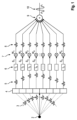
図1は、遅延和(DAS)法による従来のビームフォーミングを示す。例えば、トランスデューサ素子のアレイ4によって送信される超音波パルスに応答して、エコー3は、視野内の点構造(焦点)2から反射される。エコー3は、超音波トランスデューサのアレイ4によって記録される。このようにして取得された生RF信号5は、チャネルデータとも呼ばれ、各生RF信号5は1つのトランスデューサ素子によって取得されており、従って1つのチャネルに関連する。図1の例は、8つのチャネルを示す。ビームフォーミングに関して、チャネルデータ5は、ステップ6で補正される飛行時間であり、すなわち、トランスデューサアレイ4及び焦点2の形状に応じて、アレイ4によってエコー3が取得された異なる時間シフトt1、t2、・・・、tnが補正される。これらの時間アラインされたRF信号S1、・・・、Snは、ステップ7でアポダイゼーション重みw1、・・・、wnと乗算される。従来のDASビームフォーミングでは、これらの重みは予め設定されており、超音波画像のコンテントに適応していない。すなわち、これらの重みはRF信号に適応していない。重み付き信号8は、ステップ9で合計されて、ビームフォーミングされた出力信号10を生成する。このビームフォーミングされた出力信号10は、更に処理されて、1つのピクセルの画像データを生成することができる。
FIG. 1 shows conventional beamforming using the delay-and-sum (DAS) method. For example, in response to an ultrasound pulse transmitted by an array of transducer elements 4, echoes 3 are reflected from a point structure (focal point) 2 within the field of view.
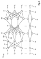
図2に適応ビームフォーミング方法を示す。この方法では、時間アラインされたRF信号18 S1、S2、・・・、Snは、ビームフォーミングアルゴリズム14によって、コンテント適応アポダイゼーション重み12を計算するために使用され、そのため、コンテント適応アポダイゼーション重み12は、DASビームフォーマにおいてそうであるように事前に決定されることはない。むしろ、信号は適応ビームフォーマ14、例えば最小分散ビームフォーマによって処理され、このビームフォーマは、画質を最大にするために最適重みを計算する。重み付けされたRF信号は、ステップ9で合計され、その結果、ビームフォーミングされた出力信号となる。
Figure 2 shows the adaptive beamforming method. In this method, the time-aligned RF signals 18 S 1 , S 2 , ..., S n are used by the
本発明によれば、従来の適応ビームフォーミングアルゴリズム/プロセッサ14は、ニューラルネットワークに置き換えられる。このようなニューラルネットワーク16の一例を図3に示す。この例示的なネットワークは層20、24、26、28、32、36に配置され、各層は多数のノードからなり、隣接する層間のノードはエッジによって接続される。各エッジ/接続は、第1のノードの値に対して実行される単純な演算に対応し、この演算の値は、接続されたノードの値に加算される。特に、ニューラルネットワークの各ノードには、実数又は複素数を値として割り当てることができる。
According to the invention, the conventional adaptive beamforming algorithm/
ニューラルネットワーク16は、入力として、複数の超音波トランスデューサから取得され、1ピクセルの計算に使用される時間アラインされたRF信号18 S1、S2、・・・、Snを受信する。入力層20内のノード21の数は、寄与するRF信号の数であるnに対応する。この実施形態では、出力層36のノード34の数nが入力層20のノード21の数nに対応する。コンテント適応アポディゼーション重みw1、・・・、wnを計算するために、入力値信号S1、S2、・・・、Snがニューラルネットワークを通して伝搬される。
The
この実施形態では入力層20は、完全結合層であり、すなわち、入力層の各ノード21はエッジ22によって、次の層24の各ノード23に接続される。この演算は行列乗算に対応し、入力層20の各値は、それを次の層24のノード23に接続するエッジの重みと乗算される。
In this embodiment, the
次の層は活性化層24であり、この例では反正規化層である。この反正規化器は、負の信号成分及び入力のダイナミックレンジを保持しながら、非線形性を効果的に導入する。入力の正の部分と負の部分とを連結するので、各ノード23は2つのエッジ24a及び24bによって示されるように、正の入力値を有するか負の入力値を有するかに応じて異なる出力を有するので、次の層26におけるノード25の数を事実上2倍にする。その他の点では、次の層26に含まれるノード25の構造は、活性化層24のノード23の構造と同等であり、すなわち、層24内の隣接するノード23間に相互接続はない。
The next layer is the
活性化層24に続く層26は、再び完全結合層であり、すなわち、この層の各ノード25は次の層28の各ノード27に接続される。この後続の層28は、前の層26よりも著しく少ないノード27を有する。ノードの数を減らすことによって、トレーニングされる必要があるパラメータ/重みの数が減らされる。これは、ネットワーク内の計算量を減少させ、オーバーフィッティングの制御につながる。例えば、3~6倍の次元削減があってもよく、図示の例ではファクタは3であり、すなわち、層28は先行する層26の3分の1のサイズを有する。有用な実施形態では、ファクタは5である。この場合も、層28は活性化層、すなわち、反正規化層であり、これは、サンプリングごとのL2正規化を2つのReLU活性化と組み合わせ、それによって、入力の正の部分と負の部分とを連結する。これにより、次の層32内のノード29の数が2倍になる。層32の各ノードは出力層36の各ノード34に接続されているので、この層32も完全結合層である。出力層36で出力される値は、コンテント適応アポディゼーション重みw1、・・・、wnである。
The
図3の実施形態ではニューラルネットワークが3つの完全結合層を有し(出力層36は次の層に値を伝播しないので、1としてカウントしない)、完全結合層は20、26、及び32と名付けられる。更に、ネットワークは2つの活性化層23及び28を有し、各々は、一対の完全結合層の間にある。他の有用な実施形態では、別の完全結合層と、それに続く活性化層、すなわち、合計4つの完全結合層及び3つの活性化層があってもよい。
In the embodiment of FIG. 3, the neural network has three fully connected layers (output layer 36 does not propagate values to the next layer, so it does not count as 1), and the fully connected layers are named 20, 26, and 32. It will be done. Furthermore, the network has two
図4には、本発明の方法の可能な実施例の概略図が示されている。(生の)RF信号が40で入力データとして示されており、データは、各々がいくつかの軸方向サンプルを有するいくつかのチャネルを有する。ステップ42において、生のRFデータは従来の方法を使用して時間アラインされ、異なる平面は異なるチャネルのデータを表す。この実施形態では、RF信号の飛行時間補正が事前に計算され、バッファに格納される。代替的に、飛行時間補正は、GPU内でオンザフライで計算することもでき、それによって、通信及びメモリオーバヘッドを低減する。更に、この実施態様では、1つのピクセルに関連する様々なチャネルからのすべてのデータ43が、ステップ44で新しいフォーマット45に再配置され、その結果、各ピクセルのデータ43は、NN内で単一のバッチとして処理されることができる。時間アラインされた及び再配置されたRF信号45にNN16を適用する次のステップは、46で示されている。スキップ接続48が入力(時間アラインされたRF信号)から出力50に追加され、ここで、時間アラインされたRF信号は、ステップ52で、NNによって生成されたアポディゼーション重みと乗算される。その結果、1つのピクセル54に関連するビームフォーミングされたデータ55が得られ、これは、超音波画像51を再構成するために使用される。NNによるビームフォーミング後、ビームフォーミングピクセルはその空間位置に従って再配置される。
FIG. 4 shows a schematic representation of a possible embodiment of the method of the invention. A (raw) RF signal is shown as input data at 40, the data having several channels each having a number of axial samples. At
この好適な実施形態のニューラルネットワーク16は、図5により詳細に示されている。各層の上には、その出力サイズ(寄与する128個のRF信号に対して)が示されている。完全結合層は暗い陰影で示され、反正規化層は白色で示され、ドロップアウト層(ネットワークのトレーニング中にのみ存在する)は明るい陰影で示されている。このNN16は、入力層及び出力層のための128個のノードと、内部層のための32個のノードとを備える4つの完全結合層を備える。この次元削減58は、第1の反正規化層に続いて8倍(23)、又は入力層倍であり、ネットワークに、よりコンパクトなデータ表現を見つけさせる。完全結合層(最後の層を除く)の各々の後には、反正規化層が続く。最後の完全結合層60は、出力層であるか、又は出力層(図示せず)に直接接続される。トレーニング中、完全結合層の各対の間に、例えば0.2の確率でドロップアウトが適用される。言い換えれば、トレーニング中に、ドロップアウトレイヤ内のノードの固定パーセンテージがドロップアウトされる。従って、ドロップアウト層は、ネットワークのトレーニング中にのみ存在する。ドロップアウトは、トレーニングデータに対するニューラルネットワークのオーバーフィッティングを低減するのに役立つ。
The
NNは、TensorFlow(Google、CA、USA)バックエンドを有するKeras APIを使用してPythonで実現されてもよい。訓練のために、Adamオプティマイザが、0.001の学習速度で使用され、それにより、単一画像に属するピクセルのバッチ全体にわたって確率的に最適化する。図5に示されるニューラルネットワークは、インビボ超音波画像データに対し実現され、訓練された。 The NN may be implemented in Python using the Keras API with a TensorFlow (Google, CA, USA) backend. For training, the Adam optimizer is used with a learning rate of 0.001, thereby stochastically optimizing over a batch of pixels belonging to a single image. The neural network shown in Figure 5 was implemented and trained on in vivo ultrasound image data.
図5に示すニューラルネットワークを訓練する場合、従来のアルゴリズムを使用する公知の適応ビームフォーミング技術によって計算されたアポダイゼーション重みを出力トレーニングデータとして使用することができる。入力トレーニングデータは、対応する時間アラインされたRF信号である。トレーニング中、NN16が、計算された出力データを生成するためにトレーニング入力データに適用される。計算された出力データと出力トレーニングデータとの間の比較は、ニューラルネットワーク16内の重みを、この場合、例えば0.0005~0.01の学習速度で再帰的に適応させるために使用される。オーバーフィッティングを防止するために、正規化の方法、すなわち、正規化に基づく人工的に計算されたデータ又は重み減衰を使用するノードのドロップアウト、が使用されることができる。
When training the neural network shown in FIG. 5, apodization weights calculated by known adaptive beamforming techniques using conventional algorithms can be used as output training data. The input training data are corresponding time-aligned RF signals. During training, the
図5のNNは、単一平面波伝送を用いて取得した画像についてテストされ、その結果が図6に示されている。Aで示される画像は、DASビームフォーマで再構成された画像を示す。画像Bは最小分散ビームフォーマを使用し、画像Cでは本発明の実現による深層学習ベースのビームフォーマが適用された。NNビームフォーマは、MVターゲットに匹敵する高コントラスト画像を著しく少ないクラッタで生成することができることが観察されることができる。更に、両方の適応技術は、DASと比較してCNR(コントラスト対雑音比)及び解像度が向上しており、後者についてはNNがMVターゲットを上回る結果となっており、これは、NNがトレーニングデータの統計量を平均化することで、ビームフォーミングプロセスに生成可能な事前情報を組み込むことができるためであると考えられる。より高品質の画像に関する訓練は、NNの性能を更に向上させることを可能にする。本発明のこの実施形態による方法は解像度とコントラストを比較するために、シミュレートされた画像についてもテストされた。分解能は、すべての点散乱体の半値全幅(FWHM)の平均を評価することによって評価された。コントラストは無エコーのシストの平均CNRを用いて評価された。その結果を表1に示す。従って、NNビームフォーマは、MVターゲットよりも著しく少ないクラッタで、高コントラスト画像を生成することができる。

図7は、本発明の一実施形態による、本発明の方法を実行するように構成された超音波システム100の概略図である。超音波システム100は、CPU104、GPU106及びデジタル記憶媒体108、例えばハードディスク又はソリッドステートディスクを有する通常の超音波ハードウェアユニット102を有する。コンピュータプログラムはCD-ROM110から、又はインターネット112を介して、ハードウェアユニットにロードされることができる。ハードウェアユニット102は、キーボード116及び任意選択でタッチパッド118を備えるユーザインターフェース114に接続される。また、タッチパッド118は、撮像パラメータを表示するための表示装置として機能してもよい。ハードウェアユニット102は超音波プローブ120に接続され、超音波トランスデューサ122のアレイを有し、これは、被検体又は患者(図示せず)からの生の超音波画像の取得を可能にする。超音波プローブ120で取得されたライブ画像124及びCPU104及び/又はGPUによって実行される本発明の方法に従ってビームフォーミングされ、スクリーン126上に表示され、スクリーン126は、任意の市販の表示ユニット、例えばスクリーン、テレビセット、フラットスクリーン、プロジェクタなどであってもよい。
FIG. 7 is a schematic diagram of an
更に、例えばインターネット112を介して、リモートコンピュータ又はサーバ128への接続が存在してもよい。本発明による方法は、ハードウェアユニット102のCPU104又はGPU106によって実行されてもよいが、遠隔サーバ128のプロセッサによって実行されてもよい。また、図8乃至図10は、アポディゼーション重みを計算するためにNNを使用せず、適応的にビームフォーミングされたRFデータを出力する、本発明の代替の態様に関する。この代替態様の目的は、適応ビームフォーミングの効果を画像ドメインで純粋に学習するだけではなく、チャネルごとのデータ(すなわち、RF信号)及びビームフォーミングRFデータを含む適応BFアルゴリズムの実際の数学的動作を学習することによって、所与の適応ビームフォーミング(BF)アルゴリズムの挙動をより正確に学習することとして記述されることができる。この代替態様は、MV又は上述の他の技術のような、計算的に高価な適応ビームフォーミングアルゴリズムを学習するために、多層パーセプトロン(MLP)を含む機械学習フレームワークを提供する。しかしながら、この機械学習フレームワークは、元の画像と適応的にビームフォーミングされた画像のピクセル値の間のマッピングとは対照的に、整列された複雑なチャネルごとのデータと適応的にビームフォーミングされたRFデータの間のマッピングを学習することを目的とする。
Additionally, there may be a connection to a remote computer or
MLPは、フィードフォワード人工ニューラルネットワークであり、入力データの組を取り込み、適切な出力の組にマッピングする。MLPは、非線形活性化関数を持つニューロンの複数の層からなり、各層は次の層に完全に接続されている。任意の連続マッピングy=f(x1,x2,..,xn)を表すために必要とされるレイヤの最小数は、入力層、隠れ層、及び出力層を有する3であることがすでに実証されている。3層MLP(又は、同等に1隠れ層MLP)は関数f:Rn→R1であり、ここで、nは、入力ベクトルxのサイズであり、lは、出力ベクトルf(x)のサイズであり、行列表記において、以下のように表される:


この代替態様で使用されるニューラルネットワークは、まず、Field IIシミュレーションによって生成されたトレーニングデータセットに基づいて適応ビームフォーミングアルゴリズムを学習するように訓練され、次に、訓練されたニューラルネットワークは、概念を証明するために2つの異なるテストデータセットに適用される。代替の態様は十分な量の入出力データ対が利用可能である限り、多くの他の計算的に高価な適応ビームフォーミング技法に一般化することができるフレームワークである。もう1つの態様は、限られた量のトレーニングデータセットから計算的に高価な適応ビームフォーミングアルゴリズムを学習し、推論を介してかなり低い計算コストで新しいデータセット上に学習したアルゴリズムを適用することができる機械学習フレームワークを提供する。本発明の代替的な側面は、時には平均以上の価格帯のGPUを使用してもリアルタイムで実行することが非常に難しい、計算量の多い適応ビームフォーミングアルゴリズムのリアルタイム処理を可能にするものでありうる。本発明の別の態様の主な構成要素は、チャネル当たりの時間アラインされた複素RFデータを複素ビームフォーミングされたRFデータにマッピングするニューラルネットワークである。多層パーセプトロン(MLP)、畳み込みニューラルネットワーク(CNN)、及び回帰及び/又は生成ネットワークなどのより高度なネットワークなどのいくつかのタイプのニューラルネットワークを使用して同様のタスクを実行することができるが、代替の態様はMLPモデルを使用して、機械学習/深層学習フレームワークを使用して高度な適応ビームフォーミング技術を学習及び適用することの実現可能性を実証する。MVビームフォーマはテストアルゴリズムとして使用されるが、ここで示したコア概念は他の適応ビームフォーミングアルゴリズムにも拡張できる。 The neural network used in this alternative is first trained to learn an adaptive beamforming algorithm based on the training dataset generated by the Field II simulation, and then the trained neural network It is applied to two different test data sets to prove it. An alternative aspect is a framework that can be generalized to many other computationally expensive adaptive beamforming techniques as long as a sufficient amount of input/output data pairs are available. Another aspect is that it is possible to learn a computationally expensive adaptive beamforming algorithm from a limited amount of training datasets and apply the learned algorithm on new datasets at a fairly low computational cost via inference. We provide a machine learning framework that can An alternative aspect of the present invention is to enable real-time processing of computationally intensive adaptive beamforming algorithms that are sometimes very difficult to execute in real-time even using above-average priced GPUs. sell. A key component of another aspect of the invention is a neural network that maps time-aligned complex RF data per channel to complex beamformed RF data. Although several types of neural networks can be used to perform similar tasks, such as multilayer perceptrons (MLPs), convolutional neural networks (CNNs), and more advanced networks such as regression and/or generative networks. An alternative aspect uses MLP models to demonstrate the feasibility of learning and applying advanced adaptive beamforming techniques using machine learning/deep learning frameworks. Although the MV beamformer is used as a test algorithm, the core concepts presented here can be extended to other adaptive beamforming algorithms.
本発明の代替の態様においてニューラルネットワークを訓練する際に使用される入出力対は元のビームフォーマ画像及びMVビームフォーマ画像からのピクセルではなく、むしろ、入力データは所与の深度における時間アラインされた複素チャネルRF信号から成り、出力データはMVビームフォーマのための対応する複素ビームフォーマ出力である。主なステップは図8に示されている。ステップ1では、ニューラルネットワークトレーニングのトレーニングデータセットが準備される。これは、入力としてのチャネル当たりの時間アラインされた複素データと、ターゲットとしての複素MVビームフォーミングされたデータとからなる。Nチャネルシステムの場合、M個の入力-出力対が、所与のピクセル位置における2N個の入力/チャネルデータ(実数及び虚数)と、対応するMVビームフォーマ出力(実数及び虚数)とから得られる。入力及び出力データは共に実部及び虚部を有する。従って、入力データ行列はM×2Nであり、出力データ行列はM×2である。MVビームフォーミングは、そのような入力-出力対を得るためにオフラインで実行されるべきである。MVビームフォーミングはデータ準備段階で一度だけ実行されるので、それに関連する計算上の負担は本方法の制限ではない。 In an alternative aspect of the invention, the input/output pairs used in training the neural network are not pixels from the original beamformer image and the MV beamformer image; rather, the input data is time-aligned at a given depth. The output data is the corresponding complex beamformer output for the MV beamformer. The main steps are shown in FIG. In step 1, a training dataset for neural network training is prepared. It consists of time-aligned complex data per channel as input and complex MV beamformed data as target. For an N-channel system, M input-output pairs are obtained from the 2N input/channel data (real and imaginary) at a given pixel location and the corresponding MV beamformer output (real and imaginary). . Both input and output data have real and imaginary parts. Therefore, the input data matrix is Mx2N and the output data matrix is Mx2. MV beamforming should be performed offline to obtain such input-output pairs. Since MV beamforming is performed only once during the data preparation stage, the computational burden associated with it is not a limitation of the method.
ステップ2では、トレーニングデータセットを使用して学習アルゴリズムを訓練する。このステップは、マッピングエラーが所定のレベルに収束するまで反復的に実行される。この概念を証明するために、MLPモデルが使用された。しかし、畳み込みニューラルネットワークを含むより高度なネットワークアーキテクチャを使用することができる。これについては、後の実施形態としてより詳細に説明する。
ステップ3では、学習アルゴリズムが以前には処理していなかった、チャネル当たりの時間アラインされた複素データの形のテストデータセットが導入される。訓練されたアルゴリズムは、入力データに作用して、その複素MVビームフォーマ出力を予測(又は推論)する。推論ステップは、加算及び乗算のみを使用してMVBFにおける計算集約的な動作を近似するので、MVBFの直接計算よりも著しく高速であることが期待される。例えば、標準DASに関連する計算量は、要素数O(N)に対して線形である。しかしながら、MVBFに対する計算量は、サブアレイサイズに比例し、最適開口重みを計算するために必要な行列反転によりO(L3)になる。しかし、MLPを使用すると、追加される計算負荷を大幅に低減することができ、潜在的に、リアルタイム処理をより実現可能にする。
In
いくつかの予備シミュレーション結果を図9及び10に示す。図9は,単一の大きな無響性嚢胞を含むファントムをシミュレートしたトレーニングデータセットで,原画像(左),ニューラルネットワーク画像(中),真のMVBF画像(右)を示している.64素子P4‐2位相ドアレイをシミュレートした。すべての画像は事前にスキャン変換された画像であり、すべての画像は60dBのダイナミックレンジで表示される。MVBF画像は、より微細なスペックルサイズ及び嚢胞内のサイドローブの減少した量を示すことに留意されたい。また、ニューラルネットワーク画像は嚢胞内のサイドローブが減少し、スペックルサイズがわずかに小さくなっていることを示している。 Some preliminary simulation results are shown in FIGS. 9 and 10. Figure 9 shows a training dataset simulating a phantom containing a single large anechoic cyst, showing the original image (left), neural network image (middle), and true MVBF image (right). A 64-element P4-2 phased array was simulated. All images are pre-scan converted images and all images are displayed with a 60 dB dynamic range. Note that MVBF images show finer speckle size and reduced amount of sidelobes within the cyst. Neural network images also show reduced sidelobes within the cyst and slightly smaller speckle size.
図10は、3つの小さい無エコーのシストを含む模擬ファントムからのテストデータセットを示す。原画像(左)、ニューラルネットワーク画像(中央)、及び真のMVBF画像(右)が示されている。64素子P4‐2位相アレイがシミュレートされた。すべての画像は、プリスキャンコンバート画像であり、すべての画像は、60dBのダイナミックレンジで表示される。MVBF画像は、無エコーのシストにおいて、より微細なスペックルサイズ及び減少したサイドローブを示すことに留意されたい。ニューラルネットワーク画像が同様の改善を示す。 FIG. 10 shows a test data set from a simulated phantom containing three small anechoic cysts. The original image (left), the neural network image (middle), and the true MVBF image (right) are shown. A 64-element P4-2 phased array was simulated. All images are pre-scan converted images and all images are displayed with a dynamic range of 60 dB. Note that MVBF images show finer speckle size and reduced sidelobes in anechoic cysts. Neural network images show similar improvements.
他のネットワークアーキテクチャが使用されることにより、適応ビームフォーミングアルゴリズムを学習することができる。重要なコンポーネントは、ネットワークが、チャネルごとの入力から、ビームフォーミングされた出力にマッピングすることである。例えば、畳み込みニューラルネットワークは、良好な結果を与えることが期待される。入力データは、チャネルごとの整列された実数(又は複素数)データである。処理は、ローカル(チャネルごとの関連データから1つのピクセル値を学習する)又はグローバル(アラインされたデータスタック全体からビームフォーミングされたRFフレーム全体を学習する)なものでありうる。ローカル処理は、入力データがいずれにせよローカルであるアルゴリズム(最小分散ビームフォーマなど)を模倣するのに適しているように思われる。十分なデータが提供されれば、グローバルアルゴリズムはまた、解剖学的構造情報を学習し、使用する可能性がなければならない。本発明のこの代替態様の理念に沿って、以下に、畳み込みニューラルネットワークを用いたローカルアプローチを説明する。各ピクセルごとのアラインされたチャネルごとのデータは、関心のあるサンプル深さのあたりで高速でクロッピングされ、(numTime*numElements)データ行列を生成する。時間のディメンジョンはステアリング効果に敏感であるように、典型的には数波長である。トレーニングデータセットサイズは、利用可能な画像の数におけるそのようなデータウィンドウの数によって決定される。1つの単一画像は、典型的には何十万もの独立したトレーニング入力-出力対をもたらすことができる。全入力データにわたる受信フィールドを有し、単一のスカラを出力する完全畳み込みニューラルネットワークは、関心のある深さで適応的にビームフォーミングされた値を学習するように訓練されることができる。 Other network architectures can be used to learn adaptive beamforming algorithms. The key component is that the network maps from per-channel inputs to beamformed outputs. For example, convolutional neural networks are expected to give good results. The input data is real (or complex) data aligned for each channel. Processing can be local (learning one pixel value from relevant data per channel) or global (learning the entire beamformed RF frame from the entire aligned data stack). Local processing seems suitable for imitating algorithms where the input data is local anyway (such as minimum variance beamformers). The global algorithm must also have the possibility to learn and use anatomical information if provided with sufficient data. In keeping with the philosophy of this alternative aspect of the invention, a local approach using convolutional neural networks is described below. The aligned per-channel data for each pixel is fast cropped around the sample depth of interest to produce a (numTime*numElements) data matrix. The time dimension is typically a few wavelengths, so that it is sensitive to steering effects. The training dataset size is determined by the number of such data windows in the number of available images. One single image can typically yield hundreds of thousands of independent training input-output pairs. A fully convolutional neural network with a receive field spanning all input data and outputting a single scalar can be trained to learn adaptively beamformed values at depths of interest.
上記の議論は単に本システムを例示することを意図しており、添付の特許請求の範囲を任意の特定の実施形態又は実施形態のグループに限定するものと解釈されるべきではない。従って、本システムは例示的な実施形態を参照して特に詳細に発明されてきたが、当業者であれば、以下の特許請求の範囲に記載される本システムのより広く意図された精神及び範囲から逸脱することなく、多数の修正及び代替実施形態を考案することができることも理解されたい。従って、本明細書及び図面は例示的なものであり、添付の請求項の範囲を限定することを意図したものではありません。 The above discussion is intended to be merely illustrative of the present system and should not be construed as limiting the scope of the appended claims to any particular embodiment or group of embodiments. Thus, while the present system has been invented in particular detail with reference to exemplary embodiments, those skilled in the art will appreciate the broader intended spirit and scope of the present system as set forth in the claims below. It should also be understood that numerous modifications and alternative embodiments may be devised without departing from the invention. Accordingly, the specification and drawings are in an illustrative sense and are not intended to limit the scope of the appended claims.
Claims (15)
a)超音波送信に応答して複数の超音波トランスデューサ素子によって取得されたRF信号を受信するステップと、
b)訓練済み人工ニューラルネットワークを前記RF信号に適用することによって、前記RF信号をビームフォーミングするためのコンテント適応アポダイゼーション重みを決定するステップと、
を有する方法。 A method for adaptive beamforming of ultrasound signals, the method comprising:
a) receiving RF signals acquired by the plurality of ultrasound transducer elements in response to the ultrasound transmission;
b) determining content-adaptive apodization weights for beamforming the RF signal by applying a trained artificial neural network to the RF signal;
How to have.
(a)入力トレーニングデータ又は超音波送信に応答して複数の超音波トランスデューサ素子によって取得されたRF信号を受信するステップと、
(b)出力トレーニングデータを受信するステップであって、前記出力トレーニングデータは、コンテント適応アポダイゼーション重みであり、前記コンテント適応アポダイゼーション重みが、コンテント適応ビームフォーミングアルゴリズムによってRF信号から計算されるか、又は前記出力トレーニングデータが前記コンテント適応ビームフォーミングアルゴリズムによって前記RF信号から計算されるビームフォーミングされた出力信号である、ステップと、
(c)前記入力トレーニングデータ及び前記出力トレーニングデータを使用することによって人工ニューラルネットワークを訓練するステップと、
(d)訓練済み人工ニューラルネットワークを提供するステップと、
を有する方法。 A method of providing a trained artificial neural network useful for content-adaptive beamforming of ultrasound signals, the method comprising:
(a) receiving RF signals acquired by the plurality of ultrasound transducer elements in response to input training data or ultrasound transmissions;
(b) receiving output training data, the output training data being content-adaptive apodization weights, the content-adaptive apodization weights being calculated from the RF signal by a content-adaptive beamforming algorithm; output training data is a beamformed output signal calculated from the RF signal by the content adaptive beamforming algorithm;
(c) training an artificial neural network by using the input training data and the output training data;
(d) providing a trained artificial neural network;
How to have.
a)超音波送信に応答して複数の超音波トランスデューサ素子によって取得されるRF信号を受信する第1のインターフェースと、
b)前記RF信号に訓練済み人工ニューラルネットワークを適用し、それによって前記RF信号をビームフォーミングするためのコンテント適応アポダイゼーション重みが生成され、前記RF信号に前記コンテント適応アポダイゼーション重みを適用してビームフォーミングされた出力信号を計算するように構成された計算ユニットと、
c)前記ビームフォーミングされた出力信号を出力する第2のインターフェースと、
を有するシステム。 A system for adaptive beamforming of ultrasound signals, the system comprising:
a) a first interface receiving RF signals acquired by the plurality of ultrasound transducer elements in response to the ultrasound transmission;
b) applying a trained artificial neural network to the RF signal, thereby generating content-adaptive apodization weights for beamforming the RF signal, applying the content-adaptive apodization weights to the RF signal to beamform the RF signal; a calculation unit configured to calculate an output signal;
c) a second interface that outputs the beamformed output signal;
A system with
Applications Claiming Priority (5)
| Application Number | Priority Date | Filing Date | Title |
|---|---|---|---|
| EP18202469.5 | 2018-10-25 | ||
| EP18202469 | 2018-10-25 | ||
| EP19164249.5 | 2019-03-21 | ||
| EP19164249.5A EP3712651A1 (en) | 2019-03-21 | 2019-03-21 | Method and system for adaptive beamforming of ultrasound signals |
| PCT/EP2019/078739 WO2020083918A1 (en) | 2018-10-25 | 2019-10-22 | Method and system for adaptive beamforming of ultrasound signals |
Publications (3)
| Publication Number | Publication Date |
|---|---|
| JP2022505511A JP2022505511A (en) | 2022-01-14 |
| JPWO2020083918A5 JPWO2020083918A5 (en) | 2022-08-24 |
| JP7359850B2 true JP7359850B2 (en) | 2023-10-11 |
Family
ID=68240760
Family Applications (1)
| Application Number | Title | Priority Date | Filing Date |
|---|---|---|---|
| JP2021521781A Active JP7359850B2 (en) | 2018-10-25 | 2019-10-22 | Method and system for adaptive beamforming of ultrasound signals |
Country Status (5)
| Country | Link |
|---|---|
| US (1) | US20210382157A1 (en) |
| EP (1) | EP3870999A1 (en) |
| JP (1) | JP7359850B2 (en) |
| CN (1) | CN112912758A (en) |
| WO (1) | WO2020083918A1 (en) |
Families Citing this family (7)
| Publication number | Priority date | Publication date | Assignee | Title |
|---|---|---|---|---|
| CN110874828B (en) * | 2020-01-20 | 2020-04-21 | 上海尽星生物科技有限责任公司 | Neural network model and ultrasonic beam forming method based on neural network model |
| CN111695297B (en) * | 2020-06-02 | 2022-08-02 | 哈尔滨工程大学 | Offshore surface air temperature inversion method |
| DE102020213900A1 (en) * | 2020-09-30 | 2022-03-31 | Siemens Healthcare Gmbh | Method for providing position information of a local high-frequency coil |
| WO2023147103A1 (en) * | 2022-01-30 | 2023-08-03 | Cloudstream Medical Imaging, Inc. | Time-shared transmission and continuous recording of ultrasound data for enhanced frame rates |
| EP4258016A1 (en) | 2022-04-07 | 2023-10-11 | Koninklijke Philips N.V. | A computer-implemented method for beamforming of ultrasound channel data |
| WO2023194523A1 (en) | 2022-04-07 | 2023-10-12 | Koninklijke Philips N.V. | A computer-implemented method for beamforming of ultrasound channel data |
| CN115952840A (en) * | 2023-03-09 | 2023-04-11 | 深圳时识科技有限公司 | Beam forming method, arrival direction identification method, device and chip thereof |
Citations (2)
| Publication number | Priority date | Publication date | Assignee | Title |
|---|---|---|---|---|
| US20170363725A1 (en) | 2014-12-19 | 2017-12-21 | University Of Rochester | Ultrasound system for high-speed and high resolution imaging applications |
| WO2018167101A1 (en) | 2017-03-13 | 2018-09-20 | Koninklijke Philips N.V. | Methods and systems for filtering ultrasound image clutter |
Family Cites Families (12)
| Publication number | Priority date | Publication date | Assignee | Title |
|---|---|---|---|---|
| EP0575716A1 (en) * | 1993-04-08 | 1993-12-29 | Andrzej Cichocki | A neural network and signal processing units |
| GB0209780D0 (en) * | 2002-04-29 | 2002-06-05 | Neural Technologies Ltd | Method of encoding data for decoding data from and constraining a neural network |
| US9320491B2 (en) * | 2011-04-18 | 2016-04-26 | The Trustees Of Columbia University In The City Of New York | Ultrasound devices methods and systems |
| US9092729B2 (en) * | 2011-08-11 | 2015-07-28 | Greenray Industries, Inc. | Trim effect compensation using an artificial neural network |
| JP6108499B2 (en) * | 2012-05-11 | 2017-04-05 | コーニンクレッカ フィリップス エヌ ヴェKoninklijke Philips N.V. | Method for imaging specular object and target anatomy in tissue using ultrasound and ultrasound imaging apparatus |
| AU2015247501B2 (en) * | 2014-04-18 | 2018-11-29 | Butterfly Network, Inc. | Ultrasonic imaging compression methods and apparatus |
| EP3195004A1 (en) * | 2014-08-13 | 2017-07-26 | B-K Medical ApS | Ultrasound signal analog beamformer / beamforming |
| CN110338844B (en) * | 2015-02-16 | 2022-04-19 | 深圳迈瑞生物医疗电子股份有限公司 | Three-dimensional imaging data display processing method and three-dimensional ultrasonic imaging method and system |
| US11222263B2 (en) * | 2016-07-28 | 2022-01-11 | Samsung Electronics Co., Ltd. | Neural network method and apparatus |
| WO2018127498A1 (en) * | 2017-01-05 | 2018-07-12 | Koninklijke Philips N.V. | Ultrasound imaging system with a neural network for image formation and tissue characterization |
| CN108574954A (en) * | 2017-03-08 | 2018-09-25 | 索尼公司 | Electronic equipment in wireless communication system and method |
| EP3581961A1 (en) * | 2018-06-13 | 2019-12-18 | Technische Universität München | Method and apparatus for ultrasound imaging with improved beamforming |
-
2019
- 2019-10-22 CN CN201980070368.6A patent/CN112912758A/en active Pending
- 2019-10-22 JP JP2021521781A patent/JP7359850B2/en active Active
- 2019-10-22 WO PCT/EP2019/078739 patent/WO2020083918A1/en unknown
- 2019-10-22 US US17/288,043 patent/US20210382157A1/en active Pending
- 2019-10-22 EP EP19787007.4A patent/EP3870999A1/en active Pending
Patent Citations (2)
| Publication number | Priority date | Publication date | Assignee | Title |
|---|---|---|---|---|
| US20170363725A1 (en) | 2014-12-19 | 2017-12-21 | University Of Rochester | Ultrasound system for high-speed and high resolution imaging applications |
| WO2018167101A1 (en) | 2017-03-13 | 2018-09-20 | Koninklijke Philips N.V. | Methods and systems for filtering ultrasound image clutter |
Non-Patent Citations (1)
| Title |
|---|
| LUCHIES, Adam C., et al.,Deep Neural Networks for Ultrasound Beamforming,IEEE TRANSACTIONS ON MEDICAL IMAGING,米国,IEEE,2018年09月,VOL.37, NO.9,pp.2010-2021 |
Also Published As
| Publication number | Publication date |
|---|---|
| US20210382157A1 (en) | 2021-12-09 |
| JP2022505511A (en) | 2022-01-14 |
| EP3870999A1 (en) | 2021-09-01 |
| CN112912758A (en) | 2021-06-04 |
| WO2020083918A1 (en) | 2020-04-30 |
Similar Documents
| Publication | Publication Date | Title |
|---|---|---|
| JP7359850B2 (en) | Method and system for adaptive beamforming of ultrasound signals | |
| Luijten et al. | Adaptive ultrasound beamforming using deep learning | |
| US11886978B2 (en) | Neural network medical image system | |
| Zhang et al. | Ultrasound image reconstruction from plane wave radio-frequency data by self-supervised deep neural network | |
| JP7345208B2 (en) | Image reconstruction method based on learning nonlinear mapping | |
| EP3712651A1 (en) | Method and system for adaptive beamforming of ultrasound signals | |
| Goudarzi et al. | Ultrasound beamforming using mobilenetv2 | |
| US20210272339A1 (en) | Systems and Methods for Generating and Estimating Unknown and Unacquired Ultrasound Data | |
| Luchies et al. | Training improvements for ultrasound beamforming with deep neural networks | |
| EP3754558A1 (en) | Method and system for generating a synthetic elastrography image | |
| Mor et al. | A unified deep network for beamforming and speckle reduction in plane wave imaging: A simulation study | |
| Deylami et al. | Iterative minimum variance beamformer with low complexity for medical ultrasound imaging | |
| Nair et al. | One-step deep learning approach to ultrasound image formation and image segmentation with a fully convolutional neural network | |
| Goudarzi et al. | Inverse problem of ultrasound beamforming with denoising-based regularized solutions | |
| Mamistvalov et al. | Deep unfolded recovery of sub-nyquist sampled ultrasound images | |
| Luijten et al. | Ultrasound signal processing: from models to deep learning | |
| US11158052B2 (en) | Systems and methods for ultrasonic imaging | |
| US11478225B2 (en) | Apparatus and method for processing ultrasound image in various sensor conditions | |
| van Sloun et al. | 1 Deep learning for ultrasound beamforming | |
| Khan et al. | Switchable deep beamformer for ultrasound imaging using adain | |
| Goudarzi et al. | A unifying approach to inverse problems of ultrasound beamforming and deconvolution | |
| CN115100069A (en) | Ultrasonic image reconstruction method, system, device and medium | |
| CN110554393A (en) | high-contrast minimum variance imaging method based on deep learning | |
| Goudarzi et al. | Pruning mobilenetv2 for efficient implementation of minimum variance beamforming | |
| Vienneau et al. | An improved training scheme for deep neural network ultrasound beamforming |
Legal Events
| Date | Code | Title | Description |
|---|---|---|---|
| A521 | Request for written amendment filed |
Free format text: JAPANESE INTERMEDIATE CODE: A523 Effective date: 20220816 |
|
| A621 | Written request for application examination |
Free format text: JAPANESE INTERMEDIATE CODE: A621 Effective date: 20220816 |
|
| A131 | Notification of reasons for refusal |
Free format text: JAPANESE INTERMEDIATE CODE: A131 Effective date: 20230124 |
|
| A521 | Request for written amendment filed |
Free format text: JAPANESE INTERMEDIATE CODE: A523 Effective date: 20230306 |
|
| A131 | Notification of reasons for refusal |
Free format text: JAPANESE INTERMEDIATE CODE: A131 Effective date: 20230608 |
|
| A521 | Request for written amendment filed |
Free format text: JAPANESE INTERMEDIATE CODE: A523 Effective date: 20230831 |
|
| TRDD | Decision of grant or rejection written | ||
| A01 | Written decision to grant a patent or to grant a registration (utility model) |
Free format text: JAPANESE INTERMEDIATE CODE: A01 Effective date: 20230912 |
|
| A61 | First payment of annual fees (during grant procedure) |
Free format text: JAPANESE INTERMEDIATE CODE: A61 Effective date: 20230928 |
|
| R150 | Certificate of patent or registration of utility model |
Ref document number: 7359850 Country of ref document: JP Free format text: JAPANESE INTERMEDIATE CODE: R150 |