EP3410175A1 - Display device and display method - Google Patents
Display device and display method Download PDFInfo
- Publication number
- EP3410175A1 EP3410175A1 EP17878397.3A EP17878397A EP3410175A1 EP 3410175 A1 EP3410175 A1 EP 3410175A1 EP 17878397 A EP17878397 A EP 17878397A EP 3410175 A1 EP3410175 A1 EP 3410175A1
- Authority
- EP
- European Patent Office
- Prior art keywords
- transparent member
- light beam
- display
- image
- concave mirror
- Prior art date
- Legal status (The legal status is an assumption and is not a legal conclusion. Google has not performed a legal analysis and makes no representation as to the accuracy of the status listed.)
- Granted
Links
- 238000000034 method Methods 0.000 title claims description 17
- 230000003287 optical effect Effects 0.000 claims abstract description 40
- 239000011521 glass Substances 0.000 description 6
- 239000005340 laminated glass Substances 0.000 description 2
- 239000007787 solid Substances 0.000 description 2
- 230000005540 biological transmission Effects 0.000 description 1
- 238000009792 diffusion process Methods 0.000 description 1
- 230000004907 flux Effects 0.000 description 1
- 239000012634 fragment Substances 0.000 description 1
- 239000004973 liquid crystal related substance Substances 0.000 description 1
- 239000011347 resin Substances 0.000 description 1
- 229920005989 resin Polymers 0.000 description 1
- 230000000007 visual effect Effects 0.000 description 1
Images

Classifications
-
- G—PHYSICS
- G02—OPTICS
- G02B—OPTICAL ELEMENTS, SYSTEMS OR APPARATUS
- G02B27/00—Optical systems or apparatus not provided for by any of the groups G02B1/00 - G02B26/00, G02B30/00
- G02B27/01—Head-up displays
- G02B27/0101—Head-up displays characterised by optical features
-
- B—PERFORMING OPERATIONS; TRANSPORTING
- B60—VEHICLES IN GENERAL
- B60K—ARRANGEMENT OR MOUNTING OF PROPULSION UNITS OR OF TRANSMISSIONS IN VEHICLES; ARRANGEMENT OR MOUNTING OF PLURAL DIVERSE PRIME-MOVERS IN VEHICLES; AUXILIARY DRIVES FOR VEHICLES; INSTRUMENTATION OR DASHBOARDS FOR VEHICLES; ARRANGEMENTS IN CONNECTION WITH COOLING, AIR INTAKE, GAS EXHAUST OR FUEL SUPPLY OF PROPULSION UNITS IN VEHICLES
- B60K35/00—Arrangement of adaptations of instruments
-
- B60K35/23—
-
- B—PERFORMING OPERATIONS; TRANSPORTING
- B60—VEHICLES IN GENERAL
- B60R—VEHICLES, VEHICLE FITTINGS, OR VEHICLE PARTS, NOT OTHERWISE PROVIDED FOR
- B60R11/00—Arrangements for holding or mounting articles, not otherwise provided for
- B60R11/02—Arrangements for holding or mounting articles, not otherwise provided for for radio sets, television sets, telephones, or the like; Arrangement of controls thereof
-
- G—PHYSICS
- G01—MEASURING; TESTING
- G01C—MEASURING DISTANCES, LEVELS OR BEARINGS; SURVEYING; NAVIGATION; GYROSCOPIC INSTRUMENTS; PHOTOGRAMMETRY OR VIDEOGRAMMETRY
- G01C21/00—Navigation; Navigational instruments not provided for in groups G01C1/00 - G01C19/00
- G01C21/26—Navigation; Navigational instruments not provided for in groups G01C1/00 - G01C19/00 specially adapted for navigation in a road network
- G01C21/34—Route searching; Route guidance
- G01C21/36—Input/output arrangements for on-board computers
- G01C21/3626—Details of the output of route guidance instructions
- G01C21/365—Guidance using head up displays or projectors, e.g. virtual vehicles or arrows projected on the windscreen or on the road itself
-
- G—PHYSICS
- G02—OPTICS
- G02B—OPTICAL ELEMENTS, SYSTEMS OR APPARATUS
- G02B27/00—Optical systems or apparatus not provided for by any of the groups G02B1/00 - G02B26/00, G02B30/00
- G02B27/0018—Optical systems or apparatus not provided for by any of the groups G02B1/00 - G02B26/00, G02B30/00 with means for preventing ghost images
-
- G—PHYSICS
- G02—OPTICS
- G02B—OPTICAL ELEMENTS, SYSTEMS OR APPARATUS
- G02B5/00—Optical elements other than lenses
- G02B5/08—Mirrors
- G02B5/10—Mirrors with curved faces
-
- B60K2360/23—
-
- B60K2360/334—
-
- G—PHYSICS
- G02—OPTICS
- G02B—OPTICAL ELEMENTS, SYSTEMS OR APPARATUS
- G02B27/00—Optical systems or apparatus not provided for by any of the groups G02B1/00 - G02B26/00, G02B30/00
- G02B27/01—Head-up displays
- G02B27/0101—Head-up displays characterised by optical features
- G02B2027/0118—Head-up displays characterised by optical features comprising devices for improving the contrast of the display / brillance control visibility
- G02B2027/012—Head-up displays characterised by optical features comprising devices for improving the contrast of the display / brillance control visibility comprising devices for attenuating parasitic image effects
- G02B2027/0121—Parasitic image effect attenuation by suitable positioning of the parasitic images
Definitions
- the present disclosure relates to a display apparatus and a display method, and specifically relates to a display apparatus and a display method for presenting a virtual image.
- a head-up display (HUD) for a vehicle is an apparatus for displaying information such as the speed of the vehicle, a warning, or a guidance display in a navigation system by reflecting this information in a windshield of the vehicle or a combiner, which is a semi-transparent reflection plate.
- HUD head-up display
- video images are presented in such a way that they overlap the front visual field of a driver, whereby the driver is able to check vehicle information and the like without moving his or her line of sight much. Therefore, more and more vehicles have been equipped with the HUD as a safe display apparatus.
- An object of the present disclosure is to provide a display apparatus and a display method capable of suppressing occurrence of a double image even when the transparent member to present the image is not processed into a wedge shape.
- This embodiment provides a display apparatus including: a display surface configured to display an image; and a concave mirror configured to reflect light beams from the display surface toward a transparent member reflecting some of the light beams that have been input thereto and transmitting the remaining light beams that have been input thereto, in which an optical path of a first light beam after the first light beam is reflected in the transparent member coincides with an optical path of a second light beam after the second light beam is reflected in the transparent member by the reflection in the concave mirror, the first light beam reaching the transparent member from one point on the display surface and reflecting on a front surface of the transparent member, and the second light beam reaching the transparent member from the one point and reflecting on a rear surface of the transparent member, and a virtual image of the image is presented by the transparent member.
- This embodiment further provides a display apparatus including: a display surface configured to display an image; and a concave mirror configured to reflect light beams from the display surface toward a transparent member reflecting some of the light beams that have been input thereto and transmitting the remaining light beams that have been input thereto, in which a first light beam and a second light beam that reach the transparent member from one point on the display surface are incident on the transparent member in parallel to each other by the reflection in the concave mirror, and a virtual image of the image is presented by the transparent member.
- This embodiment further provides a display method including: displaying an image on a display surface; reflecting light beams from the display surface toward a transparent member by a concave mirror, the transparent member reflecting some of the light beams that have been input thereto and transmitting the remaining light beams that have been input thereto; and presenting a virtual image of the image by the transparent member, in which, in the reflection by the concave mirror, the reflection is performed in such a way that an optical path of a first light beam after the first light beam is reflected in the transparent member coincides with an optical path of a second light beam after the second light beam is reflected in the transparent member by the reflection in the concave mirror, the first light beam reaching the transparent member from one point on the display surface and reflecting on a front surface of the transparent member, and the second light beam reaching the transparent member from the one point and reflecting on a rear surface of the transparent member.
- This embodiment further provides a display method including: displaying an image on a display surface; reflecting light beams from the display surface toward a transparent member by a concave mirror, the transparent member reflecting some of the light beams that have been input thereto and transmitting the remaining light beams that have been input thereto; and presenting a virtual image of the image by the transparent member, in which, in the reflection by the concave mirror, the reflection is performed in such a way that a first light beam and a second light beam that reach the transparent member from one point on the display surface are incident on the transparent member in parallel to each other.
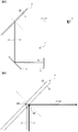
- Fig. 1 is a schematic view showing a principle of occurrence of a double image.
- Fig. 1 shows a state in which light from an object 4 is reflected in a transparent member 2 such as a windshield having a front surface and a rear surface parallel to each other and the reflected light reaches an eye 3 of a user.
- a transparent member 2 such as a windshield having a front surface and a rear surface parallel to each other and the reflected light reaches an eye 3 of a user.
- a first light beam that is reflected on a front surface 21 of the transparent member and reaches the eye 3 is denoted by a light beam L1
- a second light beam that is reflected on a rear surface 22 of the transparent member and reaches the eye 3 is denoted by a light beam L2.
- the light beam L1 is shown by a thick solid arrow and the light beam L2 is shown by a thin solid arrow.
- the light beam L1 is reflected on the front surface 21 without passing inside the transparent member 2 and then reaches the eye 3.
- the light beam L2 is refracted when it is incident on the transparent member 2, passes inside the transparent member 2, reflected on the rear surface 22, refracted again, and then reaches the eye 3, as shown in Fig. 1 .
- both of the two light beams L1 and L2 be light beams output from one point P.
- the light beam L2 from the point P may be bent in the middle of the optical path before it is incident on the transparent member 2.
- Fig. 3 is a schematic view showing one example of a structure of a display apparatus 1 according to this embodiment.
- Fig. 3 shows, besides the display apparatus 1, a transparent member 2 and an eye 3 of the user, in order to facilitate understanding.
- the display apparatus 1 is formed, for example, as a head-up display, and includes a display surface 10 and a concave mirror 11.
- the display apparatus 1 is, for example, mounted on a vehicle, and presents various kinds of information such as vehicle information to a driver.
- the display apparatus 1 reflects light from an image displayed on the display surface 10 in the transparent member 2, thereby presenting a virtual image of the image displayed on the display surface 10 to the user.
- the display surface 10 displays images by light emission. While the display surface 10 is a display surface of a flat panel display 12 such as a liquid crystal display (LCD), a plasma display, or an organic EL display in this embodiment, the display surface 10 may be a screen on which an image is projected by a projector. In this embodiment, an image signal is input to the flat panel display 12 and the flat panel display 12 displays the image in accordance with the image signal on the display surface 10.
- a flat panel display 12 such as a liquid crystal display (LCD), a plasma display, or an organic EL display
- the display surface 10 may be a screen on which an image is projected by a projector.
- an image signal is input to the flat panel display 12 and the flat panel display 12 displays the image in accordance with the image signal on the display surface 10.
- the transparent member 2 which is a member that reflects some of light beams that have been input thereto and transmits the remaining light beams that have been input thereto, presents a virtual image of the image of the display surface 10. While the transparent member 2 is a windshield in this embodiment, this is merely an example and the transparent member 2 may be a combiner or the like. The transparent member 2 does not have a wedge shape to prevent the double image.
- the transparent member 2 is formed of, for example, a glass having a flat plate shape or a curved shape having a front surface 21 and a rear surface 22 parallel to each other.
- the light of the image projected onto the display surface 10 is reflected in the transparent member 2 and reaches the eye 3. Further, the light that has passed the transparent member 2 from the side of the rear surface 22 also reaches the eye 3. Therefore, these light beams overlay (overlap) and are then incident on the eye 3. Accordingly, the user is able to see both the video image information and the situation to the front of the vehicle at the same time.
- the concave mirror 11 is provided in the middle of the optical path from the display surface 10 to the transparent member 2, and reflects the light beams from the display surface 10 toward the transparent member 2.
- the concave mirror 11 is provided in such a way that the optical path of the first light beam L1 after the first light beam L1 that reaches the transparent member 2 from a desired one point P on the display surface and is reflected on the front surface 21 of the transparent member 2 is reflected in the transparent member 2 and the optical path of the second light beam L2 after the second light beam L2 that reaches the transparent member 2 from one point P and is reflected on the rear surface 22 of the transparent member 2 is reflected in the transparent member 2 coincide with each other, as shown in Fig. 3 .
- the concave mirror 11 is provided in such a way that the first light beam L1 and the second light beam L2 that reach the transparent member 2 from one point P on the display surface 10 are incident on the transparent member 2 in parallel to each other, as shown in Fig. 4 .
- the concave mirror 11 is installed while the distance on the optical path between the reflection surface of the concave mirror 11 having a predetermined curvature and the display surface 10 is adjusted in such a way that the optical paths after both of the light beams are reflected in the transparent member 2 coincide with each other; that is, in such a way that both of the light beams are incident on the transparent member 2 in parallel to each other.
- the target to be adjusted is not limited to the distance between the concave mirror 11 and the display surface 10 and may be the curvature of the concave mirror 11.
- the curvature of the concave mirror 11 provided in such a way that it is spaced apart from the display surface 10 by a predetermined distance on the optical path may be adjusted in such a way that the optical paths after both of the light beams are reflected in the transparent member 2 coincide with each other; that is, in such a way that both of the light beams are incident on the transparent member 2 in parallel to each other. Both the curvature and the distance may be adjusted.
- the optical paths may not completely coincide with each other, although it is preferable that the optical paths completely coincide with each other.
- the light beams may not be completely in parallel to each other, although it is preferable that the light beams be completely in parallel to each other.
- Fig. 5 is an enlarged view of an area near the concave mirror 11 shown in Fig. 3 .
- the light beam L1 from the point P on the display surface 10 is reflected in a point M1 on the reflection surface of the concave mirror 11 and the light beam L2 from the point P on the display surface 10 is reflected in a point M2 on the reflection surface of the concave mirror 11.
- the traveling direction of the light beam L1 that is reflected in the point M1 and proceeds toward the transparent member 2 and the traveling direction of the light beam L2 that is reflected in the point M2 and proceeds toward the transparent member 2 are aligned to be parallel to each other by the reflection in the concave mirror 11. Therefore, as shown in Fig.
- the light beam L1 and the light beam L2 that reach the transparent member 2 from one point P on the display surface 10 are made incident on the transparent member 2 in parallel to each other.
- the light beam L1 is reflected in a point M3 of the front surface 21 without passing inside the transparent member 2.
- the light beam L2 is refracted when it is incident on the transparent member 2, passes the inside of the transparent member 2, reflected in a point M4 of the rear surface 22, refracted again, and then emitted from the point M3 of the front surface 21 of the transparent member 2.
- the optical path of the light beam L1 and the optical path of the light beam L2 from the transparent member 2 to the eye 3 coincide with each other.
- the concave mirror 11 is typically used to enlarge the image and to present the virtual image at a further distance, in this embodiment, as described above, besides these functions, it is used to suppress occurrence of the double image.
- the display apparatus 1 makes the optical path of the light beam L1 after the light beam L1 reflected on the front surface 21 of the transparent member 2 is reflected in the transparent member 2 and the optical path of the light beam L2 after the light beam L2 reflected on the rear surface 22 of the transparent member 2 is reflected in the transparent member 2 coincide with each other by the concave mirror 11.
- the display apparatus 1 makes the light beam L1 and the light beam L2 that reach the transparent member 2 from the display surface 10 incident on the transparent member 2 in parallel to each other by the concave mirror 11. Therefore, according to the display apparatus 1, it is possible to suppress occurrence of double image even when the transparent member 2 to present the images is not processed into a wedge shape.
- An automotive windshield has a structure in which an intermediate film made of resin is held by two glasses so that even when the glass is broken, the fragments thereof will not be scattered.
- a special windshield formed of a laminated glass including the intermediate film having a wedge angle it is possible to prevent the double image.
- this laminated glass is more expensive than normal glasses.
- a normal windshield that does not have a wedge shape can be used as the transparent member 2. Accordingly, it is possible to suppress occurrence of the double image even when the expensive windshield is not used.
- the display surface 10 is not limited to the display surface of the flat panel display 12 and may be a screen on which an image is projected by a projector.
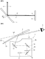
- Fig. 6 is a schematic view showing one example of a structure of a display apparatus 7 according to a modified example.
- the display apparatus 7 includes a light emitting unit 71, a first plane mirror 72, a screen 73, a second plane mirror 74, a concave mirror 11, and a case 75.
- the light beam L3 corresponds to the light beam L1 and the light beam L2 described above.
- the light emitting unit 71 raster-scans the laser beam using an optical scanner (not shown) that includes a scanning mirror, thereby displaying an image on the screen 73.
- the light beam L3 emitted from the light emitting unit 71 is reflected in the first plane mirror 72, which causes the optical path thereof to be bent, and is then incident on the screen 73.
- the light beam L3 forms an intermediate image of the display image on the screen 73.
- the screen 73 is a light-transmission type screen, and may be, for example, a diffusion plate or a micro lens array.
- the light beam L3 emitted from the screen 73 is reflected in the second plane mirror 74, which causes the optical path thereof to be bent, and is then incident on the concave mirror 11.
- the light beam L3 reflected in the concave mirror 11 is emitted to the outside of the case 75 and is then made incident on the transparent member 2.
- the light beam L3 emitted from an opening of the case 75 and reflected by the transparent member 2 and a light beam L4 that has transmitted the transparent member 2 overlap each other due to the presence of the transparent member 2 and then the overlapping light beams reach the eye 3 of the user.
- the user sees the image displayed on the display apparatus 7 as a virtual image overlapping with the landscape seen over the transparent member 2.
- the curvature of the concave mirror 11 or the distance on the optical path from the display surface 10 of the screen 73 to the concave mirror 11 is adjusted. Therefore, the optical path of the first light beam after the first light beam that reaches the transparent member 2 from one point on the display surface 10 of the screen 73 and is reflected on the front surface of the transparent member 2 is reflected in the transparent member 2 and the optical path of the second light beam after the second light beam that reaches the transparent member 2 from this point and is reflected on the rear surface 22 of the transparent member 2 is reflected in the transparent member 2 coincide with each other.
- the distance on the optical path from the display surface 10 of the screen 73 becomes equal to the sum of the distance from the screen 73 to the second plane mirror 74 and the distance from the second plane mirror 74 to the concave mirror 11.
- a plane mirror may be provided on the optical path that connects the concave mirror 11 and the display surface 10.
- the display apparatus is not limited to being used for an on-vehicle head-up display and may be used for a head-mounted display such as a helmet-mounted display or a spectacle type display.
- the present disclosure is applicable to a display apparatus and a display method, and has an industrial applicability.
Abstract
Description
- The present disclosure relates to a display apparatus and a display method, and specifically relates to a display apparatus and a display method for presenting a virtual image.
- A head-up display (HUD) for a vehicle is an apparatus for displaying information such as the speed of the vehicle, a warning, or a guidance display in a navigation system by reflecting this information in a windshield of the vehicle or a combiner, which is a semi-transparent reflection plate. In the HUD, video images are presented in such a way that they overlap the front visual field of a driver, whereby the driver is able to check vehicle information and the like without moving his or her line of sight much. Therefore, more and more vehicles have been equipped with the HUD as a safe display apparatus.
- In general, when a video image is reflected on a transparent object such as glass, due to the light beam reflected on the front surface of the transparent object and the light beam reflected on the rear surface of the transparent object, a user such as a driver sees video images overlapping each other with some deviation between them. This phenomenon is called a double image. As a method of cancelling the double image, a method of changing the reflection angles of the light beams by forming a small angle having a wedge shape between the front surface and the rear surface of the transparent object such as glass to thereby make the two images coincide with each other has been known (e.g., Patent Literature 1 and Patent Literature 2).
-
- [Patent Literature 1] Published Japanese Translation of
PCT International Publication for Patent Application, No. 2011-505330 - [Patent Literature 2] Japanese Unexamined Patent Application Publication No.
2012-58688 - When the double image is prevented by forming a small angle having a wedge shape in the windshield like the method disclosed in Patent Literature 1 etc., such a special process needs to be performed on the windshield. Further, in the method disclosed in
Patent Literature 2, the combiner needs to be processed into a wedge shape. That is, in the methods disclosed in these literatures, the transparent member to present the image needs to be processed into a wedge shape. Therefore, a technique for preventing the double image even when the transparent member to present the image is not processed into a wedge shape is required. - An object of the present disclosure is to provide a display apparatus and a display method capable of suppressing occurrence of a double image even when the transparent member to present the image is not processed into a wedge shape.
- This embodiment provides a display apparatus including: a display surface configured to display an image; and a concave mirror configured to reflect light beams from the display surface toward a transparent member reflecting some of the light beams that have been input thereto and transmitting the remaining light beams that have been input thereto, in which an optical path of a first light beam after the first light beam is reflected in the transparent member coincides with an optical path of a second light beam after the second light beam is reflected in the transparent member by the reflection in the concave mirror, the first light beam reaching the transparent member from one point on the display surface and reflecting on a front surface of the transparent member, and the second light beam reaching the transparent member from the one point and reflecting on a rear surface of the transparent member, and a virtual image of the image is presented by the transparent member.
- This embodiment further provides a display apparatus including: a display surface configured to display an image; and a concave mirror configured to reflect light beams from the display surface toward a transparent member reflecting some of the light beams that have been input thereto and transmitting the remaining light beams that have been input thereto, in which a first light beam and a second light beam that reach the transparent member from one point on the display surface are incident on the transparent member in parallel to each other by the reflection in the concave mirror, and a virtual image of the image is presented by the transparent member.
- This embodiment further provides a display method including: displaying an image on a display surface; reflecting light beams from the display surface toward a transparent member by a concave mirror, the transparent member reflecting some of the light beams that have been input thereto and transmitting the remaining light beams that have been input thereto; and presenting a virtual image of the image by the transparent member, in which, in the reflection by the concave mirror, the reflection is performed in such a way that an optical path of a first light beam after the first light beam is reflected in the transparent member coincides with an optical path of a second light beam after the second light beam is reflected in the transparent member by the reflection in the concave mirror, the first light beam reaching the transparent member from one point on the display surface and reflecting on a front surface of the transparent member, and the second light beam reaching the transparent member from the one point and reflecting on a rear surface of the transparent member.
- This embodiment further provides a display method including: displaying an image on a display surface; reflecting light beams from the display surface toward a transparent member by a concave mirror, the transparent member reflecting some of the light beams that have been input thereto and transmitting the remaining light beams that have been input thereto; and presenting a virtual image of the image by the transparent member, in which, in the reflection by the concave mirror, the reflection is performed in such a way that a first light beam and a second light beam that reach the transparent member from one point on the display surface are incident on the transparent member in parallel to each other.
- According to this embodiment, it is possible to provide a display apparatus and a display method capable of suppressing occurrence of a double image even when the transparent member to present the image is not processed into a wedge shape.
-
-
Fig. 1 is a schematic view showing a principle of occurrence of a double image; -
Fig. 2 is a schematic view showing an optical path to prevent an image from being seen as a double image; -
Fig. 3 is a schematic view showing one example of a structure of a display apparatus according to an embodiment; -
Fig. 4 is an enlarged view of an area near a transmission member inFig. 3 ; -
Fig. 5 is an enlarged view of an area near a concave mirror inFig. 3 ; and -
Fig. 6 is a schematic view showing one example of a structure of a display apparatus according to a modified example. - First, the content of the matters studied by the inventors in advance will be explained.
Fig. 1 is a schematic view showing a principle of occurrence of a double image.Fig. 1 shows a state in which light from anobject 4 is reflected in atransparent member 2 such as a windshield having a front surface and a rear surface parallel to each other and the reflected light reaches aneye 3 of a user. Of a light flux from a point P on theobject 4, a first light beam that is reflected on afront surface 21 of the transparent member and reaches theeye 3 is denoted by a light beam L1 and a second light beam that is reflected on arear surface 22 of the transparent member and reaches theeye 3 is denoted by a light beam L2. InFig. 1 , the light beam L1 is shown by a thick solid arrow and the light beam L2 is shown by a thin solid arrow. The same is true forFigs. 2 ,4 , and5 that will be described later. The light beam L1 is reflected on thefront surface 21 without passing inside thetransparent member 2 and then reaches theeye 3. On the other hand, the light beam L2 is refracted when it is incident on thetransparent member 2, passes inside thetransparent member 2, reflected on therear surface 22, refracted again, and then reaches theeye 3, as shown inFig. 1 . In this case, since there is a difference between the angles of the two light beams from thetransparent member 2 to theeye 3, a deviation occurs between the position of avirtual image 6A created by the light beam L1 and the position of avirtual image 6B created by the light beam L2. Therefore, theeye 3 of the user sees the virtual images overlapping each other with some deviation between them. The phenomenon of the double image thus occurs. - Therefore, as shown in
Fig. 2 , when the two light beams L1 and L2 reflected in thetransparent member 2 reach theeye 3 from one direction, one virtual image 6 is seen, rather than the double image. That is, it is required that the light beam L1 reflected on thefront surface 21 of thetransparent member 2 and the light beam L1 reflected on therear surface 22 overlap each other and reach theeye 3. In this case, the two light beams L1 and L2 before they are reflected in thetransparent member 2 are parallel to each other. This can be derived from Snell's law. In other words, when the two light beams L1 and L2 are incident on thetransparent member 2 in parallel to each other, the light beams overlap each other after the reflection. In order to allow the user to see the two images made by the two light beams L1 and L2 that coincide with each other with no deviation between them, it is required that both of the two light beams L1 and L2 be light beams output from one point P. In order to achieve this structure, as shown inFig. 2 , the light beam L2 from the point P may be bent in the middle of the optical path before it is incident on thetransparent member 2. - In the following description, with reference to the drawings, an embodiment of the present disclosure will be explained.
Fig. 3 is a schematic view showing one example of a structure of a display apparatus 1 according to this embodiment.Fig. 3 shows, besides the display apparatus 1, atransparent member 2 and aneye 3 of the user, in order to facilitate understanding. The display apparatus 1 is formed, for example, as a head-up display, and includes adisplay surface 10 and aconcave mirror 11. The display apparatus 1 is, for example, mounted on a vehicle, and presents various kinds of information such as vehicle information to a driver. The display apparatus 1 reflects light from an image displayed on thedisplay surface 10 in thetransparent member 2, thereby presenting a virtual image of the image displayed on thedisplay surface 10 to the user. - The
display surface 10 displays images by light emission. While thedisplay surface 10 is a display surface of aflat panel display 12 such as a liquid crystal display (LCD), a plasma display, or an organic EL display in this embodiment, thedisplay surface 10 may be a screen on which an image is projected by a projector. In this embodiment, an image signal is input to theflat panel display 12 and theflat panel display 12 displays the image in accordance with the image signal on thedisplay surface 10. - The
transparent member 2, which is a member that reflects some of light beams that have been input thereto and transmits the remaining light beams that have been input thereto, presents a virtual image of the image of thedisplay surface 10. While thetransparent member 2 is a windshield in this embodiment, this is merely an example and thetransparent member 2 may be a combiner or the like. Thetransparent member 2 does not have a wedge shape to prevent the double image. Thetransparent member 2 is formed of, for example, a glass having a flat plate shape or a curved shape having afront surface 21 and arear surface 22 parallel to each other. - The light of the image projected onto the
display surface 10 is reflected in thetransparent member 2 and reaches theeye 3. Further, the light that has passed thetransparent member 2 from the side of therear surface 22 also reaches theeye 3. Therefore, these light beams overlay (overlap) and are then incident on theeye 3. Accordingly, the user is able to see both the video image information and the situation to the front of the vehicle at the same time. - The
concave mirror 11 is provided in the middle of the optical path from thedisplay surface 10 to thetransparent member 2, and reflects the light beams from thedisplay surface 10 toward thetransparent member 2. Theconcave mirror 11 is provided in such a way that the optical path of the first light beam L1 after the first light beam L1 that reaches thetransparent member 2 from a desired one point P on the display surface and is reflected on thefront surface 21 of thetransparent member 2 is reflected in thetransparent member 2 and the optical path of the second light beam L2 after the second light beam L2 that reaches thetransparent member 2 from one point P and is reflected on therear surface 22 of thetransparent member 2 is reflected in thetransparent member 2 coincide with each other, as shown inFig. 3 . In other words, theconcave mirror 11 is provided in such a way that the first light beam L1 and the second light beam L2 that reach thetransparent member 2 from one point P on thedisplay surface 10 are incident on thetransparent member 2 in parallel to each other, as shown inFig. 4 . - More specifically, the
concave mirror 11 is installed while the distance on the optical path between the reflection surface of theconcave mirror 11 having a predetermined curvature and thedisplay surface 10 is adjusted in such a way that the optical paths after both of the light beams are reflected in thetransparent member 2 coincide with each other; that is, in such a way that both of the light beams are incident on thetransparent member 2 in parallel to each other. The target to be adjusted is not limited to the distance between theconcave mirror 11 and thedisplay surface 10 and may be the curvature of theconcave mirror 11. That is, the curvature of theconcave mirror 11 provided in such a way that it is spaced apart from thedisplay surface 10 by a predetermined distance on the optical path may be adjusted in such a way that the optical paths after both of the light beams are reflected in thetransparent member 2 coincide with each other; that is, in such a way that both of the light beams are incident on thetransparent member 2 in parallel to each other. Both the curvature and the distance may be adjusted. The optical paths may not completely coincide with each other, although it is preferable that the optical paths completely coincide with each other. In a similar way, the light beams may not be completely in parallel to each other, although it is preferable that the light beams be completely in parallel to each other. -
Fig. 5 is an enlarged view of an area near theconcave mirror 11 shown inFig. 3 . As shown inFig. 5 , the light beam L1 from the point P on thedisplay surface 10 is reflected in a point M1 on the reflection surface of theconcave mirror 11 and the light beam L2 from the point P on thedisplay surface 10 is reflected in a point M2 on the reflection surface of theconcave mirror 11. In this case, the traveling direction of the light beam L1 that is reflected in the point M1 and proceeds toward thetransparent member 2 and the traveling direction of the light beam L2 that is reflected in the point M2 and proceeds toward thetransparent member 2 are aligned to be parallel to each other by the reflection in theconcave mirror 11. Therefore, as shown inFig. 4 , the light beam L1 and the light beam L2 that reach thetransparent member 2 from one point P on thedisplay surface 10 are made incident on thetransparent member 2 in parallel to each other. The light beam L1 is reflected in a point M3 of thefront surface 21 without passing inside thetransparent member 2. On the other hand, the light beam L2 is refracted when it is incident on thetransparent member 2, passes the inside of thetransparent member 2, reflected in a point M4 of therear surface 22, refracted again, and then emitted from the point M3 of thefront surface 21 of thetransparent member 2. In this case, the optical path of the light beam L1 and the optical path of the light beam L2 from thetransparent member 2 to theeye 3 coincide with each other. While only the optical paths of the light emitted from the point P on thedisplay surface 10 are shown inFigs. 3 to 5 for the sake of clarity of explanation, the optical paths of the light emitted from each point on thedisplay surface 10 are adjusted by theconcave mirror 11 in a similar way. Therefore, occurrence of the double image for the image displayed on thedisplay surface 10 is suppressed. - While the
concave mirror 11 is typically used to enlarge the image and to present the virtual image at a further distance, in this embodiment, as described above, besides these functions, it is used to suppress occurrence of the double image. As described above, the display apparatus 1 makes the optical path of the light beam L1 after the light beam L1 reflected on thefront surface 21 of thetransparent member 2 is reflected in thetransparent member 2 and the optical path of the light beam L2 after the light beam L2 reflected on therear surface 22 of thetransparent member 2 is reflected in thetransparent member 2 coincide with each other by theconcave mirror 11. In other words, the display apparatus 1 makes the light beam L1 and the light beam L2 that reach thetransparent member 2 from thedisplay surface 10 incident on thetransparent member 2 in parallel to each other by theconcave mirror 11. Therefore, according to the display apparatus 1, it is possible to suppress occurrence of double image even when thetransparent member 2 to present the images is not processed into a wedge shape. - It is known to use a special windshield in a vehicle that is equipped with a head-up display that directly reflects the image in the windshield in order to prevent the double image. An automotive windshield has a structure in which an intermediate film made of resin is held by two glasses so that even when the glass is broken, the fragments thereof will not be scattered. By using a special windshield formed of a laminated glass including the intermediate film having a wedge angle, it is possible to prevent the double image. However, there is a problem that this laminated glass is more expensive than normal glasses. On the other hand, in this embodiment, a normal windshield that does not have a wedge shape can be used as the
transparent member 2. Accordingly, it is possible to suppress occurrence of the double image even when the expensive windshield is not used. - As described above, the
display surface 10 is not limited to the display surface of theflat panel display 12 and may be a screen on which an image is projected by a projector.Fig. 6 is a schematic view showing one example of a structure of a display apparatus 7 according to a modified example. The display apparatus 7 includes alight emitting unit 71, afirst plane mirror 72, ascreen 73, asecond plane mirror 74, aconcave mirror 11, and acase 75. - With reference to
Fig. 6 , an optical path until a light beam L3 emitted from thelight emitting unit 71 reaches theeye 3 of the user will be explained. The light beam L3 corresponds to the light beam L1 and the light beam L2 described above. Thelight emitting unit 71 raster-scans the laser beam using an optical scanner (not shown) that includes a scanning mirror, thereby displaying an image on thescreen 73. The light beam L3 emitted from thelight emitting unit 71 is reflected in thefirst plane mirror 72, which causes the optical path thereof to be bent, and is then incident on thescreen 73. The light beam L3 forms an intermediate image of the display image on thescreen 73. Thescreen 73 is a light-transmission type screen, and may be, for example, a diffusion plate or a micro lens array. - The light beam L3 emitted from the
screen 73 is reflected in thesecond plane mirror 74, which causes the optical path thereof to be bent, and is then incident on theconcave mirror 11. The light beam L3 reflected in theconcave mirror 11 is emitted to the outside of thecase 75 and is then made incident on thetransparent member 2. - In the display apparatus 7, the light beam L3 emitted from an opening of the
case 75 and reflected by thetransparent member 2 and a light beam L4 that has transmitted thetransparent member 2 overlap each other due to the presence of thetransparent member 2 and then the overlapping light beams reach theeye 3 of the user. The user sees the image displayed on the display apparatus 7 as a virtual image overlapping with the landscape seen over thetransparent member 2. - In this modified example as well, similar to the aforementioned embodiment, the curvature of the
concave mirror 11 or the distance on the optical path from thedisplay surface 10 of thescreen 73 to theconcave mirror 11 is adjusted. Therefore, the optical path of the first light beam after the first light beam that reaches thetransparent member 2 from one point on thedisplay surface 10 of thescreen 73 and is reflected on the front surface of thetransparent member 2 is reflected in thetransparent member 2 and the optical path of the second light beam after the second light beam that reaches thetransparent member 2 from this point and is reflected on therear surface 22 of thetransparent member 2 is reflected in thetransparent member 2 coincide with each other. Accordingly, in the display apparatus 7 as well, it is possible to suppress occurrence of a double image even when the transparent member to present the images is not processed into a wedge shape. InFig. 6 , the distance on the optical path from thedisplay surface 10 of thescreen 73 becomes equal to the sum of the distance from thescreen 73 to thesecond plane mirror 74 and the distance from thesecond plane mirror 74 to theconcave mirror 11. - The present disclosure is not limited to the aforementioned embodiment and may be changed as appropriate without departing from the spirit of the present disclosure. For example, as shown in
Fig. 6 , a plane mirror may be provided on the optical path that connects theconcave mirror 11 and thedisplay surface 10. Further, the display apparatus is not limited to being used for an on-vehicle head-up display and may be used for a head-mounted display such as a helmet-mounted display or a spectacle type display. - This application is based upon and claims the benefit of priority from Japanese Patent Application No.
2016-236405, filed on December 6, 2016 - The present disclosure is applicable to a display apparatus and a display method, and has an industrial applicability.
-
- 1, 7
- DISPLAY APPARATUS
- 2
- TRANSPARENT MEMBER
- 10
- DISPLAY SURFACE
- 11
- CONCAVE MIRROR
- 21
- FRONT SURFACE
- 22
- REAR SURFACE
- 73
- SCREEN
Claims (7)
- A display apparatus comprising:a display surface configured to display an image; anda concave mirror configured to reflect light beams from the display surface toward a transparent member reflecting some of the light beams that have been input thereto and transmitting the remaining light beams that have been input thereto, whereinan optical path of a first light beam after the first light beam is reflected in the transparent member coincides with an optical path of a second light beam after the second light beam is reflected in the transparent member by the reflection in the concave mirror, the first light beam reaching the transparent member from one point on the display surface and reflecting on a front surface of the transparent member, and the second light beam reaching the transparent member from the one point and reflecting on a rear surface of the transparent member, anda virtual image of the image is presented by the transparent member.
- The display apparatus according to Claim 1, wherein a curvature of the concave mirror or a distance on an optical path from the concave mirror to the display surface is adjusted in such a way that an optical path of the first light beam after the first light beam is reflected in the transparent member coincides with an optical path of the second light beam after the second light beam is reflected in the transparent member.
- A display apparatus comprising:a display surface configured to display an image; anda concave mirror configured to reflect light beams from the display surface toward a transparent member reflecting some of the light beams that have been input thereto and transmitting the remaining light beams that have been input thereto, whereina first light beam and a second light beam that reach the transparent member from one point on the display surface are incident on the transparent member in parallel to each other by the reflection in the concave mirror, anda virtual image of the image is presented by the transparent member.
- The display apparatus according to Claim 3, wherein a curvature of the concave mirror or a distance on an optical path from the concave mirror to the display surface is adjusted in such a way that the first light beam and the second light beam are incident on the transparent member in parallel to each other.
- The display apparatus according to any one of Claims 1 to 4, wherein the transparent member is a windshield.
- A display method comprising:displaying an image on a display surface;reflecting light beams from the display surface toward a transparent member by a concave mirror, the transparent member reflecting some of the light beams that have been input thereto and transmitting the remaining light beams that have been input thereto; andpresenting a virtual image of the image by the transparent member,wherein, in the reflection by the concave mirror, the reflection is performed in such a way that an optical path of a first light beam after the first light beam is reflected in the transparent member coincides with an optical path of a second light beam after the second light beam is reflected in the transparent member by the reflection in the concave mirror, the first light beam reaching the transparent member from one point on the display surface and reflecting on a front surface of the transparent member, and the second light beam reaching the transparent member from the one point and reflecting on a rear surface of the transparent member.
- A display method comprising:displaying an image on a display surface;reflecting light beams from the display surface toward a transparent member by a concave mirror, the transparent member reflecting some of the light beams that have been input thereto and transmitting the remaining light beams that have been input thereto; andpresenting a virtual image of the image by the transparent member,wherein, in the reflection by the concave mirror, the reflection is performed in such a way that a first light beam and a second light beam that reach the transparent member from one point on the display surface are incident on the transparent member in parallel to each other.
Priority Applications (1)
| Application Number | Priority Date | Filing Date | Title |
|---|---|---|---|
| EP19205852.7A EP3677949B1 (en) | 2016-12-06 | 2017-10-03 | Display apparatus and display method |
Applications Claiming Priority (2)
| Application Number | Priority Date | Filing Date | Title |
|---|---|---|---|
| JP2016236405A JP6365646B2 (en) | 2016-12-06 | 2016-12-06 | Display device and display method |
| PCT/JP2017/035999 WO2018105214A1 (en) | 2016-12-06 | 2017-10-03 | Display device and display method |
Related Child Applications (2)
| Application Number | Title | Priority Date | Filing Date |
|---|---|---|---|
| EP19205852.7A Division EP3677949B1 (en) | 2016-12-06 | 2017-10-03 | Display apparatus and display method |
| EP19205852.7A Division-Into EP3677949B1 (en) | 2016-12-06 | 2017-10-03 | Display apparatus and display method |
Publications (3)
| Publication Number | Publication Date |
|---|---|
| EP3410175A4 EP3410175A4 (en) | 2018-12-05 |
| EP3410175A1 true EP3410175A1 (en) | 2018-12-05 |
| EP3410175B1 EP3410175B1 (en) | 2019-12-18 |
Family
ID=62491810
Family Applications (2)
| Application Number | Title | Priority Date | Filing Date |
|---|---|---|---|
| EP17878397.3A Active EP3410175B1 (en) | 2016-12-06 | 2017-10-03 | Display device and display method |
| EP19205852.7A Active EP3677949B1 (en) | 2016-12-06 | 2017-10-03 | Display apparatus and display method |
Family Applications After (1)
| Application Number | Title | Priority Date | Filing Date |
|---|---|---|---|
| EP19205852.7A Active EP3677949B1 (en) | 2016-12-06 | 2017-10-03 | Display apparatus and display method |
Country Status (6)
| Country | Link |
|---|---|
| US (1) | US10884242B2 (en) |
| EP (2) | EP3410175B1 (en) |
| JP (1) | JP6365646B2 (en) |
| KR (1) | KR102215823B1 (en) |
| CN (1) | CN108496108B (en) |
| WO (1) | WO2018105214A1 (en) |
Families Citing this family (4)
| Publication number | Priority date | Publication date | Assignee | Title |
|---|---|---|---|---|
| JP6717264B2 (en) * | 2017-06-08 | 2020-07-01 | 株式会社Jvcケンウッド | Virtual image display device, intermediate image forming unit, and image display light generation unit |
| JP2020020914A (en) * | 2018-07-31 | 2020-02-06 | マクセル株式会社 | Information display device and information display method |
| JP6734340B2 (en) * | 2018-10-01 | 2020-08-05 | 本田技研工業株式会社 | Display device, display control method, and program |
| JP2022093857A (en) | 2020-12-14 | 2022-06-24 | 株式会社Jvcケンウッド | Display device |
Family Cites Families (28)
| Publication number | Priority date | Publication date | Assignee | Title |
|---|---|---|---|---|
| JPH0659787B2 (en) * | 1986-03-28 | 1994-08-10 | 矢崎総業株式会社 | Automotive heads-up display device |
| US4973139A (en) * | 1989-04-07 | 1990-11-27 | Hughes Aircraft Company | Automotive head-up display |
| US5013134A (en) * | 1989-09-28 | 1991-05-07 | Hughes Aircraft Company | Ghost-free automotive head-up display employing a wedged windshield |
| JPH03125623U (en) | 1990-04-03 | 1991-12-18 | ||
| JPH0456633A (en) * | 1990-06-26 | 1992-02-24 | Kansei Corp | Head up display device |
| JP3573765B2 (en) * | 1993-03-18 | 2004-10-06 | カルソニックカンセイ株式会社 | Vehicle head-up display device |
| FR2717795B1 (en) * | 1994-03-22 | 1996-05-24 | Saint Gobain Vitrage | Vehicle glazing and plastic sheet used in this glazing. |
| US6327084B1 (en) * | 1997-06-30 | 2001-12-04 | Central Glass Company, Limited | Display system where polarized light impinges on platelike laminate at brewster's angle or emerges therefrom at angle equal thereto |
| WO1999063389A1 (en) * | 1998-06-03 | 1999-12-09 | Nippon Sheet Glass Co., Ltd. | Head-up display device and laminated glass for head-up display device |
| US6262848B1 (en) * | 1999-04-29 | 2001-07-17 | Raytheon Company | Head-up display |
| US6359737B1 (en) * | 2000-07-28 | 2002-03-19 | Generals Motors Corporation | Combined head-up display |
| JP4355134B2 (en) * | 2002-10-09 | 2009-10-28 | 矢崎総業株式会社 | Vehicle display device |
| US7158095B2 (en) * | 2003-07-17 | 2007-01-02 | Big Buddy Performance, Inc. | Visual display system for displaying virtual images onto a field of vision |
| JP2005156678A (en) * | 2003-11-21 | 2005-06-16 | Nippon Seiki Co Ltd | Combiner and head-up display using the combiner |
| JP2007223883A (en) * | 2005-12-26 | 2007-09-06 | Asahi Glass Co Ltd | Laminated glass for vehicle |
| TR201807499T4 (en) | 2007-12-07 | 2018-06-21 | Saint Gobain | Curved vehicle windscreen made of laminated glass. |
| JP2011207845A (en) * | 2010-03-30 | 2011-10-20 | Kyocera Mita Corp | Fluorenylidene derivative, manufacturing method of the same, and electrophotographic photoreceptor |
| JP5802002B2 (en) * | 2010-09-13 | 2015-10-28 | 矢崎総業株式会社 | Head-up display |
| JP5999434B2 (en) * | 2013-03-27 | 2016-09-28 | 日本精機株式会社 | Head-up display device |
| US9182659B2 (en) * | 2013-09-06 | 2015-11-10 | Taiwan Semiconductor Manufacturing Company, Ltd. | Extreme ultraviolet lithography process and mask |
| JP6340807B2 (en) * | 2014-02-05 | 2018-06-13 | 株式会社リコー | Image display device and moving body |
| CN204360020U (en) * | 2015-01-19 | 2015-05-27 | 上海芯天电子有限公司 | A kind of device eliminating automobile head-up display projection image ghost image |
| JP6569898B2 (en) * | 2015-06-30 | 2019-09-04 | パナソニックIpマネジメント株式会社 | Display device and display method |
| KR20170008430A (en) * | 2015-07-14 | 2017-01-24 | 엘지전자 주식회사 | Head up display |
| KR101868684B1 (en) * | 2016-02-12 | 2018-07-17 | 엘지전자 주식회사 | Head Up Display for vehicle |
| JP7009735B2 (en) * | 2016-09-08 | 2022-01-26 | 株式会社リコー | Image display device and object device |
| CN206856500U (en) * | 2017-02-14 | 2018-01-09 | 深圳前海智云谷科技有限公司 | A kind of head-up display device of integral type |
| CN207752232U (en) * | 2017-10-30 | 2018-08-21 | 苏州车萝卜汽车电子科技有限公司 | Windscreen formula head-up display device |
-
2016
- 2016-12-06 JP JP2016236405A patent/JP6365646B2/en active Active
-
2017
- 2017-10-03 KR KR1020187021283A patent/KR102215823B1/en active IP Right Grant
- 2017-10-03 EP EP17878397.3A patent/EP3410175B1/en active Active
- 2017-10-03 EP EP19205852.7A patent/EP3677949B1/en active Active
- 2017-10-03 CN CN201780008010.1A patent/CN108496108B/en active Active
- 2017-10-03 WO PCT/JP2017/035999 patent/WO2018105214A1/en active Application Filing
-
2018
- 2018-11-08 US US16/184,819 patent/US10884242B2/en active Active
Also Published As
| Publication number | Publication date |
|---|---|
| KR102215823B1 (en) | 2021-02-15 |
| CN108496108A (en) | 2018-09-04 |
| WO2018105214A1 (en) | 2018-06-14 |
| US10884242B2 (en) | 2021-01-05 |
| EP3410175A4 (en) | 2018-12-05 |
| JP2018092050A (en) | 2018-06-14 |
| CN108496108B (en) | 2021-05-14 |
| EP3677949A1 (en) | 2020-07-08 |
| JP6365646B2 (en) | 2018-08-01 |
| EP3410175B1 (en) | 2019-12-18 |
| EP3677949B1 (en) | 2022-02-16 |
| KR20190050736A (en) | 2019-05-13 |
| US20190079286A1 (en) | 2019-03-14 |
Similar Documents
| Publication | Publication Date | Title |
|---|---|---|
| US10884242B2 (en) | Display apparatus and display method | |
| EP2905649B1 (en) | Head-up display apparatus | |
| US20210033774A1 (en) | Image display device | |
| US11175500B2 (en) | Display device and display method of the same | |
| EP3276395B1 (en) | Head-up display | |
| WO2015159523A1 (en) | Heads-up display and moving body equipped with heads-up display | |
| EP3133436A1 (en) | Heads-up display and moving body equipped with heads-up display | |
| US20160150218A1 (en) | Combined structure for head up display system and driver monitoring system | |
| WO2019044072A1 (en) | Information display device | |
| WO2015122473A1 (en) | Head-up display device | |
| CN108919494B (en) | Head-up display device and automobile | |
| WO2017061016A1 (en) | Information display device | |
| JP2018505435A (en) | Head-up display with adjustable viewing window | |
| JP2018530771A (en) | Compact head-up display | |
| US10324287B2 (en) | Heads-up display device | |
| WO2018207630A1 (en) | Headup display device | |
| CN113970845A (en) | Multi-focal plane head-up display device | |
| KR20170008431A (en) | Head up display | |
| KR102087804B1 (en) | Virtual display | |
| KR101642747B1 (en) | Apparatus and method for head up display | |
| KR20170087590A (en) | Combiner for head up display | |
| JP2018501512A (en) | Head-up display with horizontal image generation device |
Legal Events
| Date | Code | Title | Description |
|---|---|---|---|
| STAA | Information on the status of an ep patent application or granted ep patent |
Free format text: STATUS: THE INTERNATIONAL PUBLICATION HAS BEEN MADE |
|
| PUAI | Public reference made under article 153(3) epc to a published international application that has entered the european phase |
Free format text: ORIGINAL CODE: 0009012 |
|
| STAA | Information on the status of an ep patent application or granted ep patent |
Free format text: STATUS: REQUEST FOR EXAMINATION WAS MADE |
|
| 17P | Request for examination filed |
Effective date: 20180830 |
|
| A4 | Supplementary search report drawn up and despatched |
Effective date: 20181030 |
|
| AK | Designated contracting states |
Kind code of ref document: A1 Designated state(s): AL AT BE BG CH CY CZ DE DK EE ES FI FR GB GR HR HU IE IS IT LI LT LU LV MC MK MT NL NO PL PT RO RS SE SI SK SM TR |
|
| AX | Request for extension of the european patent |
Extension state: BA ME |
|
| GRAP | Despatch of communication of intention to grant a patent |
Free format text: ORIGINAL CODE: EPIDOSNIGR1 |
|
| STAA | Information on the status of an ep patent application or granted ep patent |
Free format text: STATUS: GRANT OF PATENT IS INTENDED |
|
| DAV | Request for validation of the european patent (deleted) | ||
| DAX | Request for extension of the european patent (deleted) | ||
| INTG | Intention to grant announced |
Effective date: 20190729 |
|
| GRAS | Grant fee paid |
Free format text: ORIGINAL CODE: EPIDOSNIGR3 |
|
| GRAA | (expected) grant |
Free format text: ORIGINAL CODE: 0009210 |
|
| STAA | Information on the status of an ep patent application or granted ep patent |
Free format text: STATUS: THE PATENT HAS BEEN GRANTED |
|
| AK | Designated contracting states |
Kind code of ref document: B1 Designated state(s): AL AT BE BG CH CY CZ DE DK EE ES FI FR GB GR HR HU IE IS IT LI LT LU LV MC MK MT NL NO PL PT RO RS SE SI SK SM TR |
|
| REG | Reference to a national code |
Ref country code: CH Ref legal event code: EP |
|
| REG | Reference to a national code |
Ref country code: IE Ref legal event code: FG4D |
|
| REG | Reference to a national code |
Ref country code: DE Ref legal event code: R096 Ref document number: 602017009959 Country of ref document: DE |
|
| REG | Reference to a national code |
Ref country code: AT Ref legal event code: REF Ref document number: 1215262 Country of ref document: AT Kind code of ref document: T Effective date: 20200115 |
|
| REG | Reference to a national code |
Ref country code: NL Ref legal event code: MP Effective date: 20191218 |
|
| PG25 | Lapsed in a contracting state [announced via postgrant information from national office to epo] |
Ref country code: NO Free format text: LAPSE BECAUSE OF FAILURE TO SUBMIT A TRANSLATION OF THE DESCRIPTION OR TO PAY THE FEE WITHIN THE PRESCRIBED TIME-LIMIT Effective date: 20200318 Ref country code: GR Free format text: LAPSE BECAUSE OF FAILURE TO SUBMIT A TRANSLATION OF THE DESCRIPTION OR TO PAY THE FEE WITHIN THE PRESCRIBED TIME-LIMIT Effective date: 20200319 Ref country code: LT Free format text: LAPSE BECAUSE OF FAILURE TO SUBMIT A TRANSLATION OF THE DESCRIPTION OR TO PAY THE FEE WITHIN THE PRESCRIBED TIME-LIMIT Effective date: 20191218 Ref country code: FI Free format text: LAPSE BECAUSE OF FAILURE TO SUBMIT A TRANSLATION OF THE DESCRIPTION OR TO PAY THE FEE WITHIN THE PRESCRIBED TIME-LIMIT Effective date: 20191218 Ref country code: BG Free format text: LAPSE BECAUSE OF FAILURE TO SUBMIT A TRANSLATION OF THE DESCRIPTION OR TO PAY THE FEE WITHIN THE PRESCRIBED TIME-LIMIT Effective date: 20200318 Ref country code: SE Free format text: LAPSE BECAUSE OF FAILURE TO SUBMIT A TRANSLATION OF THE DESCRIPTION OR TO PAY THE FEE WITHIN THE PRESCRIBED TIME-LIMIT Effective date: 20191218 Ref country code: LV Free format text: LAPSE BECAUSE OF FAILURE TO SUBMIT A TRANSLATION OF THE DESCRIPTION OR TO PAY THE FEE WITHIN THE PRESCRIBED TIME-LIMIT Effective date: 20191218 |
|
| REG | Reference to a national code |
Ref country code: LT Ref legal event code: MG4D |
|
| PG25 | Lapsed in a contracting state [announced via postgrant information from national office to epo] |
Ref country code: RS Free format text: LAPSE BECAUSE OF FAILURE TO SUBMIT A TRANSLATION OF THE DESCRIPTION OR TO PAY THE FEE WITHIN THE PRESCRIBED TIME-LIMIT Effective date: 20191218 Ref country code: HR Free format text: LAPSE BECAUSE OF FAILURE TO SUBMIT A TRANSLATION OF THE DESCRIPTION OR TO PAY THE FEE WITHIN THE PRESCRIBED TIME-LIMIT Effective date: 20191218 |
|
| PG25 | Lapsed in a contracting state [announced via postgrant information from national office to epo] |
Ref country code: AL Free format text: LAPSE BECAUSE OF FAILURE TO SUBMIT A TRANSLATION OF THE DESCRIPTION OR TO PAY THE FEE WITHIN THE PRESCRIBED TIME-LIMIT Effective date: 20191218 |
|
| PG25 | Lapsed in a contracting state [announced via postgrant information from national office to epo] |
Ref country code: PT Free format text: LAPSE BECAUSE OF FAILURE TO SUBMIT A TRANSLATION OF THE DESCRIPTION OR TO PAY THE FEE WITHIN THE PRESCRIBED TIME-LIMIT Effective date: 20200513 Ref country code: EE Free format text: LAPSE BECAUSE OF FAILURE TO SUBMIT A TRANSLATION OF THE DESCRIPTION OR TO PAY THE FEE WITHIN THE PRESCRIBED TIME-LIMIT Effective date: 20191218 Ref country code: RO Free format text: LAPSE BECAUSE OF FAILURE TO SUBMIT A TRANSLATION OF THE DESCRIPTION OR TO PAY THE FEE WITHIN THE PRESCRIBED TIME-LIMIT Effective date: 20191218 Ref country code: CZ Free format text: LAPSE BECAUSE OF FAILURE TO SUBMIT A TRANSLATION OF THE DESCRIPTION OR TO PAY THE FEE WITHIN THE PRESCRIBED TIME-LIMIT Effective date: 20191218 Ref country code: NL Free format text: LAPSE BECAUSE OF FAILURE TO SUBMIT A TRANSLATION OF THE DESCRIPTION OR TO PAY THE FEE WITHIN THE PRESCRIBED TIME-LIMIT Effective date: 20191218 |
|
| PG25 | Lapsed in a contracting state [announced via postgrant information from national office to epo] |
Ref country code: SM Free format text: LAPSE BECAUSE OF FAILURE TO SUBMIT A TRANSLATION OF THE DESCRIPTION OR TO PAY THE FEE WITHIN THE PRESCRIBED TIME-LIMIT Effective date: 20191218 Ref country code: SK Free format text: LAPSE BECAUSE OF FAILURE TO SUBMIT A TRANSLATION OF THE DESCRIPTION OR TO PAY THE FEE WITHIN THE PRESCRIBED TIME-LIMIT Effective date: 20191218 Ref country code: IS Free format text: LAPSE BECAUSE OF FAILURE TO SUBMIT A TRANSLATION OF THE DESCRIPTION OR TO PAY THE FEE WITHIN THE PRESCRIBED TIME-LIMIT Effective date: 20200418 |
|
| REG | Reference to a national code |
Ref country code: DE Ref legal event code: R097 Ref document number: 602017009959 Country of ref document: DE |
|
| REG | Reference to a national code |
Ref country code: AT Ref legal event code: MK05 Ref document number: 1215262 Country of ref document: AT Kind code of ref document: T Effective date: 20191218 |
|
| PLBE | No opposition filed within time limit |
Free format text: ORIGINAL CODE: 0009261 |
|
| STAA | Information on the status of an ep patent application or granted ep patent |
Free format text: STATUS: NO OPPOSITION FILED WITHIN TIME LIMIT |
|
| PG25 | Lapsed in a contracting state [announced via postgrant information from national office to epo] |
Ref country code: DK Free format text: LAPSE BECAUSE OF FAILURE TO SUBMIT A TRANSLATION OF THE DESCRIPTION OR TO PAY THE FEE WITHIN THE PRESCRIBED TIME-LIMIT Effective date: 20191218 Ref country code: ES Free format text: LAPSE BECAUSE OF FAILURE TO SUBMIT A TRANSLATION OF THE DESCRIPTION OR TO PAY THE FEE WITHIN THE PRESCRIBED TIME-LIMIT Effective date: 20191218 |
|
| 26N | No opposition filed |
Effective date: 20200921 |
|
| PG25 | Lapsed in a contracting state [announced via postgrant information from national office to epo] |
Ref country code: AT Free format text: LAPSE BECAUSE OF FAILURE TO SUBMIT A TRANSLATION OF THE DESCRIPTION OR TO PAY THE FEE WITHIN THE PRESCRIBED TIME-LIMIT Effective date: 20191218 Ref country code: SI Free format text: LAPSE BECAUSE OF FAILURE TO SUBMIT A TRANSLATION OF THE DESCRIPTION OR TO PAY THE FEE WITHIN THE PRESCRIBED TIME-LIMIT Effective date: 20191218 |
|
| PG25 | Lapsed in a contracting state [announced via postgrant information from national office to epo] |
Ref country code: IT Free format text: LAPSE BECAUSE OF FAILURE TO SUBMIT A TRANSLATION OF THE DESCRIPTION OR TO PAY THE FEE WITHIN THE PRESCRIBED TIME-LIMIT Effective date: 20191218 |
|
| PG25 | Lapsed in a contracting state [announced via postgrant information from national office to epo] |
Ref country code: PL Free format text: LAPSE BECAUSE OF FAILURE TO SUBMIT A TRANSLATION OF THE DESCRIPTION OR TO PAY THE FEE WITHIN THE PRESCRIBED TIME-LIMIT Effective date: 20191218 |
|
| REG | Reference to a national code |
Ref country code: CH Ref legal event code: PL |
|
| PG25 | Lapsed in a contracting state [announced via postgrant information from national office to epo] |
Ref country code: MC Free format text: LAPSE BECAUSE OF FAILURE TO SUBMIT A TRANSLATION OF THE DESCRIPTION OR TO PAY THE FEE WITHIN THE PRESCRIBED TIME-LIMIT Effective date: 20191218 Ref country code: LU Free format text: LAPSE BECAUSE OF NON-PAYMENT OF DUE FEES Effective date: 20201003 |
|
| REG | Reference to a national code |
Ref country code: BE Ref legal event code: MM Effective date: 20201031 |
|
| PG25 | Lapsed in a contracting state [announced via postgrant information from national office to epo] |
Ref country code: LI Free format text: LAPSE BECAUSE OF NON-PAYMENT OF DUE FEES Effective date: 20201031 Ref country code: BE Free format text: LAPSE BECAUSE OF NON-PAYMENT OF DUE FEES Effective date: 20201031 Ref country code: CH Free format text: LAPSE BECAUSE OF NON-PAYMENT OF DUE FEES Effective date: 20201031 |
|
| PG25 | Lapsed in a contracting state [announced via postgrant information from national office to epo] |
Ref country code: IE Free format text: LAPSE BECAUSE OF NON-PAYMENT OF DUE FEES Effective date: 20201003 |
|
| PG25 | Lapsed in a contracting state [announced via postgrant information from national office to epo] |
Ref country code: TR Free format text: LAPSE BECAUSE OF FAILURE TO SUBMIT A TRANSLATION OF THE DESCRIPTION OR TO PAY THE FEE WITHIN THE PRESCRIBED TIME-LIMIT Effective date: 20191218 Ref country code: MT Free format text: LAPSE BECAUSE OF FAILURE TO SUBMIT A TRANSLATION OF THE DESCRIPTION OR TO PAY THE FEE WITHIN THE PRESCRIBED TIME-LIMIT Effective date: 20191218 Ref country code: CY Free format text: LAPSE BECAUSE OF FAILURE TO SUBMIT A TRANSLATION OF THE DESCRIPTION OR TO PAY THE FEE WITHIN THE PRESCRIBED TIME-LIMIT Effective date: 20191218 |
|
| PG25 | Lapsed in a contracting state [announced via postgrant information from national office to epo] |
Ref country code: MK Free format text: LAPSE BECAUSE OF FAILURE TO SUBMIT A TRANSLATION OF THE DESCRIPTION OR TO PAY THE FEE WITHIN THE PRESCRIBED TIME-LIMIT Effective date: 20191218 |
|
| PGFP | Annual fee paid to national office [announced via postgrant information from national office to epo] |
Ref country code: GB Payment date: 20230831 Year of fee payment: 7 |
|
| PGFP | Annual fee paid to national office [announced via postgrant information from national office to epo] |
Ref country code: FR Payment date: 20230911 Year of fee payment: 7 |
|
| PGFP | Annual fee paid to national office [announced via postgrant information from national office to epo] |
Ref country code: DE Payment date: 20230830 Year of fee payment: 7 |