EP3410139B1 - Method for estimating the current and the state of charge of a battery pack or cell, without direct detection of current under operating conditions - Google Patents
Method for estimating the current and the state of charge of a battery pack or cell, without direct detection of current under operating conditions Download PDFInfo
- Publication number
- EP3410139B1 EP3410139B1 EP18173905.3A EP18173905A EP3410139B1 EP 3410139 B1 EP3410139 B1 EP 3410139B1 EP 18173905 A EP18173905 A EP 18173905A EP 3410139 B1 EP3410139 B1 EP 3410139B1
- Authority
- EP
- European Patent Office
- Prior art keywords
- cell
- battery pack
- battery
- characterization
- parameters
- Prior art date
- Legal status (The legal status is an assumption and is not a legal conclusion. Google has not performed a legal analysis and makes no representation as to the accuracy of the status listed.)
- Active
Links
- 238000000034 method Methods 0.000 title claims description 100
- 238000001514 detection method Methods 0.000 title description 3
- 238000012512 characterization method Methods 0.000 claims description 71
- 238000012545 processing Methods 0.000 claims description 19
- 230000015556 catabolic process Effects 0.000 claims description 11
- 238000006731 degradation reaction Methods 0.000 claims description 11
- 230000032683 aging Effects 0.000 claims description 8
- 238000012937 correction Methods 0.000 claims description 5
- 238000005259 measurement Methods 0.000 claims description 5
- 230000001419 dependent effect Effects 0.000 claims description 2
- 238000012549 training Methods 0.000 claims description 2
- 230000001052 transient effect Effects 0.000 claims description 2
- 238000010586 diagram Methods 0.000 description 10
- HBBGRARXTFLTSG-UHFFFAOYSA-N Lithium ion Chemical compound [Li+] HBBGRARXTFLTSG-UHFFFAOYSA-N 0.000 description 4
- 230000008901 benefit Effects 0.000 description 4
- 229910001416 lithium ion Inorganic materials 0.000 description 4
- 230000005355 Hall effect Effects 0.000 description 3
- 238000013459 approach Methods 0.000 description 3
- RTAQQCXQSZGOHL-UHFFFAOYSA-N Titanium Chemical compound [Ti] RTAQQCXQSZGOHL-UHFFFAOYSA-N 0.000 description 2
- 101150114085 soc-2 gene Proteins 0.000 description 2
- 101100257262 Caenorhabditis elegans soc-1 gene Proteins 0.000 description 1
- WHXSMMKQMYFTQS-UHFFFAOYSA-N Lithium Chemical compound [Li] WHXSMMKQMYFTQS-UHFFFAOYSA-N 0.000 description 1
- 238000013528 artificial neural network Methods 0.000 description 1
- 238000004364 calculation method Methods 0.000 description 1
- 238000003889 chemical engineering Methods 0.000 description 1
- 238000001311 chemical methods and process Methods 0.000 description 1
- 239000004020 conductor Substances 0.000 description 1
- 230000000694 effects Effects 0.000 description 1
- 230000005672 electromagnetic field Effects 0.000 description 1
- 238000011156 evaluation Methods 0.000 description 1
- 238000004880 explosion Methods 0.000 description 1
- 239000000446 fuel Substances 0.000 description 1
- 229910052744 lithium Inorganic materials 0.000 description 1
- 238000012544 monitoring process Methods 0.000 description 1
Images


Classifications
-
- G—PHYSICS
- G01—MEASURING; TESTING
- G01R—MEASURING ELECTRIC VARIABLES; MEASURING MAGNETIC VARIABLES
- G01R31/00—Arrangements for testing electric properties; Arrangements for locating electric faults; Arrangements for electrical testing characterised by what is being tested not provided for elsewhere
- G01R31/36—Arrangements for testing, measuring or monitoring the electrical condition of accumulators or electric batteries, e.g. capacity or state of charge [SoC]
- G01R31/367—Software therefor, e.g. for battery testing using modelling or look-up tables
-
- G—PHYSICS
- G01—MEASURING; TESTING
- G01R—MEASURING ELECTRIC VARIABLES; MEASURING MAGNETIC VARIABLES
- G01R31/00—Arrangements for testing electric properties; Arrangements for locating electric faults; Arrangements for electrical testing characterised by what is being tested not provided for elsewhere
- G01R31/36—Arrangements for testing, measuring or monitoring the electrical condition of accumulators or electric batteries, e.g. capacity or state of charge [SoC]
- G01R31/374—Arrangements for testing, measuring or monitoring the electrical condition of accumulators or electric batteries, e.g. capacity or state of charge [SoC] with means for correcting the measurement for temperature or ageing
-
- G—PHYSICS
- G01—MEASURING; TESTING
- G01R—MEASURING ELECTRIC VARIABLES; MEASURING MAGNETIC VARIABLES
- G01R31/00—Arrangements for testing electric properties; Arrangements for locating electric faults; Arrangements for electrical testing characterised by what is being tested not provided for elsewhere
- G01R31/36—Arrangements for testing, measuring or monitoring the electrical condition of accumulators or electric batteries, e.g. capacity or state of charge [SoC]
- G01R31/382—Arrangements for monitoring battery or accumulator variables, e.g. SoC
- G01R31/3842—Arrangements for monitoring battery or accumulator variables, e.g. SoC combining voltage and current measurements
-
- G—PHYSICS
- G01—MEASURING; TESTING
- G01R—MEASURING ELECTRIC VARIABLES; MEASURING MAGNETIC VARIABLES
- G01R31/00—Arrangements for testing electric properties; Arrangements for locating electric faults; Arrangements for electrical testing characterised by what is being tested not provided for elsewhere
- G01R31/36—Arrangements for testing, measuring or monitoring the electrical condition of accumulators or electric batteries, e.g. capacity or state of charge [SoC]
- G01R31/392—Determining battery ageing or deterioration, e.g. state of health
-
- G—PHYSICS
- G01—MEASURING; TESTING
- G01R—MEASURING ELECTRIC VARIABLES; MEASURING MAGNETIC VARIABLES
- G01R31/00—Arrangements for testing electric properties; Arrangements for locating electric faults; Arrangements for electrical testing characterised by what is being tested not provided for elsewhere
- G01R31/36—Arrangements for testing, measuring or monitoring the electrical condition of accumulators or electric batteries, e.g. capacity or state of charge [SoC]
- G01R31/382—Arrangements for monitoring battery or accumulator variables, e.g. SoC
- G01R31/3835—Arrangements for monitoring battery or accumulator variables, e.g. SoC involving only voltage measurements
-
- G—PHYSICS
- G01—MEASURING; TESTING
- G01R—MEASURING ELECTRIC VARIABLES; MEASURING MAGNETIC VARIABLES
- G01R31/00—Arrangements for testing electric properties; Arrangements for locating electric faults; Arrangements for electrical testing characterised by what is being tested not provided for elsewhere
- G01R31/36—Arrangements for testing, measuring or monitoring the electrical condition of accumulators or electric batteries, e.g. capacity or state of charge [SoC]
- G01R31/389—Measuring internal impedance, internal conductance or related variables
Definitions
- the present invention relates to the technical sector of electronic methods and systems for controlling an electric apparatus.
- the invention relates to methods for estimating the operating current and the state of charge of a battery or a battery pack for a vehicle or, likewise, of a battery cell (simply defined in this description as "cell"), without direct detection of current under operating conditions.
- the invention relates to a control device of a battery pack or cell, which performs the aforesaid method, and a battery pack or cell for a vehicle capable of monitoring the operating current and the state of charge, by virtue of the aforesaid method, without need to be equipped with current sensors.
- Knowing the voltage and electric current of a battery, of a battery pack or cell composed of electrochemical cells is a very important information for the correct management and control of the battery, battery pack or cell.
- knowing the current which may be common to several modules or to the whole battery pack or cell, is useful for determining the state of charge (SOC) of the cell.
- knowing the battery or cell current is obtained by the direct detection of such current, typically using physical current sensors of the shunt type or Hall-effect-based sensors, installed on the battery pack or cell itself.
- the current is determined by measuring the voltage on a resistor with a known value on which the battery or cell current is circulated.
- the current is determined by measuring the Hall voltage generated on a conductor crossed by the current of the battery or cell and subjected to an electromagnetic field.
- a battery or cell current estimate of such accuracy is not at all easy to obtain, since the actual battery or cell current, at a given moment, not only depends on the battery or cell operating voltage detected at that instant, but also depends, in a complex manner, on the temperature and the state of charge of the battery or cell (hence on the history and life-time thereof). Therefore, there are no simple analytical formulas which, by knowing the battery or cell voltage and temperature, allow to obtain the battery or cell current, with the accuracy required.
- the U.S. Patent US 8 242 738 B2 discloses systems and methods for determining battery parameters following active operation of the battery.
- the European Patent Application EP 2 551 687 A1 describes a device and a method for estimating an internal state of a battery.
- the European Patent Application EP 3 002 597 A1 describes another battery control device.
- the U.S Patent Application US 2016/187427 A1 relates to a method and apparatus for estimating current.
- the present invention aims to provide a method for determining the battery or cell current by measuring only the voltage at the ends of the battery or cell when this is crossed by electric current, without having to employ a physical current sensor of the shunt or Hall-effect type.
- a physical current sensor of the shunt or Hall-effect type it is possible to completely manage the battery pack or cell by only measuring directly the voltage at the ends of the battery or cell, thus determining the current from the voltage measurement and from a characterization of the internal resistance thereof as a function of different variables, including temperature and aging.
- Objects of the present invention are also a control device of a battery pack or cell, as defined in claim 16, capable of carrying out the aforesaid method, and a battery pack or cell without current sensors and controlled by the aforesaid control apparatus, as defined in claim 17.
- the method firstly comprises the step of acquiring characterization data of the battery pack or cell, related to measured time trends of a characterization voltage Vm and of a characterization current Im of the battery pack or cell.
- Each of the aforesaid time trends is associated with a respective value of a plurality of characterization temperature values T k .
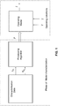
- the method further provides for processing the aforesaid characterization data to determine a plurality of parameters P of an operating model of the battery pack or cell, as a function of temperature and state of charge SOC of the battery pack or cell.
- the method provides for measuring an operating voltage V of the battery pack or cell and an operating temperature T, and estimating the operating current I of the battery pack or cell, by means of the aforesaid operating model, based on the measured operating voltage V, on the measured operating temperature T and on the aforesaid plurality of parameters P (as previously determined as a function of temperature and state of charge of the battery pack or cell).
- the operating current I is the instantaneous current flowing in the battery pack or cell when the instantaneous operating voltage of the battery or cell V and the instantaneous temperature T are detected. Such operating current I is therefore estimated based on the aforesaid parameters T, V and P.
- the parameters P are, in turn, obtained by means of a further processing, based on the temperature and the state of charge SOC of the battery pack or cell, as already noted above and as detailed below.
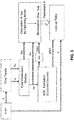
- the processing step comprises some stages, performed for each value of the aforesaid plurality of characterization temperature values T k .
- the processing step includes identifying a plurality of time observation windows W i along the respective time trends of the characterization voltage Vm and of the characterization current Im, associated with the characterization temperature T k , and detecting the respective characterization current Im i and characterization voltage Vm i values.
- the method provides for calculating a respective value of the state of charge SOC i of the battery pack or cell.
- the method provides for calculating a respective estimated voltage V ABi , by means of the operating model of the battery pack or cell, as a function of respective nominal values of the parameters P, and determining a respective error function E i dependent on the difference between the estimated voltage V ABi and the characterization voltage Vm i of the time observation window W i .
- the method provides for calculating an actual value P i for each of the plurality of parameters P of the model of the battery pack or cell, by minimizing the aforesaid error function E i .
- the step of associating the actual values P i of the parameters, calculated at the observation windows W i , with the respective state of charge SOC i and characterization temperature T k , is provided for, to obtain the aforesaid plurality of parameters P as a function of temperature and state of charge SOC of the battery pack or cell.
- the aforesaid step of processing the characterization data further provides for determining a respective of no-load voltage Voc i value of the battery pack or cell, at each observation window W i , and for defining a relationship between no-load voltage Voc and state of charge SOC of the battery pack or cell, based on the plurality of no-load voltages Voc i and state of charge SOC i values obtained at the observation windows W i .
- the step of calculating the actual value P i of the parameters also takes into account the respective no-load voltage Voc i value and the relationship which has been determined between no-load voltage Voc and state of charge SOC of the battery pack or cell.
- the step of identifying a plurality of observation windows W i comprises identifying time windows where the characterization current Im is zero, upon the exhaustion of transient phenomena, and where, consequently, the no-load voltage Voc i corresponds to the characterization voltage Vm i .
- the step of calculating a value of the state of charge of the battery pack or cell comprises calculating the respective value of the state of charge (SOC i ) of the battery pack or cell based on the time trend of the characterization current.
- the operating model of the battery pack or cell is an electric circuit model.
- the model parameters comprise electric circuit parameters.
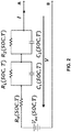
- the electric circuit model of the battery pack or cell comprises a no-load voltage Voc generator and a battery or cell internal resistance R 0 arranged in series with one or more circuit groups, each comprising the parallel of a circuit group resistance and of a circuit group capacity.
- the group of circuit parameters P comprises no-load voltage Voc, battery or cell internal resistance R 0 , one or more circuit group resistances R 1 , R 2 , and one or more circuit group capacities C 1 , C 2 .
- the example of Figure 2 shows a second order model (typically used to have an accurate and, at the same time, relatively simple modeling), i.e., a model comprising two circuit groups.
- the group of circuit parameters P comprises a first circuit group resistance R 1 , a first circuit group capacity C 1 , a second circuit group resistance R 2 , a second circuit group capacity C 2 , in addition to the battery or cell internal resistance R 0 and the no-load voltage Voc.
- the method may provide for the use of other types of models, even non-circuit models, characterized by a certain number of parameters, even non-circuit parameters.
- the operating model of the battery pack or cell comprises a trained predictive algorithm
- the parameters P are parameters of the trained predictive algorithm.
- the step of determining the plurality of parameters P comprises training the predictive algorithm according to the acquired battery pack or cell characterization data.
- a neural network with N parameters may be used.
- model parameters (Voc, R 0 , R 1 , R 2 , C 1 , C 2 ) are functions of the state of charge SOC and of the temperature.
- V AB t V OC ⁇ R 0 ⁇ I t ⁇ R 1 ⁇ I t ⁇ d C 1 ⁇ V 1 dt ⁇ R 2 ⁇ I t ⁇ d C 2 ⁇ V 2 dt in which the voltage V AB (t) represents the voltage at the terminals of the battery cell or cell and I(t) is the electric current circulating in the cell.
- the electric parameters depend on the temperature, and further depend, especially the no-load voltage Voc, on the state of charge of the battery cell or cell.
- the step of processing the characterization data is provided for, already described above in general terms.
- K time trends i.e., voltage and current trends, corresponding to K different predefined and set temperatures.
- T k T 1
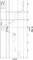
- the voltage and current time trends, acquired on the battery or cell at a temperature T 1 are selected.
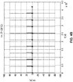
- time observation windows W i are identified in which the current is zero and remains at a zero value for a time interval such as to allow to consider as concluded the dynamics of the cell itself, i.e., in a condition in which the capacities C 1 and C 2 of the circuit model have been significantly discharged.
- the ends of the observation windows W i are indicated by "X" marks.
- the next stage is to calculate the state of charge (SOC) based on the measured current Im.
- SOC state of charge
- the state of charge SOC may be calculated, for example, by means of the so-called "Coulomb Counter” technique, based on the following formula [4]:
- SOC t SOC t 0 ⁇ 100 ⁇ t 0 t i ⁇ Q nom 3600 d ⁇
- Q nom is the nominal capacity of the cell (which, in the example shown, has a value of 20 Ah) evaluated at a discharge rate of 1 Coulomb.
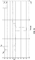
- the state of charge SOC calculated as a function of time, is shown in Figure 6 .
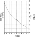
- the no-load voltage Voc is also calculated as a function of time.
- the initial and final points of the observation windows W i are "stationary" points, where the current is zero and therefore the voltage at the ends of the capacities C 1 and C 2 may be considered negligible. Therefore, at such points, the no-load voltage Voc coincides with the measured voltage Vm.
- the calculation of the no-load voltage Voc may be performed as a linear interpolation of the function of the previously estimated state of charge SOC.
- the no-load voltage Voc calculated as a function of time is shown in Figure 7 .
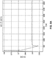
- Voc f -1 (SOC), the diagram of which is shown in Figure 9 .
- V OCi SOC i ⁇ SOC 2 ⁇ V OC 2 ⁇ V OC 1 SOC 2 ⁇ SOC 1 + V OC 2 in which the subscripts 1 and 2 respectively indicate the initial and final point of the observation window.
- ⁇ SOC SOC 2 - SOC 1 is, the more accurate is such approximate relationship.
- the estimated voltage V AB replicates with a high degree of precision the measured characterization voltage Vm, as shown in Figure 10 (in which, at the diagram scale, the two voltages are practically indistinguishable).
- the processing procedure is iterated for a plurality of characterization temperatures T k : ideally, the procedure may be performed for any number of temperature values.
- the value of each of the circuit parameters of the model of the battery pack or cell is available as a function of the value of the state of charge SOC and as a function of different operating temperature values.
- the results of the processing procedure may be collected and stored in the form of "look-up tables".
- the processing further comprises the step of storing, on electronic storage means (accessible to the battery pack or cell under operating conditions), the parameters P of the operating model of the battery pack or cell as look-up tables adapted to receive, as input, temperature and state of charge values, and to provide, as output, the respective values of parameters P.
- the step of estimating the operating current of the battery pack or cell is performed by means of an electronic processor associated with the battery pack or cell, adapted to access the aforesaid stored look-up tables and configured to receive, as input, measured operating voltage V and operating temperature T values originating from respective sensors embedded in the battery pack or cell.
- the step of acquiring characterization data of the battery pack or cell must be understood, in a broad sense, as making such data available, following a pre-characterization phase which may be performed in many different ways, including those described in the embodiments set forth here below, by way of non-limiting example.
- the step of acquiring characterization data of the battery pack or cell comprises measuring, before using the battery pack or cell under operating conditions, the time trends of the characterization voltage Vm and of the characterization current Im of the battery pack or cell, at the respective characterization temperature T k value.
- the step of acquiring characterization data of the battery pack or cell comprises acquiring characterization data from characterization procedures performed prior to the use under operating conditions of the battery pack or cell.
- the step of acquiring characterization data comprises deriving the characterization data from the available data sheets of the battery pack or cell.
- I R 1 T s ⁇ I old + C 1 ⁇ R 1 ⁇ I R 1 old T s + C 1 ⁇ C 1 old ⁇ R 1 + R 1 ⁇ R 1 old ⁇ C 1 + C 1 ⁇ R 1
- I R 2 T s ⁇ I old + C 2 ⁇ R 2 ⁇ I R 2 old T s + C 2 ⁇ C 2 old ⁇ R 2 + R 2 ⁇ R 2 old ⁇ C 2 + C 2 ⁇ R 2 in which, with the subscript OLD , the values of I, I R1 , I R2 , C 1 , C 2 , R 1 and R 2 obtained from the previous stage T S of the iteration are indicated.
- the previously described embodiments of the method allow to take into account, in an appropriate manner, the state of charge of the battery pack or cell and the operating temperature, so as to obtain reliable estimates of the battery pack or cell current, in any operating condition, and without need to detect such current directly.
- a further cause of deviation of the estimate from the actual value of the current may derive from the degradation and/or aging of the battery or cell and the components thereof.
- the parameters of the circuit model are valid when the battery or cell is new or at the time when the characterization is carried out.
- the dependence of such parameters on the state of charge and the temperature changes over time due to the degradation of the battery or cell. Therefore, strictly speaking, the characterization should be performed periodically, but this is not easy, or even not feasible, after the battery pack or cell has been mounted inside a hybrid or electric vehicle.
- a further embodiment of the method provides for the following further steps.
- a thermal model of the battery pack or cell is defined, in addition to the aforementioned operating model.
- the dissipated electric power P e is estimated by means of the operating model of the battery pack or cell, based on the values, measured in such interval (t 0 - t 1 ) of the voltage V and temperature T c of the battery pack or battery cell, and based on the parameters P estimated at the aforesaid temperature T c of the battery pack or battery cell.
- the dissipated thermal power P d is estimated by means of the thermal model of the battery pack or cell, based on the aforesaid value of the temperature T c of the battery pack or battery cell and based on an ambient temperature T e value, measured in such interval (t 0 - t 1 ) and based on the parameters P estimated at the temperature T c of the battery pack or battery cell.
- the step is then carried out to determine a difference ⁇ P between the dissipated electric power P e and the dissipated thermal power P d previously estimated.
- the parameters P are corrected based on the aforesaid estimated difference ⁇ P, so as to obtain updated values of the parameters P, such to take into account degradation and/or aging phenomena.
- a thermal model of the battery pack or cell consisting of one or more thermal cell models, in which each thermal cell model is characterized by a thermal cell capacity C T , a thermal cell resistance R T , a cell temperature T C and an ambient temperature T e .
- thermal cell capacity C T and thermal cell resistance R T parameters are specific to the cell and to the particular configuration of the battery pack or cell.
- thermal model used in the method is a first order thermal model, such as the one diagrammatically shown in Figure 12 .
- the value of the parameters can be updated.
- the aforesaid step of correcting the model parameters comprises the correction of the internal resistance R 0 parameter starting from the value determined in the absence of degradation, as previously described.
- a correction factor G is determined, based on the difference ⁇ P between the estimated electric power and the estimated thermal power; then, the battery or cell internal resistance R 0 value, valid in the absence of degradation, is multiplied by the aforesaid correction factor G to obtain an updated estimate of the battery or cell internal resistance R 0 .
- the step of recalculating the electric power P e based on the updated estimate of the internal resistance R 0 and then of iterating the aforesaid steps of determining, multiplying and recalculating, until the difference ⁇ P is reduced below a predetermined threshold.
- the updated estimate obtained at the end of the aforesaid iteration is considered as the internal resistance R 0 value of the battery or cell.
- An alternative embodiment of the method also aimed at estimating the electric operating parameters of the battery or cell in the presence of degradation and/or aging, comprises the steps of characterizing, before using the battery pack or cell under operating conditions, the change of the value of the internal resistance R 0 of the battery or cell as a function of the time of use and for different temperature values, and of storing the characterization data of the internal resistance of the battery or cell.
- a corrected value of the internal resistance R 0 of the battery or cell is used, according to the aforesaid characterization data of the internal resistance R 0 of the battery or cell, taking into account the elapsed time of actual use of the battery pack or cell.
- the present invention also comprises a method for estimating the state of charge SOC of a battery pack or cell.
- Such method comprises the steps of estimating the operating current I dispensed by a battery pack or cell, along an operating time of the battery pack or cell, according to any one of the embodiments described above. Then, the method provides for estimating the state of charge SOC of the battery pack or cell from an initial state of charge SOC 0 , based on the estimated time trend of the operating current I, starting from an operation start-up instant of the battery pack or cell up to a present instant.
- Such method allows for an accurate estimate of the state of charge, with an error equal to or lower than 3%, as shown by way of example in Figure 14 , in which a comparison is made between the state of charge SOC Imis estimated by measuring the current acquired by means of a physical sensor and the state of charge SOC Iest estimated based on this method, in the absence of a physical current sensor.
- the present invention further comprises a battery pack or cell control device configured to control the battery pack or cell even in the absence of an integrated current sensor, the device being adapted to receive a measured operating voltage V value of the battery pack or cell and a measured operating temperature T value of the battery pack or cell.
- the device comprises electronic processing means configured to perform a method for estimating the operating current I of the battery pack or cell, according to any of the embodiments described above, and/or to perform a method for estimating the state of charge SOC of the battery pack or cell according to any one of the embodiments described above.
- the present invention further comprises a battery pack or cell configured to operate without being equipped with integrated current sensors.
- the battery pack or cell comprises a voltage sensor, configured to detect an operating voltage V of the battery pack or cell; a temperature sensor, configured to detect an operating temperature T of the battery pack or cell; a control device according to what has been previously described.
- the object of the present invention is fully achieved by the estimation methods described, by virtue of the respective operating features thereof.
- the methods for estimating the current of the battery or cell and the state of charge of the battery or cell are based on a "on-line" acquisition (i.e., while the battery or cell is under operating conditions) of the voltage of the battery or cell and the temperature only, without requiring the direct acquisition of the current of the battery or cell by means of appropriate sensors.
- the methods for estimating the current of the battery or cell and the state of charge of the battery or cell allow to obtain estimates sufficiently accurate so as to be practically used effectively: in particular, the methods described allow to estimate the instantaneous current flowing through the battery pack or cell with an error lower than 5%, and to estimate the state of charge with an error lower than 3%.
Landscapes
- Physics & Mathematics (AREA)
- General Physics & Mathematics (AREA)
- Secondary Cells (AREA)
- Engineering & Computer Science (AREA)
- Power Engineering (AREA)
- Measurement Of Current Or Voltage (AREA)
- Tests Of Electric Status Of Batteries (AREA)
- Charge And Discharge Circuits For Batteries Or The Like (AREA)
Applications Claiming Priority (1)
| Application Number | Priority Date | Filing Date | Title |
|---|---|---|---|
| IT102017000058171A IT201700058171A1 (it) | 2017-05-29 | 2017-05-29 | Metodo di stima della corrente e dello stato di carica di un pacco batteria o cella, senza rilevazione diretta di corrente in condizioni operative |
Publications (2)
| Publication Number | Publication Date |
|---|---|
| EP3410139A1 EP3410139A1 (en) | 2018-12-05 |
| EP3410139B1 true EP3410139B1 (en) | 2019-12-11 |
Family
ID=60294052
Family Applications (1)
| Application Number | Title | Priority Date | Filing Date |
|---|---|---|---|
| EP18173905.3A Active EP3410139B1 (en) | 2017-05-29 | 2018-05-23 | Method for estimating the current and the state of charge of a battery pack or cell, without direct detection of current under operating conditions |
Country Status (5)
| Country | Link |
|---|---|
| US (1) | US10649035B2 (ja) |
| EP (1) | EP3410139B1 (ja) |
| JP (1) | JP7112252B2 (ja) |
| CN (1) | CN108931732B (ja) |
| IT (1) | IT201700058171A1 (ja) |
Families Citing this family (7)
| Publication number | Priority date | Publication date | Assignee | Title |
|---|---|---|---|---|
| CN114325395B (zh) * | 2020-09-30 | 2024-01-26 | 北京昇科能源科技有限责任公司 | 一种电池状态的确定方法及装置 |
| CN112462282B (zh) * | 2020-11-09 | 2022-03-18 | 西南大学 | 基于机理模型的用于确定电池组实时荷电状态的方法 |
| CN113748438B (zh) * | 2020-12-02 | 2023-09-05 | 宁德新能源科技有限公司 | 电量预测方法和设备 |
| CN113933725B (zh) * | 2021-09-08 | 2023-09-12 | 深圳大学 | 一种基于数据驱动确定动力电池荷电状态的方法 |
| CN113777505A (zh) * | 2021-09-13 | 2021-12-10 | 深圳创维汽车智能有限公司 | 一种显示屏电池的检测电路及方法 |
| CN113884884B (zh) * | 2021-10-21 | 2022-07-26 | 山东大学 | 一种基于相关性的动力电池组故障诊断方法及系统 |
| CN114264957B (zh) * | 2021-12-02 | 2024-05-07 | 东软集团股份有限公司 | 一种异常单体检测方法及其相关设备 |
Family Cites Families (11)
| Publication number | Priority date | Publication date | Assignee | Title |
|---|---|---|---|---|
| JP4767558B2 (ja) * | 2005-03-07 | 2011-09-07 | 日立ビークルエナジー株式会社 | 電源装置用状態検知装置,電源装置及び電源装置に用いられる初期特性抽出装置 |
| JP5029416B2 (ja) * | 2008-02-26 | 2012-09-19 | 日産自動車株式会社 | 二次電池の充電率推定装置および充電率推定方法 |
| US8242738B2 (en) * | 2008-05-28 | 2012-08-14 | Texas Instruments Incorporated | Systems and methods for determining battery parameters following active operation of the battery |
| US9678164B2 (en) * | 2010-03-23 | 2017-06-13 | Furukawa Electric Co., Ltd. | Battery internal state estimating apparatus and battery internal state estimating method |
| US9201121B2 (en) * | 2010-12-06 | 2015-12-01 | Texas Instruments Incorporated | System and method for sensing battery capacity |
| JP6033155B2 (ja) * | 2013-03-29 | 2016-11-30 | 日立オートモティブシステムズ株式会社 | 電池制御装置 |
| JP6129306B2 (ja) * | 2013-05-23 | 2017-05-17 | 日立オートモティブシステムズ株式会社 | 電池制御装置 |
| CN103744030B (zh) * | 2014-01-12 | 2016-06-01 | 中国科学院电工研究所 | 电池组健康状态和荷电状态在线估算装置及估算方法 |
| WO2015188610A1 (zh) * | 2014-06-11 | 2015-12-17 | 北京交通大学 | 电池荷电状态估算方法和装置 |
| US9891285B2 (en) * | 2014-10-29 | 2018-02-13 | Texas Instruments Incorporated | Battery fuel gauge |
| KR102399722B1 (ko) * | 2014-12-29 | 2022-05-19 | 삼성전자주식회사 | 전류 추정 방법 및 장치 |
-
2017
- 2017-05-29 IT IT102017000058171A patent/IT201700058171A1/it unknown
-
2018
- 2018-05-22 US US15/985,926 patent/US10649035B2/en active Active
- 2018-05-23 EP EP18173905.3A patent/EP3410139B1/en active Active
- 2018-05-25 JP JP2018100345A patent/JP7112252B2/ja active Active
- 2018-05-29 CN CN201810535539.5A patent/CN108931732B/zh not_active Expired - Fee Related
Non-Patent Citations (1)
| Title |
|---|
| None * |
Also Published As
| Publication number | Publication date |
|---|---|
| CN108931732A (zh) | 2018-12-04 |
| JP2019032299A (ja) | 2019-02-28 |
| US20180340981A1 (en) | 2018-11-29 |
| CN108931732B (zh) | 2022-06-17 |
| JP7112252B2 (ja) | 2022-08-03 |
| EP3410139A1 (en) | 2018-12-05 |
| US10649035B2 (en) | 2020-05-12 |
| IT201700058171A1 (it) | 2018-11-29 |
Similar Documents
| Publication | Publication Date | Title |
|---|---|---|
| EP3410139B1 (en) | Method for estimating the current and the state of charge of a battery pack or cell, without direct detection of current under operating conditions | |
| EP1873542B1 (en) | Apparatus and method for estimating charge of a battery | |
| EP2700964B1 (en) | Battery state estimation system, battery control system, battery system, and battery state estimation method | |
| JP5058814B2 (ja) | バッテリーの状態及びパラメーターの推定システム及び方法 | |
| JP3873623B2 (ja) | 電池充電状態の推定手段及び電池劣化状態推定方法 | |
| JP5944291B2 (ja) | バッテリのパラメータ等推定装置およびその推定方法 | |
| EP1688754B1 (en) | Battery management apparatus | |
| EP2565660A1 (en) | Degradation estimation device and degradation estimation method for storage battery device | |
| EP1707974B1 (en) | Remaining capacity calculating device and method for electric power storage | |
| JP5442583B2 (ja) | 電源装置用状態検知装置及び電源装置 | |
| EP2321663B1 (en) | Apparatus and method for estimating state of health of battery based on battery voltage variation pattern | |
| JP5329500B2 (ja) | バッテリの充電率推定装置 | |
| JP2018147680A (ja) | 温度異常判定装置、温度異常判定方法及びコンピュータプログラム | |
| EP3593156A2 (en) | A battery state of power estimation method and a battery state monitoring system | |
| JP2018129130A (ja) | 電池温度推定装置、電池温度推定方法及びコンピュータプログラム | |
| JP4509670B2 (ja) | 蓄電デバイスの残存容量演算装置 | |
| JP4519523B2 (ja) | 蓄電デバイスの残存容量演算装置 | |
| JP4509674B2 (ja) | 蓄電デバイスの残存容量演算装置 | |
| EP3015835B1 (en) | A method and a system for determining the operating temperature of a cell of an electric charge accumulator assembly without physical temperature sensors, particularly for electric or hybrid motor vehicles | |
| JP7377743B2 (ja) | バッテリ管理装置 | |
| JP2018096954A (ja) | 電池状態推定装置 | |
| JP2022179322A (ja) | 電池システムおよび組電池の制御方法 | |
| CN114460479A (zh) | 一种电池荷电状态检测方法、装置及介质 |
Legal Events
| Date | Code | Title | Description |
|---|---|---|---|
| PUAI | Public reference made under article 153(3) epc to a published international application that has entered the european phase |
Free format text: ORIGINAL CODE: 0009012 |
|
| STAA | Information on the status of an ep patent application or granted ep patent |
Free format text: STATUS: THE APPLICATION HAS BEEN PUBLISHED |
|
| AK | Designated contracting states |
Kind code of ref document: A1 Designated state(s): AL AT BE BG CH CY CZ DE DK EE ES FI FR GB GR HR HU IE IS IT LI LT LU LV MC MK MT NL NO PL PT RO RS SE SI SK SM TR |
|
| AX | Request for extension of the european patent |
Extension state: BA ME |
|
| STAA | Information on the status of an ep patent application or granted ep patent |
Free format text: STATUS: REQUEST FOR EXAMINATION WAS MADE |
|
| REG | Reference to a national code |
Ref country code: DE Ref legal event code: R079 Ref document number: 602018001553 Country of ref document: DE Free format text: PREVIOUS MAIN CLASS: G01R0031360000 Ipc: G01R0031367000 |
|
| 17P | Request for examination filed |
Effective date: 20190524 |
|
| RBV | Designated contracting states (corrected) |
Designated state(s): AL AT BE BG CH CY CZ DE DK EE ES FI FR GB GR HR HU IE IS IT LI LT LU LV MC MK MT NL NO PL PT RO RS SE SI SK SM TR |
|
| GRAP | Despatch of communication of intention to grant a patent |
Free format text: ORIGINAL CODE: EPIDOSNIGR1 |
|
| STAA | Information on the status of an ep patent application or granted ep patent |
Free format text: STATUS: GRANT OF PATENT IS INTENDED |
|
| RIC1 | Information provided on ipc code assigned before grant |
Ipc: G01R 31/389 20190101ALN20190621BHEP Ipc: G01R 31/374 20190101ALI20190621BHEP Ipc: G01R 31/367 20190101AFI20190621BHEP Ipc: G01R 31/3835 20190101ALN20190621BHEP |
|
| INTG | Intention to grant announced |
Effective date: 20190709 |
|
| GRAS | Grant fee paid |
Free format text: ORIGINAL CODE: EPIDOSNIGR3 |
|
| GRAA | (expected) grant |
Free format text: ORIGINAL CODE: 0009210 |
|
| STAA | Information on the status of an ep patent application or granted ep patent |
Free format text: STATUS: THE PATENT HAS BEEN GRANTED |
|
| AK | Designated contracting states |
Kind code of ref document: B1 Designated state(s): AL AT BE BG CH CY CZ DE DK EE ES FI FR GB GR HR HU IE IS IT LI LT LU LV MC MK MT NL NO PL PT RO RS SE SI SK SM TR |
|
| REG | Reference to a national code |
Ref country code: GB Ref legal event code: FG4D |
|
| REG | Reference to a national code |
Ref country code: CH Ref legal event code: EP |
|
| REG | Reference to a national code |
Ref country code: AT Ref legal event code: REF Ref document number: 1212733 Country of ref document: AT Kind code of ref document: T Effective date: 20191215 |
|
| REG | Reference to a national code |
Ref country code: DE Ref legal event code: R096 Ref document number: 602018001553 Country of ref document: DE |
|
| REG | Reference to a national code |
Ref country code: IE Ref legal event code: FG4D |
|
| REG | Reference to a national code |
Ref country code: NL Ref legal event code: MP Effective date: 20191211 |
|
| REG | Reference to a national code |
Ref country code: LT Ref legal event code: MG4D |
|
| PG25 | Lapsed in a contracting state [announced via postgrant information from national office to epo] |
Ref country code: LT Free format text: LAPSE BECAUSE OF FAILURE TO SUBMIT A TRANSLATION OF THE DESCRIPTION OR TO PAY THE FEE WITHIN THE PRESCRIBED TIME-LIMIT Effective date: 20191211 Ref country code: NO Free format text: LAPSE BECAUSE OF FAILURE TO SUBMIT A TRANSLATION OF THE DESCRIPTION OR TO PAY THE FEE WITHIN THE PRESCRIBED TIME-LIMIT Effective date: 20200311 Ref country code: GR Free format text: LAPSE BECAUSE OF FAILURE TO SUBMIT A TRANSLATION OF THE DESCRIPTION OR TO PAY THE FEE WITHIN THE PRESCRIBED TIME-LIMIT Effective date: 20200312 Ref country code: LV Free format text: LAPSE BECAUSE OF FAILURE TO SUBMIT A TRANSLATION OF THE DESCRIPTION OR TO PAY THE FEE WITHIN THE PRESCRIBED TIME-LIMIT Effective date: 20191211 Ref country code: SE Free format text: LAPSE BECAUSE OF FAILURE TO SUBMIT A TRANSLATION OF THE DESCRIPTION OR TO PAY THE FEE WITHIN THE PRESCRIBED TIME-LIMIT Effective date: 20191211 Ref country code: FI Free format text: LAPSE BECAUSE OF FAILURE TO SUBMIT A TRANSLATION OF THE DESCRIPTION OR TO PAY THE FEE WITHIN THE PRESCRIBED TIME-LIMIT Effective date: 20191211 Ref country code: BG Free format text: LAPSE BECAUSE OF FAILURE TO SUBMIT A TRANSLATION OF THE DESCRIPTION OR TO PAY THE FEE WITHIN THE PRESCRIBED TIME-LIMIT Effective date: 20200311 |
|
| PG25 | Lapsed in a contracting state [announced via postgrant information from national office to epo] |
Ref country code: HR Free format text: LAPSE BECAUSE OF FAILURE TO SUBMIT A TRANSLATION OF THE DESCRIPTION OR TO PAY THE FEE WITHIN THE PRESCRIBED TIME-LIMIT Effective date: 20191211 Ref country code: RS Free format text: LAPSE BECAUSE OF FAILURE TO SUBMIT A TRANSLATION OF THE DESCRIPTION OR TO PAY THE FEE WITHIN THE PRESCRIBED TIME-LIMIT Effective date: 20191211 |
|
| PG25 | Lapsed in a contracting state [announced via postgrant information from national office to epo] |
Ref country code: AL Free format text: LAPSE BECAUSE OF FAILURE TO SUBMIT A TRANSLATION OF THE DESCRIPTION OR TO PAY THE FEE WITHIN THE PRESCRIBED TIME-LIMIT Effective date: 20191211 |
|
| PG25 | Lapsed in a contracting state [announced via postgrant information from national office to epo] |
Ref country code: PT Free format text: LAPSE BECAUSE OF FAILURE TO SUBMIT A TRANSLATION OF THE DESCRIPTION OR TO PAY THE FEE WITHIN THE PRESCRIBED TIME-LIMIT Effective date: 20200506 Ref country code: EE Free format text: LAPSE BECAUSE OF FAILURE TO SUBMIT A TRANSLATION OF THE DESCRIPTION OR TO PAY THE FEE WITHIN THE PRESCRIBED TIME-LIMIT Effective date: 20191211 Ref country code: ES Free format text: LAPSE BECAUSE OF FAILURE TO SUBMIT A TRANSLATION OF THE DESCRIPTION OR TO PAY THE FEE WITHIN THE PRESCRIBED TIME-LIMIT Effective date: 20191211 Ref country code: NL Free format text: LAPSE BECAUSE OF FAILURE TO SUBMIT A TRANSLATION OF THE DESCRIPTION OR TO PAY THE FEE WITHIN THE PRESCRIBED TIME-LIMIT Effective date: 20191211 Ref country code: CZ Free format text: LAPSE BECAUSE OF FAILURE TO SUBMIT A TRANSLATION OF THE DESCRIPTION OR TO PAY THE FEE WITHIN THE PRESCRIBED TIME-LIMIT Effective date: 20191211 Ref country code: RO Free format text: LAPSE BECAUSE OF FAILURE TO SUBMIT A TRANSLATION OF THE DESCRIPTION OR TO PAY THE FEE WITHIN THE PRESCRIBED TIME-LIMIT Effective date: 20191211 |
|
| PG25 | Lapsed in a contracting state [announced via postgrant information from national office to epo] |
Ref country code: SM Free format text: LAPSE BECAUSE OF FAILURE TO SUBMIT A TRANSLATION OF THE DESCRIPTION OR TO PAY THE FEE WITHIN THE PRESCRIBED TIME-LIMIT Effective date: 20191211 Ref country code: IS Free format text: LAPSE BECAUSE OF FAILURE TO SUBMIT A TRANSLATION OF THE DESCRIPTION OR TO PAY THE FEE WITHIN THE PRESCRIBED TIME-LIMIT Effective date: 20200411 Ref country code: SK Free format text: LAPSE BECAUSE OF FAILURE TO SUBMIT A TRANSLATION OF THE DESCRIPTION OR TO PAY THE FEE WITHIN THE PRESCRIBED TIME-LIMIT Effective date: 20191211 |
|
| REG | Reference to a national code |
Ref country code: DE Ref legal event code: R097 Ref document number: 602018001553 Country of ref document: DE |
|
| REG | Reference to a national code |
Ref country code: AT Ref legal event code: MK05 Ref document number: 1212733 Country of ref document: AT Kind code of ref document: T Effective date: 20191211 |
|
| PLBE | No opposition filed within time limit |
Free format text: ORIGINAL CODE: 0009261 |
|
| STAA | Information on the status of an ep patent application or granted ep patent |
Free format text: STATUS: NO OPPOSITION FILED WITHIN TIME LIMIT |
|
| PG25 | Lapsed in a contracting state [announced via postgrant information from national office to epo] |
Ref country code: DK Free format text: LAPSE BECAUSE OF FAILURE TO SUBMIT A TRANSLATION OF THE DESCRIPTION OR TO PAY THE FEE WITHIN THE PRESCRIBED TIME-LIMIT Effective date: 20191211 |
|
| 26N | No opposition filed |
Effective date: 20200914 |
|
| PG25 | Lapsed in a contracting state [announced via postgrant information from national office to epo] |
Ref country code: SI Free format text: LAPSE BECAUSE OF FAILURE TO SUBMIT A TRANSLATION OF THE DESCRIPTION OR TO PAY THE FEE WITHIN THE PRESCRIBED TIME-LIMIT Effective date: 20191211 Ref country code: AT Free format text: LAPSE BECAUSE OF FAILURE TO SUBMIT A TRANSLATION OF THE DESCRIPTION OR TO PAY THE FEE WITHIN THE PRESCRIBED TIME-LIMIT Effective date: 20191211 |
|
| PG25 | Lapsed in a contracting state [announced via postgrant information from national office to epo] |
Ref country code: MC Free format text: LAPSE BECAUSE OF FAILURE TO SUBMIT A TRANSLATION OF THE DESCRIPTION OR TO PAY THE FEE WITHIN THE PRESCRIBED TIME-LIMIT Effective date: 20191211 |
|
| PG25 | Lapsed in a contracting state [announced via postgrant information from national office to epo] |
Ref country code: PL Free format text: LAPSE BECAUSE OF FAILURE TO SUBMIT A TRANSLATION OF THE DESCRIPTION OR TO PAY THE FEE WITHIN THE PRESCRIBED TIME-LIMIT Effective date: 20191211 |
|
| REG | Reference to a national code |
Ref country code: BE Ref legal event code: MM Effective date: 20200531 |
|
| PG25 | Lapsed in a contracting state [announced via postgrant information from national office to epo] |
Ref country code: LU Free format text: LAPSE BECAUSE OF NON-PAYMENT OF DUE FEES Effective date: 20200523 |
|
| PG25 | Lapsed in a contracting state [announced via postgrant information from national office to epo] |
Ref country code: IE Free format text: LAPSE BECAUSE OF NON-PAYMENT OF DUE FEES Effective date: 20200523 |
|
| PG25 | Lapsed in a contracting state [announced via postgrant information from national office to epo] |
Ref country code: BE Free format text: LAPSE BECAUSE OF NON-PAYMENT OF DUE FEES Effective date: 20200531 |
|
| REG | Reference to a national code |
Ref country code: CH Ref legal event code: PL |
|
| PG25 | Lapsed in a contracting state [announced via postgrant information from national office to epo] |
Ref country code: LI Free format text: LAPSE BECAUSE OF NON-PAYMENT OF DUE FEES Effective date: 20210531 Ref country code: CH Free format text: LAPSE BECAUSE OF NON-PAYMENT OF DUE FEES Effective date: 20210531 |
|
| PG25 | Lapsed in a contracting state [announced via postgrant information from national office to epo] |
Ref country code: TR Free format text: LAPSE BECAUSE OF FAILURE TO SUBMIT A TRANSLATION OF THE DESCRIPTION OR TO PAY THE FEE WITHIN THE PRESCRIBED TIME-LIMIT Effective date: 20191211 Ref country code: MT Free format text: LAPSE BECAUSE OF FAILURE TO SUBMIT A TRANSLATION OF THE DESCRIPTION OR TO PAY THE FEE WITHIN THE PRESCRIBED TIME-LIMIT Effective date: 20191211 Ref country code: CY Free format text: LAPSE BECAUSE OF FAILURE TO SUBMIT A TRANSLATION OF THE DESCRIPTION OR TO PAY THE FEE WITHIN THE PRESCRIBED TIME-LIMIT Effective date: 20191211 |
|
| PG25 | Lapsed in a contracting state [announced via postgrant information from national office to epo] |
Ref country code: MK Free format text: LAPSE BECAUSE OF FAILURE TO SUBMIT A TRANSLATION OF THE DESCRIPTION OR TO PAY THE FEE WITHIN THE PRESCRIBED TIME-LIMIT Effective date: 20191211 |
|
| PGFP | Annual fee paid to national office [announced via postgrant information from national office to epo] |
Ref country code: IT Payment date: 20220421 Year of fee payment: 5 Ref country code: FR Payment date: 20220421 Year of fee payment: 5 Ref country code: DE Payment date: 20220420 Year of fee payment: 5 |
|
| GBPC | Gb: european patent ceased through non-payment of renewal fee |
Effective date: 20220523 |
|
| PG25 | Lapsed in a contracting state [announced via postgrant information from national office to epo] |
Ref country code: GB Free format text: LAPSE BECAUSE OF NON-PAYMENT OF DUE FEES Effective date: 20220523 |
|
| REG | Reference to a national code |
Ref country code: DE Ref legal event code: R119 Ref document number: 602018001553 Country of ref document: DE |
|
| PG25 | Lapsed in a contracting state [announced via postgrant information from national office to epo] |
Ref country code: IT Free format text: LAPSE BECAUSE OF NON-PAYMENT OF DUE FEES Effective date: 20230523 Ref country code: DE Free format text: LAPSE BECAUSE OF NON-PAYMENT OF DUE FEES Effective date: 20231201 |