EP3410057B1 - Drone-based active protection system - Google Patents
Drone-based active protection system Download PDFInfo
- Publication number
- EP3410057B1 EP3410057B1 EP18174698.3A EP18174698A EP3410057B1 EP 3410057 B1 EP3410057 B1 EP 3410057B1 EP 18174698 A EP18174698 A EP 18174698A EP 3410057 B1 EP3410057 B1 EP 3410057B1
- Authority
- EP
- European Patent Office
- Prior art keywords
- uav
- threat
- platform
- vehicle
- target
- Prior art date
- Legal status (The legal status is an assumption and is not a legal conclusion. Google has not performed a legal analysis and makes no representation as to the accuracy of the status listed.)
- Active
Links
- 238000012545 processing Methods 0.000 claims description 11
- 230000003472 neutralizing effect Effects 0.000 claims description 10
- 238000001514 detection method Methods 0.000 claims description 9
- 238000009434 installation Methods 0.000 claims description 3
- 238000010801 machine learning Methods 0.000 claims description 3
- 230000000670 limiting effect Effects 0.000 description 13
- 238000000034 method Methods 0.000 description 9
- 238000006386 neutralization reaction Methods 0.000 description 8
- 230000006378 damage Effects 0.000 description 6
- 238000004891 communication Methods 0.000 description 4
- 230000004913 activation Effects 0.000 description 3
- 230000005540 biological transmission Effects 0.000 description 3
- 230000006870 function Effects 0.000 description 3
- 230000033001 locomotion Effects 0.000 description 3
- 239000000463 material Substances 0.000 description 3
- 238000012986 modification Methods 0.000 description 3
- 230000004048 modification Effects 0.000 description 3
- 230000003213 activating effect Effects 0.000 description 2
- 230000000694 effects Effects 0.000 description 2
- 238000004880 explosion Methods 0.000 description 2
- 230000003116 impacting effect Effects 0.000 description 2
- 230000003287 optical effect Effects 0.000 description 2
- 230000002829 reductive effect Effects 0.000 description 2
- 235000015842 Hesperis Nutrition 0.000 description 1
- 235000012633 Iberis amara Nutrition 0.000 description 1
- 238000004364 calculation method Methods 0.000 description 1
- 230000017525 heat dissipation Effects 0.000 description 1
- 238000010348 incorporation Methods 0.000 description 1
- 230000002401 inhibitory effect Effects 0.000 description 1
- 230000010354 integration Effects 0.000 description 1
- 230000006855 networking Effects 0.000 description 1
- 238000005457 optimization Methods 0.000 description 1
- 239000008188 pellet Substances 0.000 description 1
- 230000000704 physical effect Effects 0.000 description 1
- 230000001681 protective effect Effects 0.000 description 1
- 230000005855 radiation Effects 0.000 description 1
- 230000036962 time dependent Effects 0.000 description 1
- 238000012795 verification Methods 0.000 description 1
Images
Classifications
-
- G—PHYSICS
- G05—CONTROLLING; REGULATING
- G05D—SYSTEMS FOR CONTROLLING OR REGULATING NON-ELECTRIC VARIABLES
- G05D1/00—Control of position, course or altitude of land, water, air, or space vehicles, e.g. automatic pilot
- G05D1/0094—Control of position, course or altitude of land, water, air, or space vehicles, e.g. automatic pilot involving pointing a payload, e.g. camera, weapon, sensor, towards a fixed or moving target
-
- B—PERFORMING OPERATIONS; TRANSPORTING
- B64—AIRCRAFT; AVIATION; COSMONAUTICS
- B64C—AEROPLANES; HELICOPTERS
- B64C39/00—Aircraft not otherwise provided for
- B64C39/02—Aircraft not otherwise provided for characterised by special use
- B64C39/024—Aircraft not otherwise provided for characterised by special use of the remote controlled vehicle type, i.e. RPV
-
- F—MECHANICAL ENGINEERING; LIGHTING; HEATING; WEAPONS; BLASTING
- F41—WEAPONS
- F41H—ARMOUR; ARMOURED TURRETS; ARMOURED OR ARMED VEHICLES; MEANS OF ATTACK OR DEFENCE, e.g. CAMOUFLAGE, IN GENERAL
- F41H11/00—Defence installations; Defence devices
-
- F—MECHANICAL ENGINEERING; LIGHTING; HEATING; WEAPONS; BLASTING
- F41—WEAPONS
- F41H—ARMOUR; ARMOURED TURRETS; ARMOURED OR ARMED VEHICLES; MEANS OF ATTACK OR DEFENCE, e.g. CAMOUFLAGE, IN GENERAL
- F41H13/00—Means of attack or defence not otherwise provided for
- F41H13/0043—Directed energy weapons, i.e. devices that direct a beam of high energy content toward a target for incapacitating or destroying the target
- F41H13/005—Directed energy weapons, i.e. devices that direct a beam of high energy content toward a target for incapacitating or destroying the target the high-energy beam being a laser beam
-
- F—MECHANICAL ENGINEERING; LIGHTING; HEATING; WEAPONS; BLASTING
- F41—WEAPONS
- F41H—ARMOUR; ARMOURED TURRETS; ARMOURED OR ARMED VEHICLES; MEANS OF ATTACK OR DEFENCE, e.g. CAMOUFLAGE, IN GENERAL
- F41H13/00—Means of attack or defence not otherwise provided for
- F41H13/0093—Devices generating an electromagnetic pulse, e.g. for disrupting or destroying electronic devices
-
- F—MECHANICAL ENGINEERING; LIGHTING; HEATING; WEAPONS; BLASTING
- F42—AMMUNITION; BLASTING
- F42B—EXPLOSIVE CHARGES, e.g. FOR BLASTING, FIREWORKS, AMMUNITION
- F42B12/00—Projectiles, missiles or mines characterised by the warhead, the intended effect, or the material
- F42B12/02—Projectiles, missiles or mines characterised by the warhead, the intended effect, or the material characterised by the warhead or the intended effect
- F42B12/36—Projectiles, missiles or mines characterised by the warhead, the intended effect, or the material characterised by the warhead or the intended effect for dispensing materials; for producing chemical or physical reaction; for signalling ; for transmitting information
- F42B12/56—Projectiles, missiles or mines characterised by the warhead, the intended effect, or the material characterised by the warhead or the intended effect for dispensing materials; for producing chemical or physical reaction; for signalling ; for transmitting information for dispensing discrete solid bodies
- F42B12/70—Projectiles, missiles or mines characterised by the warhead, the intended effect, or the material characterised by the warhead or the intended effect for dispensing materials; for producing chemical or physical reaction; for signalling ; for transmitting information for dispensing discrete solid bodies for dispensing radar chaff or infrared material
-
- G—PHYSICS
- G01—MEASURING; TESTING
- G01S—RADIO DIRECTION-FINDING; RADIO NAVIGATION; DETERMINING DISTANCE OR VELOCITY BY USE OF RADIO WAVES; LOCATING OR PRESENCE-DETECTING BY USE OF THE REFLECTION OR RERADIATION OF RADIO WAVES; ANALOGOUS ARRANGEMENTS USING OTHER WAVES
- G01S5/00—Position-fixing by co-ordinating two or more direction or position line determinations; Position-fixing by co-ordinating two or more distance determinations
- G01S5/0009—Transmission of position information to remote stations
- G01S5/0072—Transmission between mobile stations, e.g. anti-collision systems
-
- G—PHYSICS
- G01—MEASURING; TESTING
- G01S—RADIO DIRECTION-FINDING; RADIO NAVIGATION; DETERMINING DISTANCE OR VELOCITY BY USE OF RADIO WAVES; LOCATING OR PRESENCE-DETECTING BY USE OF THE REFLECTION OR RERADIATION OF RADIO WAVES; ANALOGOUS ARRANGEMENTS USING OTHER WAVES
- G01S7/00—Details of systems according to groups G01S13/00, G01S15/00, G01S17/00
- G01S7/02—Details of systems according to groups G01S13/00, G01S15/00, G01S17/00 of systems according to group G01S13/00
- G01S7/38—Jamming means, e.g. producing false echoes
-
- G—PHYSICS
- G05—CONTROLLING; REGULATING
- G05D—SYSTEMS FOR CONTROLLING OR REGULATING NON-ELECTRIC VARIABLES
- G05D1/00—Control of position, course or altitude of land, water, air, or space vehicles, e.g. automatic pilot
- G05D1/0088—Control of position, course or altitude of land, water, air, or space vehicles, e.g. automatic pilot characterized by the autonomous decision making process, e.g. artificial intelligence, predefined behaviours
-
- G—PHYSICS
- G05—CONTROLLING; REGULATING
- G05D—SYSTEMS FOR CONTROLLING OR REGULATING NON-ELECTRIC VARIABLES
- G05D1/00—Control of position, course or altitude of land, water, air, or space vehicles, e.g. automatic pilot
- G05D1/12—Target-seeking control
-
- B—PERFORMING OPERATIONS; TRANSPORTING
- B64—AIRCRAFT; AVIATION; COSMONAUTICS
- B64U—UNMANNED AERIAL VEHICLES [UAV]; EQUIPMENT THEREFOR
- B64U10/00—Type of UAV
- B64U10/10—Rotorcrafts
- B64U10/13—Flying platforms
- B64U10/14—Flying platforms with four distinct rotor axes, e.g. quadcopters
-
- B—PERFORMING OPERATIONS; TRANSPORTING
- B64—AIRCRAFT; AVIATION; COSMONAUTICS
- B64U—UNMANNED AERIAL VEHICLES [UAV]; EQUIPMENT THEREFOR
- B64U2101/00—UAVs specially adapted for particular uses or applications
- B64U2101/15—UAVs specially adapted for particular uses or applications for conventional or electronic warfare
-
- B—PERFORMING OPERATIONS; TRANSPORTING
- B64—AIRCRAFT; AVIATION; COSMONAUTICS
- B64U—UNMANNED AERIAL VEHICLES [UAV]; EQUIPMENT THEREFOR
- B64U2201/00—UAVs characterised by their flight controls
- B64U2201/10—UAVs characterised by their flight controls autonomous, i.e. by navigating independently from ground or air stations, e.g. by using inertial navigation systems [INS]
-
- B—PERFORMING OPERATIONS; TRANSPORTING
- B64—AIRCRAFT; AVIATION; COSMONAUTICS
- B64U—UNMANNED AERIAL VEHICLES [UAV]; EQUIPMENT THEREFOR
- B64U50/00—Propulsion; Power supply
- B64U50/30—Supply or distribution of electrical power
- B64U50/34—In-flight charging
- B64U50/35—In-flight charging by wireless transmission, e.g. by induction
Definitions
- the presently disclosed subject matter related to protection systems for vehicles and other targets, in particular to systems configured for facilitating deployment of active protection.
- Active protection systems are typically provided to neutralize incoming threats to a target, such as armored vehicles, by destroying or diverting it, or otherwise removing the danger posed thereby.
- Active protection systems generally fall into two broad categories - hard-kill countermeasures and soft-kill countermeasures.
- the former usually involves neutralizing the threat by impacting it by other materials such as a projectile, and the latter usually involves exploiting physical properties associated with or relied on for operation of the threat (e.g., electromagnetic, acoustic, or other signature) to neutralize it.
- the threat should be neutralized as far as is practical from the target.
- neutralization of the threat is accompanied by an explosion, which itself could damage the target if it occurs too closely thereto.
- a suitable distance is necessary to ensure that the neutralization properly occurs.
- US 2015/0276353 discloses an armored vehicle which includes a basic armored vehicle having a predetermined basic external armor, a modularized armor structure exchangeably attached to the basic external armor, and an unmanned aerial vehicle loaded on the modularized armor structure.
- the modularized armor structure includes an unmanned aerial vehicle loading section configured to load the unmanned aerial vehicle, an armoring material structure formed of armoring material, and an attaching section used to exchangeably attach the modularized armor structure to the basic armored vehicle.
- US 2005/0051667 discloses a flying micro-rotorcraft unit for remote tactical and operational missions.
- the unit includes an elongated body having an upper and a lower end. The body defines a vertical axis.
- the unit further includes a navigation module including means for determining a global position of the elongated body during flight of the unit.
- Rotor means of the unit is coupled to the upper end of the elongated body for generating a thrust force that acts in a direction parallel to the vertical axis to lift the elongated body into the air.
- the rotor means is located between the elongated body and the navigation module.
- EP 2 778 598 discloses a method performed by an apparatus comprising a first module and a second module.
- the first module is mounted on an unmanned vehicle and arranged to act upon a payload also mounted on the vehicle.
- the second module is remote from the unmanned vehicle.
- the method comprises receiving, by the second module, an instruction to activate the payload; generating, by the second module, a plurality of activation codes and sending those codes to the first module; determining, by the first module, whether or not each of the received activation codes is valid; and if the codes are valid, activating the pavload, or, if the codes are not valid, preventing activation of the payload.
- Each code comprises a time dependent portion, a single-use portion, and an identifier for the unmanned vehicle.
- US 2010/0042269 discloses a method of protecting an asset using at least one unmanned vehicle.
- the method includes establishing a plurality of boundaries around the asset. The boundaries define edges of zones.
- the method further includes observing a target in a first one of the zones.
- the method further includes deploying the unmanned vehicle to a location in a vicinity of the asset and tasking the vehicle to perform a first defensive measure as long as the target remains in the first zone. If the target crosses a boundary from the first zone into a second one of the zones, where the second zone is more proximate to the asset than the first zone, the method further includes tasking the vehicle to perform a second defensive measure.
- the invention is a system as defined by claim 1. According to one aspect of the presently disclosed subject matter, there is provided a system for facilitating active protection of a target from a threat, the system comprising:
- At least some of the UAV's may be configured to hover in a fixed location.
- At least some of the UAV's may be fixed-wing aircraft.
- At least some of the UAV's may each be connected to the platform and/or the target by a cable for being powered thereby.
- At least some of the UAV's may be configured to receive power from the platform and/or the target wirelessly.
- At least some of the UAV's may each comprise a battery.
- At least some of the UAV's may comprise surveillance equipment configured to facilitate detection of the threat.
- the UAV's may be configured for transmitting surveillance data to the platform, the platform being configured for processing the surveillance data to detect the threat.
- the surveillance equipment may comprise one or more selected from the group including an optical sensor, an infrared sensor, a motion sensor, a thermal sensor, and a pulse-Doppler radar.
- the platform may be configured to communicate with an active protection system for directing operation thereof.
- One or more of the UAV's may comprise the active protection system.
- the platform may comprise the active protection system.
- the active protection system may comprise one or more hard-kill countermeasures.
- the hard-kill countermeasures may be selected from the group including one or more projectiles and a laser weapon (i.e., configured to emit a beam of directed energy).
- One or more of the UAV's may be configured for intercepting the threat to neutralize it (i.e., the UAV itself constituting the hard-kill countermeasure).
- the active protection system may comprise one or more soft-kill countermeasures.
- the soft-kill countermeasures may be selected from the group including chaff, radar jamming, electromagnetic pulses, a laser dazzler, and a radio frequency decoy.
- Each of the UAV's may comprise a location sensor configured to determine the absolute location thereof.
- the system may be configured to determine the relative location of each of the UAV's with respect to the platform and/or other of the UAV's.
- the platform may be configured for installation on the target.
- the target may be a vehicle, for example an armored vehicle.
- the system may be configured to implement machine learning to improve performance of at least one task.
- a system which is generally indicated at 10.
- the system 10 is configured to facilitate active protection of a target such as a vehicle 12, which may be a tank, a personnel carrier, a marine vehicle, an airborne vehicle, etc., from an incoming threat.
- a target such as a vehicle 12, which may be a tank, a personnel carrier, a marine vehicle, an airborne vehicle, etc.
- the threats are rockets or missiles.
- references herein to the system 10 may, for the sake of clarity, include the vehicle as well, unless otherwise clear from context.
- References to facilitating protection from a threat may comprise some or all activities connected to an operation to neutralize a threat or to otherwise remove a target from being in danger therefrom, including, but not limited to, detecting the threat, destroying it, damaging it, diverting it, prematurely activating it, slowing it, etc.
- the system 10 comprises a plurality of unmanned aerial vehicles (UAVs) 14, and at least one central platform 16, configured for coordinating operation of the system.
- the platform 16 may be configured for installation on the vehicle 12, for example being provided as an independent unit, e.g., configured for mounting on the vehicle 12, or it may be configured for integration with an existing system, e.g., of the vehicle (for example, it may comprise software which is installed on an existing processing unit, e.g., the mission computer, of the vehicle; in such a case, the vehicle itself constitutes the platform of the system).
- the platform 16 may be configured for being separate and/or remote from the vehicle 12, for example in a separate vehicle configured to maintain a close proximity to the vehicle, or in a separate location altogether.
- the platform thus comprises a system controller, which may be a dedicated controller, or part of a controller of an external system, for example one associated with the vehicle 12.
- controller is used with reference to a single element, it may comprise a combination of elements, which may or may not be in physical proximity to one another, without departing from the scope of the presently disclosed subject matter, mutatis mutandis (i.e., the term controller is used as a logical description, not necessarily as a constructional description of a particular physical computing device).
- descriptions herein the specification and recitation in the appended claims of multiple controllers includes, and may be embodied in practice by, a single controller.
- platform 16 is described herein with reference to and illustrated in the accompanying drawings as being associated with the vehicle 12, it will be appreciated that it may be associated with a different vehicle, a stationary location, etc., without departing from the scope of the presently disclosed subject matter, mutatis mutandis. It will be further appreciated that the platform 16 may be provided, mutatis mutandis, such that it is adapted for use with a land vehicle, a marine vehicle, an airborne vehicle such as one of the UAV's 14, etc., without departing from the scope of the presently disclosed subject matter.
- the UAV's are configured to operate (i.e., physically fly during operation) in the vicinity of the vehicle 12, such that it may facilitate in rapidly detecting and/or neutralizing fast-moving threats, such as anti-tank missiles, etc.
- the vicinity may be considered to be within a distance which does not exceed that distance from which the threat is launched.
- the vicinity is within about 100 m (about 328 ft.). It will be appreciated that the specific distance may vary, for example exceeding about 100 m (about 328 ft.), but still being less than the distance from which the threat is launched.
- Each of the UAV's 14 may be associated with a UAV controller (not illustrated) for directing its operation, in particular the operation of its elements, as will be described below.
- the UAV controller is configured to communicate, directly and/or indirectly, with elements of the UAV 14, for example to receive information and/or data therefrom, and/or to direct operation thereof. It may comprise one or more communications modules to facilitate transmission/receipt of data between elements of the UAV 14, other UAV's, the platform 16 (e.g., the platform controller), and/or external systems, e.g., to be directly controlled thereby.
- the UAV controller may be provided as an element of the UAV 14 or externally thereto, for example on the platform 16, with elements of the UAV (for example as described below) configured for communicating therewith.
- the UAV's 14 may each comprise a location sensor (not illustrated) in order to determine its location.
- the location sensor is configured to determine the absolute location of the UAV 14, and may thus comprise a global positioning system (GPS) receiver.
- GPS global positioning system
- the location sensor is configured to determine the location of the UAV 14 with relation to other elements of the system 10, such as other UAV's, the platform 16, the vehicle 12, and/or with relation to an external system.
- the location sensor may be further configured to determine the orientation of the UAV 14, absolutely and/or with respect to other elements of the system 10 and/or an external system.
- the location sensor is configured to facilitate determining the absolute and/or relative location of the UAV 14, as described above. It may be further configured to utilize data regarding its relative position to other elements, together with GPS data from those elements, in order to refine the calculation of its absolute position, and/or vice versa.
- each of the UAV's 14 is configured to move in any direction and/or to hover, i.e., to remain airborne in a single position. Accordingly, it may comprise a plurality of rotors 18 designed to cooperate to enable movement and/or hovering thereof. According to other examples (not illustrated), each of the UAV's may be a fixed-wing aircraft. According to further examples, the system 10 comprises both hovering and fixed-wing UAV's.
- the system 10 is configured to detect an incoming threat.
- the platform 16 is configured to perform the detection.
- Information for facilitating the detection may be collected in any known way, for example using sensors associated with the platform 16 and/or with the vehicle 12, from an external source (e.g., surveillance vehicles, satellites, etc.), and/or from any other suitable source.
- one or more of the UAV's 14 may comprise surveillance equipment 20 configured to facilitate detection of an incoming threat.
- the UAV 14 may be configured to transmit data gathered by the surveillance equipment 20 to the platform controller and/or the UAV controller for further processing (i.e., to identify the type of or specific threat, and/or to identify whether the threat's trajectory, and assess the likelihood of it impacting the vehicle and/or where on the vehicle the impact is likely to occur).
- the surveillance equipment 20 may comprise one or more of an optical sensor, infrared sensor, a motion sensor, a thermal sensor, and a pulse-Doppler radar.
- the surveillance equipment 20 may additionally or alternatively comprise any other device which is suitable to facilitate detection of an oncoming threat.
- the platform controller may be configured to communicate with the surveillance equipment 20 and to analyze surveillance data collected thereby in order to determine the presence, identity, trajectory, and/or any other necessary parameter of an incoming threat.
- the platform controller is configured to utilize surveillance data collected from other sources, e.g., from other UAV's 14 in the system 10 and/or from an external system, in making the determination, either in addition to surveillance date received from the UAV 14 or in addition thereto.
- any surveillance data may also include location data, e.g., associated with the device performing the surveillance.
- multiple UAV's 14 may be configured to independently determine the presence, identity, trajectory, and/or any other necessary parameter of an incoming threat, and verify their determinations with those of the others. They may be configured to selectively perform this verification, e.g., based on the amount of time determined until impact of the threat.
- the platform controller may be configured to make independent assessments of the presence, identity, trajectory, and/or any other necessary parameter of an incoming threat, each based on surveillance data from different subsets of sources (e.g., different UAV's, UAV's and external sources, etc.) and to verify the assessments with one another.
- the platform 16 and/or one or more of the UAV's 14 may be configured to facilitate neutralizing a detected threat. They may be designed to accomplish this, e.g., by directing deployment of one or more countermeasures, by directly intercepting the threat, or by a combination of both.
- the platform 16/UAV's 14 may be further configured to monitor the threat to determine the success of the neutralization attempt, optionally directing deployment of a second countermeasure in the event of failure.
- the countermeasure may be any suitable arrangement for neutralizing the threat before is impacts the vehicle 12.
- the countermeasure is designed to be effective to neutralize a specific type of threat.
- a threat may be considered to be neutralized if it no longer threatens the vehicle 12, or if its threat to the vehicle is reduced. This may include, inter alia, destruction of the threat, causing it to initiate prematurely and/or improperly, inhibiting its ability to initiate, diverting it, disturbing its stability, implementing countermeasures which interfere with its operation and/or guidance system, etc.
- a countermeasure may be configured to use one or several methods to neutralize a threat.
- the platform 16 and/or one or more of the UAV's 14 may be configured to direct deployment of the countermeasure most suited against an identified threat, and/or to direct deployment of two or more types of countermeasures against a single threat.
- the countermeasure is provided on one of the UAV's 14 itself, or on the platform 16, for deployment.
- the countermeasure is an external one, i.e., not deployed by the system 10 at all; rather, according to these examples a UAV 14 or other element of the system directs an external apparatus or system to deploy the countermeasure.
- the countermeasures may comprise one or more hard-kill countermeasures including, but not limited to, projectiles, pellets, a laser weapon, etc.
- the countermeasures may comprise one or more soft-kill countermeasures including, but not limited to, chaff, radar jamming, one or more electromagnetic pulses, a laser dazzler, radio frequency decoys, etc.
- the platform 16 and/or one or more of the UAV's 14 carries one or more countermeasures, which may be of the same type or of different types. Accordingly, it may be configured to:
- the platform 16 and/or one or more of the UAV's 14 is configured to direct that one or more external countermeasures be deployed.
- the external countermeasure may be carried by another of the UAV's 14 or an external system.
- platform 16 and/or one or more of the UAV's 14 may further provide data regarding the identity, trajectory, and/or any other relevant parameter of the threat to the apparatus which deploys the countermeasure.
- the external countermeasure may be part of an active protection system of the vehicle 12.
- the system 10 is configured to neutralize the threat by directly intercepting it with one of the UAV's 14.
- the UAV 14 is be configured to utilize this option as a last resort, for example if time does not permit deployment of a different countermeasure, if no other countermeasures suitable for the threat are available, etc.
- Direct interception by a UAV 14 may be accomplished in one of several ways:
- UAV's 14 and/or elements of the system 10 may be configured to monitor the threat to determine the success of the neutralization attempt.
- UAV's 14 may be functionally connected to other elements of the system 10, for example to receive power therefrom and/or to facilitate communication therebetween.
- UAV's 14 may be functionally connected to the vehicle 12 or the platform 16 by a cable 22.
- some or all of the UAV's 14 may be may be functionally connected thereto wirelessly, as indicated at 24, for example using microwave radiation, or by using multi-coil magnetic beamforming, for example as disclosed in " Magnetic MIMO: How to Charge Your Phone in Your Pocket” by Jouya Jadidian & Dina Katabi, published in "Proceedings of the 20th annual International Conference on Mobile Computing and Networking", by the Association for Computing Machinery, Pages 495-506 , the entire contents of which are incorporated herein by reference. It will be appreciated that some methods of wireless power transmissions may be used to facilitate determine the relative location of the UAV 14 with respect to the transmitter, mutatis mutandis.
- the UAV 14 is configured to operate directly on power supplied by other elements of the system 10 (e.g., via the cable 22, supplied wirelessly, etc.).
- the UAV 14 comprises a battery (not illustrated) for powering its operation, and is configured to utilize electrical power supplied by other elements of the system 10 to recharge the battery.
- the UAV 14 may be configured to selectively use power directly supplied by other elements of the system 10 or from the battery, for example switching from battery power when functionally connected to other elements of the system (e.g., if the cable 22 becomes detached, if the wireless transmission is interrupted, etc.).
- the UAV 14 may comprise a battery which is smaller than one which would be required if no external source of power were available during flight.
- UAV's 14 may operate disconnected from the cable 22 for a period of time if necessary (e.g., when directly intercepting an incoming threat).
- the functional connection between the UAV 14 and other elements of the system 10 may include communication therebetween.
- the information may comprise one or more selected from the group including, but not limited to, data gathered thereby, data gathered by other UAVs, instructions by and/or for the UAV for deployment of one or more countermeasures (for example as described above), etc.
- the UAV controller is configured to perform minimal processing of data gathered thereby, being configured to transmit raw data collected to another element of the system 10, such as the platform 14, for processing. This may lower the power required by the UAV 14, and may further enhance the overall processing efficiency of the system 10, as data collected by several UAV's 14 may be processed together, thereby eliminating the need to correlate information from each UAV 14 after initial processing thereby.
- the platform 16 may comprise a powerful processor for other functions thereof, which could be used to facilitate processing of data collected by a UAV).
- the system 10 as described above with reference to and as illustrated in the accompanying figures relates to a platform 16 associated with one or more UAV's 14 to protect a vehicle 12. It will be appreciated that several modifications may be provided without departing from the scope of the presently disclosed subject matter, mutatis mutandis. According to some non-limiting examples, the system 10 may be configured to provide protection for several vehicles 12. In an event, e.g., that more than one vehicle 12 is threatened simultaneously, the system 10 may determine which of the vehicles is a higher priority for receiving protection. The determination may be based at least partially on the relative strategic value of the vehicle, the damage it is likely to sustain from the threat, relative to other vehicles, if not protected therefrom, etc.
- the system may comprise more than one platform 16.
- the platforms may be on the same vehicle 12, for example wherein one or more serves as a redundant platform, on different vehicles, for example wherein the system 10 provides protection for more than one vehicle, and/or of different types, for example wherein the system comprises a vehicle-based platform as well as an additional platform.
- each system 10 may be configured to operate together with other systems, for example exchanging data therebetween, directing one another to deploy countermeasures, etc.
- the system 10 may be configured to adapt to changes in the number of UAV's 14 operating therewith. For example, it may be configured to accommodate a newly added UAV 14 during operation or to relinquish one of its UAV's 14, e.g., to provide assistance for another system. Accordingly, each system 10 may be configured to communication with other systems, for example to request such assistance, and/or to evaluate its ability to provide it upon receipt of such a request.
- the UAV's 14 may be configured to communicate among themselves in order to facilitate identifying and/or neutralizing a threat.
- the UAV's 14 may operate independently (wholly or partially) of the platform 16, e.g., by processing surveillance data to identify the threat, and to direct operation of one of the UAV's 14 to act to neutralize it. They may share information, including, but not limited to, raw surveillance data and/or processed information, among themselves to facilitate accomplishing one or more of such tasks, thereby allowing some or all of the UAV's 14 to utilize information gathered by some or all of the other UAV's and/or the platform 16.
- the system 10 may be designed such that the platform 16 issues instructions to the UAV's 14 to neutralize an identified threat (including information about the threat, e.g., location, trajectory, velocity, threat type, etc.), the UAV's being configured to communicate among themselves in order to determine operational details of the neutralizing, e.g., which UAV should act, etc.
- an identified threat including information about the threat, e.g., location, trajectory, velocity, threat type, etc.
- the UAV's being configured to communicate among themselves in order to determine operational details of the neutralizing, e.g., which UAV should act, etc.
- the UAV's 14 and/or platform 16 when carrying out any operation (described herein or otherwise), may be configured to utilize statistical data, based on data gathered from some or all of the other elements of the system 10 or of other systems, in order to progressively improve their performance of one or more task. (Such improvements are often referred to as machine learning .) These improvements may relate to identification of threats, neutralizing threats, optimization of one or more of its operations, and/or any other suitable task.
- the system is configured to operate such that several UAV's 14 surround the vehicle 12, each being configured to deploy a soft-kill countermeasure which extends a distance r 1 therefrom. As the UAV's 14 are spaced far from the vehicle 12, the combined protected area provided by the several UAV's 14 may neutralize a threat at a distance r 2 , which is larger than r 1 .
- the system 10 may be used to protect against threats which are at a large distance from the vehicle 12, while expending less energy than would be required to protect from such threats using equipment disposed on the vehicle itself. While the above has been described with reference to a soft-kill countermeasure, it will be appreciated that the same applied, mutatis mutandis, to a hard-kill countermeasure.
- the system 10 may be deployed such that UAV's 14 do not completely surround the vehicle 12, but are disposed, for example, on one side thereof.
- the system 10 may be configured to act autonomously, i.e., automatically and/or without user intervention, to detect and neutralize a threat.
- the UAV's 14 may operate at a distance from the vehicle 12, use of the system 10 to contribute to protection thereof may result in neutralization of threats at distances which are farther from the vehicle than are typical wherein elements for detection and neutralization are located on the vehicle itself.
- neutralization of threats may result in collateral damage to the vehicle 12 (e.g., neutralization of a missile may entail an explosion, which itself may cause damage to the vehicle if it occurs at too small a distance therefrom), increasing the distance at which threats may be neutralized may further protect the vehicle, and, in some cases, decrease the weight of protective armor necessary to shield the vehicle from such collateral damage.
Description
- The presently disclosed subject matter related to protection systems for vehicles and other targets, in particular to systems configured for facilitating deployment of active protection.
- Active protection systems are typically provided to neutralize incoming threats to a target, such as armored vehicles, by destroying or diverting it, or otherwise removing the danger posed thereby. Active protection systems generally fall into two broad categories - hard-kill countermeasures and soft-kill countermeasures. The former usually involves neutralizing the threat by impacting it by other materials such as a projectile, and the latter usually involves exploiting physical properties associated with or relied on for operation of the threat (e.g., electromagnetic, acoustic, or other signature) to neutralize it.
- For many kinds of countermeasures, the threat should be neutralized as far as is practical from the target. In some cases (in particular with hard-kill countermeasures), neutralization of the threat is accompanied by an explosion, which itself could damage the target if it occurs too closely thereto. In other cases (for example wherein the threat is diverted), a suitable distance is necessary to ensure that the neutralization properly occurs.
-
US 2015/0276353 discloses an armored vehicle which includes a basic armored vehicle having a predetermined basic external armor, a modularized armor structure exchangeably attached to the basic external armor, and an unmanned aerial vehicle loaded on the modularized armor structure. The modularized armor structure includes an unmanned aerial vehicle loading section configured to load the unmanned aerial vehicle, an armoring material structure formed of armoring material, and an attaching section used to exchangeably attach the modularized armor structure to the basic armored vehicle. -
US 2005/0051667 discloses a flying micro-rotorcraft unit for remote tactical and operational missions. The unit includes an elongated body having an upper and a lower end. The body defines a vertical axis. The unit further includes a navigation module including means for determining a global position of the elongated body during flight of the unit. Rotor means of the unit is coupled to the upper end of the elongated body for generating a thrust force that acts in a direction parallel to the vertical axis to lift the elongated body into the air. The rotor means is located between the elongated body and the navigation module. -
EP 2 778 598 discloses a method performed by an apparatus comprising a first module and a second module. The first module is mounted on an unmanned vehicle and arranged to act upon a payload also mounted on the vehicle. The second module is remote from the unmanned vehicle. The method comprises receiving, by the second module, an instruction to activate the payload; generating, by the second module, a plurality of activation codes and sending those codes to the first module; determining, by the first module, whether or not each of the received activation codes is valid; and if the codes are valid, activating the pavload, or, if the codes are not valid, preventing activation of the payload. Each code comprises a time dependent portion, a single-use portion, and an identifier for the unmanned vehicle. -
US 2010/0042269 discloses a method of protecting an asset using at least one unmanned vehicle. The method includes establishing a plurality of boundaries around the asset. The boundaries define edges of zones. The method further includes observing a target in a first one of the zones. The method further includes deploying the unmanned vehicle to a location in a vicinity of the asset and tasking the vehicle to perform a first defensive measure as long as the target remains in the first zone. If the target crosses a boundary from the first zone into a second one of the zones, where the second zone is more proximate to the asset than the first zone, the method further includes tasking the vehicle to perform a second defensive measure. - The invention is a system as defined by claim 1. According to one aspect of the presently disclosed subject matter, there is provided a system for facilitating active protection of a target from a threat, the system comprising:
- one or more platforms configured for directing operation of the system; and
- a plurality of unmanned aerial vehicles (UAV's) configured to operate in the vicinity of the target, and to facilitate detection and/or neutralizing of the threat,
- At least some of the UAV's may be configured to hover in a fixed location.
- At least some of the UAV's may be fixed-wing aircraft.
- At least some of the UAV's may each be connected to the platform and/or the target by a cable for being powered thereby.
- At least some of the UAV's may be configured to receive power from the platform and/or the target wirelessly.
- At least some of the UAV's may each comprise a battery.
- At least some of the UAV's may comprise surveillance equipment configured to facilitate detection of the threat. The UAV's may be configured for transmitting surveillance data to the platform, the platform being configured for processing the surveillance data to detect the threat.
- The surveillance equipment may comprise one or more selected from the group including an optical sensor, an infrared sensor, a motion sensor, a thermal sensor, and a pulse-Doppler radar.
- The platform may be configured to communicate with an active protection system for directing operation thereof.
- One or more of the UAV's may comprise the active protection system.
- The platform may comprise the active protection system.
- The active protection system may comprise one or more hard-kill countermeasures.
- The hard-kill countermeasures may be selected from the group including one or more projectiles and a laser weapon (i.e., configured to emit a beam of directed energy).
- One or more of the UAV's may be configured for intercepting the threat to neutralize it (i.e., the UAV itself constituting the hard-kill countermeasure).
- The active protection system may comprise one or more soft-kill countermeasures.
- The soft-kill countermeasures may be selected from the group including chaff, radar jamming, electromagnetic pulses, a laser dazzler, and a radio frequency decoy.
- Each of the UAV's may comprise a location sensor configured to determine the absolute location thereof.
- The system may be configured to determine the relative location of each of the UAV's with respect to the platform and/or other of the UAV's.
- The platform may be configured for installation on the target.
- The target may be a vehicle, for example an armored vehicle.
- The system may be configured to implement machine learning to improve performance of at least one task.
- In order to better understand the subject matter that is disclosed herein and to exemplify how it may be carried out in practice, embodiments will now be described, by way of non-limiting example only, with reference to the accompanying drawings, in which:
-
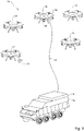
Fig. 1 is a schematic illustration of an active protection system according to the presently disclosed subject matter; and -
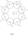
Fig. 2 is a schematic illustration of an example of a configuration of the active protection system illustrated inFig. 1 . - As illustrated in
Fig. 1 , there is provided a system, which is generally indicated at 10. Thesystem 10 is configured to facilitate active protection of a target such as avehicle 12, which may be a tank, a personnel carrier, a marine vehicle, an airborne vehicle, etc., from an incoming threat. The threats are rockets or missiles. - While the
vehicle 12 is not necessarily a component of thesystem 10, references herein to thesystem 10 may, for the sake of clarity, include the vehicle as well, unless otherwise clear from context. References to facilitating protection from a threat (including similar and/or related terms) may comprise some or all activities connected to an operation to neutralize a threat or to otherwise remove a target from being in danger therefrom, including, but not limited to, detecting the threat, destroying it, damaging it, diverting it, prematurely activating it, slowing it, etc. - It will be further appreciated that while the present disclosure and its accompanying drawing are directed toward a system for protecting a land-based vehicle, such a system may be provided for facilitating active protection of other potential targets, including, but not limited to, air vehicles, marine vehicles, buildings, outdoor venues, geographic locations, machinery, etc., without departing from the scope of the presently disclosed subject matter, mutatis mutandis.
- The
system 10 comprises a plurality of unmanned aerial vehicles (UAVs) 14, and at least onecentral platform 16, configured for coordinating operation of the system. According to some examples, theplatform 16 may be configured for installation on thevehicle 12, for example being provided as an independent unit, e.g., configured for mounting on thevehicle 12, or it may be configured for integration with an existing system, e.g., of the vehicle (for example, it may comprise software which is installed on an existing processing unit, e.g., the mission computer, of the vehicle; in such a case, the vehicle itself constitutes the platform of the system). According to other examples, theplatform 16 may be configured for being separate and/or remote from thevehicle 12, for example in a separate vehicle configured to maintain a close proximity to the vehicle, or in a separate location altogether. The platform thus comprises a system controller, which may be a dedicated controller, or part of a controller of an external system, for example one associated with thevehicle 12. - It will be appreciated that while herein the specification and claims, the term controller is used with reference to a single element, it may comprise a combination of elements, which may or may not be in physical proximity to one another, without departing from the scope of the presently disclosed subject matter, mutatis mutandis (i.e., the term controller is used as a logical description, not necessarily as a constructional description of a particular physical computing device). Furthermore, descriptions herein the specification and recitation in the appended claims of multiple controllers includes, and may be embodied in practice by, a single controller. Similarly, such descriptions include providing multiple controllers, with functions described herein as being assigned to a particular controller being carried out in practice by a different one of the controllers, without departing from the scope of the presently disclosed subject matter, mutatis mutandis. In addition, disclosure herein (including recitation in the appended claims) of a controller carrying out, being configured to carry out, or other similar language, implicitly includes other elements of the
system 10 carrying out, being configured to carry out, etc., those functions, without departing from the scope of the presently disclosed subject matter, mutatis mutandis. - While the
platform 16 is described herein with reference to and illustrated in the accompanying drawings as being associated with thevehicle 12, it will be appreciated that it may be associated with a different vehicle, a stationary location, etc., without departing from the scope of the presently disclosed subject matter, mutatis mutandis. It will be further appreciated that theplatform 16 may be provided, mutatis mutandis, such that it is adapted for use with a land vehicle, a marine vehicle, an airborne vehicle such as one of the UAV's 14, etc., without departing from the scope of the presently disclosed subject matter. - The UAV's are configured to operate (i.e., physically fly during operation) in the vicinity of the
vehicle 12, such that it may facilitate in rapidly detecting and/or neutralizing fast-moving threats, such as anti-tank missiles, etc. According to some examples, the vicinity may be considered to be within a distance which does not exceed that distance from which the threat is launched. According to other examples, the vicinity is within about 100 m (about 328 ft.). It will be appreciated that the specific distance may vary, for example exceeding about 100 m (about 328 ft.), but still being less than the distance from which the threat is launched. - Each of the UAV's 14 may be associated with a UAV controller (not illustrated) for directing its operation, in particular the operation of its elements, as will be described below. In addition, the UAV controller is configured to communicate, directly and/or indirectly, with elements of the
UAV 14, for example to receive information and/or data therefrom, and/or to direct operation thereof. It may comprise one or more communications modules to facilitate transmission/receipt of data between elements of theUAV 14, other UAV's, the platform 16 (e.g., the platform controller), and/or external systems, e.g., to be directly controlled thereby. - The UAV controller may be provided as an element of the
UAV 14 or externally thereto, for example on theplatform 16, with elements of the UAV (for example as described below) configured for communicating therewith. - The UAV's 14 may each comprise a location sensor (not illustrated) in order to determine its location. According to some non-limiting examples, the location sensor is configured to determine the absolute location of the
UAV 14, and may thus comprise a global positioning system (GPS) receiver. According to other non-limiting examples, the location sensor is configured to determine the location of theUAV 14 with relation to other elements of thesystem 10, such as other UAV's, theplatform 16, thevehicle 12, and/or with relation to an external system. The location sensor may be further configured to determine the orientation of theUAV 14, absolutely and/or with respect to other elements of thesystem 10 and/or an external system. - According to further examples, the location sensor is configured to facilitate determining the absolute and/or relative location of the
UAV 14, as described above. It may be further configured to utilize data regarding its relative position to other elements, together with GPS data from those elements, in order to refine the calculation of its absolute position, and/or vice versa. - According to some examples, each of the UAV's 14 is configured to move in any direction and/or to hover, i.e., to remain airborne in a single position. Accordingly, it may comprise a plurality of
rotors 18 designed to cooperate to enable movement and/or hovering thereof. According to other examples (not illustrated), each of the UAV's may be a fixed-wing aircraft. According to further examples, thesystem 10 comprises both hovering and fixed-wing UAV's. - The
system 10 is configured to detect an incoming threat. According to some examples, theplatform 16 is configured to perform the detection. Information for facilitating the detection may be collected in any known way, for example using sensors associated with theplatform 16 and/or with thevehicle 12, from an external source (e.g., surveillance vehicles, satellites, etc.), and/or from any other suitable source. - Alternatively or additionally, one or more of the UAV's 14 may comprise
surveillance equipment 20 configured to facilitate detection of an incoming threat. TheUAV 14 may be configured to transmit data gathered by thesurveillance equipment 20 to the platform controller and/or the UAV controller for further processing (i.e., to identify the type of or specific threat, and/or to identify whether the threat's trajectory, and assess the likelihood of it impacting the vehicle and/or where on the vehicle the impact is likely to occur). Thesurveillance equipment 20 may comprise one or more of an optical sensor, infrared sensor, a motion sensor, a thermal sensor, and a pulse-Doppler radar. Thesurveillance equipment 20 may additionally or alternatively comprise any other device which is suitable to facilitate detection of an oncoming threat. - As mentioned, the platform controller may be configured to communicate with the
surveillance equipment 20 and to analyze surveillance data collected thereby in order to determine the presence, identity, trajectory, and/or any other necessary parameter of an incoming threat. According to some examples, the platform controller is configured to utilize surveillance data collected from other sources, e.g., from other UAV's 14 in thesystem 10 and/or from an external system, in making the determination, either in addition to surveillance date received from theUAV 14 or in addition thereto. - It will be appreciated that any surveillance data may also include location data, e.g., associated with the device performing the surveillance.
- According to some examples, multiple UAV's 14 may be configured to independently determine the presence, identity, trajectory, and/or any other necessary parameter of an incoming threat, and verify their determinations with those of the others. They may be configured to selectively perform this verification, e.g., based on the amount of time determined until impact of the threat. Similarly, the platform controller may be configured to make independent assessments of the presence, identity, trajectory, and/or any other necessary parameter of an incoming threat, each based on surveillance data from different subsets of sources (e.g., different UAV's, UAV's and external sources, etc.) and to verify the assessments with one another.
- The
platform 16 and/or one or more of the UAV's 14 may be configured to facilitate neutralizing a detected threat. They may be designed to accomplish this, e.g., by directing deployment of one or more countermeasures, by directly intercepting the threat, or by a combination of both. Theplatform 16/UAV's 14 may be further configured to monitor the threat to determine the success of the neutralization attempt, optionally directing deployment of a second countermeasure in the event of failure. - The countermeasure may be any suitable arrangement for neutralizing the threat before is impacts the
vehicle 12. Typically, the countermeasure is designed to be effective to neutralize a specific type of threat. A threat may be considered to be neutralized if it no longer threatens thevehicle 12, or if its threat to the vehicle is reduced. This may include, inter alia, destruction of the threat, causing it to initiate prematurely and/or improperly, inhibiting its ability to initiate, diverting it, disturbing its stability, implementing countermeasures which interfere with its operation and/or guidance system, etc. A countermeasure may be configured to use one or several methods to neutralize a threat. - Accordingly, the
platform 16 and/or one or more of the UAV's 14 may be configured to direct deployment of the countermeasure most suited against an identified threat, and/or to direct deployment of two or more types of countermeasures against a single threat. - According to some examples, the countermeasure is provided on one of the UAV's 14 itself, or on the
platform 16, for deployment. According to some examples, the countermeasure is an external one, i.e., not deployed by thesystem 10 at all; rather, according to these examples aUAV 14 or other element of the system directs an external apparatus or system to deploy the countermeasure. - The countermeasures may comprise one or more hard-kill countermeasures including, but not limited to, projectiles, pellets, a laser weapon, etc. The countermeasures may comprise one or more soft-kill countermeasures including, but not limited to, chaff, radar jamming, one or more electromagnetic pulses, a laser dazzler, radio frequency decoys, etc.
- According to some non-limiting examples, the
platform 16 and/or one or more of the UAV's 14 carries one or more countermeasures, which may be of the same type or of different types. Accordingly, it may be configured to: - act autonomously to identify and deploy countermeasures to neutralize a threat;
- utilize data from an external source, such as one or more of the other UAV's 14 of the
system 10, to identify a threat which it then deploys countermeasures to neutralize; and/or - be directed to deploy countermeasures to neutralize a threat identified by an external source.
- According to other non-limiting examples, the
platform 16 and/or one or more of the UAV's 14 is configured to direct that one or more external countermeasures be deployed. The external countermeasure may be carried by another of the UAV's 14 or an external system. When directing the deployment of an external countermeasure,platform 16 and/or one or more of the UAV's 14 may further provide data regarding the identity, trajectory, and/or any other relevant parameter of the threat to the apparatus which deploys the countermeasure. The external countermeasure may be part of an active protection system of thevehicle 12. - According to further non-limiting examples, the
system 10 is configured to neutralize the threat by directly intercepting it with one of the UAV's 14. According to some examples, theUAV 14 is be configured to utilize this option as a last resort, for example if time does not permit deployment of a different countermeasure, if no other countermeasures suitable for the threat are available, etc. Direct interception by aUAV 14 may be accomplished in one of several ways: - A
UAV 14 may be configured to direct itself into the path of an incoming threat and/or to attract the threat away from thevehicle 12 and towards it. - Other elements of the system 10 (e.g., other UAV's 14 and/or the platform 16) may be configured to assume control of an intercepting UAV and direct it into the path of an incoming threat.
- According to either of the above, other UAV's 14 and/or elements of the
system 10 may be configured to monitor the threat to determine the success of the neutralization attempt. - According to some examples, some or all of the UAV's 14 may be functionally connected to other elements of the
system 10, for example to receive power therefrom and/or to facilitate communication therebetween. - For example, some or all of the UAV's 14 may be functionally connected to the
vehicle 12 or theplatform 16 by acable 22. In addition or alternatively, some or all of the UAV's 14 may be may be functionally connected thereto wirelessly, as indicated at 24, for example using microwave radiation, or by using multi-coil magnetic beamforming, for example as disclosed in " Magnetic MIMO: How to Charge Your Phone in Your Pocket" by Jouya Jadidian & Dina Katabi, published in "Proceedings of the 20th annual International Conference on Mobile Computing and Networking", by the Association for Computing Machinery, Pages 495-506, the entire contents of which are incorporated herein by reference. It will be appreciated that some methods of wireless power transmissions may be used to facilitate determine the relative location of theUAV 14 with respect to the transmitter, mutatis mutandis. - According to some non-limiting examples, the
UAV 14 is configured to operate directly on power supplied by other elements of the system 10 (e.g., via thecable 22, supplied wirelessly, etc.). - According to other non-limiting examples, the
UAV 14 comprises a battery (not illustrated) for powering its operation, and is configured to utilize electrical power supplied by other elements of thesystem 10 to recharge the battery. According to some modifications, theUAV 14 may be configured to selectively use power directly supplied by other elements of thesystem 10 or from the battery, for example switching from battery power when functionally connected to other elements of the system (e.g., if thecable 22 becomes detached, if the wireless transmission is interrupted, etc.). According to these examples, theUAV 14 may comprise a battery which is smaller than one which would be required if no external source of power were available during flight. In addition, UAV's 14 according to these examples may operate disconnected from thecable 22 for a period of time if necessary (e.g., when directly intercepting an incoming threat). - As mentioned, the functional connection between the
UAV 14 and other elements of thesystem 10 may include communication therebetween. The information may comprise one or more selected from the group including, but not limited to, data gathered thereby, data gathered by other UAVs, instructions by and/or for the UAV for deployment of one or more countermeasures (for example as described above), etc. - According to some non-limiting examples, the UAV controller is configured to perform minimal processing of data gathered thereby, being configured to transmit raw data collected to another element of the
system 10, such as theplatform 14, for processing. This may lower the power required by theUAV 14, and may further enhance the overall processing efficiency of thesystem 10, as data collected by several UAV's 14 may be processed together, thereby eliminating the need to correlate information from eachUAV 14 after initial processing thereby. In addition, there may be fewer constraints associated with providing theplatform 16 with a more powerful processor than with providing theUAV 14 the same processor, as the costs (i.e., weight, power requirements, etc.) associated with processing power, such as power requirements, heat dissipation, weight of the hardware, additional hardware required to protect components in-flight, are typically more easily borne by the platform than by the UAV, or rendered unnecessary by their incorporation therein (for example, the platform may comprise a powerful processor for other functions thereof, which could be used to facilitate processing of data collected by a UAV). - The
system 10 as described above with reference to and as illustrated in the accompanying figures relates to aplatform 16 associated with one or more UAV's 14 to protect avehicle 12. It will be appreciated that several modifications may be provided without departing from the scope of the presently disclosed subject matter, mutatis mutandis. According to some non-limiting examples, thesystem 10 may be configured to provide protection forseveral vehicles 12. In an event, e.g., that more than onevehicle 12 is threatened simultaneously, thesystem 10 may determine which of the vehicles is a higher priority for receiving protection. The determination may be based at least partially on the relative strategic value of the vehicle, the damage it is likely to sustain from the threat, relative to other vehicles, if not protected therefrom, etc. - According to other non-limiting examples, the system may comprise more than one
platform 16. The platforms may be on thesame vehicle 12, for example wherein one or more serves as a redundant platform, on different vehicles, for example wherein thesystem 10 provides protection for more than one vehicle, and/or of different types, for example wherein the system comprises a vehicle-based platform as well as an additional platform. - According to further non-limiting examples, each
system 10 may be configured to operate together with other systems, for example exchanging data therebetween, directing one another to deploy countermeasures, etc. - According to other non-limiting examples, the
system 10 may be configured to adapt to changes in the number of UAV's 14 operating therewith. For example, it may be configured to accommodate a newly addedUAV 14 during operation or to relinquish one of its UAV's 14, e.g., to provide assistance for another system. Accordingly, eachsystem 10 may be configured to communication with other systems, for example to request such assistance, and/or to evaluate its ability to provide it upon receipt of such a request. - According to some examples, the UAV's 14 may be configured to communicate among themselves in order to facilitate identifying and/or neutralizing a threat. For example, the UAV's 14 may operate independently (wholly or partially) of the
platform 16, e.g., by processing surveillance data to identify the threat, and to direct operation of one of the UAV's 14 to act to neutralize it. They may share information, including, but not limited to, raw surveillance data and/or processed information, among themselves to facilitate accomplishing one or more of such tasks, thereby allowing some or all of the UAV's 14 to utilize information gathered by some or all of the other UAV's and/or theplatform 16. Similarly, thesystem 10 may be designed such that theplatform 16 issues instructions to the UAV's 14 to neutralize an identified threat (including information about the threat, e.g., location, trajectory, velocity, threat type, etc.), the UAV's being configured to communicate among themselves in order to determine operational details of the neutralizing, e.g., which UAV should act, etc. - It will be appreciated that the UAV's 14 and/or
platform 16, when carrying out any operation (described herein or otherwise), may be configured to utilize statistical data, based on data gathered from some or all of the other elements of thesystem 10 or of other systems, in order to progressively improve their performance of one or more task. (Such improvements are often referred to as machine learning.) These improvements may relate to identification of threats, neutralizing threats, optimization of one or more of its operations, and/or any other suitable task. - As illustrated schematically in
Fig. 2 , the system is configured to operate such that several UAV's 14 surround thevehicle 12, each being configured to deploy a soft-kill countermeasure which extends a distance r1 therefrom. As the UAV's 14 are spaced far from thevehicle 12, the combined protected area provided by the several UAV's 14 may neutralize a threat at a distance r2 , which is larger than r1 . As the amount of energy required to deploy the soft-kill countermeasure area increases with the distance which it extends from its source, by providing several smaller zones of protection (e.g., each of radius r1 ) to effectively protect a larger zone (e.g., having radius r2 ), the amount of energy required to effect protection to the area defined by the larger radius may be reduced, compared to that required if protection was provided by equipment disposed on thevehicle 12. Accordingly, thesystem 10 may be used to protect against threats which are at a large distance from thevehicle 12, while expending less energy than would be required to protect from such threats using equipment disposed on the vehicle itself. While the above has been described with reference to a soft-kill countermeasure, it will be appreciated that the same applied, mutatis mutandis, to a hard-kill countermeasure. - It will be appreciated that outside of the scope of the claims, e.g., in a situation wherein the direction of the threat is known, the
system 10 may be deployed such that UAV's 14 do not completely surround thevehicle 12, but are disposed, for example, on one side thereof. - It will be appreciated that the
system 10 may be configured to act autonomously, i.e., automatically and/or without user intervention, to detect and neutralize a threat. In addition, as the UAV's 14 may operate at a distance from thevehicle 12, use of thesystem 10 to contribute to protection thereof may result in neutralization of threats at distances which are farther from the vehicle than are typical wherein elements for detection and neutralization are located on the vehicle itself. As neutralization of threats may result in collateral damage to the vehicle 12 (e.g., neutralization of a missile may entail an explosion, which itself may cause damage to the vehicle if it occurs at too small a distance therefrom), increasing the distance at which threats may be neutralized may further protect the vehicle, and, in some cases, decrease the weight of protective armor necessary to shield the vehicle from such collateral damage. - Those skilled in the art to which this invention pertains will readily appreciate that numerous changes, variations, and modifications can be made without departing from the scope of the presently disclosed subject matter, mutatis mutandis.
Claims (15)
- A system (10) for facilitating active protection of a target (12) from a threat, the system comprising:• one or more platforms (16) configured for directing operation of the system;and• a plurality of unmanned aerial vehicles (UAV's; 14) configured to operate in the vicinity of the target, to facilitate detection of said threat and to neutralize said threat,wherein said platform (16) is configured for autonomously detecting said threat and providing instructions to one or more of said UAV's (14) for neutralizing said threat, wherein each of said UAV's (14) is configured for communicating with said platform (16), characterized in that the threat is that of a rocket or missile and in that the system (10) is configured to operate such that several UAV's (14) surround the target (12), each UAV (14) being configured to deploy a soft-kill countermeasure.
- The system (10) according to claim 1, at least some of said UAV's (14) being configured to hover in a fixed location.
- The system (10) according to any one of claims 1 and 2, at least some of said UAV's (14) being fixed-wing aircraft.
- The system (10) according to any one of the preceding claims, wherein at least some of said UAV's (14) are configured to receive power from said platform (16) and/or said target (12).
- The system (10) according to any one of the preceding claims, at least some of said UAV's (14) comprising surveillance equipment (20) configured to facilitate detection of said projectile threat.
- The system (10) according to claim 5, said UAV's (14) being configured for transmitting surveillance data to said platform (16), said platform being configured for processing said surveillance data to detect said projectile threat.
- The system (10) according to any one of the preceding claims, said platform (16) being configured to communicate with an active protection system for directing operation thereof.
- The system (10) according to claim 7, wherein one or more of said UAV's (14) and/or said platform (16) comprises said active protection system.
- The system (10) according to any one of claims 7 and 8, wherein said active protection system comprises one or more hard-kill countermeasures and/or one or more soft-kill countermeasures.
- The system (10) according to any one of the preceding claims, wherein one or more of said UAV's (14) are configured for intercepting said projectile threat to neutralize it.
- The system (10) according to any one of the preceding claims, wherein each of said UAV's (14) comprises a location sensor configured to determine the absolute location thereof.
- The system (10) according to any one of the preceding claims, being configured to determine the relative location of each of the UAV's (14) with respect to the platform (16) and/or other of the UAV's.
- The system (10) according to any one of the preceding claims, wherein said platform (16) is configured for installation on said target (12).
- The system (10) according to any one of the preceding claims, wherein said target (12) is a vehicle.
- The system (10) according to any one of the preceding claims, configured to implement machine learning to improve performance of at least one task.
Applications Claiming Priority (1)
| Application Number | Priority Date | Filing Date | Title |
|---|---|---|---|
| IL252583A IL252583B (en) | 2017-05-29 | 2017-05-29 | Drone-based active protection system |
Publications (2)
| Publication Number | Publication Date |
|---|---|
| EP3410057A1 EP3410057A1 (en) | 2018-12-05 |
| EP3410057B1 true EP3410057B1 (en) | 2022-06-15 |
Family
ID=60942774
Family Applications (1)
| Application Number | Title | Priority Date | Filing Date |
|---|---|---|---|
| EP18174698.3A Active EP3410057B1 (en) | 2017-05-29 | 2018-05-29 | Drone-based active protection system |
Country Status (6)
| Country | Link |
|---|---|
| US (1) | US20180341262A1 (en) |
| EP (1) | EP3410057B1 (en) |
| JP (1) | JP2019023553A (en) |
| KR (1) | KR20180130464A (en) |
| IL (1) | IL252583B (en) |
| SG (1) | SG10201804529PA (en) |
Families Citing this family (12)
| Publication number | Priority date | Publication date | Assignee | Title |
|---|---|---|---|---|
| GB2573827B (en) | 2018-05-18 | 2021-04-14 | Immobileyes Inc | Laser Shield Device |
| US11879705B2 (en) * | 2018-07-05 | 2024-01-23 | Mikael Bror Taveniku | System and method for active shooter defense |
| CN109472520A (en) * | 2018-12-21 | 2019-03-15 | 南京邮电大学 | Multiple no-manned plane method for allocating tasks based on block chain |
| EP3690383A1 (en) * | 2019-02-04 | 2020-08-05 | CMI Defence S.A. | Operational section of armoured vehicles communicating with a flotilla of drones |
| KR102334679B1 (en) * | 2019-02-15 | 2021-12-02 | 최춘화 | Anti-drone system using unmanned aerial vehicle |
| CN109960277A (en) * | 2019-03-08 | 2019-07-02 | 沈阳无距科技有限公司 | Expel unmanned plane and its interference method, device, storage medium and electronic equipment |
| DE102019109360A1 (en) * | 2019-04-09 | 2020-10-15 | Rheinmetall Air Defence Ag | Invention system for defense against RAM targets and / or UAVs as well as methods for defense against RAM targets and / or UAVs |
| JP7413003B2 (en) | 2019-12-20 | 2024-01-15 | 三菱重工業株式会社 | Guidance equipment, air vehicles, air defense systems, and guidance programs |
| JP2023532299A (en) * | 2020-07-01 | 2023-07-27 | アイエムアイ システムズ リミテッド | Incoming threat prevention system and method of use |
| CN112325704B (en) * | 2020-10-20 | 2022-07-29 | 中国人民解放军海军工程大学 | Unmanned aerial vehicle-mounted optical fiber laser false target and use method thereof |
| KR102432021B1 (en) * | 2021-09-07 | 2022-08-16 | 스카이루먼 주식회사 | Method for security communications between relay drone and working drones |
| CN115218723A (en) * | 2022-06-28 | 2022-10-21 | 安徽阿拉丁航空航天有限公司 | High-energy directional beam weapon system with continuous power supply |
Citations (2)
| Publication number | Priority date | Publication date | Assignee | Title |
|---|---|---|---|---|
| US20050051667A1 (en) * | 2001-12-21 | 2005-03-10 | Arlton Paul E. | Micro-rotorcraft surveillance system |
| EP2778598A1 (en) * | 2013-03-14 | 2014-09-17 | BAE Systems PLC | Apparatus for use on unmanned vehicles |
Family Cites Families (6)
| Publication number | Priority date | Publication date | Assignee | Title |
|---|---|---|---|---|
| US9121669B1 (en) * | 1994-09-02 | 2015-09-01 | The Boeing Company | System and method for designating a target for a remote aerial vehicle |
| US9026272B2 (en) * | 2007-12-14 | 2015-05-05 | The Boeing Company | Methods for autonomous tracking and surveillance |
| CA2979232A1 (en) * | 2009-02-02 | 2010-10-28 | Aerovironment | Multimode unmanned aerial vehicle |
| US9841761B2 (en) * | 2012-05-04 | 2017-12-12 | Aeryon Labs Inc. | System and method for controlling unmanned aerial vehicles |
| JP6338911B2 (en) * | 2014-03-28 | 2018-06-06 | 三菱重工業株式会社 | Unmanned aerial vehicle mounting and module armor |
| US20190363821A1 (en) * | 2017-01-10 | 2019-11-28 | AIRSHARE, Inc. | System and method for communicating with a uav |
-
2017
- 2017-05-29 IL IL252583A patent/IL252583B/en unknown
-
2018
- 2018-05-28 SG SG10201804529PA patent/SG10201804529PA/en unknown
- 2018-05-29 EP EP18174698.3A patent/EP3410057B1/en active Active
- 2018-05-29 JP JP2018102124A patent/JP2019023553A/en active Pending
- 2018-05-29 US US15/991,049 patent/US20180341262A1/en not_active Abandoned
- 2018-05-29 KR KR1020180061132A patent/KR20180130464A/en not_active Application Discontinuation
Patent Citations (2)
| Publication number | Priority date | Publication date | Assignee | Title |
|---|---|---|---|---|
| US20050051667A1 (en) * | 2001-12-21 | 2005-03-10 | Arlton Paul E. | Micro-rotorcraft surveillance system |
| EP2778598A1 (en) * | 2013-03-14 | 2014-09-17 | BAE Systems PLC | Apparatus for use on unmanned vehicles |
Also Published As
| Publication number | Publication date |
|---|---|
| JP2019023553A (en) | 2019-02-14 |
| SG10201804529PA (en) | 2018-12-28 |
| KR20180130464A (en) | 2018-12-07 |
| EP3410057A1 (en) | 2018-12-05 |
| US20180341262A1 (en) | 2018-11-29 |
| IL252583A0 (en) | 2017-12-31 |
| IL252583B (en) | 2022-02-01 |
Similar Documents
| Publication | Publication Date | Title |
|---|---|---|
| EP3410057B1 (en) | Drone-based active protection system | |
| US10982935B2 (en) | Methods and apparatuses for active protection from aerial threats | |
| US20220034633A1 (en) | Drone-Based Active Protection System | |
| US20100026554A1 (en) | Active protection method and system | |
| KR102516343B1 (en) | Proximity measures to neutralize target air vehicles | |
| US20220325985A1 (en) | Advanced cooperative defensive military tactics, armor, and systems | |
| EP2979979B1 (en) | Systems and methods for countering an unmanned air vehicle | |
| RU2018126360A (en) | AIR TRANSPORT SYSTEM | |
| US10295312B2 (en) | Methods and apparatuses for active protection from aerial threats | |
| EP2722633A2 (en) | An active protection system | |
| EP3732432A1 (en) | Autonomous weapon system for guidance and combat assessment | |
| US20220097843A1 (en) | Incoming threat protection system and method of using same | |
| EP3320301B1 (en) | Active protection system | |
| Wojtyra et al. | Concept for the construction and application of a counter-UAV defence system | |
| RU2691645C1 (en) | Method of protecting a radar station from unidentifiable small-size unmanned aerial vehicles and a device for realizing said | |
| US11662183B1 (en) | Systems and methods for automomous protection of satellites from hostile orbital attackers | |
| EP4238869A1 (en) | System for collaborative threat evasion tactics coordination | |
| KR20230042693A (en) | Incoming threat protection system and how to use it | |
| Leśnik et al. | Analysis of man-portable systems intercepting miniature unmanned aerial vehicles | |
| US20240085159A1 (en) | Electronic countermeasure cartridge arranged to be loaded into countermeasure dispenser and arranged to irradiate dispensed electromagnetically reflective material |
Legal Events
| Date | Code | Title | Description |
|---|---|---|---|
| PUAI | Public reference made under article 153(3) epc to a published international application that has entered the european phase |
Free format text: ORIGINAL CODE: 0009012 |
|
| STAA | Information on the status of an ep patent application or granted ep patent |
Free format text: STATUS: THE APPLICATION HAS BEEN PUBLISHED |
|
| AK | Designated contracting states |
Kind code of ref document: A1 Designated state(s): AL AT BE BG CH CY CZ DE DK EE ES FI FR GB GR HR HU IE IS IT LI LT LU LV MC MK MT NL NO PL PT RO RS SE SI SK SM TR |
|
| AX | Request for extension of the european patent |
Extension state: BA ME |
|
| STAA | Information on the status of an ep patent application or granted ep patent |
Free format text: STATUS: REQUEST FOR EXAMINATION WAS MADE |
|
| 17P | Request for examination filed |
Effective date: 20190605 |
|
| RBV | Designated contracting states (corrected) |
Designated state(s): AL AT BE BG CH CY CZ DE DK EE ES FI FR GB GR HR HU IE IS IT LI LT LU LV MC MK MT NL NO PL PT RO RS SE SI SK SM TR |
|
| STAA | Information on the status of an ep patent application or granted ep patent |
Free format text: STATUS: EXAMINATION IS IN PROGRESS |
|
| 17Q | First examination report despatched |
Effective date: 20200813 |
|
| STAA | Information on the status of an ep patent application or granted ep patent |
Free format text: STATUS: EXAMINATION IS IN PROGRESS |
|
| STAA | Information on the status of an ep patent application or granted ep patent |
Free format text: STATUS: EXAMINATION IS IN PROGRESS |
|
| GRAP | Despatch of communication of intention to grant a patent |
Free format text: ORIGINAL CODE: EPIDOSNIGR1 |
|
| STAA | Information on the status of an ep patent application or granted ep patent |
Free format text: STATUS: GRANT OF PATENT IS INTENDED |
|
| INTG | Intention to grant announced |
Effective date: 20220112 |
|
| GRAS | Grant fee paid |
Free format text: ORIGINAL CODE: EPIDOSNIGR3 |
|
| GRAA | (expected) grant |
Free format text: ORIGINAL CODE: 0009210 |
|
| STAA | Information on the status of an ep patent application or granted ep patent |
Free format text: STATUS: THE PATENT HAS BEEN GRANTED |
|
| AK | Designated contracting states |
Kind code of ref document: B1 Designated state(s): AL AT BE BG CH CY CZ DE DK EE ES FI FR GB GR HR HU IE IS IT LI LT LU LV MC MK MT NL NO PL PT RO RS SE SI SK SM TR |
|
| REG | Reference to a national code |
Ref country code: CH Ref legal event code: EP Ref country code: GB Ref legal event code: FG4D |
|
| REG | Reference to a national code |
Ref country code: IE Ref legal event code: FG4D |
|
| REG | Reference to a national code |
Ref country code: DE Ref legal event code: R096 Ref document number: 602018036682 Country of ref document: DE |
|
| REG | Reference to a national code |
Ref country code: AT Ref legal event code: REF Ref document number: 1498625 Country of ref document: AT Kind code of ref document: T Effective date: 20220715 |
|
| REG | Reference to a national code |
Ref country code: LT Ref legal event code: MG9D |
|
| REG | Reference to a national code |
Ref country code: NL Ref legal event code: MP Effective date: 20220615 |
|
| PG25 | Lapsed in a contracting state [announced via postgrant information from national office to epo] |
Ref country code: SE Free format text: LAPSE BECAUSE OF FAILURE TO SUBMIT A TRANSLATION OF THE DESCRIPTION OR TO PAY THE FEE WITHIN THE PRESCRIBED TIME-LIMIT Effective date: 20220615 Ref country code: NO Free format text: LAPSE BECAUSE OF FAILURE TO SUBMIT A TRANSLATION OF THE DESCRIPTION OR TO PAY THE FEE WITHIN THE PRESCRIBED TIME-LIMIT Effective date: 20220915 Ref country code: LT Free format text: LAPSE BECAUSE OF FAILURE TO SUBMIT A TRANSLATION OF THE DESCRIPTION OR TO PAY THE FEE WITHIN THE PRESCRIBED TIME-LIMIT Effective date: 20220615 Ref country code: HR Free format text: LAPSE BECAUSE OF FAILURE TO SUBMIT A TRANSLATION OF THE DESCRIPTION OR TO PAY THE FEE WITHIN THE PRESCRIBED TIME-LIMIT Effective date: 20220615 Ref country code: GR Free format text: LAPSE BECAUSE OF FAILURE TO SUBMIT A TRANSLATION OF THE DESCRIPTION OR TO PAY THE FEE WITHIN THE PRESCRIBED TIME-LIMIT Effective date: 20220916 Ref country code: FI Free format text: LAPSE BECAUSE OF FAILURE TO SUBMIT A TRANSLATION OF THE DESCRIPTION OR TO PAY THE FEE WITHIN THE PRESCRIBED TIME-LIMIT Effective date: 20220615 Ref country code: BG Free format text: LAPSE BECAUSE OF FAILURE TO SUBMIT A TRANSLATION OF THE DESCRIPTION OR TO PAY THE FEE WITHIN THE PRESCRIBED TIME-LIMIT Effective date: 20220915 |
|
| REG | Reference to a national code |
Ref country code: AT Ref legal event code: MK05 Ref document number: 1498625 Country of ref document: AT Kind code of ref document: T Effective date: 20220615 |
|
| PG25 | Lapsed in a contracting state [announced via postgrant information from national office to epo] |
Ref country code: RS Free format text: LAPSE BECAUSE OF FAILURE TO SUBMIT A TRANSLATION OF THE DESCRIPTION OR TO PAY THE FEE WITHIN THE PRESCRIBED TIME-LIMIT Effective date: 20220615 Ref country code: LV Free format text: LAPSE BECAUSE OF FAILURE TO SUBMIT A TRANSLATION OF THE DESCRIPTION OR TO PAY THE FEE WITHIN THE PRESCRIBED TIME-LIMIT Effective date: 20220615 |
|
| PG25 | Lapsed in a contracting state [announced via postgrant information from national office to epo] |
Ref country code: NL Free format text: LAPSE BECAUSE OF FAILURE TO SUBMIT A TRANSLATION OF THE DESCRIPTION OR TO PAY THE FEE WITHIN THE PRESCRIBED TIME-LIMIT Effective date: 20220615 |
|
| PG25 | Lapsed in a contracting state [announced via postgrant information from national office to epo] |
Ref country code: SM Free format text: LAPSE BECAUSE OF FAILURE TO SUBMIT A TRANSLATION OF THE DESCRIPTION OR TO PAY THE FEE WITHIN THE PRESCRIBED TIME-LIMIT Effective date: 20220615 Ref country code: SK Free format text: LAPSE BECAUSE OF FAILURE TO SUBMIT A TRANSLATION OF THE DESCRIPTION OR TO PAY THE FEE WITHIN THE PRESCRIBED TIME-LIMIT Effective date: 20220615 Ref country code: RO Free format text: LAPSE BECAUSE OF FAILURE TO SUBMIT A TRANSLATION OF THE DESCRIPTION OR TO PAY THE FEE WITHIN THE PRESCRIBED TIME-LIMIT Effective date: 20220615 Ref country code: PT Free format text: LAPSE BECAUSE OF FAILURE TO SUBMIT A TRANSLATION OF THE DESCRIPTION OR TO PAY THE FEE WITHIN THE PRESCRIBED TIME-LIMIT Effective date: 20221017 Ref country code: ES Free format text: LAPSE BECAUSE OF FAILURE TO SUBMIT A TRANSLATION OF THE DESCRIPTION OR TO PAY THE FEE WITHIN THE PRESCRIBED TIME-LIMIT Effective date: 20220615 Ref country code: EE Free format text: LAPSE BECAUSE OF FAILURE TO SUBMIT A TRANSLATION OF THE DESCRIPTION OR TO PAY THE FEE WITHIN THE PRESCRIBED TIME-LIMIT Effective date: 20220615 Ref country code: CZ Free format text: LAPSE BECAUSE OF FAILURE TO SUBMIT A TRANSLATION OF THE DESCRIPTION OR TO PAY THE FEE WITHIN THE PRESCRIBED TIME-LIMIT Effective date: 20220615 Ref country code: AT Free format text: LAPSE BECAUSE OF FAILURE TO SUBMIT A TRANSLATION OF THE DESCRIPTION OR TO PAY THE FEE WITHIN THE PRESCRIBED TIME-LIMIT Effective date: 20220615 |
|
| PG25 | Lapsed in a contracting state [announced via postgrant information from national office to epo] |
Ref country code: PL Free format text: LAPSE BECAUSE OF FAILURE TO SUBMIT A TRANSLATION OF THE DESCRIPTION OR TO PAY THE FEE WITHIN THE PRESCRIBED TIME-LIMIT Effective date: 20220615 Ref country code: IS Free format text: LAPSE BECAUSE OF FAILURE TO SUBMIT A TRANSLATION OF THE DESCRIPTION OR TO PAY THE FEE WITHIN THE PRESCRIBED TIME-LIMIT Effective date: 20221015 |
|
| REG | Reference to a national code |
Ref country code: DE Ref legal event code: R097 Ref document number: 602018036682 Country of ref document: DE |
|
| PG25 | Lapsed in a contracting state [announced via postgrant information from national office to epo] |
Ref country code: AL Free format text: LAPSE BECAUSE OF FAILURE TO SUBMIT A TRANSLATION OF THE DESCRIPTION OR TO PAY THE FEE WITHIN THE PRESCRIBED TIME-LIMIT Effective date: 20220615 |
|
| PLBE | No opposition filed within time limit |
Free format text: ORIGINAL CODE: 0009261 |
|
| STAA | Information on the status of an ep patent application or granted ep patent |
Free format text: STATUS: NO OPPOSITION FILED WITHIN TIME LIMIT |
|
| PG25 | Lapsed in a contracting state [announced via postgrant information from national office to epo] |
Ref country code: DK Free format text: LAPSE BECAUSE OF FAILURE TO SUBMIT A TRANSLATION OF THE DESCRIPTION OR TO PAY THE FEE WITHIN THE PRESCRIBED TIME-LIMIT Effective date: 20220615 |
|
| 26N | No opposition filed |
Effective date: 20230316 |
|
| PG25 | Lapsed in a contracting state [announced via postgrant information from national office to epo] |
Ref country code: SI Free format text: LAPSE BECAUSE OF FAILURE TO SUBMIT A TRANSLATION OF THE DESCRIPTION OR TO PAY THE FEE WITHIN THE PRESCRIBED TIME-LIMIT Effective date: 20220615 |
|
| REG | Reference to a national code |
Ref country code: DE Ref legal event code: R119 Ref document number: 602018036682 Country of ref document: DE |
|
| REG | Reference to a national code |
Ref country code: CH Ref legal event code: PL |
|
| PG25 | Lapsed in a contracting state [announced via postgrant information from national office to epo] |
Ref country code: MC Free format text: LAPSE BECAUSE OF FAILURE TO SUBMIT A TRANSLATION OF THE DESCRIPTION OR TO PAY THE FEE WITHIN THE PRESCRIBED TIME-LIMIT Effective date: 20220615 |
|
| GBPC | Gb: european patent ceased through non-payment of renewal fee |
Effective date: 20230529 |
|
| REG | Reference to a national code |
Ref country code: BE Ref legal event code: MM Effective date: 20230531 |
|
| PG25 | Lapsed in a contracting state [announced via postgrant information from national office to epo] |
Ref country code: MC Free format text: LAPSE BECAUSE OF FAILURE TO SUBMIT A TRANSLATION OF THE DESCRIPTION OR TO PAY THE FEE WITHIN THE PRESCRIBED TIME-LIMIT Effective date: 20220615 Ref country code: LU Free format text: LAPSE BECAUSE OF NON-PAYMENT OF DUE FEES Effective date: 20230529 Ref country code: LI Free format text: LAPSE BECAUSE OF NON-PAYMENT OF DUE FEES Effective date: 20230531 Ref country code: IT Free format text: LAPSE BECAUSE OF FAILURE TO SUBMIT A TRANSLATION OF THE DESCRIPTION OR TO PAY THE FEE WITHIN THE PRESCRIBED TIME-LIMIT Effective date: 20220615 Ref country code: CH Free format text: LAPSE BECAUSE OF NON-PAYMENT OF DUE FEES Effective date: 20230531 |
|
| REG | Reference to a national code |
Ref country code: IE Ref legal event code: MM4A |
|
| PG25 | Lapsed in a contracting state [announced via postgrant information from national office to epo] |
Ref country code: IE Free format text: LAPSE BECAUSE OF NON-PAYMENT OF DUE FEES Effective date: 20230529 |