EP3409749A1 - Method and apparatus for recovering fibers embedded in a composite material - Google Patents
Method and apparatus for recovering fibers embedded in a composite material Download PDFInfo
- Publication number
- EP3409749A1 EP3409749A1 EP17382330.3A EP17382330A EP3409749A1 EP 3409749 A1 EP3409749 A1 EP 3409749A1 EP 17382330 A EP17382330 A EP 17382330A EP 3409749 A1 EP3409749 A1 EP 3409749A1
- Authority
- EP
- European Patent Office
- Prior art keywords
- furnace chamber
- composite material
- fibers
- thermolysis
- condensable
- Prior art date
- Legal status (The legal status is an assumption and is not a legal conclusion. Google has not performed a legal analysis and makes no representation as to the accuracy of the status listed.)
- Granted
Links
Images


Classifications
-
- C—CHEMISTRY; METALLURGY
- C10—PETROLEUM, GAS OR COKE INDUSTRIES; TECHNICAL GASES CONTAINING CARBON MONOXIDE; FUELS; LUBRICANTS; PEAT
- C10B—DESTRUCTIVE DISTILLATION OF CARBONACEOUS MATERIALS FOR PRODUCTION OF GAS, COKE, TAR, OR SIMILAR MATERIALS
- C10B53/00—Destructive distillation, specially adapted for particular solid raw materials or solid raw materials in special form
- C10B53/07—Destructive distillation, specially adapted for particular solid raw materials or solid raw materials in special form of solid raw materials consisting of synthetic polymeric materials, e.g. tyres
-
- B—PERFORMING OPERATIONS; TRANSPORTING
- B01—PHYSICAL OR CHEMICAL PROCESSES OR APPARATUS IN GENERAL
- B01J—CHEMICAL OR PHYSICAL PROCESSES, e.g. CATALYSIS OR COLLOID CHEMISTRY; THEIR RELEVANT APPARATUS
- B01J19/00—Chemical, physical or physico-chemical processes in general; Their relevant apparatus
- B01J19/24—Stationary reactors without moving elements inside
- B01J19/245—Stationary reactors without moving elements inside placed in series
-
- B—PERFORMING OPERATIONS; TRANSPORTING
- B29—WORKING OF PLASTICS; WORKING OF SUBSTANCES IN A PLASTIC STATE IN GENERAL
- B29B—PREPARATION OR PRETREATMENT OF THE MATERIAL TO BE SHAPED; MAKING GRANULES OR PREFORMS; RECOVERY OF PLASTICS OR OTHER CONSTITUENTS OF WASTE MATERIAL CONTAINING PLASTICS
- B29B17/00—Recovery of plastics or other constituents of waste material containing plastics
- B29B17/04—Disintegrating plastics, e.g. by milling
-
- C—CHEMISTRY; METALLURGY
- C10—PETROLEUM, GAS OR COKE INDUSTRIES; TECHNICAL GASES CONTAINING CARBON MONOXIDE; FUELS; LUBRICANTS; PEAT
- C10B—DESTRUCTIVE DISTILLATION OF CARBONACEOUS MATERIALS FOR PRODUCTION OF GAS, COKE, TAR, OR SIMILAR MATERIALS
- C10B57/00—Other carbonising or coking processes; Features of destructive distillation processes in general
- C10B57/005—After-treatment of coke, e.g. calcination desulfurization
-
- C—CHEMISTRY; METALLURGY
- C10—PETROLEUM, GAS OR COKE INDUSTRIES; TECHNICAL GASES CONTAINING CARBON MONOXIDE; FUELS; LUBRICANTS; PEAT
- C10G—CRACKING HYDROCARBON OILS; PRODUCTION OF LIQUID HYDROCARBON MIXTURES, e.g. BY DESTRUCTIVE HYDROGENATION, OLIGOMERISATION, POLYMERISATION; RECOVERY OF HYDROCARBON OILS FROM OIL-SHALE, OIL-SAND, OR GASES; REFINING MIXTURES MAINLY CONSISTING OF HYDROCARBONS; REFORMING OF NAPHTHA; MINERAL WAXES
- C10G1/00—Production of liquid hydrocarbon mixtures from oil-shale, oil-sand, or non-melting solid carbonaceous or similar materials, e.g. wood, coal
- C10G1/002—Production of liquid hydrocarbon mixtures from oil-shale, oil-sand, or non-melting solid carbonaceous or similar materials, e.g. wood, coal in combination with oil conversion- or refining processes
-
- C—CHEMISTRY; METALLURGY
- C10—PETROLEUM, GAS OR COKE INDUSTRIES; TECHNICAL GASES CONTAINING CARBON MONOXIDE; FUELS; LUBRICANTS; PEAT
- C10G—CRACKING HYDROCARBON OILS; PRODUCTION OF LIQUID HYDROCARBON MIXTURES, e.g. BY DESTRUCTIVE HYDROGENATION, OLIGOMERISATION, POLYMERISATION; RECOVERY OF HYDROCARBON OILS FROM OIL-SHALE, OIL-SAND, OR GASES; REFINING MIXTURES MAINLY CONSISTING OF HYDROCARBONS; REFORMING OF NAPHTHA; MINERAL WAXES
- C10G1/00—Production of liquid hydrocarbon mixtures from oil-shale, oil-sand, or non-melting solid carbonaceous or similar materials, e.g. wood, coal
- C10G1/02—Production of liquid hydrocarbon mixtures from oil-shale, oil-sand, or non-melting solid carbonaceous or similar materials, e.g. wood, coal by distillation
-
- C—CHEMISTRY; METALLURGY
- C10—PETROLEUM, GAS OR COKE INDUSTRIES; TECHNICAL GASES CONTAINING CARBON MONOXIDE; FUELS; LUBRICANTS; PEAT
- C10G—CRACKING HYDROCARBON OILS; PRODUCTION OF LIQUID HYDROCARBON MIXTURES, e.g. BY DESTRUCTIVE HYDROGENATION, OLIGOMERISATION, POLYMERISATION; RECOVERY OF HYDROCARBON OILS FROM OIL-SHALE, OIL-SAND, OR GASES; REFINING MIXTURES MAINLY CONSISTING OF HYDROCARBONS; REFORMING OF NAPHTHA; MINERAL WAXES
- C10G1/00—Production of liquid hydrocarbon mixtures from oil-shale, oil-sand, or non-melting solid carbonaceous or similar materials, e.g. wood, coal
- C10G1/10—Production of liquid hydrocarbon mixtures from oil-shale, oil-sand, or non-melting solid carbonaceous or similar materials, e.g. wood, coal from rubber or rubber waste
-
- C—CHEMISTRY; METALLURGY
- C10—PETROLEUM, GAS OR COKE INDUSTRIES; TECHNICAL GASES CONTAINING CARBON MONOXIDE; FUELS; LUBRICANTS; PEAT
- C10K—PURIFYING OR MODIFYING THE CHEMICAL COMPOSITION OF COMBUSTIBLE GASES CONTAINING CARBON MONOXIDE
- C10K3/00—Modifying the chemical composition of combustible gases containing carbon monoxide to produce an improved fuel, e.g. one of different calorific value, which may be free from carbon monoxide
- C10K3/02—Modifying the chemical composition of combustible gases containing carbon monoxide to produce an improved fuel, e.g. one of different calorific value, which may be free from carbon monoxide by catalytic treatment
-
- B—PERFORMING OPERATIONS; TRANSPORTING
- B01—PHYSICAL OR CHEMICAL PROCESSES OR APPARATUS IN GENERAL
- B01J—CHEMICAL OR PHYSICAL PROCESSES, e.g. CATALYSIS OR COLLOID CHEMISTRY; THEIR RELEVANT APPARATUS
- B01J2219/00—Chemical, physical or physico-chemical processes in general; Their relevant apparatus
- B01J2219/00002—Chemical plants
- B01J2219/00027—Process aspects
- B01J2219/0004—Processes in series
-
- B—PERFORMING OPERATIONS; TRANSPORTING
- B29—WORKING OF PLASTICS; WORKING OF SUBSTANCES IN A PLASTIC STATE IN GENERAL
- B29B—PREPARATION OR PRETREATMENT OF THE MATERIAL TO BE SHAPED; MAKING GRANULES OR PREFORMS; RECOVERY OF PLASTICS OR OTHER CONSTITUENTS OF WASTE MATERIAL CONTAINING PLASTICS
- B29B17/00—Recovery of plastics or other constituents of waste material containing plastics
- B29B17/04—Disintegrating plastics, e.g. by milling
- B29B2017/0424—Specific disintegrating techniques; devices therefor
- B29B2017/0496—Pyrolysing the materials
-
- C—CHEMISTRY; METALLURGY
- C10—PETROLEUM, GAS OR COKE INDUSTRIES; TECHNICAL GASES CONTAINING CARBON MONOXIDE; FUELS; LUBRICANTS; PEAT
- C10G—CRACKING HYDROCARBON OILS; PRODUCTION OF LIQUID HYDROCARBON MIXTURES, e.g. BY DESTRUCTIVE HYDROGENATION, OLIGOMERISATION, POLYMERISATION; RECOVERY OF HYDROCARBON OILS FROM OIL-SHALE, OIL-SAND, OR GASES; REFINING MIXTURES MAINLY CONSISTING OF HYDROCARBONS; REFORMING OF NAPHTHA; MINERAL WAXES
- C10G2300/00—Aspects relating to hydrocarbon processing covered by groups C10G1/00 - C10G99/00
- C10G2300/10—Feedstock materials
- C10G2300/1003—Waste materials
-
- C—CHEMISTRY; METALLURGY
- C10—PETROLEUM, GAS OR COKE INDUSTRIES; TECHNICAL GASES CONTAINING CARBON MONOXIDE; FUELS; LUBRICANTS; PEAT
- C10G—CRACKING HYDROCARBON OILS; PRODUCTION OF LIQUID HYDROCARBON MIXTURES, e.g. BY DESTRUCTIVE HYDROGENATION, OLIGOMERISATION, POLYMERISATION; RECOVERY OF HYDROCARBON OILS FROM OIL-SHALE, OIL-SAND, OR GASES; REFINING MIXTURES MAINLY CONSISTING OF HYDROCARBONS; REFORMING OF NAPHTHA; MINERAL WAXES
- C10G2400/00—Products obtained by processes covered by groups C10G9/00 - C10G69/14
- C10G2400/02—Gasoline
-
- C—CHEMISTRY; METALLURGY
- C10—PETROLEUM, GAS OR COKE INDUSTRIES; TECHNICAL GASES CONTAINING CARBON MONOXIDE; FUELS; LUBRICANTS; PEAT
- C10G—CRACKING HYDROCARBON OILS; PRODUCTION OF LIQUID HYDROCARBON MIXTURES, e.g. BY DESTRUCTIVE HYDROGENATION, OLIGOMERISATION, POLYMERISATION; RECOVERY OF HYDROCARBON OILS FROM OIL-SHALE, OIL-SAND, OR GASES; REFINING MIXTURES MAINLY CONSISTING OF HYDROCARBONS; REFORMING OF NAPHTHA; MINERAL WAXES
- C10G2400/00—Products obtained by processes covered by groups C10G9/00 - C10G69/14
- C10G2400/04—Diesel oil
-
- C—CHEMISTRY; METALLURGY
- C10—PETROLEUM, GAS OR COKE INDUSTRIES; TECHNICAL GASES CONTAINING CARBON MONOXIDE; FUELS; LUBRICANTS; PEAT
- C10G—CRACKING HYDROCARBON OILS; PRODUCTION OF LIQUID HYDROCARBON MIXTURES, e.g. BY DESTRUCTIVE HYDROGENATION, OLIGOMERISATION, POLYMERISATION; RECOVERY OF HYDROCARBON OILS FROM OIL-SHALE, OIL-SAND, OR GASES; REFINING MIXTURES MAINLY CONSISTING OF HYDROCARBONS; REFORMING OF NAPHTHA; MINERAL WAXES
- C10G2400/00—Products obtained by processes covered by groups C10G9/00 - C10G69/14
- C10G2400/06—Gasoil
-
- Y—GENERAL TAGGING OF NEW TECHNOLOGICAL DEVELOPMENTS; GENERAL TAGGING OF CROSS-SECTIONAL TECHNOLOGIES SPANNING OVER SEVERAL SECTIONS OF THE IPC; TECHNICAL SUBJECTS COVERED BY FORMER USPC CROSS-REFERENCE ART COLLECTIONS [XRACs] AND DIGESTS
- Y02—TECHNOLOGIES OR APPLICATIONS FOR MITIGATION OR ADAPTATION AGAINST CLIMATE CHANGE
- Y02P—CLIMATE CHANGE MITIGATION TECHNOLOGIES IN THE PRODUCTION OR PROCESSING OF GOODS
- Y02P20/00—Technologies relating to chemical industry
- Y02P20/141—Feedstock
- Y02P20/143—Feedstock the feedstock being recycled material, e.g. plastics
-
- Y—GENERAL TAGGING OF NEW TECHNOLOGICAL DEVELOPMENTS; GENERAL TAGGING OF CROSS-SECTIONAL TECHNOLOGIES SPANNING OVER SEVERAL SECTIONS OF THE IPC; TECHNICAL SUBJECTS COVERED BY FORMER USPC CROSS-REFERENCE ART COLLECTIONS [XRACs] AND DIGESTS
- Y02—TECHNOLOGIES OR APPLICATIONS FOR MITIGATION OR ADAPTATION AGAINST CLIMATE CHANGE
- Y02W—CLIMATE CHANGE MITIGATION TECHNOLOGIES RELATED TO WASTEWATER TREATMENT OR WASTE MANAGEMENT
- Y02W30/00—Technologies for solid waste management
- Y02W30/50—Reuse, recycling or recovery technologies
- Y02W30/62—Plastics recycling; Rubber recycling
Definitions
- the present disclosure relates to a method and an apparatus for recovering fibers embedded in a composite material, the apparatus comprising a furnace chamber for thermolyzing a volume of the composite material, which is a step of the method.
- a composite material is a material made from two or more components (constituent materials) with different physical or chemical properties that, when combined, produce a material (the composite) with characteristics different from the individual components and superior thereto.
- the individual components enhance each other but remain separate and distinct within the composite.
- the matrix material surrounds and supports the reinforcement materials by maintaining their relative positions, and bestows thermal and environmental resistance upon the composite.
- the reinforcements impart their special mechanical and physical properties to strengthen the matrix, for instance to prevent crack propagation.
- Polymers are typical matrices especially used for fiber-reinforced plastics, wherein the fibers constitute the reinforcement.
- Most common polymer-based composite materials comprise a resin, e.g. epoxy resin.
- resins used for these composites include polyester and epoxy, while glass and carbon fibers are often employed as reinforcement.
- EP2783764 discloses a method consisting in a thermal process in which the composite material is pyrolyzed at a relatively low temperature in a closed furnace chamber with an inactive atmosphere, for example in the form of nitrogen.
- the temperature and combustion conditions are intended for the matrix to be gasified while leaving the fibers more or less intact, thus making recycling possible, at least in principle.
- a method for recovering fibers embedded in a composite material comprises the steps of: loading a furnace chamber (for example, a first furnace chamber, anticipating the possibility of further furnace chambers but without precluding a single furnace chamber) with a volume of the composite material; thermolyzing the composite material in said furnace chamber, resulting in gaseous fraction that is continuously evacuated from the furnace chamber, and a residue of fibers covered with char that is left in the furnace chamber; cracking the gaseous fraction from the thermolysis step, resulting in a mixture of condensable and non-condensable gases; injecting a stream of an oxygen-containing gas into the still hot furnace chamber after the thermolysis is completed therein, in order to burn the char from the fibers in an exothermic combustion.
- a furnace chamber for example, a first furnace chamber, anticipating the possibility of further furnace chambers but without precluding a single furnace chamber
- thermolyzing the composite material in said furnace chamber resulting in gaseous fraction that is continuously evacuated from the furnace chamber, and a
- thermolysis is herein used to encompass the splitting of complex molecules into simpler ones under the influence of heat and catalysts.
- the cracking of the thermolysis gases into condensable and non-condensable gases is an useful way to treat the gaseous residues from the thermolysis because the condensable gases can, for example, be condensed and used as fuel.
- thermolysis may be a pyrolysis, i.e. a thermolysis in the absence of oxygen (or any halogen).
- the thermolysis or the pyrolysis may be performed under vacuum in order to speed it up, for example at 0.1-0.9 bars.
- the oxygen-containing gas may contain O 2 and/or O 3 (ozone).
- O 2 and/or O 3 ozone
- the use of ozone may speed up the exothermic combustion.
- the oxygen-containing gas may be air enriched with 2-20% in volume of oxygen.
- the loading of the furnace chamber may be done by means of a cage that can be filled with the composite material outside the chamber and can be loaded into the chamber very quickly, whereby the aperture time of furnace chamber would be shortened (or even minimized), which would improve the energy efficiency of the process.
- the method further comprises the step of using the non-condensable gases for contributing heat to the furnace chamber in the thermolysis or pyrolysis step, thus improving the energy efficiency of the process.
- the non-condensable gases may be used for cogeneration, which also improves the overall energy efficiency.
- the cracking step may be performed by circulating the gaseous fraction through a reducing agent, particularly through a catalyst, like for example SiC or zeolite.
- two furnace chambers might be used, the above-mentioned first furnace chamber and a second furnace chamber, so that the method would further comprise the steps of:
- thermolysis may be a pyrolysis, and the other variants explained above (in relation to one furnace chamber) may also be applied herein (in relation to two furnace chambers).
- an apparatus for recovering fibers embedded in a composite material comprises a furnace chamber for thermolyzing (or pyrolyzing) a volume of the composite material, which can produce the above-mentioned gaseous fraction, and a reducing agent (e.g. a catalyst) for cracking the gaseous fraction, which can produce the above-mentioned mixture of condensable and non-condensable gases.
- a reducing agent e.g. a catalyst
- the heating of the furnace chamber may be carried out, perhaps partially, by means of a gas burner fueled (at least in part) by the non-condensable gases produced in the cracking step.
- a gas burner fueled (at least in part) by the non-condensable gases produced in the cracking step.
- alternative or complementary means to heat the furnace chamber may also be envisaged, such as radiation means, convection means, induction means, micro-wave means, electric resistances, etc.
- the apparatus of figures 1 and 2 comprises a furnace 1 provided with a furnace chamber 10, a burner 11 for the chamber 10, a first outlet 12 from the chamber 10, an inlet 13 to the chamber 10 and a second outlet 14 therefrom.
- the first outlet 12 leads (through a conduit) to a reducing member 20 comprising a reducing agent 21, for example zeolite or a SiC catalyst.
- a condenser 31 Downstream from the catalyst is a condenser 31, from where non-condensable gases can be brought, through a filter 32, to the burner 11.
- the inlet 13 allows to inject a stream of air (or other oxygen-containing gas) into the furnace chamber 10, and the second outlet 14 is to evacuate combustion gases from the furnace chamber 10 to a separator (e.g. a cyclone) 41 and some further filters 42.
- the apparatus also comprises suitable valves in the conduits.
- the operation with the apparatus is as follows (the goal is to extract clean fibers from a discarded part made of a polymer-based composite material with embedded fibers, e.g. glass or carbon fibers, for example a removed wind turbine blade):
- the reducing agent 21 is thermostated, i.e., its temperature is carefully controlled in order to optimize the cracking reactions.
- the non-condensable gas or gases brought into the burner 11 are burned therein and thus contribute thermal energy to the pyrolysis (at the beginning, when this recycled fuel is not available yet, an external fuel can be used, for example propane), or, alternatively, instead of bringing the non-condensable gas to the burner 11, the non-condensable gas can be used to drive a turbine (not shown) in a cogeneration process.
- the condensed gases can be collected in different containers depending on their condensation temperatures.
- FIG. 3 shows the pyrolysis and cracking processes (steps C, D and E).
- the solid black valves represent open valves and the white valves represent closed valves.
- the straight arrows represent gas flows and the curved arrow at the bottom of the condenser 31 would represent a liquid flow (in case the corresponding bottom valve would be open).
- FIG. 4 shows the exothermic combustion (steps F and G); as before, the solid black valves represent open valves and the white valves represent closed valves, and the straight arrows represent gas flows.
- the multi-pointed arrow in chamber 10 represents the char combustion.
- Step F can be termed 'exothermic sweeping'.
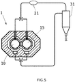
- FIG. 5 shows another example in which the furnace 1 comprises two furnace chambers, a first furnace chamber 10 and a second furnace chamber 15.
- This apparatus can be operated in batch mode as follows:
- the weight-ratio of recycled clean fibers to the fibers initially contained in the composite material was estimated to be of approximately 95%, which shows the effectiveness or the method described above.
- the method further produces energy (from the non-condensable gases) and fuel (the condensable gases).
Landscapes
- Chemical & Material Sciences (AREA)
- Engineering & Computer Science (AREA)
- Oil, Petroleum & Natural Gas (AREA)
- Organic Chemistry (AREA)
- Chemical Kinetics & Catalysis (AREA)
- General Chemical & Material Sciences (AREA)
- Life Sciences & Earth Sciences (AREA)
- Wood Science & Technology (AREA)
- Materials Engineering (AREA)
- Environmental & Geological Engineering (AREA)
- Mechanical Engineering (AREA)
- Combustion & Propulsion (AREA)
- Separation, Recovery Or Treatment Of Waste Materials Containing Plastics (AREA)
- Processing Of Solid Wastes (AREA)
Description
- The present disclosure relates to a method and an apparatus for recovering fibers embedded in a composite material, the apparatus comprising a furnace chamber for thermolyzing a volume of the composite material, which is a step of the method.
- A composite material is a material made from two or more components (constituent materials) with different physical or chemical properties that, when combined, produce a material (the composite) with characteristics different from the individual components and superior thereto. The individual components enhance each other but remain separate and distinct within the composite. There are two main categories of constituent materials: a continuous phase called 'matrix' (or 'binder') and a scattered phase called 'reinforcement'. The matrix material surrounds and supports the reinforcement materials by maintaining their relative positions, and bestows thermal and environmental resistance upon the composite. The reinforcements impart their special mechanical and physical properties to strengthen the matrix, for instance to prevent crack propagation.
- Polymers are typical matrices especially used for fiber-reinforced plastics, wherein the fibers constitute the reinforcement. Most common polymer-based composite materials comprise a resin, e.g. epoxy resin. For example, composite materials are frequently used for the rotor blades of a wind turbine; typical resins used for these composites include polyester and epoxy, while glass and carbon fibers are often employed as reinforcement.
- In view of increasing environmental concerns, an important issue has arisen regarding how to recycle fiber-reinforced plastic members without simply processing such members by mere (and hazardous) combustion or landfilling. In particular, the recycling of wind turbine blades made from composite materials constitutes a problem because of the large dimensions of the blades, and also because of the difficulty of safely pulling the fibers apart from the polymer with the resin, but it is nevertheless advisable to try to recover the fiber content of fiber-reinforced plastics, instead of just disposing of it, in order to reuse the fibers in newly produced fiber-reinforced plastic members, for example new wind turbine blades.
-
EP2783764 discloses a method consisting in a thermal process in which the composite material is pyrolyzed at a relatively low temperature in a closed furnace chamber with an inactive atmosphere, for example in the form of nitrogen. The temperature and combustion conditions are intended for the matrix to be gasified while leaving the fibers more or less intact, thus making recycling possible, at least in principle. - It is an object of the present disclosure to provide a method and an apparatus to efficiently recycle fibers from discarded fiber-reinforced plastic members, thus making it feasible to recover and reuse the fibers.
- In a first aspect, a method for recovering fibers embedded in a composite material is provided. The method comprises the steps of: loading a furnace chamber (for example, a first furnace chamber, anticipating the possibility of further furnace chambers but without precluding a single furnace chamber) with a volume of the composite material; thermolyzing the composite material in said furnace chamber, resulting in gaseous fraction that is continuously evacuated from the furnace chamber, and a residue of fibers covered with char that is left in the furnace chamber; cracking the gaseous fraction from the thermolysis step, resulting in a mixture of condensable and non-condensable gases; injecting a stream of an oxygen-containing gas into the still hot furnace chamber after the thermolysis is completed therein, in order to burn the char from the fibers in an exothermic combustion.
- The term "cracking" is herein used to encompass the splitting of complex molecules into simpler ones under the influence of heat and catalysts. In the present context, the cracking of the thermolysis gases into condensable and non-condensable gases is an useful way to treat the gaseous residues from the thermolysis because the condensable gases can, for example, be condensed and used as fuel.
- The thermolysis (or thermal decomposition) may be a pyrolysis, i.e. a thermolysis in the absence of oxygen (or any halogen). The thermolysis or the pyrolysis may be performed under vacuum in order to speed it up, for example at 0.1-0.9 bars.
- The oxygen-containing gas may contain O2 and/or O3 (ozone). The use of ozone may speed up the exothermic combustion. The oxygen-containing gas may be air enriched with 2-20% in volume of oxygen.
- In an example, the loading of the furnace chamber may be done by means of a cage that can be filled with the composite material outside the chamber and can be loaded into the chamber very quickly, whereby the aperture time of furnace chamber would be shortened (or even minimized), which would improve the energy efficiency of the process.
- In an example, the method further comprises the step of using the non-condensable gases for contributing heat to the furnace chamber in the thermolysis or pyrolysis step, thus improving the energy efficiency of the process. Alternatively or complementarily, the non-condensable gases may be used for cogeneration, which also improves the overall energy efficiency.
- The cracking step may be performed by circulating the gaseous fraction through a reducing agent, particularly through a catalyst, like for example SiC or zeolite.
- In an example, two furnace chambers might be used, the above-mentioned first furnace chamber and a second furnace chamber, so that the method would further comprise the steps of:
- loading the second furnace chamber with a volume of the composite material;
- thermolyzing the composite material in the second furnace chamber, with heat being contributed by the combustion that is taking or has taken place in the first furnace chamber, resulting in a gaseous fraction that is continuously evacuated from the second furnace chamber, and a residue of fibers covered with char that is left in the second furnace chamber;
- cracking the gaseous fraction from the thermolysis step in the second furnace chamber, resulting in a mixture of condensable and non-condensable gases;
- unloading the clean fibers from the first furnace chamber and loading the latter with a volume of the composite material;
- injecting a stream of an oxygen-containing gas into the still hot second furnace chamber after the thermolysis is completed therein, in order to burn the char from the fibers in an exothermic combustion;
- thermolyzing the composite material in the first furnace chamber, with heat being contributed by the combustion that is taking or has taken place in the second furnace chamber, resulting in a gaseous fraction that is continuously evacuated from the first furnace chamber, and a residue of fibers covered with char that is left in the first furnace chamber;
- cracking the gaseous fraction from the thermolysis step in the first furnace chamber, resulting in a mixture of condensable and non-condensable gases;
- unloading the clean fibers from the second furnace chamber and loading the latter with a volume of the composite material;
- injecting a stream of an oxygen-containing gas into the still hot first furnace chamber after the thermolysis is completed therein, in order to burn the char from the fibers in an exothermic combustion.
- In this way, by alternating between the first furnace chamber and the second furnace chamber, the energy efficiency of the process is further improved.
- As before, the thermolysis may be a pyrolysis, and the other variants explained above (in relation to one furnace chamber) may also be applied herein (in relation to two furnace chambers).
- In a second aspect, an apparatus to carry out this two-chamber method is provided.
- In a third aspect, an apparatus for recovering fibers embedded in a composite material is provided. The apparatus comprises a furnace chamber for thermolyzing (or pyrolyzing) a volume of the composite material, which can produce the above-mentioned gaseous fraction, and a reducing agent (e.g. a catalyst) for cracking the gaseous fraction, which can produce the above-mentioned mixture of condensable and non-condensable gases.
- In either apparatus, the heating of the furnace chamber (or chambers) may be carried out, perhaps partially, by means of a gas burner fueled (at least in part) by the non-condensable gases produced in the cracking step. However, alternative or complementary means to heat the furnace chamber may also be envisaged, such as radiation means, convection means, induction means, micro-wave means, electric resistances, etc.
- Further advantages, properties, aspects and features of the present disclosure may be derived from the below-described examples. The above-described features and/or the features disclosed in the claims and/or in the following description of examples can, if required, also be combined with one another even if this is not expressly described in detail.
- Non-limiting examples of the present disclosure will be described in the following, with reference to the appended drawings, in which:
-
figure 1 is a schematic view of an apparatus for recovering fibers embedded in a composite material; -
figure 2 is another schematic view of the apparatus offigure 1 ; -
figure 3 is schematic view that illustrates an use of the apparatus offigure 1 ; -
figure 4 is schematic view that illustrates another use of the apparatus offigure 1 ; and -
figure 5 is a schematic view of two furnace chambers of an apparatus for recovering fibers embedded in a composite material. - The apparatus of
figures 1 and 2 comprises afurnace 1 provided with afurnace chamber 10, aburner 11 for thechamber 10, afirst outlet 12 from thechamber 10, aninlet 13 to thechamber 10 and asecond outlet 14 therefrom. Thefirst outlet 12 leads (through a conduit) to a reducingmember 20 comprising a reducingagent 21, for example zeolite or a SiC catalyst. Downstream from the catalyst is acondenser 31, from where non-condensable gases can be brought, through afilter 32, to theburner 11. - The
inlet 13 allows to inject a stream of air (or other oxygen-containing gas) into thefurnace chamber 10, and thesecond outlet 14 is to evacuate combustion gases from thefurnace chamber 10 to a separator (e.g. a cyclone) 41 and somefurther filters 42. The apparatus also comprises suitable valves in the conduits. - The operation with the apparatus is as follows (the goal is to extract clean fibers from a discarded part made of a polymer-based composite material with embedded fibers, e.g. glass or carbon fibers, for example a removed wind turbine blade):
- A. Cut or pound the composite part into small pieces or fragments.
- B. Introduce a suitable volume of such fragments 18 (
fig. 3 ) into thefurnace chamber 10. - C. Pyrolyze (or, more generally, thermolize) the
composite material 18 present in thefurnace chamber 10 at a temperature of 350-600°C, preferably of about 550°C, until the matrix (for example, resin-made) of the composite material is completely decomposed. - D. Continuously extract the gaseous fraction produced in the pyrolysis through the
first outlet 12, and crack this gaseous fraction by passing it through the reducingagent 21, which is kept at a temperature of 250-400°C, preferably of about 350°C. - E. Bring the gases produced in the cracking process into the
condenser 31, where they are rapidly cooled down (to under 10°C) in order to obtain two different fuels: a condensed gas (i.e. a liquid fuel to be sold or anyhow used) and a non-condensable gas which is separated and brought into theburner 11, after being filtered throughfilter 32. - The reducing
agent 21 is thermostated, i.e., its temperature is carefully controlled in order to optimize the cracking reactions. The non-condensable gas or gases brought into theburner 11 are burned therein and thus contribute thermal energy to the pyrolysis (at the beginning, when this recycled fuel is not available yet, an external fuel can be used, for example propane), or, alternatively, instead of bringing the non-condensable gas to theburner 11, the non-condensable gas can be used to drive a turbine (not shown) in a cogeneration process. The condensed gases can be collected in different containers depending on their condensation temperatures. - Apart from the gaseous fraction, the other result of the pyrolysis is a heap of fibers covered with char 19 (
fig. 4 ), and the operation goes on as follows: - F. Just after the pyrolysis has been completed, inject a stream of an oxygen-containing gas (for example air or oxygen-enriched air, e.g. air enriched with 6%-volume of O2) into the
furnace chamber 10, which is still very hot from the pyrolysis (basically at the same temperature thereof), until the char is burned-out in an exothermic combustion, leaving the fibers clean. - G. Continuously extract the combusted gaseous stream from the
furnace chamber 10 through thesecond outlet 14 and bring said combustion gases into theseparator 41, e.g. a cyclone, where they are suitably treated and filtered (at least a part of the combustion gases are carried through the filters 42). -
Figure 3 shows the pyrolysis and cracking processes (steps C, D and E). The solid black valves represent open valves and the white valves represent closed valves. The straight arrows represent gas flows and the curved arrow at the bottom of thecondenser 31 would represent a liquid flow (in case the corresponding bottom valve would be open). -
Figure 4 shows the exothermic combustion (steps F and G); as before, the solid black valves represent open valves and the white valves represent closed valves, and the straight arrows represent gas flows. The multi-pointed arrow inchamber 10 represents the char combustion. Step F can be termed 'exothermic sweeping'. -
Figure 5 shows another example in which thefurnace 1 comprises two furnace chambers, afirst furnace chamber 10 and asecond furnace chamber 15. This apparatus can be operated in batch mode as follows: - I.
Load furnace chambers - II. Pyrolyze the composite material present in
first furnace chamber 10. - III. Exothermically sweep the char-covered fibers in
first furnace chamber 10. - IV. Pyrolyze the composite material present in
second furnace chamber 15 using heat from step III; this pyrolysis and the exothermic sweeping of step III can start simultaneously. - V. Unload the clean fibers from
first furnace chamber 10 and load a volume of composite material therein. - VI. Exothermically sweep the char-covered fibers in
second furnace chamber 15. - VII. Pyrolyze the composite material present in
first furnace chamber 10 using heat from step VI; this pyrolysis and the exothermic sweeping of step VI can start simultaneously. - VIII. Unload the clean fibers from
second furnace chamber 15 and, unless the current batch operation is finished, load a volume of composite material therein. - IX. Continue from step III.
- In experimental examples, the weight-ratio of recycled clean fibers to the fibers initially contained in the composite material was estimated to be of approximately 95%, which shows the effectiveness or the method described above. Besides, the method further produces energy (from the non-condensable gases) and fuel (the condensable gases).
- Although only a number of examples have been disclosed herein, other alternatives, modifications, uses and/or equivalents thereof are possible. Furthermore, all possible combinations of the described examples are also covered. Thus, the scope of the present disclosure should not be limited by particular examples, but should be determined only by a fair reading of the claims that follow. If reference signs related to drawings are placed in parentheses in a claim, they are solely for attempting to increase the intelligibility of the claim, and shall not be construed as limiting the scope of the claim.
Claims (15)
- A method for recovering fibers embedded in a composite material, comprising the steps of:- loading a first furnace chamber (10) with a volume of the composite material (18);- thermolyzing the composite material in said furnace chamber, resulting in a gaseous fraction that is continuously evacuated from the furnace chamber, and a residue of fibers covered with char (19) that is left in the furnace chamber;- cracking the gaseous fraction from the thermolysis step, resulting in a mixture of condensable and non-condensable gases;- injecting a stream of an oxygen-containing gas into the still hot furnace chamber after the thermolysis is completed therein, in order to burn the char from the fibers in an exothermic combustion.
- The method of claim 1, wherein the thermolysis is a pyrolysis.
- The method of claim 1 or 2, wherein the cracking step is performed by circulating the gaseous fraction through a reducing agent (21).
- The method according to any of the preceding claims, comprising the step of using the non-condensable gas or gases for contributing heat to the furnace chamber (10) in the thermolysis step.
- The method according to any of the preceding claims, wherein the thermolysis is performed under vacuum.
- The method according to any of claims 2 to 5, wherein at least one pyrolysis step is performed with the furnace chamber (10) at a temperature of 350-600°C.
- The method according to any of the preceding claims, wherein the oxygen-containing gas used in at least one combustion step is air enriched with 2-20% in volume of oxygen.
- The method according to any of claims 3 to 7, wherein the reducing agent (21) is kept at a temperature of 250-400°C.
- The method according to any of the preceding claims, wherein at least one thermolysis step lasts between 1 and 4 hours.
- The method according to any of the preceding claims, wherein at least one combustion step lasts between 1 and 4 hours.
- The method according to any of the preceding claims, characterized by using a second furnace chamber (15) and by further comprising the steps of:- loading the second furnace chamber (15) with a volume of the composite material;- thermolyzing the composite material in the second furnace chamber, with heat being contributed by the combustion that is taking or has taken place in the first furnace chamber (10), resulting in a gaseous fraction that is continuously evacuated from the second furnace chamber, and a residue of fibers covered with char that is left in the second furnace chamber;- cracking the gaseous fraction from the thermolysis step in the second furnace chamber, resulting in a mixture of condensable and non-condensable gases;- unloading the clean fibers from the first furnace chamber and loading the latter with a volume of the composite material;- injecting a stream of an oxygen-containing gas into the still hot second furnace chamber after the thermolysis is completed therein, in order to burn the char from the fibers in an exothermic combustion;- thermolyzing the composite material in the first furnace chamber, with heat being contributed by the combustion that is taking or has taken place in the second furnace chamber, resulting in a gaseous fraction that is continuously evacuated from the first furnace chamber, and a residue of fibers covered with char that is left in the first furnace chamber;- cracking the gaseous fraction from the thermolysis step in the first furnace chamber, resulting in a mixture of condensable and non-condensable gases;- unloading the clean fibers from the second furnace chamber and loading the latter with a volume of the composite material;- injecting a stream of an oxygen-containing gas into the still hot first furnace chamber after the thermolysis is completed therein, in order to burn the char from the fibers in an exothermic combustion.
- The method of claim 11, wherein the thermolysis is a pyrolysis.
- An apparatus for recovering fibers embedded in a composite material, comprising a furnace chamber (10; 15) for thermolyzing a volume of the composite material, which can produce a gaseous fraction, characterized by also comprising a reducing agent (21) for cracking the gaseous fraction, which can produce a mixture of condensable and non-condensable gases.
- The apparatus of claim 13, comprising a condenser (31) for condensing the condensable gas.
- An apparatus to carry out the method of claim 11.
Priority Applications (5)
| Application Number | Priority Date | Filing Date | Title |
|---|---|---|---|
| ES17382330T ES2867390T3 (en) | 2017-06-02 | 2017-06-02 | Procedure and apparatus for recovering fibers incorporated in a composite material |
| EP17382330.3A EP3409749B1 (en) | 2017-06-02 | 2017-06-02 | Method and apparatus for recovering fibers embedded in a composite material |
| PCT/EP2018/064539 WO2018220217A1 (en) | 2017-06-02 | 2018-06-01 | Method and apparatus for recovering fibers embedded in a composite material |
| CN201880034940.9A CN110945107A (en) | 2017-06-02 | 2018-06-01 | Method and apparatus for recovering fibers embedded in composite materials |
| US16/618,743 US11168261B2 (en) | 2017-06-02 | 2018-06-01 | Method and apparatus for recovering fibers embedded in a composite material |
Applications Claiming Priority (1)
| Application Number | Priority Date | Filing Date | Title |
|---|---|---|---|
| EP17382330.3A EP3409749B1 (en) | 2017-06-02 | 2017-06-02 | Method and apparatus for recovering fibers embedded in a composite material |
Publications (2)
| Publication Number | Publication Date |
|---|---|
| EP3409749A1 true EP3409749A1 (en) | 2018-12-05 |
| EP3409749B1 EP3409749B1 (en) | 2021-02-24 |
Family
ID=59152804
Family Applications (1)
| Application Number | Title | Priority Date | Filing Date |
|---|---|---|---|
| EP17382330.3A Active EP3409749B1 (en) | 2017-06-02 | 2017-06-02 | Method and apparatus for recovering fibers embedded in a composite material |
Country Status (5)
| Country | Link |
|---|---|
| US (1) | US11168261B2 (en) |
| EP (1) | EP3409749B1 (en) |
| CN (1) | CN110945107A (en) |
| ES (1) | ES2867390T3 (en) |
| WO (1) | WO2018220217A1 (en) |
Cited By (5)
| Publication number | Priority date | Publication date | Assignee | Title |
|---|---|---|---|---|
| US11168261B2 (en) | 2017-06-02 | 2021-11-09 | Bcircular Composites, Sociedad Limitada | Method and apparatus for recovering fibers embedded in a composite material |
| GB2606215A (en) * | 2021-04-29 | 2022-11-02 | Greenology Teesside Ltd | Blade recycling system and method |
| CN115532212A (en) * | 2022-07-19 | 2022-12-30 | 上海治实合金科技有限公司 | Conveyer belt type carbon removing furnace |
| CN116515509A (en) * | 2023-04-17 | 2023-08-01 | 东南大学 | Device and method for recycling waste fan blade glass fibers through thermal conversion |
| WO2024161062A1 (en) * | 2023-02-02 | 2024-08-08 | Efesto Green Reactors, S.L. | Pyrolytic device for the recycling of composite materials |
Families Citing this family (2)
| Publication number | Priority date | Publication date | Assignee | Title |
|---|---|---|---|---|
| US12053908B2 (en) | 2021-02-01 | 2024-08-06 | Regen Fiber, Llc | Method and system for recycling wind turbine blades |
| CN119610477B (en) * | 2025-01-14 | 2025-12-16 | 华中科技大学 | A molten salt pyrolysis recovery system and method for discarded hydrogen storage cylinders |
Citations (6)
| Publication number | Priority date | Publication date | Assignee | Title |
|---|---|---|---|---|
| US20040173239A1 (en) * | 2001-04-30 | 2004-09-09 | Erik Grove-Nielsen | Method for recycling composite materials |
| EP1577366A2 (en) * | 2004-03-14 | 2005-09-21 | Ozmotech Pty. Ltd. | Process for conversion of waste material to liquid fuel |
| US20070179326A1 (en) * | 2004-03-14 | 2007-08-02 | Garry Baker | Process and plant for conversion of waste material to liquid fuel |
| JP2008285601A (en) * | 2007-05-18 | 2008-11-27 | Hideto Itatsu | Method for regenerative treatment of carbon fiber |
| EP2783764A1 (en) | 2013-03-28 | 2014-10-01 | ELG Carbon Fibre International GmbH | Pyrolysis assembly and method for the recovery of carbon fibres from plastics containing carbon fibre |
| EP3023478A2 (en) * | 2014-11-19 | 2016-05-25 | Embraer , S.A. | A process for recycling composite materials and a system for treating waste gases |
Family Cites Families (5)
| Publication number | Priority date | Publication date | Assignee | Title |
|---|---|---|---|---|
| US6758150B2 (en) * | 2001-07-16 | 2004-07-06 | Energy Associates International, Llc | System and method for thermally reducing solid and liquid waste and for recovering waste heat |
| CA2536344C (en) * | 2003-08-21 | 2009-04-07 | International Environmental Solutions Corporation | Chamber support for pyrolytic waste treatment system |
| EP2679659B1 (en) * | 2012-06-29 | 2016-08-24 | Global Gateways Lux HoldCo S.A. | Method and plant for production of a fuel gas from waste |
| MY181058A (en) * | 2015-02-17 | 2020-12-16 | Qt Hydraulic Sdn Bhd | An apparatus and method for pyrolysis |
| EP3409749B1 (en) | 2017-06-02 | 2021-02-24 | Bcircular Composites, Sociedad Limitada | Method and apparatus for recovering fibers embedded in a composite material |
-
2017
- 2017-06-02 EP EP17382330.3A patent/EP3409749B1/en active Active
- 2017-06-02 ES ES17382330T patent/ES2867390T3/en active Active
-
2018
- 2018-06-01 US US16/618,743 patent/US11168261B2/en active Active
- 2018-06-01 WO PCT/EP2018/064539 patent/WO2018220217A1/en not_active Ceased
- 2018-06-01 CN CN201880034940.9A patent/CN110945107A/en active Pending
Patent Citations (6)
| Publication number | Priority date | Publication date | Assignee | Title |
|---|---|---|---|---|
| US20040173239A1 (en) * | 2001-04-30 | 2004-09-09 | Erik Grove-Nielsen | Method for recycling composite materials |
| EP1577366A2 (en) * | 2004-03-14 | 2005-09-21 | Ozmotech Pty. Ltd. | Process for conversion of waste material to liquid fuel |
| US20070179326A1 (en) * | 2004-03-14 | 2007-08-02 | Garry Baker | Process and plant for conversion of waste material to liquid fuel |
| JP2008285601A (en) * | 2007-05-18 | 2008-11-27 | Hideto Itatsu | Method for regenerative treatment of carbon fiber |
| EP2783764A1 (en) | 2013-03-28 | 2014-10-01 | ELG Carbon Fibre International GmbH | Pyrolysis assembly and method for the recovery of carbon fibres from plastics containing carbon fibre |
| EP3023478A2 (en) * | 2014-11-19 | 2016-05-25 | Embraer , S.A. | A process for recycling composite materials and a system for treating waste gases |
Cited By (5)
| Publication number | Priority date | Publication date | Assignee | Title |
|---|---|---|---|---|
| US11168261B2 (en) | 2017-06-02 | 2021-11-09 | Bcircular Composites, Sociedad Limitada | Method and apparatus for recovering fibers embedded in a composite material |
| GB2606215A (en) * | 2021-04-29 | 2022-11-02 | Greenology Teesside Ltd | Blade recycling system and method |
| CN115532212A (en) * | 2022-07-19 | 2022-12-30 | 上海治实合金科技有限公司 | Conveyer belt type carbon removing furnace |
| WO2024161062A1 (en) * | 2023-02-02 | 2024-08-08 | Efesto Green Reactors, S.L. | Pyrolytic device for the recycling of composite materials |
| CN116515509A (en) * | 2023-04-17 | 2023-08-01 | 东南大学 | Device and method for recycling waste fan blade glass fibers through thermal conversion |
Also Published As
| Publication number | Publication date |
|---|---|
| US11168261B2 (en) | 2021-11-09 |
| CN110945107A (en) | 2020-03-31 |
| WO2018220217A1 (en) | 2018-12-06 |
| ES2867390T3 (en) | 2021-10-20 |
| EP3409749B1 (en) | 2021-02-24 |
| US20200165525A1 (en) | 2020-05-28 |
Similar Documents
| Publication | Publication Date | Title |
|---|---|---|
| US11168261B2 (en) | Method and apparatus for recovering fibers embedded in a composite material | |
| DK3114192T3 (en) | THERMOCHEMICAL PROCEDURE FOR RECOVERING GLASS FIBER Reinforced Plastic Waste Material | |
| KR101558432B1 (en) | Device for manufacturing recycled carbon fibers, and method for manufacturing recycled carbon fibers | |
| JP5947828B2 (en) | Fiber-containing resin processing apparatus and processing method | |
| JP5891082B2 (en) | Collection method of carbon fiber | |
| EP1526956A1 (en) | Method and apparatus for recovering carbon and/or glass fibers from a composite material | |
| WO2013089587A1 (en) | Method for producing carbon black from scrap rubber | |
| EP3023478B1 (en) | A process for recycling composite materials | |
| DK1850977T3 (en) | Microwave gasification, pyrolysis and recycling of waste and other organic materials | |
| KR102258647B1 (en) | Device for recycling composite material comprising carbon fiber and/or glass fiber reinforcement and recycling method using the device | |
| CN108826326A (en) | High molecular material continous way processing method and equipment | |
| CN107099883A (en) | A kind of carbon fibre reinforced composite regeneration treating method and device | |
| CN107345000A (en) | The recovery method of fibre reinforced composites | |
| CN113355116B (en) | System for processing recycled composite material | |
| KR101352017B1 (en) | Apparatus for separating copper from ground waste electric wire and method thereof | |
| JP2024149385A (en) | Apparatus and method for recovering carbon and glass fibers from composite materials | |
| CN114990733A (en) | Apparatus for producing regenerated carbon fiber and method for producing regenerated carbon fiber | |
| CN101270289A (en) | A kind of wood tar production process | |
| Grau García et al. | Method and apparatus for recovering fibers embedded in a composite material | |
| JP2014156544A (en) | Manufacturing apparatus and manufacturing method of carbonized material | |
| RU2291168C1 (en) | Method of the rubber-containing wastes reprocessing and the installation for the method realization (versions) | |
| EP4450178A1 (en) | Method for valorization of waste material | |
| CN110181714A (en) | A kind of recycling and reusing method of polymer matrix composite waste | |
| KR20040110292A (en) | The equipment that extract fuel oil in lungs tire | |
| CN1373085A (en) | Method for making activated carbon from carbon powder regenerated by pyrolysis of waste tires |
Legal Events
| Date | Code | Title | Description |
|---|---|---|---|
| PUAI | Public reference made under article 153(3) epc to a published international application that has entered the european phase |
Free format text: ORIGINAL CODE: 0009012 |
|
| STAA | Information on the status of an ep patent application or granted ep patent |
Free format text: STATUS: THE APPLICATION HAS BEEN PUBLISHED |
|
| AK | Designated contracting states |
Kind code of ref document: A1 Designated state(s): AL AT BE BG CH CY CZ DE DK EE ES FI FR GB GR HR HU IE IS IT LI LT LU LV MC MK MT NL NO PL PT RO RS SE SI SK SM TR |
|
| AX | Request for extension of the european patent |
Extension state: BA ME |
|
| STAA | Information on the status of an ep patent application or granted ep patent |
Free format text: STATUS: REQUEST FOR EXAMINATION WAS MADE |
|
| 17P | Request for examination filed |
Effective date: 20190605 |
|
| RBV | Designated contracting states (corrected) |
Designated state(s): AL AT BE BG CH CY CZ DE DK EE ES FI FR GB GR HR HU IE IS IT LI LT LU LV MC MK MT NL NO PL PT RO RS SE SI SK SM TR |
|
| STAA | Information on the status of an ep patent application or granted ep patent |
Free format text: STATUS: EXAMINATION IS IN PROGRESS |
|
| 17Q | First examination report despatched |
Effective date: 20191118 |
|
| RAP1 | Party data changed (applicant data changed or rights of an application transferred) |
Owner name: CONSEJO SUPERIOR DE INVESTIGACIONES CIENTIFICAS (C Owner name: THERMAL RECYCLING OF COMPOSITES, S.L. |
|
| RAP1 | Party data changed (applicant data changed or rights of an application transferred) |
Owner name: BCIRCULAR COMPOSITES, SOCIEDAD LIMITADA Owner name: CONSEJO SUPERIOR DE INVESTIGACIONES CIENTIFICAS (CSIC) |
|
| GRAP | Despatch of communication of intention to grant a patent |
Free format text: ORIGINAL CODE: EPIDOSNIGR1 |
|
| STAA | Information on the status of an ep patent application or granted ep patent |
Free format text: STATUS: GRANT OF PATENT IS INTENDED |
|
| INTG | Intention to grant announced |
Effective date: 20200916 |
|
| RAP1 | Party data changed (applicant data changed or rights of an application transferred) |
Owner name: CONSEJO SUPERIOR DE INVESTIGACIONES CIENTIFICAS (CSIC) Owner name: BCIRCULAR COMPOSITES, SOCIEDAD LIMITADA |
|
| GRAS | Grant fee paid |
Free format text: ORIGINAL CODE: EPIDOSNIGR3 |
|
| GRAA | (expected) grant |
Free format text: ORIGINAL CODE: 0009210 |
|
| STAA | Information on the status of an ep patent application or granted ep patent |
Free format text: STATUS: THE PATENT HAS BEEN GRANTED |
|
| AK | Designated contracting states |
Kind code of ref document: B1 Designated state(s): AL AT BE BG CH CY CZ DE DK EE ES FI FR GB GR HR HU IE IS IT LI LT LU LV MC MK MT NL NO PL PT RO RS SE SI SK SM TR |
|
| REG | Reference to a national code |
Ref country code: CH Ref legal event code: EP |
|
| REG | Reference to a national code |
Ref country code: AT Ref legal event code: REF Ref document number: 1364441 Country of ref document: AT Kind code of ref document: T Effective date: 20210315 |
|
| REG | Reference to a national code |
Ref country code: IE Ref legal event code: FG4D |
|
| REG | Reference to a national code |
Ref country code: DE Ref legal event code: R096 Ref document number: 602017033170 Country of ref document: DE |
|
| REG | Reference to a national code |
Ref country code: LT Ref legal event code: MG9D |
|
| REG | Reference to a national code |
Ref country code: NL Ref legal event code: MP Effective date: 20210224 |
|
| PG25 | Lapsed in a contracting state [announced via postgrant information from national office to epo] |
Ref country code: LT Free format text: LAPSE BECAUSE OF FAILURE TO SUBMIT A TRANSLATION OF THE DESCRIPTION OR TO PAY THE FEE WITHIN THE PRESCRIBED TIME-LIMIT Effective date: 20210224 Ref country code: BG Free format text: LAPSE BECAUSE OF FAILURE TO SUBMIT A TRANSLATION OF THE DESCRIPTION OR TO PAY THE FEE WITHIN THE PRESCRIBED TIME-LIMIT Effective date: 20210524 Ref country code: HR Free format text: LAPSE BECAUSE OF FAILURE TO SUBMIT A TRANSLATION OF THE DESCRIPTION OR TO PAY THE FEE WITHIN THE PRESCRIBED TIME-LIMIT Effective date: 20210224 Ref country code: GR Free format text: LAPSE BECAUSE OF FAILURE TO SUBMIT A TRANSLATION OF THE DESCRIPTION OR TO PAY THE FEE WITHIN THE PRESCRIBED TIME-LIMIT Effective date: 20210525 Ref country code: FI Free format text: LAPSE BECAUSE OF FAILURE TO SUBMIT A TRANSLATION OF THE DESCRIPTION OR TO PAY THE FEE WITHIN THE PRESCRIBED TIME-LIMIT Effective date: 20210224 Ref country code: NO Free format text: LAPSE BECAUSE OF FAILURE TO SUBMIT A TRANSLATION OF THE DESCRIPTION OR TO PAY THE FEE WITHIN THE PRESCRIBED TIME-LIMIT Effective date: 20210524 Ref country code: PT Free format text: LAPSE BECAUSE OF FAILURE TO SUBMIT A TRANSLATION OF THE DESCRIPTION OR TO PAY THE FEE WITHIN THE PRESCRIBED TIME-LIMIT Effective date: 20210624 |
|
| REG | Reference to a national code |
Ref country code: AT Ref legal event code: MK05 Ref document number: 1364441 Country of ref document: AT Kind code of ref document: T Effective date: 20210224 |
|
| PG25 | Lapsed in a contracting state [announced via postgrant information from national office to epo] |
Ref country code: SE Free format text: LAPSE BECAUSE OF FAILURE TO SUBMIT A TRANSLATION OF THE DESCRIPTION OR TO PAY THE FEE WITHIN THE PRESCRIBED TIME-LIMIT Effective date: 20210224 Ref country code: NL Free format text: LAPSE BECAUSE OF FAILURE TO SUBMIT A TRANSLATION OF THE DESCRIPTION OR TO PAY THE FEE WITHIN THE PRESCRIBED TIME-LIMIT Effective date: 20210224 Ref country code: RS Free format text: LAPSE BECAUSE OF FAILURE TO SUBMIT A TRANSLATION OF THE DESCRIPTION OR TO PAY THE FEE WITHIN THE PRESCRIBED TIME-LIMIT Effective date: 20210224 Ref country code: PL Free format text: LAPSE BECAUSE OF FAILURE TO SUBMIT A TRANSLATION OF THE DESCRIPTION OR TO PAY THE FEE WITHIN THE PRESCRIBED TIME-LIMIT Effective date: 20210224 Ref country code: LV Free format text: LAPSE BECAUSE OF FAILURE TO SUBMIT A TRANSLATION OF THE DESCRIPTION OR TO PAY THE FEE WITHIN THE PRESCRIBED TIME-LIMIT Effective date: 20210224 |
|
| PG25 | Lapsed in a contracting state [announced via postgrant information from national office to epo] |
Ref country code: IS Free format text: LAPSE BECAUSE OF FAILURE TO SUBMIT A TRANSLATION OF THE DESCRIPTION OR TO PAY THE FEE WITHIN THE PRESCRIBED TIME-LIMIT Effective date: 20210624 |
|
| REG | Reference to a national code |
Ref country code: ES Ref legal event code: FG2A Ref document number: 2867390 Country of ref document: ES Kind code of ref document: T3 Effective date: 20211020 |
|
| PG25 | Lapsed in a contracting state [announced via postgrant information from national office to epo] |
Ref country code: EE Free format text: LAPSE BECAUSE OF FAILURE TO SUBMIT A TRANSLATION OF THE DESCRIPTION OR TO PAY THE FEE WITHIN THE PRESCRIBED TIME-LIMIT Effective date: 20210224 Ref country code: CZ Free format text: LAPSE BECAUSE OF FAILURE TO SUBMIT A TRANSLATION OF THE DESCRIPTION OR TO PAY THE FEE WITHIN THE PRESCRIBED TIME-LIMIT Effective date: 20210224 Ref country code: AT Free format text: LAPSE BECAUSE OF FAILURE TO SUBMIT A TRANSLATION OF THE DESCRIPTION OR TO PAY THE FEE WITHIN THE PRESCRIBED TIME-LIMIT Effective date: 20210224 Ref country code: SM Free format text: LAPSE BECAUSE OF FAILURE TO SUBMIT A TRANSLATION OF THE DESCRIPTION OR TO PAY THE FEE WITHIN THE PRESCRIBED TIME-LIMIT Effective date: 20210224 |
|
| REG | Reference to a national code |
Ref country code: DE Ref legal event code: R097 Ref document number: 602017033170 Country of ref document: DE |
|
| PG25 | Lapsed in a contracting state [announced via postgrant information from national office to epo] |
Ref country code: SK Free format text: LAPSE BECAUSE OF FAILURE TO SUBMIT A TRANSLATION OF THE DESCRIPTION OR TO PAY THE FEE WITHIN THE PRESCRIBED TIME-LIMIT Effective date: 20210224 Ref country code: RO Free format text: LAPSE BECAUSE OF FAILURE TO SUBMIT A TRANSLATION OF THE DESCRIPTION OR TO PAY THE FEE WITHIN THE PRESCRIBED TIME-LIMIT Effective date: 20210224 Ref country code: DK Free format text: LAPSE BECAUSE OF FAILURE TO SUBMIT A TRANSLATION OF THE DESCRIPTION OR TO PAY THE FEE WITHIN THE PRESCRIBED TIME-LIMIT Effective date: 20210224 |
|
| PLBE | No opposition filed within time limit |
Free format text: ORIGINAL CODE: 0009261 |
|
| STAA | Information on the status of an ep patent application or granted ep patent |
Free format text: STATUS: NO OPPOSITION FILED WITHIN TIME LIMIT |
|
| PG25 | Lapsed in a contracting state [announced via postgrant information from national office to epo] |
Ref country code: MC Free format text: LAPSE BECAUSE OF FAILURE TO SUBMIT A TRANSLATION OF THE DESCRIPTION OR TO PAY THE FEE WITHIN THE PRESCRIBED TIME-LIMIT Effective date: 20210224 Ref country code: AL Free format text: LAPSE BECAUSE OF FAILURE TO SUBMIT A TRANSLATION OF THE DESCRIPTION OR TO PAY THE FEE WITHIN THE PRESCRIBED TIME-LIMIT Effective date: 20210224 |
|
| REG | Reference to a national code |
Ref country code: CH Ref legal event code: PL |
|
| 26N | No opposition filed |
Effective date: 20211125 |
|
| PG25 | Lapsed in a contracting state [announced via postgrant information from national office to epo] |
Ref country code: SI Free format text: LAPSE BECAUSE OF FAILURE TO SUBMIT A TRANSLATION OF THE DESCRIPTION OR TO PAY THE FEE WITHIN THE PRESCRIBED TIME-LIMIT Effective date: 20210224 |
|
| REG | Reference to a national code |
Ref country code: BE Ref legal event code: MM Effective date: 20210630 |
|
| PG25 | Lapsed in a contracting state [announced via postgrant information from national office to epo] |
Ref country code: LU Free format text: LAPSE BECAUSE OF NON-PAYMENT OF DUE FEES Effective date: 20210602 |
|
| PG25 | Lapsed in a contracting state [announced via postgrant information from national office to epo] |
Ref country code: LI Free format text: LAPSE BECAUSE OF NON-PAYMENT OF DUE FEES Effective date: 20210630 Ref country code: IE Free format text: LAPSE BECAUSE OF NON-PAYMENT OF DUE FEES Effective date: 20210602 Ref country code: CH Free format text: LAPSE BECAUSE OF NON-PAYMENT OF DUE FEES Effective date: 20210630 |
|
| PG25 | Lapsed in a contracting state [announced via postgrant information from national office to epo] |
Ref country code: IS Free format text: LAPSE BECAUSE OF FAILURE TO SUBMIT A TRANSLATION OF THE DESCRIPTION OR TO PAY THE FEE WITHIN THE PRESCRIBED TIME-LIMIT Effective date: 20210624 |
|
| PG25 | Lapsed in a contracting state [announced via postgrant information from national office to epo] |
Ref country code: BE Free format text: LAPSE BECAUSE OF NON-PAYMENT OF DUE FEES Effective date: 20210630 |
|
| PG25 | Lapsed in a contracting state [announced via postgrant information from national office to epo] |
Ref country code: CY Free format text: LAPSE BECAUSE OF FAILURE TO SUBMIT A TRANSLATION OF THE DESCRIPTION OR TO PAY THE FEE WITHIN THE PRESCRIBED TIME-LIMIT Effective date: 20210224 |
|
| PG25 | Lapsed in a contracting state [announced via postgrant information from national office to epo] |
Ref country code: HU Free format text: LAPSE BECAUSE OF FAILURE TO SUBMIT A TRANSLATION OF THE DESCRIPTION OR TO PAY THE FEE WITHIN THE PRESCRIBED TIME-LIMIT; INVALID AB INITIO Effective date: 20170602 |
|
| PG25 | Lapsed in a contracting state [announced via postgrant information from national office to epo] |
Ref country code: MK Free format text: LAPSE BECAUSE OF FAILURE TO SUBMIT A TRANSLATION OF THE DESCRIPTION OR TO PAY THE FEE WITHIN THE PRESCRIBED TIME-LIMIT Effective date: 20210224 |
|
| PG25 | Lapsed in a contracting state [announced via postgrant information from national office to epo] |
Ref country code: TR Free format text: LAPSE BECAUSE OF FAILURE TO SUBMIT A TRANSLATION OF THE DESCRIPTION OR TO PAY THE FEE WITHIN THE PRESCRIBED TIME-LIMIT Effective date: 20210224 |
|
| PG25 | Lapsed in a contracting state [announced via postgrant information from national office to epo] |
Ref country code: MT Free format text: LAPSE BECAUSE OF FAILURE TO SUBMIT A TRANSLATION OF THE DESCRIPTION OR TO PAY THE FEE WITHIN THE PRESCRIBED TIME-LIMIT Effective date: 20210224 |
|
| PGFP | Annual fee paid to national office [announced via postgrant information from national office to epo] |
Ref country code: DE Payment date: 20250627 Year of fee payment: 9 |
|
| PGFP | Annual fee paid to national office [announced via postgrant information from national office to epo] |
Ref country code: GB Payment date: 20250627 Year of fee payment: 9 |
|
| PGFP | Annual fee paid to national office [announced via postgrant information from national office to epo] |
Ref country code: FR Payment date: 20250625 Year of fee payment: 9 |
|
| PGFP | Annual fee paid to national office [announced via postgrant information from national office to epo] |
Ref country code: ES Payment date: 20250701 Year of fee payment: 9 |
|
| PGFP | Annual fee paid to national office [announced via postgrant information from national office to epo] |
Ref country code: IT Payment date: 20250619 Year of fee payment: 9 |