EP3409537A1 - Kopfabschnitt für eine rückblickvorrichtung - Google Patents
Kopfabschnitt für eine rückblickvorrichtung Download PDFInfo
- Publication number
- EP3409537A1 EP3409537A1 EP18175142.1A EP18175142A EP3409537A1 EP 3409537 A1 EP3409537 A1 EP 3409537A1 EP 18175142 A EP18175142 A EP 18175142A EP 3409537 A1 EP3409537 A1 EP 3409537A1
- Authority
- EP
- European Patent Office
- Prior art keywords
- rear view
- section
- view means
- mirror
- head
- Prior art date
- Legal status (The legal status is an assumption and is not a legal conclusion. Google has not performed a legal analysis and makes no representation as to the accuracy of the status listed.)
- Granted
Links
Images


Classifications
-
- B—PERFORMING OPERATIONS; TRANSPORTING
- B60—VEHICLES IN GENERAL
- B60R—VEHICLES, VEHICLE FITTINGS, OR VEHICLE PARTS, NOT OTHERWISE PROVIDED FOR
- B60R1/00—Optical viewing arrangements; Real-time viewing arrangements for drivers or passengers using optical image capturing systems, e.g. cameras or video systems specially adapted for use in or on vehicles
- B60R1/02—Rear-view mirror arrangements
- B60R1/08—Rear-view mirror arrangements involving special optical features, e.g. avoiding blind spots, e.g. convex mirrors; Side-by-side associations of rear-view and other mirrors
- B60R1/081—Rear-view mirror arrangements involving special optical features, e.g. avoiding blind spots, e.g. convex mirrors; Side-by-side associations of rear-view and other mirrors avoiding blind spots, e.g. by using a side-by-side association of mirrors
Definitions
- the invention relates to a head section for a rear view device for a motor vehicle in line with the pre-amble of claim 1.
- the head section has casing means comprising at least one housing section and a lid section arranged on a side of the housing section which faces away from a driving direction of the motor vehicle, at least one electronic unit arranged in a hollow area formed between the housing section and the lid section, a first rear view means for displaying a first side or rear area of the motor vehicle in relation to the driving direction, and a second rear view means for displaying a second side or rear area of the motor vehicle in relation to the driving direction.
- Mirrors or rear view means such as those including a camera pod, are typically exposed to the outside environment when used as a side view mirror secured to the outside of a vehicle and when used inside a vehicle as an internal rear view mirror.
- Rear view means are typically made up of many components which require a number of different assembly parts and are complicated and expensive to manufacture.
- rear view means when exposed to the outside environment, rear view means are subject to dirt or debris entering within the assembly.
- a rear view means may include improved protection from the outside environment such rear view means fail to provide a full and expansive field of view including a wide angle view as may be desired by a driver for viewing the driver's blind spot.
- a compact and easy to manufacture head section for a rear view device is provided.
- the second rear view means is arranged on the lid section, with the lid section and the second rear view means including a combined, single-piece component, and the lid section includes a polymeric substrate, which is coated with a chromium-based reflective coating in the region of the combined, single-piece component for providing the second rear view means in form of a reflective element.
- a head section for a rear view device for a motor vehicle includes a casing means including at least one housing section and a lid section arranged on a side of the housing section which faces away from a driving direction of the motor vehicle, at least one electronic unit arranged in a hollow area formed between the housing section and the lid section, a first rear view means for displaying a first side or rear area of the motor vehicle in relation to the driving direction, and a second rear view means for displaying a second side or rear area of the motor vehicle in relation to the driving direction, where the second rear view means is arranged on the lid section, with the lid section and the second rear view means forming a combined, single-piece component, and where the lid section includes a polymeric substrate, which is coated with a chromium-based reflective coating in the region of the combined, single-piece component for providing the second rear view means where the second rear view means is a reflective element.
- the lid section may include a bezel section in addition to the coated, combined, single-piece component providing a second rear view means section.
- the polymeric substrate may also be coated in the bezel section.
- the coating in the bezel section may include a chromium-based reflective coating.
- the coating in the bezel section may differ from the coating in the second rear view means section with respect to at least one of color and reflectivity.
- the housing section and the lid section may seal the hollow area of the head section from an outside environment over an entire circumference of the hollow area, or the housing section, the lid section and the first rear view means may seal the hollow area of the head section from an outside environment over an entire circumference of the hollow area.
- the lid section may further include a first groove between the bezel section and at least one of the first rear view means section and the second rear view means section.
- the multi-function backing plate may include a shoulder being provided between the first and the second rear view means section.
- the alloy may be a binary alloy of chromium and the dopant material.
- the electronic unit may include a setting facility for the rear view device. This makes it possible to set the rear view device in a simple manner.
- the setting facility can be arranged on the upper surface of the flat portion of the lid section which faces towards the hollow area.
- the setting facility comprises a setting unit with at least one lighting means which can be locked or is locked relative to a rear view means, and by means of which a directable or directed light beam can be emitted, which is at least almost solely perceivable in a specified operating position by a driver of a motor vehicle and/or a control unit.
- the rear view means is easy to adjust in a position which conforms to the regulations.
- the housing section and/or the lid section in particular the edge portion, includes a transparent and/or translucent area through which the light beam emitted by the lighting means can penetrate outwards at least almost unimpeded.
- the transparent and/or translucent area can in general be designed in any manner required. It is advantageous when the transparent and/or translucent area comprises a recess, in particular throughout, and/or a translucent and/or transparent material such as glass, in particular smoked glass, or plastic.
- the light beam emitted from the lighting means is sufficiently bundled in order to be perceivable almost solely in the specified operating position by the driver of a motor vehicle and/or the control unit.
- the setting unit comprises at least one optical element which can be functionally assigned or is assigned to the lighting means, with which the light beam emitted by the lighting means can at least be bundled.
- the lid section and the housing section surround a hollow area in an almost entirely sealing manner, electronic devices can be provided in the hollow area which require no housing. As a result, the head section and the rear view device can be compact in design.
- driver and “driver of the vehicle” relates here to the person controlling the main parameters of the vehicle, such as for example direction, speed and/or altitude, e.g. normally the person located in the location specified for the controlling person, for example a seat, but can also relate to any other person or entity within or outside of the vehicle.
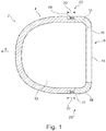
- FIG. 1 shows the lid section 6 comprising a flat portion 16 and two edge portions 18 which extend diagonally to the flat portion 16.
- the lid section 6 comprises a multiple-part component which is designed as a dual-part injection molded element.
- the flat portion 16 is formed from a first lid part and the two edge portions 18 are formed from a second lid part.
- the two edge portions 18 grip the housing section 4 from outside, wherein they overlap the housing section 4 in a coupling portion 20.
- the edge portions 18 includes a lid part which acts as a sealing means 22.
- the sealing means 22 additionally includes a sealing element which is designed as an O-ring 24. It should be appreciated that the sealing means 22 and sealing element or O-ring 24 that is positioned between the lid section 6 and the housing section 4 may also be used in the embodiments of FIGs. 2 to 7
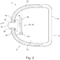
- FIG. 2 shows the head section 2 with an electronic unit 10 being arranged in the hollow area 12.
- the electronic unit 10 comprises a printed circuit board 26 and a lamp 28.
- a retaining device 28 is provided, which also rests on the housing section 4.
- the housing section is formed from a first housing part 30 which is opaque and non-translucent.
- the first housing part 30 of the housing section 4 comprises an opening 32.
- the opening 32 is part of a light window 34 which enables an outward penetration of light from the electronic unit 10 which comprises the printed circuit board 26 and the lamp 28 and is designed as a lighting unit 36.
- an optical element 38 is provided which is arranged at the opening 32.
- the optical element 38 can comprise a light fiber and/or a light disc.
- a housing seal 40 is arranged between the optical element 38 and the first housing part 30 of the housing section 4.
- FIG. 3 shows the head section 2 in which the housing section 4 includes a second housing part 42, which is arranged on an outer side which faces away from the hollow area 12 of the first housing part 41.
- the second housing part 42 includes a transparent and/or translucent area, at least in the area of the light window 34.
- FIG. 4 which shows a lid section 100 of the invention that includes a bezel section 120 and a rim section 180 extending between a first rear view means 300 and a second rear view means 400 arranged on the lid section 100.
- the second rear view means 400 is a so called spotter having a wider field of view than the first rear view means 300.
- the first rear view means 300 can include a reflective element in the form of a mirror glass coated with a chrome or silver layer.
- any other known rear view means can be used instead, such as a display.
- the second rear view means 400 may be provided by a coating on chromium base applied directly on the lid section 100.
- the lid section 100 can be formed out of a polymeric substrate with the bezel section 120 and a combined, single-piece component onto which the chromium-based reflective coating is applied to provide the second rear view means. Further details on the coating is described in US Patent Publication No. US 2017/0158138 A1 , which is herein incorporated by a reference in its entirety for all purposes.
- the rim 180 can be provided with a transparent surface to which a blind spot indicator is fixed as described in US Patent No. 8,779,911 B2 , which is herein incorporated by reference in its entirety for all purposes.
- the bezel section 120', 120" can be provided with an undercut 130', 130" for locking the lid section 100', 100" to the respective, not shown housing section such that the inside of the head section is sealed to the outside in line with the teaching of US Patent Publication No. US 2016/0129841 A1 .
- the lid section includes, in addition to the bezel section, the combined, single-piece component which is to be coated with a chromium-based reflective coating to form the second rear view means 400.
- the combined, single-piece component is referred to as second rear view means section 160', 160".
- the respective section 160', 160" can be flat or curved.
- the second rear view means section 160', 160" is flat and inclined. Between the second rear view means section 160', 160" and the respective bezel section 120', 120", a first groove 200', 200" can be provided.
- the lid section can also be provided with a first rear view means section 140', 140", thus forming a multi-function backing plate.
- the first rear view means is moveable together with the second rear view means as both rear view means are moveable together with a complete head section due to the fact that the lid section 100 is locked to the housing section. That is, the entire mirror assembly including the housing, the lid, and the one or more rear view means may be adjustable inwardly, outwardly, upwardly, and/or downwardly.
- the housing section can comprise two parts to facilitate the assembly of the head section.
- the housing section can have one or more light windows as described in US Patent Publication No. US 2016/0129841 A1 .
- step 210' being provided between the two rear view means sections 140', 160' such that a reflective element providing the first rear view means 300' can be attached below the second rear view means surface 140', for example via an adhesive.
- first rear view means 300 be provided with a recess 320 into which the second rear view means 400 extends, as shown in FIG. 4 .
- the second rear view means 400 may be provided by the chromium-based reflective coating. It is also possible to coat the lid section 100 not only in its second rear view means section 160', but also in its bezel section and/or its first rear view means section. The coatings might be different. In particular, a different color could be chosen for the coating in the bezel section compared to the coating in the first rear view means section and/or the second rear view means section.
- the rim 180, the groove 200', the groove 220" and/or the groove 230" may or may not be coated. If there is a coating, it might be different from the one in the bezel section and/or in the rear view means sections.
- the lid section includes a polymeric substrate, which is preferably injection molded into the required form.
- the lid section may not be formed with a first rear view means section, or may be formed with a first rear view means section which does not extend to the complete area of the first rear view means, as for example illustrated in FIG. 7 .
- the lid section 100'" may include a first rear view means section 140" which has an extension providing a second rear view means section 160", with the respective extension being sufficient for an attachment of the reflective element of the first rear view means 300'" for example via an adhesive layer 310'".
- the first rear view means does not have to be fixedly secured to the lid section at all in order to be moveable with respect to the head section of the rear view device.
- the simple lid section 100, 100', 100" or 100'" of the invention it is possible to reduce the number of parts and thus the time needed for assembling the head section of a rear view device.
- the head section becomes more compact. It is also advantageous to provide a sealed head section in order to reduce the parts needed in connection with any electronic unit provided within the head section, in particular by omitting a housing of the electronic unit.
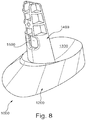
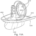
- head sections may be used with a movable head assembly of an external rear view device having a base assembly 10, a frame means 20, an articulation assembly 30 and a casing 40. These parts will be described in the following description with reference to FIGS. 8-12B .
- a moveable head assembly of an external rear view device is for example described in European Patent Application No. 16198759.9 , which is hereby incorporated by reference in its entirety for all purposes.
- This application describes that a head section belonging to a head assembly of an external rear view device, in particular in the form of a mirror head of an external rear view mirror, can be articulated inboard/outboard and up/down using an articulation means, in particular a glass actuator, around a spherical joint, with spherical seats being provided between parts moving relative to each other such that they can rotate around two articulation axes perpendicular to each other having a common joint point.
- This ensures the maintenance of current end user functionality while offering significant smaller mirror size, with a reduction of size up to 30%.
- the unique layout of the internal mechanism with its spherical seats enhances packaging and performances.
- the articulation assembly is also supported and protected for impact using the spherical seats, in particular due to the arrangement of frame means between the articulation assembly and a casing of the head assembly.
- the casing being assembled from several casing elements, one of which is secured to the moveable part of the articulation assembly, improves the weight distribution and reduces total housing frontal area on the vehicle which in turn improves aero performance and, thus, provides a higher fuel efficiency.
- the pivot system used for the rear view device with the single pivot point for two articulation axes permits a mirror adjustment movement while providing dynamic mirror performance and mirror impact support.
- the base assembly 1000 may include a foot 1200 provided with a spherical seat 1300 from which a shaft type carrier part 1400 extends, with the carrier part 1400 being provided with a cable exit 1500.
- the foot 1200 can be closed at its end opposite the spherical seat 1300 by an attachment part 1100 discussed with respect to FIGS. 12a and 12b below.
- the base assembly 1000 is fixedly secured to a motor vehicle (not shown) via the attachment part 1100 when in use.
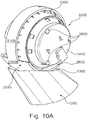
- FIGS. 9A and 9B depict the frame means 2000 fixedly secured to the base assembly 1000.
- the frame means 2000 is provided by a support part 2100 more or less with a ring shape, two spherical seats 2200 and 2500 provided by extensions 2200a, 2200b and 2500a and a fixation part 2300 into which the carrier part 1400 of the base assembly 1000 is inserted such that the lower spherical seat 2200 in FIGS. 9A and 9B is facing the spherical seat 13 of the foot 12.
- the extensions 2200a, 2200b and 2500a extend from opposite sides of the fixation part 2300, with two lower extensions 2200a, 2200b providing a lower spherical seat 2200 and the upper spherical seat 2500 being provided by an upper extension 2500a.
- the fixation part 2300 is provided with a cable exit 2400 in alignment with the cable exit 1500 of the carrier part 1400.
- a screw (not shown) can be entered into a screw hole 2700 provided by the fixation part 2300 and the carrier part 1400.
- the lower casing element 4200 is provided with a base part 4600 arranged between the foot 1200 and the frame means 2000, in particular the lower extension of the frame means.
- the base part 4600 is provided with a lower spherical seat 4700 cooperating with the spherical seat 1300 of the foot 1200 and an upper spherical seat 4800 cooperating with the lowest spherical seat 2200 of the frame means 2000.
- the overall structure is that of three parts spheres with the inner part sphere provided by the frame means 2000 and the outer part sphere provided by the foot 1200 of the base assembly 1000 being fixed, whereas the part sphere provided by the lower casing element 4200, and being arranged in the middle can be moved around two articulation axes in order to provide an inbound/outboard and up/down movement.
- Attached to the attachment part 4400 is a not shown mirror glass which can thus be moved via the articulation assembly 3000 to fulfil the legal field of view requirements of the rear view mirror.
- FIG. 11B shows the subassembly of FIG. 11A together with the fixed part 3200 and movable part 3400 attached between the carrier part 1400 of the base assembly 1000 and the attachment part 4400 of the lower casing 4200.
- the articulation assembly 3000 also includes not shown drive means, in particular including two motors for the movement of the moveable part 3400 around the two articulation axes, and a control system 3600, for the drive means which is partly shown in FIGS. 12A and 12B .
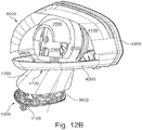
- FIG. 12A shows the subassembly provided by the base assembly 1000, the articulation assembly 3000 and the lower casing element 4200, but also an upper casing element 4100 of the casing 4000 and a camera 5000 both being attached to the lower casing element 4200.
- FIG. 12B shows the subassembly of FIG. 12A from an opposite side, still without the casing 4000 closed via a non-shown additional casing element to complete a head assembly 6000.
- FIG. 12B shows in addition to the upper casing element 4100 and the lower casing element 4200 a bezel 4900 attached to the upper and lower casing elements 4100, 4200.
- the bezel 4900 surrounds the not shown mirror glass of the completely assembled external rear view mirror.
- the head assembly 6000 or rather the mirror head as a whole can be articulated using the articulation assembly 3000 in particular via the movable part 3400.
- the movable part 3400 is connected to the drive system which can be a part of the control system 3600.
- the control system 3600 can also comprise memory means for memorizing a position of the movable 3400 and, thus, the mirror glass attached thereto via the attachment part 4400.
- the support part 2100 is provided in form of an actuator ring which is clipped onto the fixed part 3200 to provide improved support in an impact situation. Due to its upper spherical seat 2500, the frame assembly 2000 is ensuring a smooth movement of the upper casing element 4100 which is also provided with an internal spherical seat, not shown.
- the arrangement of the support part 2100 with its extensions 2200a, 2200b, and 2500a providing the spherical seats 2200, 2500 relative to the movable upper and lower casing elements 4100, 4200 provide a support and stiffness in all three directions during dynamic and impact situations.
- the result is a smaller mirror system offering the customer a unique external rear view mirror weight as well as aero and vehicle fuel efficiency benefit.
- FIG. 2 492 145 Another moveable head assembly of an external rear view device is for example described in European Patent No. 2 492 145 , which is hereby incorporated by reference in its entirety for all purposes.
- This patent refers to an external rear view mirror with a mirror head and a mirror base.
- the external rear view mirror with a mirror head and a mirror base is covered with at least one body element in the form of a body frame, a body cap and a mirror base cover, and a mirror glass that is installed rigidly relative to the mirror head.
- the mirror head rests on the mirror base, and the body cover of the mirror head is composed of multiple pieces of the body frame and the body cap.
- the mirror base is equipped with a mirror base cover where the body cap has an opening designed for the passage of the mirror base and the mirror base cover.
- the mirror base is rigidly connected to a mirror carrier that carries an electrical glass adjustment drive where the glass adjustment drive is connected to at least one body element.
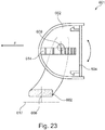
- FIG. 13 shows a sectional view through the x-z plane in vehicle coordinates, where x represents the longitudinal axis of the vehicle.
- the head section or rear view means 501 includes a base 502, which is rotatably connected to a support 503.
- the head 510 is thereby pivotable about the axis 508, so that the head can be hinged in a parking position in the direction of the vehicle.
- an electrical drive for the tilting movement is provided.
- the base 502 as well as the support 503 are clad with plastic covers.
- a mirror foot cover 505 conceals the technical design; the mirror support 503 is concealed by a housing cap 506 and a housing frame 507.
- the mechanical connection to the outer contour 504 of the vehicle is not described in detail. Since the longitudinal section of FIG. 13 extends through the axis of the mirror foot, the glass adjustment drive is not visible.
- FIG. 14 shows the mirror head from FIG. 13 in a section along the y-axis.
- the axis of rotation 508 can be seen around which the mirror head 510 rotates.
- the mirror support 503 is rigidly connected to the housing frame 507 and the housing cap 506 and, during its movement against the mirror base, carries with its mirror foot cover these housing elements.
- a commercial glass adjustment drive 515 is mounted on the mirror support.
- This drive is, for example, a drive as known from EP 2017127 , have a half-shell-shaped housing and a turntable 512 which can be displaced therewith, which generally has a planar contact surface for connecting the mirror glass 511.
- the mirror glass 511 is held in a glass support plate 516, as illustrated in FIG.
- the glass 16 or is installed on the glass adjustment drive in such a way that it can be pivoted into the desired position by means of two adjusting elements of the glass adjustment drive via the rotary table 512.
- the installation of the glass on the glass support plate 516 is provided for reasons of fragmentation protection.
- FIGS. 15A-15C show views of an aspect of the inventive solution.
- the mirror glass 511 is no gap between the glass and the housing is installed directly in the mirror head.
- the mirror glass 511 is not pivoted to the housing elements.
- the mirror glass 511 need not be enclosed or covered by a mirror glass support in this embodiment.
- the splinter protection can be guaranteed also heads by simply applying an adhesive film.
- the mirror head 510 is seated on a mirror 502.
- the case covers the mirror head are either multipart constructed with rack 507 and housing cap 506 or consist of a single component.
- the mirror 502 is provided with a mirror base. 505.
- the mirror base 505 a recess 513 into which the lens of a lighting as a perimeter light, a position light, a warning or an indicator can be integrated.
- the opening 514 must be larger than the diameter of the mirror foot cover 505.
- the mirror head 510 moves against the mirror base so that the opening 514 must be adapted depending on the displacement movements of the mirror head. Since splashing water could penetrate into the mirror head through the opening 514, in another embodiment. it is provided to close the opening around the mirror foot cover with a flexible membrane.
- FIGS. 16 and 17 show the mirror housing construction without housing covers.
- the mirror base 502 is integrally connected to the mirror support 503'.
- the glass adjustment drive 515 is firmly installed on the mirror support 503'.
- the glass adjustment drive 515 is also a commercial drive with a hemispherical housing and a flat turntable 512. This rotary table 512 is rotated by the drive against the hemispherical housing.
- a mirror glass carrier 516, which carries the mirror glass 511, is mounted on the rotary table 512.
- the mirror glass carrier 516 is not only a flat plate, but is designed as a plate with a mount 518 connected thereto. The support 518 overcomes the distance between the turntable 512 of the glass adjustment drive and the mirror glass plane with the mirror glass 511.
- FIG. 18 shows that the mount 518 does not have a parallel construction between the turntable 512 of the glass adjustment drive and the mirror glass 511.
- the turntable 512 is inclined by an acute angle ⁇ against the mirror surface.
- the holder is designed as a hollow cylinder whose end faces are cut at different angles.
- the mirror glass carrier 516 has clips 517 along the outer edge of the mirror glass. These clips 517 are received by counterparts in the housing cover 506 and serve for connection to the housing cover elements of the mirror head, such as the housing cap 506 and/or the housing frame 507. It does not matter here whether the housing cover is designed in one or more parts.
- the housing cover is rigidly connected to the mirror glass carrier 516 and the turntable 512 of the glass adjustment drive with the clips.
- the turntable 512 of the glass adjustment drive 515 rotates against its hemispherical housing and the mirror support 503'.
- the entire structure, consisting of the mirror glass support 516, the mirror glass 511 and the housing cover 506, rotates against the mirror support 503' and thus against the mirror base 502.
- FIGS. 19 and 20 show the mirror foot 502 with mirror support 503' as a one-piece component.
- the mirror foot 502 is formed integrally with the mirror support 503' made of metal casting.
- the mirror support and the mirror foot can also be produced in several pieces and then rigidly connected to one another.
- the fastening element 502' serves for mechanical connection to the vehicle, but is rigidly connected to the mirror foot 502 in the case of use. It is only important that no movement is possible between mirror base 502 and mirror support 503'.
- the mirror base 502 is designed as a hollow cylinder in order to allow the electrical connection to be carried out.
- the mirror foot can be configured in one or more parts.
- the mirror foot 502 is constructed in several parts and has an unlocking line 532 which connects the hollow cylinder 502 with the fastening element 502' fastened to the vehicle.
- the disengagement line 532 is provided for the emergency and allows the mirror to break off at this point in the event of an impact. It will be appreciated that the mirror foot assembly is considered to be rigid in use, and the disengagement line is not seen as a possibility of movement for use.
- the mirror foot 502 opens into the mirror carrier 503', which has been designed as a triangular plate 530, for example.
- the carrier plate 530 has webs 531, which are provided as screw domes for fastening the glass adjustment drive.
- the carrier plate 530 has a central recess 533.
- the semi-spherical housing of the glass adjustment drive then sits in this recess 533 and extends into the space 534 between the webs 531.
- any other method such as clipping, pressing, welding, etc. can also be selected.
- the adjustment of the mirror glass by adjusting the entire mirror head against the mirror base and the mirror foot cover takes place by deflecting the two motors of the glass adjustment drive in different distances and thus moving the rotary table 512 with the mirror support 516 and the mirror glass 511.
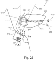
- FIG. 21 shows an alternative structure of the mirror adjustment.
- the glass adjusting drive 515 is installed with its surface 512 in such a way that the surface 512 points in the direction of the housing cap 506.
- the rotary table 512 of the glass adjusting drive 515 engages either directly or via a connecting plate 517 on the housing cap, which is rigidly connected to the mirror glass 511.
- the electrical connection of the external rearview mirror is effected via the hollow mirror base 502.
- the electrical cables for the glass adjustment drive are carried out and connected directly to the drive.
- the contacting of the mirror glass is achieved either directly via the glass adjusting motor 515 or, in the embodiment according to FIG. 9 , separate contacts are laid with their own electrical supply line.
- an external rear view mirror assembly for a motor vehicle includes a mirror base or foot provided for arrangement on the motor vehicle and a mirror head arranged on the mirror foot as well as a mirror glass accommodated in the mirror head and arranged rigidly and fixed non adjustably with respect thereto.
- a mirror base or foot provided for arrangement on the motor vehicle and a mirror head arranged on the mirror foot as well as a mirror glass accommodated in the mirror head and arranged rigidly and fixed non adjustably with respect thereto.
- European Patent No. 2 492 144 which is hereby incorporated by reference in its entirety for all purposes.
- At least one articulation is provided between the mirror head and the arrangement of the mirror foot on the motor vehicle, this articulation including a total of two articulation axes, the direction vectors of said articulation axes being independent of each other, and where the two articulation axes are associated, jointly and/or independently of each other.
- This may allow swiveling at least the mirror head from an operating position to a swung-in position and vice versa, and swinging-in at least the mirror head in and against the direction of motion, as well as adjusting an individual adjusting position of at least the mirror glass by adjusting the mirror head depending on, e.g., the seating position and the height of a driver of the motor vehicle.
- a first adjusting drive driven by an electric motor and associated to a first articulation axis of the two articulation axes and a second adjusting drive driven by an electric motor and associated to a second articulation axis of the two articulation axes.
- rear view arrangement 601 for a motor vehicle includes of a base 602 provided for the motor vehicle-side arrangement and a head 603 arranged thereon, as well as a viewing means 604, which is accommodated in the head 603 and which is rigidly and fixedly arranged relative thereto.
- At least one articulated joint 605, 606, 607 is provided between the head 603 and the motor vehicle side of the base 602.
- a first electromotive adjusting drive 610 is assigned to a first articulation axis 608 of the two articulated axes 608,
- a second electromotive adjusting drive 611 is assigned to a second articulation axis 609 of the two articulation axes 608.
- the exterior rear view arrangement 601 includes, collectively, the viewing mean 604 as at least one reflecting or mirrored surface, which can be viewed by a driver of the motor vehicle from the vehicle interior, for example, through a side window and provides insight into one or more areas of a vehicle environment including in the direction of the road from the driver's seat.
- the viewing means 604 may be a mirror glass and an electrochromic dimming of the mirror glass can be provided.
- the mirror glass 604 can be designed as an electrochromatically dimmable mirror glass.
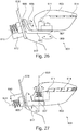
- the first joint axis 608 and the second joint axis 609 can intersect each other as shown in FIGS. 26 to 30 .
- the first joint axis 608 and the second joint axis 609 intersect at a right angle, as in the case of the embodiments shown in FIGS. 28 to 30 .
- one of the two articulated axles 608, 609 can be as shown in FIGS. 24 , 25 , 28 and 29 , and be substantially approximately horizontal when the rear view arrangement 601 is arranged on the vehicle side.
- the two electromotive adjusting drives 610, 611 are preferably controllable independently of one another.
- a housing and display device of a rearview device is disclosed in European patent No. 2738043, filed on December 3, 2012 for HOUSING AND DISPLAY DEVICE which is hereby incorporated herein by reference.
- An optical light guide for a vehicle lighting unit is disclosed in European patent No. 2947378, filed on May 22, 2014 for OPTICAL LIGHT GUIDE FOR A VEHICLE LIGHTING UNIT which is hereby incorporated herein by reference.
- a display device of a rearview device of a vehicle is disclosed in International patent application No.
- optical elements know to be used in camera modules are optical fibers, especially in form of fiber bundles and preferably in form of fiber bundles having an optical head, as described for example in US patent publication No. US 2001/0022550 A1 .
- Different methods can be used to produce such optical elements, for example as described in US patent 8,460,060, filed on January 30, 2009 for METHOD FOR CREATING A COMPLEX SURFACE ON A SUBSTRATE OF GLASS, which is hereby incorporated herein by reference.
- light sources can be installed or integrated into the camera module to increase the visibility of surrounding objects, measure distances and directions and detect dirt, such as described in US patent No. 8,031,224 , US patent application No. 62/470,658, filed on March 13, 2017 , 2016 for LIGHT EMITTING MIRROR BEZEL and US patent publication No. US 2001/0022550 A1 , which are all hereby incorporated herein by reference.
- Different heating means like heating coils, heating devices integrated into the lens holder or the bezel, or other heating elements can be used to impede condensation and icing at the surface of optical elements, as for example described in German patent application No. 102016108247.3 , US patent application No. 62/470,658 , and German patent application No. 102016107545.0, filed on April 22, 2016 for HEATING DEVICE FOR A CAMERA LENS, which are all hereby incorporated herein by reference.
- a watertight seal against weather effects, as well as against the influence of washing processes with detergents, solvents and high pressure cleaners can be used on the housing of the camera module as described in US patent application No. 13/090,127 , which is hereby incorporated herein by reference.
- the camera module can include a power harvesting system as described for example in European patent application No. 09171683.7, filed on Sept. 29, 2009 for SELF SUSTAINING REAR VIEW MIRROR, which is hereby incorporated herein by reference.
- Different types of fixings can be used to fix the camera module to the vehicle or other components, such as for example the snap-fit connection described in European patent No. 2233360, filed on March 27, 2009 for SNAP FIT CONNECTION IN A REAR VIEW MIRROR, which is hereby incorporated herein by reference.
Applications Claiming Priority (1)
| Application Number | Priority Date | Filing Date | Title |
|---|---|---|---|
| US15/607,894 US10744947B2 (en) | 2012-01-24 | 2017-05-30 | Head section for a rear view device |
Publications (2)
| Publication Number | Publication Date |
|---|---|
| EP3409537A1 true EP3409537A1 (de) | 2018-12-05 |
| EP3409537B1 EP3409537B1 (de) | 2019-07-10 |
Family
ID=62620647
Family Applications (1)
| Application Number | Title | Priority Date | Filing Date |
|---|---|---|---|
| EP18175142.1A Active EP3409537B1 (de) | 2017-05-30 | 2018-05-30 | Kopfabschnitt für eine rückblickvorrichtung |
Country Status (1)
| Country | Link |
|---|---|
| EP (1) | EP3409537B1 (de) |
Citations (46)
| Publication number | Priority date | Publication date | Assignee | Title |
|---|---|---|---|---|
| US4139269A (en) * | 1976-10-29 | 1979-02-13 | Backenkoehler Willi | Mirror with rim in groove mounting |
| US20010022550A1 (en) | 2000-01-28 | 2001-09-20 | Reitter & Schefenacker Gmbh & Co. Kg | Monitoring device for vehicles, in particular, motor vehicles |
| EP1186473A2 (de) * | 2000-09-05 | 2002-03-13 | MEKRA Lang GmbH & Co. KG | Rückspiegel, insbesondere für Kraftfahrzeuge |
| EP1328141A2 (de) | 2002-01-12 | 2003-07-16 | Schefenacker Vision Systems Germany GmbH & Co. KG | Leiterbahn aus flexiblem Material, Baueinheit mit einer solchen flexiblen Leiterbahn und Verfahren zur Herstellung einer solchen Leiterbahn |
| EP1673260A2 (de) | 2003-10-14 | 2006-06-28 | Schefenacker Vision Systems Germany GmbH & Co. KG | Reinigungsvorrichtung |
| EP2017127A1 (de) | 2007-07-19 | 2009-01-21 | Visiocorp Patents S.à.r.l. | Vorrichtung zum Anpassen der Ausrichtung eines Spiegels eines Kraftfahrzeugs |
| EP2146325A1 (de) | 2008-07-16 | 2010-01-20 | SMR PATENTS S.à.r.l. | Aufzeichnungsgerät für die Aufnahme und Bearbeitung von Bilddaten in einem Fahrzeug sowie Verfahren |
| EP2202826A1 (de) | 2008-12-23 | 2010-06-30 | SMR PATENTS S.à.r.l. | Polymerelektrolyte und Vorrichtungen damit |
| EP2233360A1 (de) | 2009-03-27 | 2010-09-29 | SMR Patents S.à.r.l. | Schnappverschluss in einem Rückspiegel |
| US7999992B2 (en) | 2005-07-01 | 2011-08-16 | Smr Patents S.A.R.L. | Charge conducting medium |
| US8031224B2 (en) | 2006-09-14 | 2011-10-04 | Smr Patents S.A.R.L. | Camera system, method for operation of a camera system and sensor device of a camera system |
| US20110254957A1 (en) | 2010-04-19 | 2011-10-20 | Smr Patents S.A.R.L. | Rear view mirror simulation |
| US20120154587A1 (en) | 2010-12-15 | 2012-06-21 | SMR Patents S.ar.I. | Camera arrangement and door handle for motor vehicle |
| DE102011103200A1 (de) | 2011-05-31 | 2012-12-06 | SMR Patents S.à.r.l. | Lichtfenster |
| DE102012107339A1 (de) * | 2011-08-10 | 2013-02-14 | SMR Patents S.à.r.l. | Außenrückblickspiegelanordnung |
| US8395514B2 (en) | 2008-06-24 | 2013-03-12 | Smr Patents S.A.R.L. | Optical system and method for detecting optical system obscuration in a vehicle |
| DE102011053999A1 (de) | 2011-09-28 | 2013-03-28 | SMR Patents S.à.r.l. | Erfassungssystem, Kraftfahrzeug und Fahrerassistenzsystem |
| US8460060B2 (en) | 2009-01-30 | 2013-06-11 | Smr Patents S.A.R.L. | Method for creating a complex surface on a substrate of glass |
| US8487633B2 (en) | 2010-01-14 | 2013-07-16 | Smr Patents S.A.R.L. | Fault detection of electric consumers in motor vehicles |
| US8537451B2 (en) | 2008-03-26 | 2013-09-17 | Smr Patents S.A.R.L. | Processes for producing electrochromic substrates and electrochromic articles made therefrom |
| DE102012104529A1 (de) | 2012-05-25 | 2013-11-28 | SMR Patents S.à.r.l. | Lichtleiteinheit |
| DE102012107834A1 (de) | 2012-08-24 | 2014-02-27 | SMR Patents S.à.r.l. | Beleuchtungseinrichtung und Rückblickeinrichtung |
| DE102012107833A1 (de) | 2012-08-24 | 2014-02-27 | SMR Patents S.à.r.l. | Beleuchtungseinrichtung und Rückblickeinrichtung |
| DE102012108488A1 (de) | 2012-09-11 | 2014-03-13 | SMR Patents S.à.r.l. | Rückblickanordnung für ein Kraftfahrzeug |
| EP2492144B1 (de) | 2011-02-23 | 2014-04-02 | SMR Patents S.à.r.l. | Aussenrückblickspiegelanordnung für ein Kraftfahrzeug |
| EP2492145B1 (de) | 2011-02-23 | 2014-04-02 | SMR Patents S.à.r.l. | Verstellbarer Aussenrückblickspiegel |
| US8740427B2 (en) | 2010-09-08 | 2014-06-03 | Smr Patents S.A.R.L. | Optimal light coupling for rear view devices |
| EP2738043A1 (de) | 2012-12-03 | 2014-06-04 | SMR Patents S.à.r.l. | Gehäuse und Anzeigeeinrichtung |
| US20140376119A1 (en) * | 2013-06-25 | 2014-12-25 | Magna Mirrors Of America, Inc. | Rearview mirror assembly for vehicle |
| DE202015104894U1 (de) | 2015-09-15 | 2015-09-25 | SMR Patents S.à.r.l. | Beleuchtungseinrichtung, Fahrzeugkomponente und Fahrzeug |
| US9181616B2 (en) | 2012-01-24 | 2015-11-10 | Smr Patents S.A.R.L. | Chromium-based reflective coating |
| EP2944866A1 (de) | 2014-05-12 | 2015-11-18 | SMR Patents S.à.r.l. | Optikeinheit, Anzeigeeinrichtung, Rückblickvorrichtung und Kraftfahrzeug damit |
| EP2947378A1 (de) | 2014-05-22 | 2015-11-25 | SMR Patents S.à.r.l. | Lichtleiter für eine Fahrzeugbeleuchtungseinheit |
| US20150358590A1 (en) | 2010-09-17 | 2015-12-10 | Smr Patents S.A.R.L. | Rear view device for a motor vehicle |
| US20160096487A1 (en) | 2014-07-25 | 2016-04-07 | Oleg Konevsky | Apparatus for light intensity adjustment |
| US20160129841A1 (en) | 2012-09-11 | 2016-05-12 | SMR Patents S.à.r.l. | Sealed mirror head |
| EP3045944A1 (de) | 2015-01-19 | 2016-07-20 | SMR Patents S.à.r.l. | Lichtleitvorrichtung |
| WO2016147154A1 (de) | 2015-03-19 | 2016-09-22 | Smr Patents S.A.R.L. | Leuchteinrichtung und verfahren zur herstellung einer leuchteinrichtung |
| US20160341393A1 (en) | 2015-01-19 | 2016-11-24 | SMR Patents S.à.r.I. | Light Guiding Device |
| US20170015802A1 (en) | 2014-03-07 | 2017-01-19 | University Of South Australia | Decorative coatings for plastic substrates |
| US20170015256A1 (en) | 2012-08-29 | 2017-01-19 | Smr Patents S.A.R.L. | Telescoping rearview assembly with camera and lens wiping system |
| EP3139711A1 (de) | 2015-09-03 | 2017-03-08 | SMR Patents S.à.r.l. | Elektronikvorrichtung und rückblickvorrichtung |
| EP3138734A1 (de) | 2015-09-03 | 2017-03-08 | SMR Patents S.à.r.l. | Lichtmodul, lichtanordnung und rückspiegelvorrichtung für ein fahrzeug |
| DE102015115555A1 (de) | 2015-09-15 | 2017-03-16 | SMR Patents S.à.r.l. | Beleuchtungseinrichtung, Rückblickvorrichtung, Fußraumvorrichtung und Fahrzeug |
| DE102016107545A1 (de) | 2016-04-22 | 2017-10-26 | SMR Patents S.à.r.l. | Heizvorrichtung für eine Kameralinse |
| DE102016108247A1 (de) | 2016-05-03 | 2017-11-09 | SMR Patents S.à.r.l. | Reinigungssystem für eine Kameralinse |
-
2018
- 2018-05-30 EP EP18175142.1A patent/EP3409537B1/de active Active
Patent Citations (58)
| Publication number | Priority date | Publication date | Assignee | Title |
|---|---|---|---|---|
| US4139269A (en) * | 1976-10-29 | 1979-02-13 | Backenkoehler Willi | Mirror with rim in groove mounting |
| US20010022550A1 (en) | 2000-01-28 | 2001-09-20 | Reitter & Schefenacker Gmbh & Co. Kg | Monitoring device for vehicles, in particular, motor vehicles |
| US6703925B2 (en) | 2000-01-28 | 2004-03-09 | Reitter & Schefenacker Gmbh & Co. Kg | Monitoring device for vehicles, in particular, motor vehicles |
| EP1186473A2 (de) * | 2000-09-05 | 2002-03-13 | MEKRA Lang GmbH & Co. KG | Rückspiegel, insbesondere für Kraftfahrzeuge |
| EP1328141A2 (de) | 2002-01-12 | 2003-07-16 | Schefenacker Vision Systems Germany GmbH & Co. KG | Leiterbahn aus flexiblem Material, Baueinheit mit einer solchen flexiblen Leiterbahn und Verfahren zur Herstellung einer solchen Leiterbahn |
| US7083311B2 (en) | 2002-01-12 | 2006-08-01 | Schefenacker Vision Systems Germany Gmbh & Co. Kg | Conductor of flexible material, component comprising such flexible conductor, and method of manufacturing such conductor |
| EP1673260A2 (de) | 2003-10-14 | 2006-06-28 | Schefenacker Vision Systems Germany GmbH & Co. KG | Reinigungsvorrichtung |
| US7999992B2 (en) | 2005-07-01 | 2011-08-16 | Smr Patents S.A.R.L. | Charge conducting medium |
| US8031224B2 (en) | 2006-09-14 | 2011-10-04 | Smr Patents S.A.R.L. | Camera system, method for operation of a camera system and sensor device of a camera system |
| EP2017127A1 (de) | 2007-07-19 | 2009-01-21 | Visiocorp Patents S.à.r.l. | Vorrichtung zum Anpassen der Ausrichtung eines Spiegels eines Kraftfahrzeugs |
| US8537451B2 (en) | 2008-03-26 | 2013-09-17 | Smr Patents S.A.R.L. | Processes for producing electrochromic substrates and electrochromic articles made therefrom |
| US8395514B2 (en) | 2008-06-24 | 2013-03-12 | Smr Patents S.A.R.L. | Optical system and method for detecting optical system obscuration in a vehicle |
| EP2146325A1 (de) | 2008-07-16 | 2010-01-20 | SMR PATENTS S.à.r.l. | Aufzeichnungsgerät für die Aufnahme und Bearbeitung von Bilddaten in einem Fahrzeug sowie Verfahren |
| US8849104B2 (en) | 2008-07-16 | 2014-09-30 | Smr Patents S.A.R.L. | Recording device and method for capturing and processing image data in a vehicle |
| EP2202826A1 (de) | 2008-12-23 | 2010-06-30 | SMR PATENTS S.à.r.l. | Polymerelektrolyte und Vorrichtungen damit |
| US8460060B2 (en) | 2009-01-30 | 2013-06-11 | Smr Patents S.A.R.L. | Method for creating a complex surface on a substrate of glass |
| EP2233360A1 (de) | 2009-03-27 | 2010-09-29 | SMR Patents S.à.r.l. | Schnappverschluss in einem Rückspiegel |
| US8487633B2 (en) | 2010-01-14 | 2013-07-16 | Smr Patents S.A.R.L. | Fault detection of electric consumers in motor vehicles |
| US9238434B2 (en) | 2010-04-19 | 2016-01-19 | Smr Patents S.A.R.L. | Rear view mirror simulation |
| US20110254957A1 (en) | 2010-04-19 | 2011-10-20 | Smr Patents S.A.R.L. | Rear view mirror simulation |
| US8740427B2 (en) | 2010-09-08 | 2014-06-03 | Smr Patents S.A.R.L. | Optimal light coupling for rear view devices |
| US20150358590A1 (en) | 2010-09-17 | 2015-12-10 | Smr Patents S.A.R.L. | Rear view device for a motor vehicle |
| US20120154587A1 (en) | 2010-12-15 | 2012-06-21 | SMR Patents S.ar.I. | Camera arrangement and door handle for motor vehicle |
| EP2492145B1 (de) | 2011-02-23 | 2014-04-02 | SMR Patents S.à.r.l. | Verstellbarer Aussenrückblickspiegel |
| EP2492144B1 (de) | 2011-02-23 | 2014-04-02 | SMR Patents S.à.r.l. | Aussenrückblickspiegelanordnung für ein Kraftfahrzeug |
| DE102011103200A1 (de) | 2011-05-31 | 2012-12-06 | SMR Patents S.à.r.l. | Lichtfenster |
| US8779911B2 (en) | 2011-08-10 | 2014-07-15 | Smr Patents S.A.R.L. | Vehicular mirror with blind spot indicator |
| DE102012107339A1 (de) * | 2011-08-10 | 2013-02-14 | SMR Patents S.à.r.l. | Außenrückblickspiegelanordnung |
| DE102011053999A1 (de) | 2011-09-28 | 2013-03-28 | SMR Patents S.à.r.l. | Erfassungssystem, Kraftfahrzeug und Fahrerassistenzsystem |
| US20170158138A1 (en) | 2012-01-24 | 2017-06-08 | SMR Patents S.à.r.l. | Reflective coatings and mirrors using same |
| US9181616B2 (en) | 2012-01-24 | 2015-11-10 | Smr Patents S.A.R.L. | Chromium-based reflective coating |
| US20160059773A1 (en) | 2012-01-24 | 2016-03-03 | Smr Patents S.A.R.L. | Coated Polymeric Substrates |
| DE102012104529A1 (de) | 2012-05-25 | 2013-11-28 | SMR Patents S.à.r.l. | Lichtleiteinheit |
| DE102012107833A1 (de) | 2012-08-24 | 2014-02-27 | SMR Patents S.à.r.l. | Beleuchtungseinrichtung und Rückblickeinrichtung |
| DE102012107834A1 (de) | 2012-08-24 | 2014-02-27 | SMR Patents S.à.r.l. | Beleuchtungseinrichtung und Rückblickeinrichtung |
| US20170015256A1 (en) | 2012-08-29 | 2017-01-19 | Smr Patents S.A.R.L. | Telescoping rearview assembly with camera and lens wiping system |
| US20160129841A1 (en) | 2012-09-11 | 2016-05-12 | SMR Patents S.à.r.l. | Sealed mirror head |
| DE102012108488A1 (de) | 2012-09-11 | 2014-03-13 | SMR Patents S.à.r.l. | Rückblickanordnung für ein Kraftfahrzeug |
| EP2738043A1 (de) | 2012-12-03 | 2014-06-04 | SMR Patents S.à.r.l. | Gehäuse und Anzeigeeinrichtung |
| US20140376119A1 (en) * | 2013-06-25 | 2014-12-25 | Magna Mirrors Of America, Inc. | Rearview mirror assembly for vehicle |
| US20170015802A1 (en) | 2014-03-07 | 2017-01-19 | University Of South Australia | Decorative coatings for plastic substrates |
| WO2015173695A2 (de) | 2014-05-12 | 2015-11-19 | Smr Patents S.A.R.L. | Anzeigevorrichtung, rückblickvorrichtung und kraftfahrzeug |
| EP2944866A1 (de) | 2014-05-12 | 2015-11-18 | SMR Patents S.à.r.l. | Optikeinheit, Anzeigeeinrichtung, Rückblickvorrichtung und Kraftfahrzeug damit |
| EP2947378A1 (de) | 2014-05-22 | 2015-11-25 | SMR Patents S.à.r.l. | Lichtleiter für eine Fahrzeugbeleuchtungseinheit |
| US20160096487A1 (en) | 2014-07-25 | 2016-04-07 | Oleg Konevsky | Apparatus for light intensity adjustment |
| US20160209000A1 (en) | 2015-01-19 | 2016-07-21 | SMR Patents S.à.r.l. | Light Guiding Device |
| US20160341393A1 (en) | 2015-01-19 | 2016-11-24 | SMR Patents S.à.r.I. | Light Guiding Device |
| EP3045944A1 (de) | 2015-01-19 | 2016-07-20 | SMR Patents S.à.r.l. | Lichtleitvorrichtung |
| DE102015104163A1 (de) | 2015-03-19 | 2016-09-22 | SMR Patents S.à.r.l. | Leuchteinrichtung und Verfahren zur Herstellung einer Leuchteinrichtung |
| WO2016147154A1 (de) | 2015-03-19 | 2016-09-22 | Smr Patents S.A.R.L. | Leuchteinrichtung und verfahren zur herstellung einer leuchteinrichtung |
| EP3139711A1 (de) | 2015-09-03 | 2017-03-08 | SMR Patents S.à.r.l. | Elektronikvorrichtung und rückblickvorrichtung |
| EP3138734A1 (de) | 2015-09-03 | 2017-03-08 | SMR Patents S.à.r.l. | Lichtmodul, lichtanordnung und rückspiegelvorrichtung für ein fahrzeug |
| US20170066379A1 (en) | 2015-09-03 | 2017-03-09 | SMR Patents S.à.r.l. | Electronic Device And Rear-View Device |
| DE102015115555A1 (de) | 2015-09-15 | 2017-03-16 | SMR Patents S.à.r.l. | Beleuchtungseinrichtung, Rückblickvorrichtung, Fußraumvorrichtung und Fahrzeug |
| EP3144183A1 (de) | 2015-09-15 | 2017-03-22 | SMR Patents S.à.r.l. | Beleuchtungseinrichtung, fahrzeugkomponente und fahrzeug |
| DE202015104894U1 (de) | 2015-09-15 | 2015-09-25 | SMR Patents S.à.r.l. | Beleuchtungseinrichtung, Fahrzeugkomponente und Fahrzeug |
| DE102016107545A1 (de) | 2016-04-22 | 2017-10-26 | SMR Patents S.à.r.l. | Heizvorrichtung für eine Kameralinse |
| DE102016108247A1 (de) | 2016-05-03 | 2017-11-09 | SMR Patents S.à.r.l. | Reinigungssystem für eine Kameralinse |
Also Published As
| Publication number | Publication date |
|---|---|
| EP3409537B1 (de) | 2019-07-10 |
Similar Documents
| Publication | Publication Date | Title |
|---|---|---|
| US10744947B2 (en) | Head section for a rear view device | |
| US20210370835A1 (en) | Rearview device with moveable head assembly | |
| US10661714B2 (en) | Rearview device with moveable head assembly and method | |
| US10759345B2 (en) | External rear view device with moveable head assembly | |
| EP3681761B1 (de) | Aussenrücksichtvorrichtung sowie fahrzeug mit einer derartigen vorrichtung | |
| EP3638543B1 (de) | Rücksichtvorrichtung mit bewegbarer kopfbaugruppe sowie fahrzeug mit einer entsprechenden vorrichtung | |
| EP3835131B1 (de) | Rückblickvorrichtung mit beweglicher kopfanordnung | |
| US20240001848A1 (en) | Rearview device with moveable head assembly and method of assembling same | |
| JP6704382B2 (ja) | 移動可能ヘッド組立体を伴う後方視界装置 | |
| US20210213882A1 (en) | Camera cradle assembly for rear view device | |
| US11220217B2 (en) | Rearview device with moveable head assembly and method of assembling same | |
| EP3480062B1 (de) | Rückblickvorrichtung mit beweglicher kopfanordnung | |
| EP3406488B1 (de) | Aussenrücksichtvorrichtung mit beweglicher kopfanordnung | |
| US11273764B2 (en) | External rearview device, external rearview device kit and vehicle | |
| US11890989B2 (en) | External rearview device, external rearview device kit and vehicle | |
| EP3409537B1 (de) | Kopfabschnitt für eine rückblickvorrichtung | |
| US20240034239A1 (en) | Rearview device with moveable head assembly and method of assembling same | |
| US11884212B2 (en) | Rearview device with moveable head assembly and vehicle therewith | |
| US11541811B2 (en) | Set of rear view assemblies and vehicle |
Legal Events
| Date | Code | Title | Description |
|---|---|---|---|
| PUAI | Public reference made under article 153(3) epc to a published international application that has entered the european phase |
Free format text: ORIGINAL CODE: 0009012 |
|
| STAA | Information on the status of an ep patent application or granted ep patent |
Free format text: STATUS: THE APPLICATION HAS BEEN PUBLISHED |
|
| AK | Designated contracting states |
Kind code of ref document: A1 Designated state(s): AL AT BE BG CH CY CZ DE DK EE ES FI FR GB GR HR HU IE IS IT LI LT LU LV MC MK MT NL NO PL PT RO RS SE SI SK SM TR |
|
| AX | Request for extension of the european patent |
Extension state: BA ME |
|
| STAA | Information on the status of an ep patent application or granted ep patent |
Free format text: STATUS: REQUEST FOR EXAMINATION WAS MADE |
|
| 17P | Request for examination filed |
Effective date: 20181130 |
|
| RBV | Designated contracting states (corrected) |
Designated state(s): AL AT BE BG CH CY CZ DE DK EE ES FI FR GB GR HR HU IE IS IT LI LT LU LV MC MK MT NL NO PL PT RO RS SE SI SK SM TR |
|
| GRAP | Despatch of communication of intention to grant a patent |
Free format text: ORIGINAL CODE: EPIDOSNIGR1 |
|
| STAA | Information on the status of an ep patent application or granted ep patent |
Free format text: STATUS: GRANT OF PATENT IS INTENDED |
|
| INTG | Intention to grant announced |
Effective date: 20190204 |
|
| GRAS | Grant fee paid |
Free format text: ORIGINAL CODE: EPIDOSNIGR3 |
|
| GRAA | (expected) grant |
Free format text: ORIGINAL CODE: 0009210 |
|
| STAA | Information on the status of an ep patent application or granted ep patent |
Free format text: STATUS: THE PATENT HAS BEEN GRANTED |
|
| AK | Designated contracting states |
Kind code of ref document: B1 Designated state(s): AL AT BE BG CH CY CZ DE DK EE ES FI FR GB GR HR HU IE IS IT LI LT LU LV MC MK MT NL NO PL PT RO RS SE SI SK SM TR |
|
| REG | Reference to a national code |
Ref country code: GB Ref legal event code: FG4D |
|
| REG | Reference to a national code |
Ref country code: CH Ref legal event code: EP Ref country code: AT Ref legal event code: REF Ref document number: 1153221 Country of ref document: AT Kind code of ref document: T Effective date: 20190715 |
|
| REG | Reference to a national code |
Ref country code: DE Ref legal event code: R096 Ref document number: 602018000238 Country of ref document: DE |
|
| REG | Reference to a national code |
Ref country code: IE Ref legal event code: FG4D |
|
| REG | Reference to a national code |
Ref country code: NL Ref legal event code: MP Effective date: 20190710 |
|
| REG | Reference to a national code |
Ref country code: LT Ref legal event code: MG4D |
|
| REG | Reference to a national code |
Ref country code: AT Ref legal event code: MK05 Ref document number: 1153221 Country of ref document: AT Kind code of ref document: T Effective date: 20190710 |
|
| PG25 | Lapsed in a contracting state [announced via postgrant information from national office to epo] |
Ref country code: NO Free format text: LAPSE BECAUSE OF FAILURE TO SUBMIT A TRANSLATION OF THE DESCRIPTION OR TO PAY THE FEE WITHIN THE PRESCRIBED TIME-LIMIT Effective date: 20191010 Ref country code: BG Free format text: LAPSE BECAUSE OF FAILURE TO SUBMIT A TRANSLATION OF THE DESCRIPTION OR TO PAY THE FEE WITHIN THE PRESCRIBED TIME-LIMIT Effective date: 20191010 Ref country code: HR Free format text: LAPSE BECAUSE OF FAILURE TO SUBMIT A TRANSLATION OF THE DESCRIPTION OR TO PAY THE FEE WITHIN THE PRESCRIBED TIME-LIMIT Effective date: 20190710 Ref country code: SE Free format text: LAPSE BECAUSE OF FAILURE TO SUBMIT A TRANSLATION OF THE DESCRIPTION OR TO PAY THE FEE WITHIN THE PRESCRIBED TIME-LIMIT Effective date: 20190710 Ref country code: FI Free format text: LAPSE BECAUSE OF FAILURE TO SUBMIT A TRANSLATION OF THE DESCRIPTION OR TO PAY THE FEE WITHIN THE PRESCRIBED TIME-LIMIT Effective date: 20190710 Ref country code: LT Free format text: LAPSE BECAUSE OF FAILURE TO SUBMIT A TRANSLATION OF THE DESCRIPTION OR TO PAY THE FEE WITHIN THE PRESCRIBED TIME-LIMIT Effective date: 20190710 Ref country code: PT Free format text: LAPSE BECAUSE OF FAILURE TO SUBMIT A TRANSLATION OF THE DESCRIPTION OR TO PAY THE FEE WITHIN THE PRESCRIBED TIME-LIMIT Effective date: 20191111 Ref country code: NL Free format text: LAPSE BECAUSE OF FAILURE TO SUBMIT A TRANSLATION OF THE DESCRIPTION OR TO PAY THE FEE WITHIN THE PRESCRIBED TIME-LIMIT Effective date: 20190710 Ref country code: AT Free format text: LAPSE BECAUSE OF FAILURE TO SUBMIT A TRANSLATION OF THE DESCRIPTION OR TO PAY THE FEE WITHIN THE PRESCRIBED TIME-LIMIT Effective date: 20190710 |
|
| PG25 | Lapsed in a contracting state [announced via postgrant information from national office to epo] |
Ref country code: ES Free format text: LAPSE BECAUSE OF FAILURE TO SUBMIT A TRANSLATION OF THE DESCRIPTION OR TO PAY THE FEE WITHIN THE PRESCRIBED TIME-LIMIT Effective date: 20190710 Ref country code: AL Free format text: LAPSE BECAUSE OF FAILURE TO SUBMIT A TRANSLATION OF THE DESCRIPTION OR TO PAY THE FEE WITHIN THE PRESCRIBED TIME-LIMIT Effective date: 20190710 Ref country code: LV Free format text: LAPSE BECAUSE OF FAILURE TO SUBMIT A TRANSLATION OF THE DESCRIPTION OR TO PAY THE FEE WITHIN THE PRESCRIBED TIME-LIMIT Effective date: 20190710 Ref country code: RS Free format text: LAPSE BECAUSE OF FAILURE TO SUBMIT A TRANSLATION OF THE DESCRIPTION OR TO PAY THE FEE WITHIN THE PRESCRIBED TIME-LIMIT Effective date: 20190710 Ref country code: IS Free format text: LAPSE BECAUSE OF FAILURE TO SUBMIT A TRANSLATION OF THE DESCRIPTION OR TO PAY THE FEE WITHIN THE PRESCRIBED TIME-LIMIT Effective date: 20191110 Ref country code: GR Free format text: LAPSE BECAUSE OF FAILURE TO SUBMIT A TRANSLATION OF THE DESCRIPTION OR TO PAY THE FEE WITHIN THE PRESCRIBED TIME-LIMIT Effective date: 20191011 |
|
| REG | Reference to a national code |
Ref country code: DE Ref legal event code: R084 Ref document number: 602018000238 Country of ref document: DE |
|
| PG25 | Lapsed in a contracting state [announced via postgrant information from national office to epo] |
Ref country code: TR Free format text: LAPSE BECAUSE OF FAILURE TO SUBMIT A TRANSLATION OF THE DESCRIPTION OR TO PAY THE FEE WITHIN THE PRESCRIBED TIME-LIMIT Effective date: 20190710 |
|
| PG25 | Lapsed in a contracting state [announced via postgrant information from national office to epo] |
Ref country code: RO Free format text: LAPSE BECAUSE OF FAILURE TO SUBMIT A TRANSLATION OF THE DESCRIPTION OR TO PAY THE FEE WITHIN THE PRESCRIBED TIME-LIMIT Effective date: 20190710 Ref country code: PL Free format text: LAPSE BECAUSE OF FAILURE TO SUBMIT A TRANSLATION OF THE DESCRIPTION OR TO PAY THE FEE WITHIN THE PRESCRIBED TIME-LIMIT Effective date: 20190710 Ref country code: EE Free format text: LAPSE BECAUSE OF FAILURE TO SUBMIT A TRANSLATION OF THE DESCRIPTION OR TO PAY THE FEE WITHIN THE PRESCRIBED TIME-LIMIT Effective date: 20190710 Ref country code: IT Free format text: LAPSE BECAUSE OF FAILURE TO SUBMIT A TRANSLATION OF THE DESCRIPTION OR TO PAY THE FEE WITHIN THE PRESCRIBED TIME-LIMIT Effective date: 20190710 Ref country code: DK Free format text: LAPSE BECAUSE OF FAILURE TO SUBMIT A TRANSLATION OF THE DESCRIPTION OR TO PAY THE FEE WITHIN THE PRESCRIBED TIME-LIMIT Effective date: 20190710 |
|
| PG25 | Lapsed in a contracting state [announced via postgrant information from national office to epo] |
Ref country code: SK Free format text: LAPSE BECAUSE OF FAILURE TO SUBMIT A TRANSLATION OF THE DESCRIPTION OR TO PAY THE FEE WITHIN THE PRESCRIBED TIME-LIMIT Effective date: 20190710 Ref country code: IS Free format text: LAPSE BECAUSE OF FAILURE TO SUBMIT A TRANSLATION OF THE DESCRIPTION OR TO PAY THE FEE WITHIN THE PRESCRIBED TIME-LIMIT Effective date: 20200224 Ref country code: CZ Free format text: LAPSE BECAUSE OF FAILURE TO SUBMIT A TRANSLATION OF THE DESCRIPTION OR TO PAY THE FEE WITHIN THE PRESCRIBED TIME-LIMIT Effective date: 20190710 Ref country code: SM Free format text: LAPSE BECAUSE OF FAILURE TO SUBMIT A TRANSLATION OF THE DESCRIPTION OR TO PAY THE FEE WITHIN THE PRESCRIBED TIME-LIMIT Effective date: 20190710 |
|
| REG | Reference to a national code |
Ref country code: DE Ref legal event code: R097 Ref document number: 602018000238 Country of ref document: DE |
|
| PLBE | No opposition filed within time limit |
Free format text: ORIGINAL CODE: 0009261 |
|
| STAA | Information on the status of an ep patent application or granted ep patent |
Free format text: STATUS: NO OPPOSITION FILED WITHIN TIME LIMIT |
|
| PG2D | Information on lapse in contracting state deleted |
Ref country code: IS |
|
| 26N | No opposition filed |
Effective date: 20200603 |
|
| PG25 | Lapsed in a contracting state [announced via postgrant information from national office to epo] |
Ref country code: MC Free format text: LAPSE BECAUSE OF FAILURE TO SUBMIT A TRANSLATION OF THE DESCRIPTION OR TO PAY THE FEE WITHIN THE PRESCRIBED TIME-LIMIT Effective date: 20190710 |
|
| REG | Reference to a national code |
Ref country code: BE Ref legal event code: MM Effective date: 20200531 |
|
| PG25 | Lapsed in a contracting state [announced via postgrant information from national office to epo] |
Ref country code: LU Free format text: LAPSE BECAUSE OF NON-PAYMENT OF DUE FEES Effective date: 20200530 |
|
| PG25 | Lapsed in a contracting state [announced via postgrant information from national office to epo] |
Ref country code: IE Free format text: LAPSE BECAUSE OF NON-PAYMENT OF DUE FEES Effective date: 20200530 |
|
| PG25 | Lapsed in a contracting state [announced via postgrant information from national office to epo] |
Ref country code: BE Free format text: LAPSE BECAUSE OF NON-PAYMENT OF DUE FEES Effective date: 20200531 |
|
| REG | Reference to a national code |
Ref country code: CH Ref legal event code: PL |
|
| PG25 | Lapsed in a contracting state [announced via postgrant information from national office to epo] |
Ref country code: LI Free format text: LAPSE BECAUSE OF NON-PAYMENT OF DUE FEES Effective date: 20210531 Ref country code: CH Free format text: LAPSE BECAUSE OF NON-PAYMENT OF DUE FEES Effective date: 20210531 |
|
| PG25 | Lapsed in a contracting state [announced via postgrant information from national office to epo] |
Ref country code: MT Free format text: LAPSE BECAUSE OF FAILURE TO SUBMIT A TRANSLATION OF THE DESCRIPTION OR TO PAY THE FEE WITHIN THE PRESCRIBED TIME-LIMIT Effective date: 20190710 Ref country code: CY Free format text: LAPSE BECAUSE OF FAILURE TO SUBMIT A TRANSLATION OF THE DESCRIPTION OR TO PAY THE FEE WITHIN THE PRESCRIBED TIME-LIMIT Effective date: 20190710 |
|
| PG25 | Lapsed in a contracting state [announced via postgrant information from national office to epo] |
Ref country code: MK Free format text: LAPSE BECAUSE OF FAILURE TO SUBMIT A TRANSLATION OF THE DESCRIPTION OR TO PAY THE FEE WITHIN THE PRESCRIBED TIME-LIMIT Effective date: 20190710 |
|
| P01 | Opt-out of the competence of the unified patent court (upc) registered |
Effective date: 20230616 |
|
| PGFP | Annual fee paid to national office [announced via postgrant information from national office to epo] |
Ref country code: FR Payment date: 20230517 Year of fee payment: 6 Ref country code: DE Payment date: 20230519 Year of fee payment: 6 |
|
| PG25 | Lapsed in a contracting state [announced via postgrant information from national office to epo] |
Ref country code: SI Free format text: LAPSE BECAUSE OF FAILURE TO SUBMIT A TRANSLATION OF THE DESCRIPTION OR TO PAY THE FEE WITHIN THE PRESCRIBED TIME-LIMIT Effective date: 20190710 |
|
| PGFP | Annual fee paid to national office [announced via postgrant information from national office to epo] |
Ref country code: GB Payment date: 20230522 Year of fee payment: 6 |