EP3409342B1 - Filtrierungsmodul mit zyklon zur luftreinigung - Google Patents
Filtrierungsmodul mit zyklon zur luftreinigung Download PDFInfo
- Publication number
- EP3409342B1 EP3409342B1 EP18170566.6A EP18170566A EP3409342B1 EP 3409342 B1 EP3409342 B1 EP 3409342B1 EP 18170566 A EP18170566 A EP 18170566A EP 3409342 B1 EP3409342 B1 EP 3409342B1
- Authority
- EP
- European Patent Office
- Prior art keywords
- water tank
- contaminated air
- cleaning
- air inlet
- cyclone
- Prior art date
- Legal status (The legal status is an assumption and is not a legal conclusion. Google has not performed a legal analysis and makes no representation as to the accuracy of the status listed.)
- Active
Links
Images



Classifications
-
- B—PERFORMING OPERATIONS; TRANSPORTING
- B01—PHYSICAL OR CHEMICAL PROCESSES OR APPARATUS IN GENERAL
- B01D—SEPARATION
- B01D50/00—Combinations of methods or devices for separating particles from gases or vapours
- B01D50/40—Combinations of devices covered by groups B01D45/00 and B01D47/00
-
- B—PERFORMING OPERATIONS; TRANSPORTING
- B01—PHYSICAL OR CHEMICAL PROCESSES OR APPARATUS IN GENERAL
- B01D—SEPARATION
- B01D45/00—Separating dispersed particles from gases or vapours by gravity, inertia, or centrifugal forces
- B01D45/12—Separating dispersed particles from gases or vapours by gravity, inertia, or centrifugal forces by centrifugal forces
-
- B—PERFORMING OPERATIONS; TRANSPORTING
- B01—PHYSICAL OR CHEMICAL PROCESSES OR APPARATUS IN GENERAL
- B01D—SEPARATION
- B01D45/00—Separating dispersed particles from gases or vapours by gravity, inertia, or centrifugal forces
- B01D45/12—Separating dispersed particles from gases or vapours by gravity, inertia, or centrifugal forces by centrifugal forces
- B01D45/16—Separating dispersed particles from gases or vapours by gravity, inertia, or centrifugal forces by centrifugal forces generated by the winding course of the gas stream, the centrifugal forces being generated solely or partly by mechanical means, e.g. fixed swirl vanes
-
- B—PERFORMING OPERATIONS; TRANSPORTING
- B01—PHYSICAL OR CHEMICAL PROCESSES OR APPARATUS IN GENERAL
- B01D—SEPARATION
- B01D47/00—Separating dispersed particles from gases, air or vapours by liquid as separating agent
-
- B—PERFORMING OPERATIONS; TRANSPORTING
- B01—PHYSICAL OR CHEMICAL PROCESSES OR APPARATUS IN GENERAL
- B01D—SEPARATION
- B01D47/00—Separating dispersed particles from gases, air or vapours by liquid as separating agent
- B01D47/06—Spray cleaning
-
- B—PERFORMING OPERATIONS; TRANSPORTING
- B04—CENTRIFUGAL APPARATUS OR MACHINES FOR CARRYING-OUT PHYSICAL OR CHEMICAL PROCESSES
- B04C—APPARATUS USING FREE VORTEX FLOW, e.g. CYCLONES
- B04C5/00—Apparatus in which the axial direction of the vortex is reversed
- B04C5/08—Vortex chamber constructions
-
- B—PERFORMING OPERATIONS; TRANSPORTING
- B04—CENTRIFUGAL APPARATUS OR MACHINES FOR CARRYING-OUT PHYSICAL OR CHEMICAL PROCESSES
- B04C—APPARATUS USING FREE VORTEX FLOW, e.g. CYCLONES
- B04C9/00—Combinations with other devices, e.g. fans, expansion chambers, diffusors, water locks
-
- A—HUMAN NECESSITIES
- A47—FURNITURE; DOMESTIC ARTICLES OR APPLIANCES; COFFEE MILLS; SPICE MILLS; SUCTION CLEANERS IN GENERAL
- A47L—DOMESTIC WASHING OR CLEANING; SUCTION CLEANERS IN GENERAL
- A47L9/00—Details or accessories of suction cleaners, e.g. mechanical means for controlling the suction or for effecting pulsating action; Storing devices specially adapted to suction cleaners or parts thereof; Carrying-vehicles specially adapted for suction cleaners
- A47L9/10—Filters; Dust separators; Dust removal; Automatic exchange of filters
- A47L9/16—Arrangement or disposition of cyclones or other devices with centrifugal action
- A47L9/1608—Cyclonic chamber constructions
-
- B—PERFORMING OPERATIONS; TRANSPORTING
- B01—PHYSICAL OR CHEMICAL PROCESSES OR APPARATUS IN GENERAL
- B01D—SEPARATION
- B01D2221/00—Applications of separation devices
- B01D2221/02—Small separation devices for domestic application, e.g. for canteens, industrial kitchen, washing machines
-
- B—PERFORMING OPERATIONS; TRANSPORTING
- B01—PHYSICAL OR CHEMICAL PROCESSES OR APPARATUS IN GENERAL
- B01D—SEPARATION
- B01D2247/00—Details relating to the separation of dispersed particles from gases, air or vapours by liquid as separating agent
- B01D2247/04—Regenerating the washing fluid
-
- B—PERFORMING OPERATIONS; TRANSPORTING
- B01—PHYSICAL OR CHEMICAL PROCESSES OR APPARATUS IN GENERAL
- B01D—SEPARATION
- B01D2247/00—Details relating to the separation of dispersed particles from gases, air or vapours by liquid as separating agent
- B01D2247/10—Means for removing the washing fluid dispersed in the gas or vapours
- B01D2247/101—Means for removing the washing fluid dispersed in the gas or vapours using a cyclone
-
- B—PERFORMING OPERATIONS; TRANSPORTING
- B01—PHYSICAL OR CHEMICAL PROCESSES OR APPARATUS IN GENERAL
- B01D—SEPARATION
- B01D2247/00—Details relating to the separation of dispersed particles from gases, air or vapours by liquid as separating agent
- B01D2247/10—Means for removing the washing fluid dispersed in the gas or vapours
- B01D2247/107—Means for removing the washing fluid dispersed in the gas or vapours using an unstructured demister, e.g. a wire mesh demister
-
- B—PERFORMING OPERATIONS; TRANSPORTING
- B01—PHYSICAL OR CHEMICAL PROCESSES OR APPARATUS IN GENERAL
- B01D—SEPARATION
- B01D47/00—Separating dispersed particles from gases, air or vapours by liquid as separating agent
- B01D47/10—Venturi scrubbers
-
- B—PERFORMING OPERATIONS; TRANSPORTING
- B04—CENTRIFUGAL APPARATUS OR MACHINES FOR CARRYING-OUT PHYSICAL OR CHEMICAL PROCESSES
- B04C—APPARATUS USING FREE VORTEX FLOW, e.g. CYCLONES
- B04C11/00—Accessories, e.g. safety or control devices, not otherwise provided for, e.g. regulators, valves in inlet or overflow ducting
-
- B—PERFORMING OPERATIONS; TRANSPORTING
- B04—CENTRIFUGAL APPARATUS OR MACHINES FOR CARRYING-OUT PHYSICAL OR CHEMICAL PROCESSES
- B04C—APPARATUS USING FREE VORTEX FLOW, e.g. CYCLONES
- B04C9/00—Combinations with other devices, e.g. fans, expansion chambers, diffusors, water locks
- B04C2009/008—Combinations with other devices, e.g. fans, expansion chambers, diffusors, water locks with injection or suction of gas or liquid into the cyclone
-
- B—PERFORMING OPERATIONS; TRANSPORTING
- B04—CENTRIFUGAL APPARATUS OR MACHINES FOR CARRYING-OUT PHYSICAL OR CHEMICAL PROCESSES
- B04C—APPARATUS USING FREE VORTEX FLOW, e.g. CYCLONES
- B04C5/00—Apparatus in which the axial direction of the vortex is reversed
- B04C5/02—Construction of inlets by which the vortex flow is generated, e.g. tangential admission, the fluid flow being forced to follow a downward path by spirally wound bulkheads, or with slightly downwardly-directed tangential admission
- B04C5/04—Tangential inlets
-
- B—PERFORMING OPERATIONS; TRANSPORTING
- B04—CENTRIFUGAL APPARATUS OR MACHINES FOR CARRYING-OUT PHYSICAL OR CHEMICAL PROCESSES
- B04C—APPARATUS USING FREE VORTEX FLOW, e.g. CYCLONES
- B04C5/00—Apparatus in which the axial direction of the vortex is reversed
- B04C5/12—Construction of the overflow ducting, e.g. diffusing or spiral exits
- B04C5/13—Construction of the overflow ducting, e.g. diffusing or spiral exits formed as a vortex finder and extending into the vortex chamber; Discharge from vortex finder otherwise than at the top of the cyclone; Devices for controlling the overflow
Definitions
- the present disclosure relates to an filtering module. More particularly, the present disclosure relates to a filtering module having a cyclone in which contaminated air containing foreign materials, such as oil and the like, is in contact with cleaning water or vapor so as to be cleaned.
- the foreign materials, such as oil and the like are suspended in a water tank so as to be separated and discharged.
- the water received in the water tank is circulated and is re-supplied as the cleaning water.
- a hood for air cleaning that forcedly sucks smells and heat generated during cooking and discharges the smells and heat to the outside is mounted over a cooking appliance such as a gas stove.
- cabinets are typically installed at an upper portion of a wall, and the gas stove is placed on a lower portion of the wall.
- an exhaust case in which an exhaust fan is mounted, is installed over the gas stove.
- an exhaust pipe is fixed to an upper end of the exhaust case, and a flexible exhaust pipe is inserted into a vent.
- the hood for air-cleaning according to the related art has problems that it requires a large installation space, and it is not aesthetically pleasing.
- a downdraft type air cleaning apparatus includes a fan motor, induces contaminated air generated from the gas stove into a downward direction of the gas stove, filters the induced contaminated air, and then discharges the filtered air.
- the downdraft type air cleaning apparatus has a problem that it may not efficiently separate foreign materials, such as oil and the like contained in the contaminated air, from the contaminated air.
- the downdraft type air cleaning apparatus has a problem that maintenance cost is increased because a cleaning filter should periodically be changed.
- the downdraft type air cleaning apparatus has a problem that it is cumbersome to use and maintain since periodic cleaning and maintenance are required.
- US 3 853 505 A relates to a process and apparatus for the removal of haze-forming constituents from wood veneer dryer effluent by condensing the haze-forming constituents, agglomerating the condensed constituents and removing them from the effluent.
- CN 2 401 258 Y relates to an oil fume purifier comprising a cyclone separator having a plurality of water fog spray heads which are arranged in a purification chamber and which are in communication with an outlet of a water reservoir via pipes.
- the cyclone separator separates oil fume from the water fog and accumulates it at the bottom of the cyclone separator, from where it is exhausted by purified smoke through a central pipe.
- CN 2 447 045 Y relates to a purifying equipment comprising a fan, a case for collecting oil fume, e.g. from a cooking stove, and a purification/recovery mechanism having a cyclone in communication with the case via a pipe for guiding the oil fume to the cyclone.
- the purification/recovery mechanism further comprises a water tank and water-spraying nozzle which is arranged inside the cyclone to spray water to the inner walls of the cyclone thereby purifying the oil fume.
- US 3 131 237 A relates to a gas scrubbing apparatus comprising a vertical gas conduit, means to flow gases to be scrubbed upwardly through said conduit, throat forming means extending inwardly from the walls of the conduit and presenting an upwardly facing surface for restricting the upward flow of gases in said conduit and means for flowing scrubbing liquid onto said surface comprising a liquid supply conduit having an opening into said gas conduit. Furthermore, the apparatus includes a plurality of spaced nozzles and means for passing a heating fluid through said nozzles.
- WO 2016/177652 A1 relates to an exhaust-gas aftertreatment device for exhaust gas of a small combustion plant, having an agglomerator and a centrifugal separator which is positioned downstream of the agglomerator such that the exhaust gas flowing through the agglomerator flows entirely into the centrifugal separator.
- the centrifugal separator has an exhaust-gas recirculation device by way of which a part of the exhaust gas, after flowing through the centrifugal separator, can be conducted to the inlet region of the centrifugal separator again.
- US 7 401 599 B2 relates to a vapor-liquid separator comprising a cylindrical separator main body, an introducing part for introducing the vapor-liquid mixed fluid into the separator main body in the tangential direction, a liquid discharging part for discharging a separated liquid, a gas exhausting part for exhausting the separated gas, a storing part for storing a liquid passed through the liquid discharging part, a stored-liquid discharging part provided in the storing part to discharge a stored liquid and a communicating part for communicating the storing part with an upstream side of a vapor-liquid separation region of the separator main body and/or the introducing part.
- JP 2008 038713 A relates to a separator having a cylindrical separator body, an introducing part introducing a gas-liquid mixture in a tangential direction inside the separator body, a liquid discharge part for discharging the separated liquid and a gas exhaust part exhausting the separated gas. Furthermore, the separator comprises a storage part for storing the liquid discharged from the liquid discharge part, a storage liquid discharge part arranged in the storage part for discharging the stored liquid and a baffle part arranged in the storage part for restraining the backflow of the liquid stored in the storage part to the liquid discharge part.
- an inclined cyclone has a contaminated air inlet part into which contaminated air and cleaning water or vapor are introduced. Accordingly, the contaminated air may come into contact with the cleaning water or vapor, and foreign materials such as oil and the like contained in the contaminated air may be efficiently separated from the contaminated air by a wide contact area and flow by centrifugal force.
- the cyclone includes a fluid circulating part. Accordingly, maintenance cost may be reduced since the foreign materials are removed from the cleaning water or vapor, thereby cleaning the contaminated air to be again circulated as the cleaning water or vapor,
- the fluid circulating part may include a heater to heat the cleaning water or, alternatively, includes a heater to heat the vapor to a temperature higher than the room temperature. Accordingly, it is possible to prevent the foreign materials containing oil from being deposited or fixed on an inner wall of the cyclone, and the filtering module having the cyclone may be automatically cleaned by a flow of the cleaning water or vapor.
- FIG. 1 is a view schematically showing a basic concept of a filtering module according to the present disclosure.
- a filtering module 100 includes a cyclone 110, a water tank 120, and a fluid circulating part 130.
- the cyclone 110 is provide to increase a contact area between contaminated air and cleaning water that cleans the contaminated air, and to efficiently separate out foreign materials such as oil and the like contained in the contaminated air using centrifugal force.
- the cyclone 110 includes a contaminated air inlet part 111 into which the contaminated air containing the foreign materials such as oil and the like and the cleaning water or vapor are each introduced, and a cleaned air outlet part 112 through which cleaned air is discharged.
- the water tank 120 is provided to collect the foreign materials such as oil and the like separated from the contaminated air, to discharge the collected foreign materials (shown by an alternated long and short dash line arrow), and to again provide the cleaning water or vapor to the contaminated air inlet part 111. To this end, a fluid is pre-stored in the water tank 120.
- the contaminated air is cleaned by being in contact with the cleaning water or vapor, and the cleaning water or vapor containing the foreign materials such as oil and the like is introduced into the water tank 120.
- the cleaning water or vapor is mixed with the pre-stored fluid.
- the mixed water obtained accordingly is stored in the water tank 120.
- the foreign materials contained in the cleaning water or vapor are suspended on a surface of the water by a specific gravity difference with the pre-stored fluid.
- the foreign materials suspended in the water tank 120 may be separated and discharged, and the water in a lower portion of the water tank 120 may be recycled.
- the fluid circulating part 130 is provided to supply the cleaning water or vapor to the water tank 120 from the contaminated air inlet part 111 of the cyclone 110 by using the mixed water.
- the cleaning water or vapor is provided to the contaminated air inlet part 111 at room temperature or a temperature higher than room temperature.
- a solid line arrow shows a flow of air
- a dotted line arrow shows a flow of cleaning water or vapor.
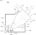
- FIG. 2 is a view schematically showing a filtering module according to a first exemplary embodiment of the present disclosure.
- a filtering module 1000 includes a cyclone 1100, a water tank 1200, and a fluid circulating part 1300.
- the cyclone 1100 may include a contaminated air inlet part 1110, a cleaned air outlet part 1120, and a body part 1130, and may be detachably coupled to the water tank 1200.
- the body part 1130 includes a cylindrical body 1131, a conical body 1132 having a truncated lower end, and a discharging part 1133.
- the conical body 1132 extends in a downward direction of the cylindrical body 1131, and the discharging part 1133 extends in a downward direction of the conical body 1132.
- the cylindrical body 1131, the conical body 1132, and the discharging part 1133 are formed integrally with each other.
- the contaminated air inlet part 1110 and the cleaned air outlet part 1120 are connected to the cylindrical body 1131 so as to be in communication with each other.
- the contaminated air inlet part 1110 may be formed so that the contaminated air is introduced in a side direction of an upper end portion of the cylindrical body 1131, and the cleaned air outlet part 1120 may be formed in the upper end portion of the cylindrical body 1131 so that the cleaned air is discharged in an axial direction (a Z direction in FIG. 2 ) of the cylindrical body 1131.
- the contaminated air inlet part 1110 and the cleaned air outlet part 1120 are disposed in a direction orthogonal to each other.
- the cleaned air outlet part 1120 has an extension part 1121 formed to extend below the cylindrical body 1131, and the cleaned air is discharged to the outside through the extension part 1121.
- This configuration is provided to bring the contaminated air introduced through the contaminated air inlet part 1110 into contact with the cleaning water, to separate the foreign materials contained in the contaminated air while the contaminated air flows in the cylindrical body 1131, and to then discharge only the cleaned air.
- the extension part 1121 is disposed to extend below the cylindrical body 1131.
- the body part 1130 is coupled to the water tank 1200 to be inclined as indicated by ⁇ in FIG. 2 . Accordingly, the cylindrical body 1131 and the conical body 1132 are disposed to be inclined about a central axis at which the cyclone 1100 is mounted.
- the conical body 1132 is connected to the cylindrical body 1131, and causes the cleaning water flowing in the conical body 1132 to flow toward the discharging part 1133.
- the conical body 1132 has an inner diameter which is gradually decreased from the cylindrical body 1131 to the discharging part 1133.
- the discharging part 1133 is provided to supply the cleaning water flowing through the conical body 1132 to the water tank 1200.
- a discharging slit 1133a is formed in the discharging part 1133 so as to easily discharge the foreign materials such as oil and the like contained in the cleaning water.
- the discharging part 1133 is positioned below the surface of water of the pre-stored fluid stored in the water tank 1200 to be in contact with the fluid pre-stored in the water tank 1200.
- the fluid circulating part 1300 includes a pump 1310, a heater 1320, and a connection pipe 1330.
- the pump 1310 is provided to produce a flow force for supplying the mixed water, in which the fluid pre-stored in the water tank 1200 and the cleaning water are mixed, to the contaminated air inlet part 1110.
- the heater 1320 is provided to increase a temperature of the mixed water supplied by the pump 1310 and to supply the mixed water as the cleaning water.
- the temperature of the mixed water may be adjusted and an occurrence of vapor may also be adjusted by adjusting a heating time of the heater 1320.
- the cleaning water Since the cleaning water is supplied at room temperature or a temperature higher than the room temperature, it prevents the oil from being coagulated or deposited on the inner wall of the cyclone 1100, as described above, thereby making it possible to automatically clean the inner wall of the cyclone 1100.
- connection pipe 1330 interconnects the water tank 1200, the pump 1310, the heater 1320, and the contaminated air inlet part 1110.
- the fluid circulating part 1300 may include a temperature sensor 1340 that measures the temperature of the cleaning water which is discharged from the heater 1320.
- the temperature sensor 1340 may be provided at the contaminated air inlet part 1110 so as to maintain a constant temperature of the cleaning water supplied to the contaminated air inlet part 1110.
- the temperature sensor 1340 may be mounted on the connection pipe which is adjacent to the contaminated air inlet part 1110.
- FIG. 3 is a view schematically showing a filtering module according to a second exemplary embodiment of the present disclosure.
- a filtering module 2000 is different from the filtering module 1000 shown in FIG. 2 only in a position of the heater.
- the filtering module 2000 includes a cyclone 2100, a water tank 2200, and a fluid circulating part 2300.
- the cyclone 2100 includes a contaminated air inlet part 2110, a cleaned air outlet part 2120, and a body part 2130.
- the fluid circulating part 2300 includes a pump 2310, a heater 2320, and a connection pipe 2330.
- the heater 2320 is mounted in the water tank 2200, and the fluid pre-stored in the water tank 2200 is heated by heat exchange with the heater 2320.
- a filtering module 3000 is different from the filtering module 1000 shown in FIG. 2 only in the presence or absence of the pump.
- the contaminated air is in contact with the cleaning water or vapor through the inclined cyclone, and the foreign materials such as oil and the like contained in the contaminated air are efficiently separated from the contaminated air by a flow by a wide contact area and centrifugal force, it is possible to obtain the cyclone having the improved cleaning performance and the filtering module having the same.
- the foreign materials such as oil and the like are removed from the cleaning water or vapor, thereby cleaning the contaminated air to be circulated as the cleaning water or vapor, so that it is possible to reduce the maintenance cost.
- the contaminated air is cleaned using the cleaning water or vapor of the room temperature or the temperature higher than the room temperature, it is possible to prevent the foreign materials containing oil from being deposited or fixed on the inner wall of the cyclone.
- the filtering module having the cyclone is automatically cleaned by the flow of the cleaning water or vapor, it is possible to obtain the cyclone for air-cleaning having improved facilities of use and the filtering module having the same.
Landscapes
- Chemical & Material Sciences (AREA)
- Chemical Kinetics & Catalysis (AREA)
- Cyclones (AREA)
Claims (8)
- Luftfiltrierungsmodul (100; 1000; 2000; 3000; 4000), das aufweist:einen Zyklon (110; 1100; 2100; 3100; 4100), der aufweist:eine Einlasskomponente für verunreinigte Luft (111; 1110; 2110; 3110; 4110), in die von außen kommende verunreinigte Luft und Reinigungswasser zum Reinigen der verunreinigten Luft eingeleitet werden; undeine Auslasskomponente der gereinigten Luft (112; 1120; 2120; 3120; 4120), durch die Luft abgegeben wird, nachdem sie gereinigt wurde, indem das Reinigungswasser in Kontakt mit der verunreinigten Luft gebracht wird;einen Wassertank (120; 1200; 2200; 3200; 4200; 5200), der mit dem Zyklon (110; 1100; 2100; 3100; 4100) gekoppelt ist, wobei der Wassertank (120; 1200; 2200; 3200; 4200; 5200) konfiguriert ist, das Reinigungswasser aus dem Zyklon (110; 1100; 2100; 3100; 4100) aufzunehmen und das Reinigungswasser aufzubewahren; undeine Fluidzirkulationskomponente (130; 1300; 2300; 3300; 4300), die konfiguriert ist, das im Wassertank (120; 1200; 2200; 3200; 4200; 5200) aufbewahrte Reinigungswasser der Einlasskomponente für verunreinigte Luft (111; 1110; 2110; 3110; 4110) bereitzustellen,wobei eine Mittelachse des Zyklons (110; 1100; 2100; 3100; 4100) in einem Neigungswinkel bezüglich des Wassertanks (120; 1200; 2200; 3200; 4200; 5200) geneigt ist,dadurch gekennzeichnet, dass der Wassertank (120; 1200; 2200; 3200; 4200; 5200) weiterhin aufweist:eine Nutkomponente (5210), die konfiguriert ist, eine Seite des Zyklons (1100) aufzunehmen und den Zyklon (1100) im Neigungswinkel zu halten; undeine Fremdmaterial-Ausgabekomponente (5220), die sich an einer Position befindet, die der Fläche des Reinigungswassers entspricht, das im Wassertank (120; 1200; 2200; 3200; 4200; 5200) aufbewahrt ist, wobei die Fremdmaterial-Ausgabekomponente (5220) geöffnet und geschlossen werden kann.
- Luftfiltrierungsmodul nach Anspruch 1, wobei der Zyklon (1100) weiterhin aufweist:einen zylindrischen Körper (1131), der die Einlasskomponente für verunreinigte Luft (1110) und die Auslasskomponente der gereinigten Luft (1120) aufweist, wobei die Einlasskomponente für verunreinigte Luft (1110) und die Auslasskomponente der gereinigten Luft (1120) miteinander in Austausch stehen;einen konischen Körper (1132), der vom zylindrischen Körper (1131) in einer Richtung des zylindrischen Körpers (1131) nach unten verläuft; undeine Ausgabekomponente (1133), die vom konischen Körper (1132) in einer Richtung des konischen Körpers (1132) nach unten verläuft;wobei die Einlasskomponente für verunreinigte Luft (1110) sich an einem oberen Endbereich einer Seite des zylindrischen Körpers (1131) befindet, wobei die Einlasskomponente für verunreinigte Luft (1110) angeordnet ist, sodass die verunreinigte Luft in einer seitlichen Richtung des zylindrischen Körpers (1131) eingeleitet wird,wobei sich die Auslasskomponente der gereinigten Luft (1120) am oberen Endbereich des zylindrischen Körpers (1131) befindet, wobei die Auslasskomponente der gereinigten Luft (1120) angeordnet ist, sodass die gereinigte Luft in einer axialen Richtung des zylindrischen Körpers (1131) ausgegeben wird, undwobei die Auslasskomponente der gereinigten Luft (1120) in einer Richtung senkrecht zur Einlasskomponente für verunreinigte Luft (1110) angeordnet ist.
- Luftfiltrierungsmodul nach Anspruch 2, wobei die Auslasskomponente der gereinigten Luft (1120) eine Erweiterungskomponente (1121) aufweist, die unter dem zylindrischen Körper (1131) verläuft, und
wobei die gereinigte Luft über die Erweiterungskomponente (1121) ausgegeben wird, wobei ein unteres Ende der Fremdmaterial-Ausgabekomponente (5520) sich unter einer Fläche des Reinigungswassers befindet, das im Wassertank (1200) aufbewahrt ist, und wobei die Fremdmaterial-Ausgabekomponente (5520) wenigstens einen Ausgabeschlitz (1133a) aufweist. - Luftfiltrierungsmodul nach Anspruch 1, wobei die Fluidzirkulationskomponente aufweist:eine Pumpe (1310; 2310), die konfiguriert ist, das im Wassertank aufbewahrte Reinigungswasser der Einlasskomponente für verunreinigte Luft (1110; 2110) zuzuleiten;eine Heizung (1320; 2320; 3310), die konfiguriert ist, eine Temperatur des durch die Pumpe (1310; 2310) zugeleiteten Reinigungswassers zu erhöhen, um dadurch das Reinigungswasser der Einlasskomponente für verunreinigte Luft (1110; 2110) mit höherer Temperatur zuzuleiten, undeine Verbindungsleitung (1330; 2330; 3320), die den Wassertank (1200; 2200; 3200), die Pumpe (1310; 2310), die Heizung (1320; 2320; 3310) und die Einlasskomponente für verunreinigte Luft (1110; 2110; 3110) miteinander verbindet,wobei die Fluidzirkulationskomponente weiterhin einen Temperatursensor (1340) aufweist, der konfiguriert ist, die Temperatur des Reinigungswassers, das der Einlasskomponente für verunreinigte Luft (1110; 2110; 3110) zugeleitet wird, zu messen.
- Luftfiltrierungsmodul nach Anspruch 1, wobei die Luftzirkulationskomponente (2300) aufweist:eine Pumpe (2310), die konfiguriert ist, das im Wassertank (2200) aufbewahrte Reinigungswasser der Einlasskomponente für verunreinigte Luft (2110) zuzuleiten;eine Heizung (2120), die sich im Wassertank (2200) befindet, wobei die Heizung (2320) konfiguriert ist, eine Temperatur des im Wassertank (2200) aufbewahrten Reinigungswassers zu erhöhen, um dadurch das Leitungswasser der Pumpe (2310) mit einer höheren Temperatur zuzuleiten; undeine Verbindungsleitung (2330), die den Wassertank (2200), die Pumpe (2310) und die Einlasskomponente für verunreinigte Luft (2110) miteinander verbindet.
- Luftfiltrierungsmodul nach Anspruch 1, wobei die Fluidzirkulationskomponente aufweist:ein Ventil (4310), das konfiguriert ist, eine Abgabe des im Wassertank (4200) aufbewahrten Reinigungswassers zu steuern;einen Warmwassertank (4320), der konfiguriert ist, das aus dem Wassertank (4200) abgegebene Reinigungswasser aufzunehmen; undeine Verbindungsleitung (4330), die das Ventil (4310), den Warmwassertank (4310) und die Einlasskomponente für verunreinigte Luft (4110) miteinander verbindet.
- Luftfiltrierungsmodul nach Anspruch 1, wobei die Fluidzirkulationskomponente aufweist:eine Pumpe (1310; 2310), die konfiguriert ist, das im Wassertank (1200; 2200) aufbewahrte Reinigungswasser der Einlasskomponente für verunreinigte Luft zuzuleiten; undeine Verbindungsleitung (1330; 2330; 3320; 4330), die den Wassertank, die Pumpe und die Einlasskomponente für verunreinigte Luft miteinander verbindet,wobei der Zyklon (1100) weiterhin aufweist:einen zylindrischen Körper (1132), der die Einlasskomponente für verunreinigte Luft (1110; 2110) und die Auslasskomponente der gereinigten Luft (1120; 2120) aufweist, wobei die Einlasskomponente für verunreinigte Luft und die Auslasskomponente der gereinigten Luft miteinander in Austausch stehen;einen konischen Körper (1132), der vom zylindrischen Körper (1132) in einer Richtung des zylindrischen Körpers (1132) nach unten verläuft;
undeine Ausgabekomponente (1133), die vom konischen Körper (1132) in einer Richtung des konischen Körpers (1132) nach unten verläuft,
undwobei sich ein unteres Ende der Ausgabekomponente unter einer Fläche des im Wassertank (1200; 2200) aufbewahrten Reinigungswassers befindet. - Luftfiltrierungsmodul, das aufweist:
einen Zyklon (110; 1100; 2100; 3100; 4100), der aufweist:eine Einlasskomponente für verunreinigte Luft (111; 1110; 2110; 3110; 4110), in die von außen kommende verunreinigte Luft und Reinigungsdampf zum Reinigen der verunreinigten Luft eingeleitet werden; undeine Auslasskomponente für gereinigte Luft (112; 1120; 2120; 3120; 4120), durch die Luft ausgegeben wird, nachdem sie gereinigt wurde, indem der Reinigungsdampf in Kontakt mit der verunreinigten Luft gebracht wird;einen Wassertank (120; 1200; 2200; 3200; 4200; 5200), der mit dem Zyklon (110; 1100; 2100; 3100; 4100) gekoppelt ist, wobei der Wassertank (120; 1200; 2200; 3200; 4200; 5200) konfiguriert ist, den Reinigungsdampf aus dem Zyklon (110; 1100; 2100; 3100; 4100) aufzunehmen und das Reinigungswasser zum Herstellen des Reinigungsdampfs aufzubewahren; undeine Fluidzirkulationskomponente (130; 1300; 2300; 3300; 4300), die konfiguriert ist, den Reinigungsdampf der Einlasskomponente für verunreinigte Luft (111; 1110; 2110; 3110; 4110) bereitzustellen,wobei die Fluidzirkulationskomponente aufweist:eine Heizung (1320; 2320; 3310), die konfiguriert ist, das aus dem Wassertank (1200; 2200; 3200) ausgegebene Reinigungswasser zu erwärmen, um den Reinigungsdampf zu erzeugen; undeine Verbindungsleitung (1330; 2330; 3320; 4330), die den Wassertank (1200; 2200; 3200), die Heizung (1320; 2320; 3310) und die Einlasskomponente für verunreinigte Luft (1110; 2110; 3110) miteinander verbindet, wobei die Verbindungsleitung (1330; 2330; 3320; 4330) konfiguriert ist, von der Heizung erzeugten Reinigungsdampf der Einlasskomponente für verunreinigte Luft (1110; 2110; 3110) bereitzustellen.wobei eine Mittelachse des Zyklons (110; 1100; 2100; 3100; 4100) in einem Neigungswinkel bezüglich des Wassertanks (120; 1200; 2200; 3200; 4200; 5200) geneigt ist,dadurch gekennzeichnet, dass der Wassertank (120; 1200; 2200; 3200; 4200; 5200) weiterhin aufweist:eine Nutkomponente (5210), die konfiguriert ist, eine Seite des Zyklons (1100) aufzunehmen und den Zyklon (1100) im Neigungswinkel zu halten; undeine Fremdmaterial-Ausgabekomponente (5220), die sich an einer Position befindet, die der Fläche des Reinigungswassers entspricht, das im Wassertank (120; 1200; 2200; 3200; 4200; 5200) aufbewahrt ist, wobei die Fremdmaterial-Ausgabekomponente (5220) geöffnet und geschlossen werden kann.
Applications Claiming Priority (1)
| Application Number | Priority Date | Filing Date | Title |
|---|---|---|---|
| KR1020170057550A KR101971778B1 (ko) | 2017-05-08 | 2017-05-08 | 공기정화용 사이클론 및 이를 포함하는 필터링모듈 |
Publications (3)
| Publication Number | Publication Date |
|---|---|
| EP3409342A2 EP3409342A2 (de) | 2018-12-05 |
| EP3409342A3 EP3409342A3 (de) | 2019-04-24 |
| EP3409342B1 true EP3409342B1 (de) | 2025-03-05 |
Family
ID=62116704
Family Applications (1)
| Application Number | Title | Priority Date | Filing Date |
|---|---|---|---|
| EP18170566.6A Active EP3409342B1 (de) | 2017-05-08 | 2018-05-03 | Filtrierungsmodul mit zyklon zur luftreinigung |
Country Status (4)
| Country | Link |
|---|---|
| US (1) | US10933364B2 (de) |
| EP (1) | EP3409342B1 (de) |
| KR (1) | KR101971778B1 (de) |
| CN (1) | CN108854273B (de) |
Families Citing this family (3)
| Publication number | Priority date | Publication date | Assignee | Title |
|---|---|---|---|---|
| DE102020130922B3 (de) * | 2020-11-23 | 2022-01-20 | Krones Aktiengesellschaft | Vorrichtung und Verfahren zum Abscheiden von Leimpartikeln aus einem Leimaerosol |
| CA3153460A1 (en) * | 2021-03-30 | 2022-09-30 | Kyata Capital Inc. | Systems and methods for removing contaminants from surfaces of solid material |
| KR20230070971A (ko) | 2021-11-15 | 2023-05-23 | 삼성전자주식회사 | 공기 정화 장치 및 공기 정화 방법 |
Citations (2)
| Publication number | Priority date | Publication date | Assignee | Title |
|---|---|---|---|---|
| JP2008038713A (ja) * | 2006-08-03 | 2008-02-21 | Toyota Boshoku Corp | 気液分離器 |
| US7401599B2 (en) * | 2006-08-03 | 2008-07-22 | Toyota Boshoku Kabushiki Kaisha | Vapor-liquid separator |
Family Cites Families (15)
| Publication number | Priority date | Publication date | Assignee | Title |
|---|---|---|---|---|
| US3131237A (en) * | 1958-11-17 | 1964-04-28 | Jr Theron T Collins | Gas scrubbing apparatus |
| US3129173A (en) * | 1960-08-01 | 1964-04-14 | Hertha M Schulze | Centrifugal type liquid-solid separator |
| US3853505A (en) * | 1973-07-16 | 1974-12-10 | Georgia Pacific Corp | Removal of haze-forming constituents from wood dryer effluent |
| US4000993A (en) * | 1975-11-10 | 1977-01-04 | Micron Engineering Inc. | Process for scrubbing gas streams |
| US6168641B1 (en) * | 1998-06-26 | 2001-01-02 | Akteibolaget Electrolux | Cyclone separator device for a vacuum cleaner |
| CN2401258Y (zh) * | 2000-01-06 | 2000-10-18 | 朱尊德 | 油烟净化器 |
| CN2447045Y (zh) * | 2000-09-18 | 2001-09-12 | 卢高 | 一种厨灶油烟气净化回收装置 |
| JP4476079B2 (ja) * | 2004-09-06 | 2010-06-09 | キャタピラージャパン株式会社 | 建設機械運転室の空気浄化装置 |
| KR200388418Y1 (ko) * | 2005-04-13 | 2005-06-29 | 홍은표 | 싸이클론 세정집진장치 |
| US8627543B2 (en) * | 2010-03-12 | 2014-01-14 | Euro-Pro Operating Llc | Cleaning appliance having multiple functions |
| WO2014066036A2 (en) * | 2012-10-26 | 2014-05-01 | Dow Global Technologies Llc | Hydroclone |
| CN103157561B (zh) * | 2013-03-15 | 2015-10-28 | 陈美青 | 湿式多管旋风除尘器和具有上述除尘器的除尘系统 |
| KR101296243B1 (ko) * | 2013-06-27 | 2013-08-13 | 이성헌 | 공기 정화용 습식 집진장치 |
| US20150183660A1 (en) * | 2013-12-27 | 2015-07-02 | ClearCove Systems, Inc. | Apparatus and method for removal of floatables and scum in a waste water treatment system |
| DE102015107015A1 (de) * | 2015-05-05 | 2016-11-10 | Fraunhofer-Gesellschaft zur Förderung der angewandten Forschung e.V. | Abgasbehandlungseinrichtung für Abgas einer Kleinfeuerungsanlage und Verfahren zur Behandlung von Abgas einer Kleinfeuerungsanlage |
-
2017
- 2017-05-08 KR KR1020170057550A patent/KR101971778B1/ko not_active Expired - Fee Related
-
2018
- 2018-05-03 EP EP18170566.6A patent/EP3409342B1/de active Active
- 2018-05-07 CN CN201810425307.4A patent/CN108854273B/zh not_active Expired - Fee Related
- 2018-05-07 US US15/972,928 patent/US10933364B2/en active Active
Patent Citations (2)
| Publication number | Priority date | Publication date | Assignee | Title |
|---|---|---|---|---|
| JP2008038713A (ja) * | 2006-08-03 | 2008-02-21 | Toyota Boshoku Corp | 気液分離器 |
| US7401599B2 (en) * | 2006-08-03 | 2008-07-22 | Toyota Boshoku Kabushiki Kaisha | Vapor-liquid separator |
Also Published As
| Publication number | Publication date |
|---|---|
| US20180318748A1 (en) | 2018-11-08 |
| CN108854273A (zh) | 2018-11-23 |
| US10933364B2 (en) | 2021-03-02 |
| CN108854273B (zh) | 2022-07-12 |
| KR101971778B1 (ko) | 2019-04-23 |
| KR20180123389A (ko) | 2018-11-16 |
| EP3409342A3 (de) | 2019-04-24 |
| EP3409342A2 (de) | 2018-12-05 |
Similar Documents
| Publication | Publication Date | Title |
|---|---|---|
| US7797854B2 (en) | Apparatus for the treatment of particulate material | |
| US7252807B2 (en) | Apparatus and method for cleaning, neutralizing and recirculating exhaust air in a confined environment | |
| US5904751A (en) | Separation apparatus | |
| JP2022519418A (ja) | コーヒー焙煎機用温度制御式排流れ水フィルター | |
| US5141538A (en) | Scrubber for grease exhaust duct | |
| IL123234A (en) | Separation apparatus | |
| US10933364B2 (en) | Cyclone for air cleaning and filtering module having the same | |
| JP6812090B2 (ja) | 熱交換器流出物収集器 | |
| CN107998789A (zh) | 一种燃烧尾气气体粉尘处理设备 | |
| CN108469051A (zh) | 一种油烟处理装置 | |
| CN203155019U (zh) | 一种烟气净化器 | |
| JP2011110500A (ja) | 塗装システム | |
| CN210320207U (zh) | 油烟分离装置及设有其的油烟机 | |
| US5935300A (en) | Separation Apparatus | |
| CN213610529U (zh) | 一种不锈钢旋流塔废气处理设备 | |
| CN110030605A (zh) | 油烟分离装置及设有其的油烟机 | |
| JP2005288207A (ja) | 排煙浄化装置 | |
| CN211936204U (zh) | 一种印染废气净化处理系统 | |
| JPH04267916A (ja) | デミスタを備える吹上げ型清浄化装置 | |
| KR20210157518A (ko) | 보일러 배출가스 정화장치 및 이를 구비한 보일러 | |
| WO2003013697A1 (en) | Air cleaning apparatus | |
| RU195515U1 (ru) | Устройство для мокрой очистки газов | |
| KR20240022766A (ko) | 고분진 무압 집진 및 폐열회수 장치 | |
| KR20010000775A (ko) | 자동차 배출 가스 습식 정화 장치 | |
| CN118836483A (zh) | 一种大功率免清洗抽油烟机 |
Legal Events
| Date | Code | Title | Description |
|---|---|---|---|
| PUAI | Public reference made under article 153(3) epc to a published international application that has entered the european phase |
Free format text: ORIGINAL CODE: 0009012 |
|
| STAA | Information on the status of an ep patent application or granted ep patent |
Free format text: STATUS: THE APPLICATION HAS BEEN PUBLISHED |
|
| AK | Designated contracting states |
Kind code of ref document: A2 Designated state(s): AL AT BE BG CH CY CZ DE DK EE ES FI FR GB GR HR HU IE IS IT LI LT LU LV MC MK MT NL NO PL PT RO RS SE SI SK SM TR |
|
| AX | Request for extension of the european patent |
Extension state: BA ME |
|
| PUAL | Search report despatched |
Free format text: ORIGINAL CODE: 0009013 |
|
| AK | Designated contracting states |
Kind code of ref document: A3 Designated state(s): AL AT BE BG CH CY CZ DE DK EE ES FI FR GB GR HR HU IE IS IT LI LT LU LV MC MK MT NL NO PL PT RO RS SE SI SK SM TR |
|
| AX | Request for extension of the european patent |
Extension state: BA ME |
|
| RIC1 | Information provided on ipc code assigned before grant |
Ipc: B01D 47/06 20060101AFI20190321BHEP Ipc: F24C 15/20 20060101ALI20190321BHEP |
|
| STAA | Information on the status of an ep patent application or granted ep patent |
Free format text: STATUS: REQUEST FOR EXAMINATION WAS MADE |
|
| 17P | Request for examination filed |
Effective date: 20191022 |
|
| RBV | Designated contracting states (corrected) |
Designated state(s): AL AT BE BG CH CY CZ DE DK EE ES FI FR GB GR HR HU IE IS IT LI LT LU LV MC MK MT NL NO PL PT RO RS SE SI SK SM TR |
|
| STAA | Information on the status of an ep patent application or granted ep patent |
Free format text: STATUS: EXAMINATION IS IN PROGRESS |
|
| 17Q | First examination report despatched |
Effective date: 20201119 |
|
| GRAP | Despatch of communication of intention to grant a patent |
Free format text: ORIGINAL CODE: EPIDOSNIGR1 |
|
| STAA | Information on the status of an ep patent application or granted ep patent |
Free format text: STATUS: GRANT OF PATENT IS INTENDED |
|
| INTG | Intention to grant announced |
Effective date: 20240925 |
|
| GRAS | Grant fee paid |
Free format text: ORIGINAL CODE: EPIDOSNIGR3 |
|
| GRAA | (expected) grant |
Free format text: ORIGINAL CODE: 0009210 |
|
| STAA | Information on the status of an ep patent application or granted ep patent |
Free format text: STATUS: THE PATENT HAS BEEN GRANTED |
|
| AK | Designated contracting states |
Kind code of ref document: B1 Designated state(s): AL AT BE BG CH CY CZ DE DK EE ES FI FR GB GR HR HU IE IS IT LI LT LU LV MC MK MT NL NO PL PT RO RS SE SI SK SM TR |
|
| REG | Reference to a national code |
Ref country code: GB Ref legal event code: FG4D |
|
| REG | Reference to a national code |
Ref country code: CH Ref legal event code: EP |
|
| REG | Reference to a national code |
Ref country code: DE Ref legal event code: R096 Ref document number: 602018079762 Country of ref document: DE |
|
| REG | Reference to a national code |
Ref country code: IE Ref legal event code: FG4D |
|
| PG25 | Lapsed in a contracting state [announced via postgrant information from national office to epo] |
Ref country code: RS Free format text: LAPSE BECAUSE OF FAILURE TO SUBMIT A TRANSLATION OF THE DESCRIPTION OR TO PAY THE FEE WITHIN THE PRESCRIBED TIME-LIMIT Effective date: 20250605 |
|
| PG25 | Lapsed in a contracting state [announced via postgrant information from national office to epo] |
Ref country code: FI Free format text: LAPSE BECAUSE OF FAILURE TO SUBMIT A TRANSLATION OF THE DESCRIPTION OR TO PAY THE FEE WITHIN THE PRESCRIBED TIME-LIMIT Effective date: 20250305 |
|
| REG | Reference to a national code |
Ref country code: NL Ref legal event code: MP Effective date: 20250305 |
|
| PG25 | Lapsed in a contracting state [announced via postgrant information from national office to epo] |
Ref country code: ES Free format text: LAPSE BECAUSE OF FAILURE TO SUBMIT A TRANSLATION OF THE DESCRIPTION OR TO PAY THE FEE WITHIN THE PRESCRIBED TIME-LIMIT Effective date: 20250305 |
|
| REG | Reference to a national code |
Ref country code: LT Ref legal event code: MG9D |
|
| PG25 | Lapsed in a contracting state [announced via postgrant information from national office to epo] |
Ref country code: NO Free format text: LAPSE BECAUSE OF FAILURE TO SUBMIT A TRANSLATION OF THE DESCRIPTION OR TO PAY THE FEE WITHIN THE PRESCRIBED TIME-LIMIT Effective date: 20250605 |
|
| PG25 | Lapsed in a contracting state [announced via postgrant information from national office to epo] |
Ref country code: HR Free format text: LAPSE BECAUSE OF FAILURE TO SUBMIT A TRANSLATION OF THE DESCRIPTION OR TO PAY THE FEE WITHIN THE PRESCRIBED TIME-LIMIT Effective date: 20250305 |
|
| PG25 | Lapsed in a contracting state [announced via postgrant information from national office to epo] |
Ref country code: LV Free format text: LAPSE BECAUSE OF FAILURE TO SUBMIT A TRANSLATION OF THE DESCRIPTION OR TO PAY THE FEE WITHIN THE PRESCRIBED TIME-LIMIT Effective date: 20250305 |
|
| PG25 | Lapsed in a contracting state [announced via postgrant information from national office to epo] |
Ref country code: GR Free format text: LAPSE BECAUSE OF FAILURE TO SUBMIT A TRANSLATION OF THE DESCRIPTION OR TO PAY THE FEE WITHIN THE PRESCRIBED TIME-LIMIT Effective date: 20250606 Ref country code: BG Free format text: LAPSE BECAUSE OF FAILURE TO SUBMIT A TRANSLATION OF THE DESCRIPTION OR TO PAY THE FEE WITHIN THE PRESCRIBED TIME-LIMIT Effective date: 20250305 |
|
| REG | Reference to a national code |
Ref country code: AT Ref legal event code: MK05 Ref document number: 1772425 Country of ref document: AT Kind code of ref document: T Effective date: 20250305 |
|
| PG25 | Lapsed in a contracting state [announced via postgrant information from national office to epo] |
Ref country code: NL Free format text: LAPSE BECAUSE OF FAILURE TO SUBMIT A TRANSLATION OF THE DESCRIPTION OR TO PAY THE FEE WITHIN THE PRESCRIBED TIME-LIMIT Effective date: 20250305 |
|
| PG25 | Lapsed in a contracting state [announced via postgrant information from national office to epo] |
Ref country code: SE Free format text: LAPSE BECAUSE OF FAILURE TO SUBMIT A TRANSLATION OF THE DESCRIPTION OR TO PAY THE FEE WITHIN THE PRESCRIBED TIME-LIMIT Effective date: 20250305 |
|
| PG25 | Lapsed in a contracting state [announced via postgrant information from national office to epo] |
Ref country code: SM Free format text: LAPSE BECAUSE OF FAILURE TO SUBMIT A TRANSLATION OF THE DESCRIPTION OR TO PAY THE FEE WITHIN THE PRESCRIBED TIME-LIMIT Effective date: 20250305 |
|
| PG25 | Lapsed in a contracting state [announced via postgrant information from national office to epo] |
Ref country code: PT Free format text: LAPSE BECAUSE OF FAILURE TO SUBMIT A TRANSLATION OF THE DESCRIPTION OR TO PAY THE FEE WITHIN THE PRESCRIBED TIME-LIMIT Effective date: 20250707 |
|
| PG25 | Lapsed in a contracting state [announced via postgrant information from national office to epo] |
Ref country code: PL Free format text: LAPSE BECAUSE OF FAILURE TO SUBMIT A TRANSLATION OF THE DESCRIPTION OR TO PAY THE FEE WITHIN THE PRESCRIBED TIME-LIMIT Effective date: 20250305 Ref country code: IT Free format text: LAPSE BECAUSE OF FAILURE TO SUBMIT A TRANSLATION OF THE DESCRIPTION OR TO PAY THE FEE WITHIN THE PRESCRIBED TIME-LIMIT Effective date: 20250305 |
|
| PG25 | Lapsed in a contracting state [announced via postgrant information from national office to epo] |
Ref country code: AT Free format text: LAPSE BECAUSE OF FAILURE TO SUBMIT A TRANSLATION OF THE DESCRIPTION OR TO PAY THE FEE WITHIN THE PRESCRIBED TIME-LIMIT Effective date: 20250305 |
|
| PG25 | Lapsed in a contracting state [announced via postgrant information from national office to epo] |
Ref country code: CZ Free format text: LAPSE BECAUSE OF FAILURE TO SUBMIT A TRANSLATION OF THE DESCRIPTION OR TO PAY THE FEE WITHIN THE PRESCRIBED TIME-LIMIT Effective date: 20250305 Ref country code: EE Free format text: LAPSE BECAUSE OF FAILURE TO SUBMIT A TRANSLATION OF THE DESCRIPTION OR TO PAY THE FEE WITHIN THE PRESCRIBED TIME-LIMIT Effective date: 20250305 |
|
| PG25 | Lapsed in a contracting state [announced via postgrant information from national office to epo] |
Ref country code: RO Free format text: LAPSE BECAUSE OF FAILURE TO SUBMIT A TRANSLATION OF THE DESCRIPTION OR TO PAY THE FEE WITHIN THE PRESCRIBED TIME-LIMIT Effective date: 20250305 |
|
| PG25 | Lapsed in a contracting state [announced via postgrant information from national office to epo] |
Ref country code: SK Free format text: LAPSE BECAUSE OF FAILURE TO SUBMIT A TRANSLATION OF THE DESCRIPTION OR TO PAY THE FEE WITHIN THE PRESCRIBED TIME-LIMIT Effective date: 20250305 |
|
| PG25 | Lapsed in a contracting state [announced via postgrant information from national office to epo] |
Ref country code: IS Free format text: LAPSE BECAUSE OF FAILURE TO SUBMIT A TRANSLATION OF THE DESCRIPTION OR TO PAY THE FEE WITHIN THE PRESCRIBED TIME-LIMIT Effective date: 20250705 |
|
| REG | Reference to a national code |
Ref country code: DE Ref legal event code: R119 Ref document number: 602018079762 Country of ref document: DE |
|
| REG | Reference to a national code |
Ref country code: CH Ref legal event code: H13 Free format text: ST27 STATUS EVENT CODE: U-0-0-H10-H13 (AS PROVIDED BY THE NATIONAL OFFICE) Effective date: 20251223 |
|
| PLBE | No opposition filed within time limit |
Free format text: ORIGINAL CODE: 0009261 |
|
| STAA | Information on the status of an ep patent application or granted ep patent |
Free format text: STATUS: NO OPPOSITION FILED WITHIN TIME LIMIT |
|
| PG25 | Lapsed in a contracting state [announced via postgrant information from national office to epo] |
Ref country code: DK Free format text: LAPSE BECAUSE OF FAILURE TO SUBMIT A TRANSLATION OF THE DESCRIPTION OR TO PAY THE FEE WITHIN THE PRESCRIBED TIME-LIMIT Effective date: 20250305 |
|
| REG | Reference to a national code |
Ref country code: CH Ref legal event code: L10 Free format text: ST27 STATUS EVENT CODE: U-0-0-L10-L00 (AS PROVIDED BY THE NATIONAL OFFICE) Effective date: 20260114 |
|
| PG25 | Lapsed in a contracting state [announced via postgrant information from national office to epo] |
Ref country code: LU Free format text: LAPSE BECAUSE OF NON-PAYMENT OF DUE FEES Effective date: 20250503 |
|
| PG25 | Lapsed in a contracting state [announced via postgrant information from national office to epo] |
Ref country code: CH Free format text: LAPSE BECAUSE OF NON-PAYMENT OF DUE FEES Effective date: 20250531 |
|
| REG | Reference to a national code |
Ref country code: BE Ref legal event code: MM Effective date: 20250531 |
|
| PG25 | Lapsed in a contracting state [announced via postgrant information from national office to epo] |
Ref country code: MC Free format text: LAPSE BECAUSE OF FAILURE TO SUBMIT A TRANSLATION OF THE DESCRIPTION OR TO PAY THE FEE WITHIN THE PRESCRIBED TIME-LIMIT Effective date: 20250305 |
|
| 26N | No opposition filed |
Effective date: 20251208 |
|
| GBPC | Gb: european patent ceased through non-payment of renewal fee |
Effective date: 20250605 |
|
| PG25 | Lapsed in a contracting state [announced via postgrant information from national office to epo] |
Ref country code: GB Free format text: LAPSE BECAUSE OF NON-PAYMENT OF DUE FEES Effective date: 20250605 |
|
| PG25 | Lapsed in a contracting state [announced via postgrant information from national office to epo] |
Ref country code: IE Free format text: LAPSE BECAUSE OF NON-PAYMENT OF DUE FEES Effective date: 20250503 Ref country code: DE Free format text: LAPSE BECAUSE OF NON-PAYMENT OF DUE FEES Effective date: 20251202 |
|
| PG25 | Lapsed in a contracting state [announced via postgrant information from national office to epo] |
Ref country code: BE Free format text: LAPSE BECAUSE OF NON-PAYMENT OF DUE FEES Effective date: 20250531 |
|
| PG25 | Lapsed in a contracting state [announced via postgrant information from national office to epo] |
Ref country code: FR Free format text: LAPSE BECAUSE OF NON-PAYMENT OF DUE FEES Effective date: 20250505 |