EP3409236B1 - Dental flattening drill - Google Patents
Dental flattening drill Download PDFInfo
- Publication number
- EP3409236B1 EP3409236B1 EP16888312.2A EP16888312A EP3409236B1 EP 3409236 B1 EP3409236 B1 EP 3409236B1 EP 16888312 A EP16888312 A EP 16888312A EP 3409236 B1 EP3409236 B1 EP 3409236B1
- Authority
- EP
- European Patent Office
- Prior art keywords
- drill
- housing
- lance
- blade
- alveolar bone
- Prior art date
- Legal status (The legal status is an assumption and is not a legal conclusion. Google has not performed a legal analysis and makes no representation as to the accuracy of the status listed.)
- Active
Links
- 210000000988 bone and bone Anatomy 0.000 claims description 68
- 238000012545 processing Methods 0.000 claims description 24
- 230000008878 coupling Effects 0.000 claims description 18
- 238000010168 coupling process Methods 0.000 claims description 18
- 238000005859 coupling reaction Methods 0.000 claims description 18
- 230000004308 accommodation Effects 0.000 claims description 17
- 238000005553 drilling Methods 0.000 claims description 11
- 238000003780 insertion Methods 0.000 claims description 10
- 230000037431 insertion Effects 0.000 claims description 10
- 239000000843 powder Substances 0.000 claims description 9
- 238000003825 pressing Methods 0.000 claims description 3
- 238000009751 slip forming Methods 0.000 claims description 3
- 239000007943 implant Substances 0.000 description 13
- 230000001788 irregular Effects 0.000 description 12
- 238000000034 method Methods 0.000 description 11
- 238000001356 surgical procedure Methods 0.000 description 7
- XLYOFNOQVPJJNP-UHFFFAOYSA-N water Substances O XLYOFNOQVPJJNP-UHFFFAOYSA-N 0.000 description 5
- 210000004746 tooth root Anatomy 0.000 description 4
- 238000004080 punching Methods 0.000 description 2
- 210000001519 tissue Anatomy 0.000 description 2
- RTAQQCXQSZGOHL-UHFFFAOYSA-N Titanium Chemical compound [Ti] RTAQQCXQSZGOHL-UHFFFAOYSA-N 0.000 description 1
- 230000010478 bone regeneration Effects 0.000 description 1
- 238000004140 cleaning Methods 0.000 description 1
- 239000000470 constituent Substances 0.000 description 1
- 238000005520 cutting process Methods 0.000 description 1
- 230000007423 decrease Effects 0.000 description 1
- 208000002925 dental caries Diseases 0.000 description 1
- 230000001419 dependent effect Effects 0.000 description 1
- 238000011161 development Methods 0.000 description 1
- 230000018109 developmental process Effects 0.000 description 1
- 230000000694 effects Effects 0.000 description 1
- 238000005516 engineering process Methods 0.000 description 1
- 238000012423 maintenance Methods 0.000 description 1
- 238000010883 osseointegration Methods 0.000 description 1
- 230000011164 ossification Effects 0.000 description 1
- 238000002360 preparation method Methods 0.000 description 1
- 229910052719 titanium Inorganic materials 0.000 description 1
- 239000010936 titanium Substances 0.000 description 1
Images


Classifications
-
- A—HUMAN NECESSITIES
- A61—MEDICAL OR VETERINARY SCIENCE; HYGIENE
- A61C—DENTISTRY; APPARATUS OR METHODS FOR ORAL OR DENTAL HYGIENE
- A61C8/00—Means to be fixed to the jaw-bone for consolidating natural teeth or for fixing dental prostheses thereon; Dental implants; Implanting tools
- A61C8/0089—Implanting tools or instruments
-
- A—HUMAN NECESSITIES
- A61—MEDICAL OR VETERINARY SCIENCE; HYGIENE
- A61C—DENTISTRY; APPARATUS OR METHODS FOR ORAL OR DENTAL HYGIENE
- A61C1/00—Dental machines for boring or cutting ; General features of dental machines or apparatus, e.g. hand-piece design
- A61C1/08—Machine parts specially adapted for dentistry
-
- A—HUMAN NECESSITIES
- A61—MEDICAL OR VETERINARY SCIENCE; HYGIENE
- A61C—DENTISTRY; APPARATUS OR METHODS FOR ORAL OR DENTAL HYGIENE
- A61C3/00—Dental tools or instruments
- A61C3/02—Tooth drilling or cutting instruments; Instruments acting like a sandblast machine
-
- A—HUMAN NECESSITIES
- A61—MEDICAL OR VETERINARY SCIENCE; HYGIENE
- A61C—DENTISTRY; APPARATUS OR METHODS FOR ORAL OR DENTAL HYGIENE
- A61C8/00—Means to be fixed to the jaw-bone for consolidating natural teeth or for fixing dental prostheses thereon; Dental implants; Implanting tools
-
- B—PERFORMING OPERATIONS; TRANSPORTING
- B23—MACHINE TOOLS; METAL-WORKING NOT OTHERWISE PROVIDED FOR
- B23B—TURNING; BORING
- B23B51/00—Tools for drilling machines
- B23B51/08—Drills combined with tool parts or tools for performing additional working
Definitions
- the inventive concept relates to a dental flattening drill, and more particularly, to a dental flattening drill which may enable easy, accurate, and previous drilling at a position for placing a fixture with respect to an irregular alveolar bone like a thin ridge and flattening an area of an end portion of the alveolar bone so that the fixture can be stably fixed at an accurate position.
- An implant originally means a substitute used to restore lost human tissues.
- the implant refers to a series of procedures to transplant an artificial tooth.
- the implant is a series of dental procedures to restore a function of a tooth by placing a fixture, which is a dental root formed of titanium and having no rejection to a human body, in an alveolar bone where a tooth is lost, and then fixing an artificial tooth thereto.
- surrounding teeth or bones may be damaged as time passes.
- the implant since the implant does not harm the surrounding tooth tissues, provides the same function and shape as a natural tooth, has no tooth decay, the implant may be used semi-permanently.
- an implant surgery In an artificial tooth surgery (referred to as an implant surgery), a screw hole is formed by using a drill in an alveolar bone at a position where a fixture is to be placed, the fixture is placed in the screw hole to have osseointegration with the bone forming an artificial dental root, and an abutment is coupled to the fixture and crowned with an artificial tooth that is a final prosthesis.
- the implant as above may facilitate restoration of a single missing tooth, enhance the function of a denture for partially toothless and fully toothless patients, improve an aesthetic aspect of dental prosthesis restoration, and furthermore distribute excessive stress applied to surrounding support bone tissues and stabilize a row of teeth.
- a screw hole is formed by punching a hole in the alveolar bone by using a drill.
- the drill work is briefly discussed below.
- the drill work described below is a mere example and there may be a variety of types of drill works.
- a position where a fixture is to be placed is determined on a surface of the alveolar bon by using a round drill as an initial drill,
- a hole of a predetermined depth is punched by mounting a guide drill on a predetermined tool, with water supplied to the alveolar bone.
- the hole is enlarged by using a first drill with water supplied to the alveolar bone, and an end portion of the hole is enlarged by using a pilot drill with water supplied to the alveolar bone.
- a lower end portion of the hole is enlarged by using a final drill with water supplied to the alveolar bone.
- the screw hole for placing a fixture is completed by forming a screw thread in the hole by using a tap drill with water supplied to the alveolar bone.
- the above drill work that is, the forming of a screw hole in the alveolar bone by punching, may be generally applied to patients having a general mouth structure, in particular, having a normal ridge, that is, an end portion of the alveolar bone is large.
- the alveolar bone is not general, that is, irregular, for example, the end portion of the alveolar bone is excessively narrow, that is, the alveolar bone forms a thin ridge, the above method may not be employed as it is.
- the drill work is unavoidably performed on an inclined surface.
- the drill work may not be smoothly performed because the drill slips on the inclined surface. Accordingly, it is difficult to form the screw hole in the alveolar bone.
- the surgery may be made easy and accurate by using a drill suitable for the flattening work to flatten the end portion of the thin ridge.
- US 2005/003327 A1 discloses a method for drilling a hole for placement of an implant therein which an initial hole is formed in the jaw bone having a diameter smaller than a desired diameter for placement of the implant and a depth smaller than a desired depth for placement of the implant.
- US 1 333 388 A discloses a tool for use in drilling out cavities in tooth roots 10 preparatory to the insertion therein of a crown retaining post.
- KR 2004 67202 Y1 discloses a integrated drill for use in implant placement which comprises a crestal cutter and a pilot cutter.
- the inventive concept provides a dental flattening drill which may enable easy, accurate, and previous drilling at a position for placing a fixture with respect to an irregular alveolar bone like a thin ridge and flattening an area of an end portion of the alveolar bone so that the fixture can be stably fixed at an accurate position.
- the fixture since drilling is easily, accurately, and previously performed at a position for placing a fixture in an irregular alveolar bone like a thin ridge and an area of an end portion of the alveolar bone is flattened, the fixture can be stably fixed at an accurate position.
- the dental flattening drill includes a drill lance having a drill blade that forms a placement hole by drilling an alveolar bone at a placement position where a fixture is to be placed by a preset depth, and a drill housing, to which the drill lance is detachably coupled, having a processing blade that flattens an area of the alveolar bone around the placement hole.
- the drill blade is arranged radially inside an end mill processing blade of the drill housing.
- the drill blade of the drill lance protrudes more than the processing blade of the drill housing in a direction in which the drill lance is coupled to the drill housing.
- the drill lance includes a unit shaft having one end portion where the drill blade is formed, and a boss provided on one side of the unit shaft and caught and supported by the drill housing.
- the drill blade is an awl type drill blade having a sharp end portion, the awl type drill blade has a triangular pyramid shape, and the boss may have a polygonal sectional shape.
- the drill lance further includes a cylindrical insertion portion provided on a side surface of the boss toward the drill blade, and a tool mounting portion provided on the other end portion of the unit shaft.
- the processing blade is continuously formed along a circumferential direction of a leading end portion of the drill housing.
- the drill housing has a shape of a hollow pipe through which the drill lance passes.
- An alveolar bone crushed powder storing space portion storing alveolar bone crushed powder produced when the alveolar bone is crushed may be provided inside the drill housing.
- the processing blade is an end mill processing blade having blades on a bottom and lateral surfaces.
- the drill housing includes a housing body having an end portion where the end mill processing blade is formed, a boss catching step, by which the boss of the drill lance is caught and supported, is provided in the housing body, and an insertion hole, into which a cylindrical insertion portion of the drill lance is inserted, is formed inside the boss catching step.
- An outer wall of the boss and an inner wall of the housing body contacting each other has a non-circular shape.
- the dental flattening drill further includes a detachable coupling portion provided on the drill lance and the drill housing and detachably coupling the drill lance to the drill housing.
- the detachable coupling portion includes a ball plunger provided in any one of the drill lance and the drill housing and including a ball and an elastic member elastically pressing the ball, and a ball accommodation portion provided in the other one of the drill lance and the drill housing and accommodating the ball plunger.
- the ball plunger protrudes from an outer wall of one side of the drill lance, and the ball accommodation portion is concavely formed in an inner wall of the drill housing and provided by a plural number to be regularly arranged in a circumferential direction of the inner wall of the drill housing.
- a guide groove guiding the ball of the ball plunger is further formed in an inner wall of the drill housing where the ball accommodation portion is formed.
- the alveolar bone is a thin ridge having an end portion that is relatively narrow and irregular.
- FIG. 1 illustrates a thin ridge alveolar bone.
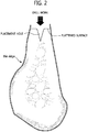
- FIG. 2 illustrates the thin ridge alveolar bone of FIG. 1 where a flattening work is performed.
- FIG. 3 illustrates a process of performing a flattening work by using a dental flattening drill according to an embodiment.
- the alveolar bone is first punched and a screw hole is formed in a punched hole.
- a screw hole (or fixture placement hole) is formed without a preliminary preparation work.
- the alveolar bone is not general and is irregular, for example, the end portion of the alveolar bone is excessively narrow and irregular as illustrated in FIGS. 1 and 12 , that is, the alveolar bone has a thin ridge, the above method may not be employed as it is.
- a placement hole is formed by drilling the alveolar bone at a position where the fixture is to be placed by a predetermined depth and a flat surface is formed on an end portion of the thin ridge by flattening the end portion of the thin ridge.
- the present embodiment discloses a dental flattening drill 100 having a structure as illustrated in FIGS. 3 to 12 so that the fixture placement position may be easily, accurately, and previously drilled on an irregular alveolar bone having a thin ridge and further an area of the end portion thereof is flattened.
- the dental flattening drill 100 according to the present embodiment may be arranged on the end portion of the thin ridge, as illustrated in FIG. 3 , and used to form a placement hole and a flattened surface at the end portion of the thin ridge.
- the placement hole and the flattened surface are formed at the end portion of the thin ridge by using a single tool, not separate equipment, efficiency of work is improved.
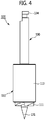
- FIG. 4 is an enlarged view of the dental flattening drill of FIG. 3 .
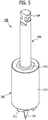
- FIGS. 5 and 6 are perspective views of the dental flattening drill viewed at different angles.
- FIGS. 7 and 8 are perspective views of a drill housing viewed at different angles.
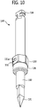
- FIGS. 9 and 10 are perspective views of a drill lance viewed at different angles.
- FIG. 11 is a vertical sectional view of FIG. 4 .
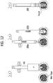
- FIG. 12 is an image showing steps of a process of placing a fixture after flattening a thin ridge by using a dental flattening drill, according to an embodiment.
- the dental flattening drill 100 may enable easy, accurate, and previous drilling at a position for placing a fixture with respect to an irregular alveolar bone like a thin ridge and flattening an area of an end portion of the alveolar bone, and may include two parts, that is, a drill lance 130 and a drill housing 110, which are disassembled from and assembled to each other.
- the drill lance 130 and the drill housing 110 is assembled to each other and used as illustrated in FIG. 3 and can be disassembled from each other for cleaning the inside or for maintenance or repair.
- the drill lance 130 and the drill housing 110 assembled to each other can be arranged at the end portion of the thin ridge, as illustrated in FIG. 3 , to perform a drill work by being rotated by a separate drill driving equipment (not shown).
- the drill lance 130 drills the alveolar bone at a placement position where the fixture is to be placed by a predetermined depth, thereby forming the placement hole.
- the drill lance 130 can be coupled to the drill housing 110 and rotated with the drill housing 110.
- the drill lance 130 can includes a unit shaft 132 and a boss 133 provided at one side of the unit shaft 132 and caught and supported by a boss catching step 115.
- the unit shaft 132 is a long rod type structure, and a drill blade 131, that is, an awl type drill blade 131 having a sharp tip end is provided at one end portion of the unit shaft 132.
- the awl type drill blade 131 having a sharp end portion is provided so that a placement hole is formed at a thin ridge by using the drill lance 130 as illustrated in FIGS. 2 and 3 .
- a placement hole having a shape as illustrated in FIGS. 2 and 3 can be formed in the thin ridge.
- the awl type drill blade 131 can be manufactured in a triangular pyramid shape.
- the awl type drill blade 131 provided on the drill lance 130 can be arranged radially inside an end mill processing blade 111 of the drill housing 110 that is described later.
- the awl type drill blade 131 of the drill lance 130 protrudes more than the end mill processing blade 111 of the drill housing 110 in a direction in which the drill lance 130 is coupled to the drill housing 110. Accordingly, the placement hole is formed aside from a flattened surface.
- a tool mounting portion 134 is provided at the other end portion of the unit shaft 132.
- the tool mounting portion 134 may be a place to be used for mounting the dental flattening drill 100 according to the present embodiment on the separate drill driving equipment.
- the boss 133 is caught and supported by the boss catching step 115 of the drill housing 110.
- the drill lance 130 may be inserted into the drill housing 110 until the boss 133 is caught and supported by the boss catching step 115.
- an outer wall of the boss 133 and an inner wall of a housing body 113 contacting each other may have a non-circular shape so that the drill lance 130 is not freely rotated in the drill housing 110.
- the boss 133 has a shape like a hexagonal nut, and an inner wall of the housing body 113 is manufactured to have six faces corresponding to the hexagonal nut. Accordingly, when the boss 133 is inserted into the inner wall of the housing body 113, the boss 133 may not be freely rotated.
- boss 133 does not necessarily have the shape like the hexagonal nut, the right scope of the present inventive concept may not be limited to the shape presented on the drawings.
- a cylindrical insertion portion 135 is provided on a side surface of the boss 133 toward the awl type drill blade 131.
- the cylindrical insertion portion 135 is inserted into an insertion hole 116 (see FIG. 8 ) of the drill housing 110 so that a coupling force between the drill lance 130 and the drill housing 110 is improved.
- the drill housing 110 is a cylindrical structure to which the drill lance 130 is detachably coupled, and flattens an upper portion of the alveolar bone around the placement hole at the thin ridge as illustrated in FIG. 2 , thereby forming a flattened surface.
- a processing blade that is, the end mill processing blade 111 having blades on a bottom and lateral surfaces thereof, is formed on an end portion of the drill housing 110 to flatten the upper portion of the alveolar bone around the placement hole.
- the end mill processing blade 111 can be arranged radially outside the awl type drill blade 131 provided on the drill lance 130, forming the flattened surface on the thin ridge at its position.
- the drill housing 110 has a hollow pipe shape so that the drill lance 130 may pass therethrough.
- the drill housing 110 may include the housing body 113 as a cylindrical structure.
- the end mill processing blade 111 for a flattening work of the thin ridge is formed on a leading end portion of the housing body 113 that is a hollow pipe structure.
- the end mill processing blade 111 also has a function of keeping a position of the awl type drill blade 131 provided on the drill lance 130 not to escape from the position when the awl type drill blade 131 is shaken during rotation.
- the end mill processing blade 111 rotates together with the awl type drill blade 131 and performs a flattening work on the upper portion of the thin ridge.
- the end mill processing blade 111 may be continuously formed in a circumferential direction on a leading end portion of the drill housing 110. Accordingly, shaking during the thin ridge flattening work decreases so that the flattening work may be stably performed.
- An alveolar bone crushed powder storing space portion 112 (see FIG. 11 ) for storing crushed powder of the alveolar bone produced when the alveolar bone is crushed is provided inside the housing body 113.
- the alveolar bone is crushed and crushed powder or some clods of the alveolar bone can be gathered inside the housing body 113, that is, a space between the drill lance 130 and the hosing body 113.
- the alveolar bone crushed powder gathered as above may be used during guide bone regeneration (GBR).
- GLR guide bone regeneration
- the alveolar bone crushed powder stored in the above space may be collected by separating the drill lance 130 and the drill housing 110.
- GBR refers to a surgery performed to promote bone formation using a shield film when no sufficient amount of alveolar bone exists around a placed fixture or the alveolar bone is insufficient at a place where the fixture is to be placed. In this state, it is known that, when a patient's own bone is used, the surgery may be more easily performed.
- a ball accommodation portion 152 that is a constituent element of a detachable coupling portion 150 is provided on an upper end portion of the inner wall of the housing body 113, which is described later.
- the boss catching step 115 is provided on the upper end portion of the inner wall of the housing body 113, forming a place where the boss 133 of the drill lance 130 is caught and supported.
- the drill lance 130 when the drill lance 130 is inserted into the drill housing 110 to couple or assemble the drill lance 130 to the drill housing 110, the drill lance 130 can be inserted into the drill housing 110 only to the boss catching step 115 where the boss 133 of the drill lance 130 is caught and supported. In this state, the drill lance 130 may be coupled or assembled to the drill housing 110.
- the dental flattening drill 100 further includes the detachable coupling portion 150 to allow the drill lance 130 to be detachably coupled to the drill housing 110.
- the detachable coupling portion 150 is provided between the drill lance 130 and the drill housing 110 and detachably coupling the drill lance 130 to the drill housing 110. Since the detachable coupling portion 150 is provided between the drill lance 130 and the drill housing 110 so that the drill lance 130 and the drill housing 110 are detachably coupled to each other, several drill housing (not shown) having different diameters can be commonly used with respect to one drill lance.
- the dental flattening drill according to the present embodiment is easily applied to patients having different thin ridge areas.
- a drill housing having a relatively small diameter is first used and then a drill housing having a relatively large diameter can be used, a flattening work can be easily performed.
- the detachable coupling portion 150 applied to the dental flattening drill 100 of the present embodiment is provided in the boss 133 of the drill lance 130 and the housing body 113 of the drill housing 110. However, the detachable coupling portion 150 is provided at a different position, regardless of positions.
- the detachable coupling portion 150 may include a ball plunger 151 provided on any one of the boss 133 of the drill lance 130 and the housing body 113 of the drill housing 110 and the ball accommodation portion 152 provided on the other one of the boss 133 of the drill lance 130 and the housing body 113 of the drill housing 110 and accommodating the ball plunger 151.
- the ball plunger 151 protrudes from an outer wall of the boss 133 of the drill lance 130, whereas the ball accommodation portion 152 is concavely formed in the inner wall of the housing body 113 of the drill housing 110.
- the ball plunger 151 may protrude from the inner wall of the housing body 113 of the drill housing 110, whereas the ball accommodation portion 152 can be concavely formed in the outer wall of the boss 133 of the drill lance 130.
- both the ball plunger 151 and the ball accommodation portion 152 is provided by one.
- the ball accommodation portion 152 can be provided by a plural number and arranged regularly along a circumferential direction of the inner wall of the housing body 113 of the drill housing 110.
- the ball plunger 151 includes a ball 151a that can be selectively inserted into the ball accommodation portion 152 and an elastic member 151b contacting the ball 151a and elastically pressing the ball 151a in a direction in which the ball 151a is inserted into the ball accommodation portion 152.
- a guide groove 153 for guiding the ball plunger 151 is formed in the inner wall of the drill housing 110 where the ball accommodation portion 152 is formed. Accordingly, when the drill lance 130 and the drill housing 110 are coupled to each other, the ball plunger 151 is guide along the guide groove 153 and then accommodated in the ball accommodation portion 152. Accordingly, a coupling work between the drill lance 130 and the drill housing 110 can be performed very smoothly.
- the drill lance 130 and the drill housing 110 are assembled to each other by using the detachable coupling portion 150 and arranged at an end portion of a thin ridge and rotated as illustrated in FIGS. 3 and FIG. 12 (1).
- a placement hole and a flattened surface are respectively formed by the awl type drill blade 131 of the drill lance 130 and the end mill processing blade 111 of the drill housing 110, in an upper end of the thin ridge.
- the drill housing 110 having a diameter ( ⁇ ) of 5 mm can be used.
- the drill housing 110 having a diameter ( ⁇ ) of 6 mm can be used.
- the hole where the fixture is to be placed is processed further deeper by sequentially using the final drills 200a and 200b as illustrated in FIG. 12 (2).
- the fixture is placed at its position and fixed thereto by using separate equipment (Handpiece & Ratchet Connector).
- the dental flattening drill since drilling is easily, accurately, and previously performed at a position for placing a fixture in an irregular alveolar bone like a thin ridge and an area of an end portion of the alveolar bone is flattened, the fixture can be stably fixed at an accurate position.
- the present invention can be used in dental treatment for implant surgery.
Landscapes
- Health & Medical Sciences (AREA)
- Oral & Maxillofacial Surgery (AREA)
- Dentistry (AREA)
- Epidemiology (AREA)
- Life Sciences & Earth Sciences (AREA)
- Animal Behavior & Ethology (AREA)
- General Health & Medical Sciences (AREA)
- Public Health (AREA)
- Veterinary Medicine (AREA)
- Orthopedic Medicine & Surgery (AREA)
- Engineering & Computer Science (AREA)
- Mechanical Engineering (AREA)
- Dental Prosthetics (AREA)
- Dental Tools And Instruments Or Auxiliary Dental Instruments (AREA)
Description
- The inventive concept relates to a dental flattening drill, and more particularly, to a dental flattening drill which may enable easy, accurate, and previous drilling at a position for placing a fixture with respect to an irregular alveolar bone like a thin ridge and flattening an area of an end portion of the alveolar bone so that the fixture can be stably fixed at an accurate position.
- An implant originally means a substitute used to restore lost human tissues. In a dental field, however, the implant refers to a series of procedures to transplant an artificial tooth.
- In other words, to replace a lost dental root, the implant is a series of dental procedures to restore a function of a tooth by placing a fixture, which is a dental root formed of titanium and having no rejection to a human body, in an alveolar bone where a tooth is lost, and then fixing an artificial tooth thereto.
- In the case of a general prosthesis or denture, surrounding teeth or bones may be damaged as time passes. In contrast, since the implant does not harm the surrounding tooth tissues, provides the same function and shape as a natural tooth, has no tooth decay, the implant may be used semi-permanently.
- In an artificial tooth surgery (referred to as an implant surgery), a screw hole is formed by using a drill in an alveolar bone at a position where a fixture is to be placed, the fixture is placed in the screw hole to have osseointegration with the bone forming an artificial dental root, and an abutment is coupled to the fixture and crowned with an artificial tooth that is a final prosthesis.
- The implant as above may facilitate restoration of a single missing tooth, enhance the function of a denture for partially toothless and fully toothless patients, improve an aesthetic aspect of dental prosthesis restoration, and furthermore distribute excessive stress applied to surrounding support bone tissues and stabilize a row of teeth.
- As described above, in order to place the fixture, a screw hole is formed by punching a hole in the alveolar bone by using a drill.
- The drill work is briefly discussed below. The drill work described below is a mere example and there may be a variety of types of drill works.
- First, a position where a fixture is to be placed is determined on a surface of the alveolar bon by using a round drill as an initial drill,
- Next, after cutting and slightly opening an end portion of the alveolar bone where a tooth is lost, a hole of a predetermined depth is punched by mounting a guide drill on a predetermined tool, with water supplied to the alveolar bone.
- The hole is enlarged by using a first drill with water supplied to the alveolar bone, and an end portion of the hole is enlarged by using a pilot drill with water supplied to the alveolar bone.
- Next, a lower end portion of the hole is enlarged by using a final drill with water supplied to the alveolar bone.
- The screw hole for placing a fixture is completed by forming a screw thread in the hole by using a tap drill with water supplied to the alveolar bone.
- The above drill work, that is, the forming of a screw hole in the alveolar bone by punching, may be generally applied to patients having a general mouth structure, in particular, having a normal ridge, that is, an end portion of the alveolar bone is large.
- However, when the alveolar bone is not general, that is, irregular, for example, the end portion of the alveolar bone is excessively narrow, that is, the alveolar bone forms a thin ridge, the above method may not be employed as it is.
- In other words, since the thin ridge has an excessively narrow end portion, the drill work is unavoidably performed on an inclined surface. When the drill work is performed on the inclined surface, the drill work may not be smoothly performed because the drill slips on the inclined surface. Accordingly, it is difficult to form the screw hole in the alveolar bone.
- Thus, when the alveolar bone has the thin ridge that is not general and is irregular, a flattening work to make a surface where the fixture is to be placed flat is performed ahead to make a flat surface and the above-described drill work is performed on a flattened surface, thereby forming the screw hole.
- As such, the surgery may be made easy and accurate by using a drill suitable for the flattening work to flatten the end portion of the thin ridge.
- In other words, there is a demand for development of technologies regarding new dental flattening drills which may enable easy, accurate, and previous drilling at a position for placing a fixture with respect to an irregular alveolar bone like the thin ridge and also flatten an area of the end portion of the alveolar bone.
-
US 2005/003327 A1 discloses a method for drilling a hole for placement of an implant therein which an initial hole is formed in the jaw bone having a diameter smaller than a desired diameter for placement of the implant and a depth smaller than a desired depth for placement of the implant. -
US 1 333 388 A -
KR 2004 67202 Y1 - The inventive concept provides a dental flattening drill which may enable easy, accurate, and previous drilling at a position for placing a fixture with respect to an irregular alveolar bone like a thin ridge and flattening an area of an end portion of the alveolar bone so that the fixture can be stably fixed at an accurate position.
- According to the present inventive concept, since drilling is easily, accurately, and previously performed at a position for placing a fixture in an irregular alveolar bone like a thin ridge and an area of an end portion of the alveolar bone is flattened, the fixture can be stably fixed at an accurate position.
-
-
FIG. 1 illustrates a thin ridge alveolar bone; -
FIG. 2 illustrates the thin ridge alveolar bone ofFIG. 1 where a flattening work is performed; -
FIG. 3 illustrates a process of performing a flattening work by using a dental flattening drill according to the invention; -
FIG. 4 is an enlarged view of the dental flattening drill ofFIG. 3 ; -
FIGS. 5 and6 are perspective views of the dental flattening drill viewed at different angles; -
FIGS. 7 and8 are perspective views of a drill housing viewed at different angles; -
FIGS. 9 and10 are perspective views of a drill lance viewed at different angles; -
FIG. 11 is a vertical sectional view ofFIG. 4 ; and -
FIG. 12 is an image showing steps of a process of placing a fixture after flattening a thin ridge by using a dental flattening drill according to the invention; wherein the process itself does not form part of the invention. - According to the inventive concept, there is provided a dental flattening drill as defined by
claim 1. Further advantageous embodiments of the present invention are defined by the dependent claims. The dental flattening drill includes a drill lance having a drill blade that forms a placement hole by drilling an alveolar bone at a placement position where a fixture is to be placed by a preset depth, and a drill housing, to which the drill lance is detachably coupled, having a processing blade that flattens an area of the alveolar bone around the placement hole.The drill blade is arranged radially inside an end mill processing blade of the drill housing. - The drill blade of the drill lance protrudes more than the processing blade of the drill housing in a direction in which the drill lance is coupled to the drill housing.
- The drill lance includes a unit shaft having one end portion where the drill blade is formed, and a boss provided on one side of the unit shaft and caught and supported by the drill housing.
- The drill blade is an awl type drill blade having a sharp end portion, the awl type drill blade has a triangular pyramid shape, and the boss may have a polygonal sectional shape.
- The drill lance further includes a cylindrical insertion portion provided on a side surface of the boss toward the drill blade, and a tool mounting portion provided on the other end portion of the unit shaft.
- The processing blade is continuously formed along a circumferential direction of a leading end portion of the drill housing.
- The drill housing has a shape of a hollow pipe through which the drill lance passes. An alveolar bone crushed powder storing space portion storing alveolar bone crushed powder produced when the alveolar bone is crushed may be provided inside the drill housing.
- The processing blade is an end mill processing blade having blades on a bottom and lateral surfaces. The drill housing includes a housing body having an end portion where the end mill processing blade is formed, a boss catching step, by
which the boss of the drill lance is caught and supported, is provided in the housing body, and an insertion hole, into which a cylindrical insertion portion of the drill lance is inserted, is formed inside the boss catching step. - An outer wall of the boss and an inner wall of the housing body contacting each other has a non-circular shape.
- The dental flattening drill further includes a detachable coupling portion provided on the drill lance and the drill housing and detachably coupling the drill lance to the drill housing.
- The detachable coupling portion includes a ball plunger provided in any one of the drill lance and the drill housing and including a ball and an elastic member elastically pressing the ball, and a ball accommodation portion provided in the other one of the drill lance and the drill housing and accommodating the ball plunger.
- The ball plunger protrudes from an outer wall of one side of the drill lance, and the ball accommodation portion is concavely formed in an inner wall of the drill housing and provided by a plural number to be regularly arranged in a circumferential direction of the inner wall of the drill housing.
- A guide groove guiding the ball of the ball plunger is further formed in an inner wall of the drill housing where the ball accommodation portion is formed.
- The alveolar bone is a thin ridge having an end portion that is relatively narrow and irregular.
- The attached drawings for illustrating exemplary embodiments of the inventive concept are referred to in order to gain a sufficient understanding of the inventive concept and the merits thereof.
- Hereinafter, the inventive concept will be described in detail by explaining exemplary embodiments of the inventive concept with reference to the attached drawings. Like reference numerals in the drawings denote like elements.
-
FIG. 1 illustrates a thin ridge alveolar bone.FIG. 2 illustrates the thin ridge alveolar bone ofFIG. 1 where a flattening work is performed.FIG. 3 illustrates a process of performing a flattening work by using a dental flattening drill according to an embodiment. - As described above, in order to place a fixture (see
FIG. 12 ) in an alveolar bone for an implant surgery, the alveolar bone is first punched and a screw hole is formed in a punched hole. - In the case of a general patient having an alveolar bone with a wide end portion (normal ridge), a screw hole (or fixture placement hole) is formed without a preliminary preparation work.
- However, when the alveolar bone is not general and is irregular, for example, the end portion of the alveolar bone is excessively narrow and irregular as illustrated in
FIGS. 1 and12 , that is, the alveolar bone has a thin ridge, the above method may not be employed as it is. - In this case, as illustrated in
FIG. 2 , a placement hole is formed by drilling the alveolar bone at a position where the fixture is to be placed by a predetermined depth and a flat surface is formed on an end portion of the thin ridge by flattening the end portion of the thin ridge. By doing so, accurate placement of the fixture as illustrated inFIG. 12 may be possible. - Accordingly, the present embodiment discloses a
dental flattening drill 100 having a structure as illustrated inFIGS. 3 to 12 so that the fixture placement position may be easily, accurately, and previously drilled on an irregular alveolar bone having a thin ridge and further an area of the end portion thereof is flattened. - The
dental flattening drill 100 according to the present embodiment may be arranged on the end portion of the thin ridge, as illustrated inFIG. 3 , and used to form a placement hole and a flattened surface at the end portion of the thin ridge. In particular, in the case of thedental flattening drill 100 according to the present embodiment, since the placement hole and the flattened surface are formed at the end portion of the thin ridge by using a single tool, not separate equipment, efficiency of work is improved. -
FIG. 4 is an enlarged view of the dental flattening drill ofFIG. 3 .FIGS. 5 and6 are perspective views of the dental flattening drill viewed at different angles.FIGS. 7 and8 are perspective views of a drill housing viewed at different angles.FIGS. 9 and10 are perspective views of a drill lance viewed at different angles.FIG. 11 is a vertical sectional view ofFIG. 4 .FIG. 12 is an image showing steps of a process of placing a fixture after flattening a thin ridge by using a dental flattening drill, according to an embodiment. - Referring to
FIGS. 4 to 12 , thedental flattening drill 100 according to the present embodiment may enable easy, accurate, and previous drilling at a position for placing a fixture with respect to an irregular alveolar bone like a thin ridge and flattening an area of an end portion of the alveolar bone, and may include two parts, that is, adrill lance 130 and adrill housing 110, which are disassembled from and assembled to each other. - The
drill lance 130 and thedrill housing 110 is assembled to each other and used as illustrated inFIG. 3 and can be disassembled from each other for cleaning the inside or for maintenance or repair. In other words, thedrill lance 130 and thedrill housing 110 assembled to each other can be arranged at the end portion of the thin ridge, as illustrated inFIG. 3 , to perform a drill work by being rotated by a separate drill driving equipment (not shown). - First, the
drill lance 130 drills the alveolar bone at a placement position where the fixture is to be placed by a predetermined depth, thereby forming the placement hole. - The
drill lance 130 can be coupled to thedrill housing 110 and rotated with thedrill housing 110. - The
drill lance 130 can includes aunit shaft 132 and aboss 133 provided at one side of theunit shaft 132 and caught and supported by aboss catching step 115. - The
unit shaft 132 is a long rod type structure, and adrill blade 131, that is, an awltype drill blade 131 having a sharp tip end is provided at one end portion of theunit shaft 132. In other words, the awltype drill blade 131 having a sharp end portion is provided so that a placement hole is formed at a thin ridge by using thedrill lance 130 as illustrated inFIGS. 2 and3 . - As the awl
type drill blade 131 is rotated by being arranged at the thin ridge, a placement hole having a shape as illustrated inFIGS. 2 and3 can be formed in the thin ridge. - In the present embodiment, the awl
type drill blade 131 can be manufactured in a triangular pyramid shape. The awltype drill blade 131 provided on thedrill lance 130 can be arranged radially inside an endmill processing blade 111 of thedrill housing 110 that is described later. - In addition, the awl
type drill blade 131 of thedrill lance 130 protrudes more than the endmill processing blade 111 of thedrill housing 110 in a direction in which thedrill lance 130 is coupled to thedrill housing 110. Accordingly, the placement hole is formed aside from a flattened surface. - A
tool mounting portion 134 is provided at the other end portion of theunit shaft 132. Thetool mounting portion 134 may be a place to be used for mounting thedental flattening drill 100 according to the present embodiment on the separate drill driving equipment. - The
boss 133 is caught and supported by theboss catching step 115 of thedrill housing 110. Thedrill lance 130 may be inserted into thedrill housing 110 until theboss 133 is caught and supported by theboss catching step 115. - In this state, an outer wall of the
boss 133 and an inner wall of ahousing body 113 contacting each other may have a non-circular shape so that thedrill lance 130 is not freely rotated in thedrill housing 110. - In the present invention, the
boss 133 has a shape like a hexagonal nut, and an inner wall of thehousing body 113 is manufactured to have six faces corresponding to the hexagonal nut. Accordingly, when theboss 133 is inserted into the inner wall of thehousing body 113, theboss 133 may not be freely rotated. - Also, since the
boss 133 does not necessarily have the shape like the hexagonal nut, the right scope of the present inventive concept may not be limited to the shape presented on the drawings. - A
cylindrical insertion portion 135 is provided on a side surface of theboss 133 toward the awltype drill blade 131. When thedrill lance 130 is coupled to thedrill housing 110, thecylindrical insertion portion 135 is inserted into an insertion hole 116 (seeFIG. 8 ) of thedrill housing 110 so that a coupling force between thedrill lance 130 and thedrill housing 110 is improved. - Next, the
drill housing 110 is a cylindrical structure to which thedrill lance 130 is detachably coupled, and flattens an upper portion of the alveolar bone around the placement hole at the thin ridge as illustrated inFIG. 2 , thereby forming a flattened surface. - A processing blade, that is, the end
mill processing blade 111 having blades on a bottom and lateral surfaces thereof, is formed on an end portion of thedrill housing 110 to flatten the upper portion of the alveolar bone around the placement hole. - As described above, the end
mill processing blade 111 can be arranged radially outside the awltype drill blade 131 provided on thedrill lance 130, forming the flattened surface on the thin ridge at its position. - As illustrated in
FIG. 11 , since thedrill lance 130 is coupled (assembled) to thedrill housing 110 by being partially inserted into thedrill housing 110, thedrill housing 110 has a hollow pipe shape so that thedrill lance 130 may pass therethrough. - The
drill housing 110 may include thehousing body 113 as a cylindrical structure. The endmill processing blade 111 for a flattening work of the thin ridge is formed on a leading end portion of thehousing body 113 that is a hollow pipe structure. - In particular, the end
mill processing blade 111 also has a function of keeping a position of the awltype drill blade 131 provided on thedrill lance 130 not to escape from the position when the awltype drill blade 131 is shaken during rotation. The endmill processing blade 111 rotates together with the awltype drill blade 131 and performs a flattening work on the upper portion of the thin ridge. - The end
mill processing blade 111 may be continuously formed in a circumferential direction on a leading end portion of thedrill housing 110. Accordingly, shaking during the thin ridge flattening work decreases so that the flattening work may be stably performed. - An alveolar bone crushed powder storing space portion 112 (see
FIG. 11 ) for storing crushed powder of the alveolar bone produced when the alveolar bone is crushed is provided inside thehousing body 113. - In other words, when the flattening work is performed on the alveolar bone as illustrated in
FIG. 3 , the alveolar bone is crushed and crushed powder or some clods of the alveolar bone can be gathered inside thehousing body 113, that is, a space between thedrill lance 130 and the hosingbody 113. The alveolar bone crushed powder gathered as above may be used during guide bone regeneration (GBR). In this state, the alveolar bone crushed powder stored in the above space may be collected by separating thedrill lance 130 and thedrill housing 110. - For reference, GBR refers to a surgery performed to promote bone formation using a shield film when no sufficient amount of alveolar bone exists around a placed fixture or the alveolar bone is insufficient at a place where the fixture is to be placed. In this state, it is known that, when a patient's own bone is used, the surgery may be more easily performed.
- A
ball accommodation portion 152 that is a constituent element of adetachable coupling portion 150 is provided on an upper end portion of the inner wall of thehousing body 113, which is described later. - The
boss catching step 115 is provided on the upper end portion of the inner wall of thehousing body 113, forming a place where theboss 133 of thedrill lance 130 is caught and supported. In other words, when thedrill lance 130 is inserted into thedrill housing 110 to couple or assemble thedrill lance 130 to thedrill housing 110, thedrill lance 130 can be inserted into thedrill housing 110 only to theboss catching step 115 where theboss 133 of thedrill lance 130 is caught and supported. In this state, thedrill lance 130 may be coupled or assembled to thedrill housing 110. - The
dental flattening drill 100 according to the present embodiment further includes thedetachable coupling portion 150 to allow thedrill lance 130 to be detachably coupled to thedrill housing 110. - In other words, the
detachable coupling portion 150 is provided between thedrill lance 130 and thedrill housing 110 and detachably coupling thedrill lance 130 to thedrill housing 110. Since thedetachable coupling portion 150 is provided between thedrill lance 130 and thedrill housing 110 so that thedrill lance 130 and thedrill housing 110 are detachably coupled to each other, several drill housing (not shown) having different diameters can be commonly used with respect to one drill lance. - Accordingly, the dental flattening drill according to the present embodiment is easily applied to patients having different thin ridge areas. In addition, since a drill housing having a relatively small diameter is first used and then a drill housing having a relatively large diameter can be used, a flattening work can be easily performed.
- The
detachable coupling portion 150 applied to thedental flattening drill 100 of the present embodiment is provided in theboss 133 of thedrill lance 130 and thehousing body 113 of thedrill housing 110. However, thedetachable coupling portion 150 is provided at a different position, regardless of positions. - The
detachable coupling portion 150 may include aball plunger 151 provided on any one of theboss 133 of thedrill lance 130 and thehousing body 113 of thedrill housing 110 and theball accommodation portion 152 provided on the other one of theboss 133 of thedrill lance 130 and thehousing body 113 of thedrill housing 110 and accommodating theball plunger 151. - In the present embodiment, the
ball plunger 151 protrudes from an outer wall of theboss 133 of thedrill lance 130, whereas theball accommodation portion 152 is concavely formed in the inner wall of thehousing body 113 of thedrill housing 110. - However, the opposite case is available. In other words, the
ball plunger 151 may protrude from the inner wall of thehousing body 113 of thedrill housing 110, whereas theball accommodation portion 152 can be concavely formed in the outer wall of theboss 133 of thedrill lance 130. - In this case, it is sufficient that both the
ball plunger 151 and theball accommodation portion 152 is provided by one. However, in the present embodiment, theball accommodation portion 152 can be provided by a plural number and arranged regularly along a circumferential direction of the inner wall of thehousing body 113 of thedrill housing 110. - When the
ball accommodation portion 152 is provided by a plural number as in the present embodiment, a coupling or assembling work between thedrill lance 130 and thedrill housing 110 may be made easy. - The
ball plunger 151 includes aball 151a that can be selectively inserted into theball accommodation portion 152 and anelastic member 151b contacting theball 151a and elastically pressing theball 151a in a direction in which theball 151a is inserted into theball accommodation portion 152. - A
guide groove 153 for guiding theball plunger 151 is formed in the inner wall of thedrill housing 110 where theball accommodation portion 152 is formed. Accordingly, when thedrill lance 130 and thedrill housing 110 are coupled to each other, theball plunger 151 is guide along theguide groove 153 and then accommodated in theball accommodation portion 152. Accordingly, a coupling work between thedrill lance 130 and thedrill housing 110 can be performed very smoothly. - A series of processes to place the fixture by using the
dental flattening drill 100 according to the present embodiment is described below with reference toFIGS. 3 and12 . - First, the
drill lance 130 and thedrill housing 110 are assembled to each other by using thedetachable coupling portion 150 and arranged at an end portion of a thin ridge and rotated as illustrated inFIGS. 3 andFIG. 12 (1). - Then, a placement hole and a flattened surface are respectively formed by the awl
type drill blade 131 of thedrill lance 130 and the endmill processing blade 111 of thedrill housing 110, in an upper end of the thin ridge. In this state, as illustrated inFIG. 12 (2), whenfinal drills drill housing 110 having a diameter (Ø) of 5 mm can be used. As illustrated inFIG. 12 (2), when thefinal drills drill housing 110 having a diameter (Ø) of 6 mm can be used. The above figures are merely for reference and the present disclosure is not limited thereto. - When the placement hole and the flattened surface are formed on the upper end of the thin ridge by using the
dental flattening drill 100 according to the present embodiment, the hole where the fixture is to be placed is processed further deeper by sequentially using thefinal drills FIG. 12 (2). - Then, as illustrated in
FIG. 12 (3), the fixture is placed at its position and fixed thereto by using separate equipment (Handpiece & Ratchet Connector). - As described above, according to the dental flattening drill according to the present inventive concept configured as above, since drilling is easily, accurately, and previously performed at a position for placing a fixture in an irregular alveolar bone like a thin ridge and an area of an end portion of the alveolar bone is flattened, the fixture can be stably fixed at an accurate position.
- While the inventive concept has been particularly shown and described with reference to exemplary embodiments thereof, it will be understood that various changes in form and details can be made therein without departing from the scope of the following claims.
- The present invention can be used in dental treatment for implant surgery.
Claims (5)
- A dental flattening drill (100) comprising:a drill lance (130) and a drill housing (110),the drill lance (130) comprising:a drill blade (131) configured to form a placement hole by drilling an alveolar bone at a placement position where a fixture is to be placed by a preset depth;a unit shaft (132) having one end portion where the drill blade is formed;a boss (133) provided on one side of the unit shaft and caught and supported by the drill housing (110);a detachable coupling portion (150) provided on the drill lance (130) and the drill housing (110) and detachably coupling the drill lance to the drill housing;a cylindrical insertion portion (135) provided on a side surface of the boss (133) toward the drill blade (131); anda tool mounting portion (134) provided on the other end portion of the unit shaft (132);the drill housing (110), to which the drill lance is detachably coupled, comprising:a processing blade (111) configured to flatten an area of the alveolar bone around the placement hole wherein the processing blade is an end mill processing blade having blades on a bottom and lateral surfaces; wherein the processing blade (111) is continuously formed along a circumferential direction of a leading end portion of the drill housing (110);a housing body (113) having an end portion where the end mill processing blade is formed,a boss catching step (115), by which the boss of the drill lance is caught and supported, is provided in the housing body, andan insertion hole (116), into which a cylindrical insertion portion of the drill lance is inserted, is formed inside the boss catching step,wherein the drill blade (131) of the drill lance is an awl type drill blade having a sharp end portion, wherein the awl type drill blade has a triangular pyramid shape, and the boss (133) has a polygonal sectional shape, is arranged radially inside an end mill processing blade of the drill housing, and protrudes more than the processing blade (111) of the drill housing in a direction in which the drill lance (130) is coupled to the drill housing;wherein an outer wall of the boss and an inner wall of the housing body contacting each other have a non-circular shape.wherein the detachable coupling portion comprises: a ball plunger (151) provided in any one of the drill lance and the drill housing and comprising a ball (151a) and an elastic member (151b) elastically pressing the ball; and a ball accommodation portion (152) provided in the other one of the drill lance and the drill housing and accommodating the ball plunger.
- The dental flattening drill of claim 1, wherein the drill housing (110) has a shape of a hollow pipe through which the drill lance (130) passes.
- The dental flattening drill of claim 1, wherein an alveolar bone crushed powder storing space portion (112) storing alveolar bone crushed powder produced when the alveolar bone is crushed is provided inside the drill housing (110).
- The dental flattening drill of claim 1, wherein the ball plunger (150) protrudes from an outer wall of one side of the drill lance (130), and the ball accommodation portion (152) is concavely formed in an inner wall of the drill housing (110) and provided by a plural number to be regularly arranged in a circumferential direction of the inner wall of the drill housing.
- The dental flattening drill of claim 1, wherein a guide groove (153) guiding the ball of the ball plunger (151) is further formed in an inner wall of the drill housing where the ball accommodation portion (152) is formed.
Applications Claiming Priority (2)
| Application Number | Priority Date | Filing Date | Title |
|---|---|---|---|
| KR1020160011097A KR101720605B1 (en) | 2016-01-29 | 2016-01-29 | Dental Flattening Drill |
| PCT/KR2016/014000 WO2017131336A1 (en) | 2016-01-29 | 2016-11-30 | Dental flattening drill |
Publications (3)
| Publication Number | Publication Date |
|---|---|
| EP3409236A1 EP3409236A1 (en) | 2018-12-05 |
| EP3409236A4 EP3409236A4 (en) | 2019-02-27 |
| EP3409236B1 true EP3409236B1 (en) | 2021-04-07 |
Family
ID=58495582
Family Applications (1)
| Application Number | Title | Priority Date | Filing Date |
|---|---|---|---|
| EP16888312.2A Active EP3409236B1 (en) | 2016-01-29 | 2016-11-30 | Dental flattening drill |
Country Status (6)
| Country | Link |
|---|---|
| US (1) | US11399921B2 (en) |
| EP (1) | EP3409236B1 (en) |
| KR (1) | KR101720605B1 (en) |
| CN (1) | CN108712889B (en) |
| TW (1) | TWI621424B (en) |
| WO (1) | WO2017131336A1 (en) |
Families Citing this family (4)
| Publication number | Priority date | Publication date | Assignee | Title |
|---|---|---|---|---|
| US11241293B2 (en) | 2018-03-04 | 2022-02-08 | Synthes Gmbh | Surgical instrument handle with implant sizing feature and method of using |
| US11147542B2 (en) | 2018-03-04 | 2021-10-19 | Synthes Gmbh | Surgical instrument handle with implant sizing feature and method of using |
| AU2020206880A1 (en) * | 2019-01-10 | 2021-07-22 | Synthes Gmbh | Surgical instrument handle with implant sizing feature |
| CN109875696A (en) * | 2019-03-07 | 2019-06-14 | 魏成石 | A kind of inverted cone bur for teeth restoration |
Citations (1)
| Publication number | Priority date | Publication date | Assignee | Title |
|---|---|---|---|---|
| KR200467202Y1 (en) * | 2011-08-05 | 2013-06-04 | (주) 코웰메디 | Initial Drill for operating implant with crestal cutter and pilot cutter |
Family Cites Families (23)
| Publication number | Priority date | Publication date | Assignee | Title |
|---|---|---|---|---|
| US1333388A (en) * | 1917-06-27 | 1920-03-09 | William E Chester | Dental drilling-tool |
| CN2097620U (en) * | 1991-07-11 | 1992-03-04 | 四川大学 | Surgical drill for artificial embedding tooth |
| US5613852A (en) * | 1995-01-06 | 1997-03-25 | Board Of Regents Univ Of Ne At Lincoln | Dental implant drill guide system |
| JP2001170078A (en) | 1999-12-16 | 2001-06-26 | Teiichi Hirashima | Dental implant, its implanting method, and drill used for the same |
| US6951462B2 (en) * | 2002-06-04 | 2005-10-04 | Zimmer Dental Inc. | Dental tool with rententive feature |
| JP4420423B2 (en) * | 2002-09-26 | 2010-02-24 | 株式会社ジーシー | Self-tapping dental screw type implant fixture drill set |
| US20050003327A1 (en) | 2003-05-12 | 2005-01-06 | Nicolas Elian | Drilling system and method for dental implants |
| TWM313500U (en) * | 2006-11-01 | 2007-06-11 | Chun-Leon Chen | Rapid dental implant drill |
| KR100759261B1 (en) * | 2007-01-15 | 2007-09-17 | 주식회사 메가젠 | Drill for operating implant |
| JP5165457B2 (en) * | 2008-05-21 | 2013-03-21 | 株式会社ジーシー | Removable stopper for dental drill |
| KR101166161B1 (en) * | 2010-04-12 | 2012-07-18 | 이태경 | Drill for the milling of surgical template |
| KR20120064143A (en) * | 2010-12-09 | 2012-06-19 | 이요섭 | Dental stopper device for drilling |
| TW201235013A (en) * | 2011-02-16 | 2012-09-01 | Metal Ind Res & Dev Ct | Implant dental drill kit, its drills and drill base |
| KR101192219B1 (en) * | 2011-02-23 | 2012-10-17 | 조선대학교산학협력단 | Drill for Operating Implant |
| KR101242868B1 (en) * | 2011-06-24 | 2013-03-12 | 엘에스산전 주식회사 | Rfid apparatus including movable rfid reader and antenna |
| KR20110095846A (en) | 2011-07-29 | 2011-08-25 | 김재육 | Air inject refill pack |
| US20140030674A1 (en) * | 2012-01-27 | 2014-01-30 | Hao Nguyen | Prefabricated immediate no-drill dental implant |
| CN202554148U (en) * | 2012-03-13 | 2012-11-28 | 陈俊龙 | Fast dental implant kit |
| KR101466311B1 (en) * | 2012-05-07 | 2014-12-02 | 주식회사 제노스 | Bone obtaining drill for implant |
| US9649177B2 (en) * | 2012-09-17 | 2017-05-16 | Martin DEBOLD | Dental implant set |
| CN203564352U (en) | 2013-10-25 | 2014-04-30 | 张英怀 | Planar positioning drill for tooth implantation |
| CN103519912B (en) * | 2013-10-25 | 2016-08-10 | 张英怀 | Plane location drill for dental implantation |
| CN204192766U (en) * | 2014-09-04 | 2015-03-11 | 宁波信远齿科器械有限公司 | Plant dental drill head fast |
-
2016
- 2016-01-29 KR KR1020160011097A patent/KR101720605B1/en active IP Right Grant
- 2016-11-30 EP EP16888312.2A patent/EP3409236B1/en active Active
- 2016-11-30 CN CN201680083386.4A patent/CN108712889B/en active Active
- 2016-11-30 WO PCT/KR2016/014000 patent/WO2017131336A1/en active Application Filing
- 2016-11-30 US US16/083,481 patent/US11399921B2/en active Active
- 2016-12-02 TW TW105139877A patent/TWI621424B/en active
Patent Citations (1)
| Publication number | Priority date | Publication date | Assignee | Title |
|---|---|---|---|---|
| KR200467202Y1 (en) * | 2011-08-05 | 2013-06-04 | (주) 코웰메디 | Initial Drill for operating implant with crestal cutter and pilot cutter |
Also Published As
| Publication number | Publication date |
|---|---|
| EP3409236A1 (en) | 2018-12-05 |
| WO2017131336A1 (en) | 2017-08-03 |
| US11399921B2 (en) | 2022-08-02 |
| CN108712889A (en) | 2018-10-26 |
| CN108712889B (en) | 2021-02-09 |
| KR101720605B1 (en) | 2017-03-28 |
| TWI621424B (en) | 2018-04-21 |
| TW201726075A (en) | 2017-08-01 |
| US20190209273A1 (en) | 2019-07-11 |
| EP3409236A4 (en) | 2019-02-27 |
Similar Documents
| Publication | Publication Date | Title |
|---|---|---|
| EP3409236B1 (en) | Dental flattening drill | |
| KR101192662B1 (en) | Drill for an implant operation | |
| EP2237739B1 (en) | Drill for sinus membrane lift | |
| JP5501361B2 (en) | Drill drill for implants | |
| KR100906692B1 (en) | Safety drill assembly for perfoming a surgical operation for periosteum in maxillary | |
| KR101758803B1 (en) | apparatus for implant drill | |
| TWI566750B (en) | Implant operation guide apparatus set and method of implantation using the same | |
| KR101067485B1 (en) | Stopper unit for implant drill and drill for operating implant having the same | |
| KR20070057392A (en) | Dental implant | |
| KR101516950B1 (en) | apparatus for abutment profile drill | |
| KR101516949B1 (en) | apparatus for bone flattening drill | |
| KR101977127B1 (en) | Trimming drill for alveolar bone and a drill kit for implant treatment having the same | |
| KR102027336B1 (en) | apparatus for bone flattening drill | |
| KR20090051839A (en) | Drill tool for block bone grafting | |
| KR101234296B1 (en) | Drill for operating implant | |
| JP2010063854A (en) | Dental implant | |
| JP6187862B2 (en) | Dental implant drilling system | |
| KR200475899Y1 (en) | Dental drill with stopper | |
| KR20120014373A (en) | Windows opener for lateral sinus graft surgical operation | |
| KR101181923B1 (en) | Drill for lateral sinus graft surgical operation | |
| KR101723967B1 (en) | Dental drill | |
| KR200487737Y1 (en) | A flattening drill for teeth | |
| JP7372888B2 (en) | Maxillary sinus floor fisting device | |
| KR101295821B1 (en) | Device for limiting drilling depth of a drill for dental surgery | |
| KR20100086561A (en) | Fixture of dental implant |
Legal Events
| Date | Code | Title | Description |
|---|---|---|---|
| STAA | Information on the status of an ep patent application or granted ep patent |
Free format text: STATUS: THE INTERNATIONAL PUBLICATION HAS BEEN MADE |
|
| PUAI | Public reference made under article 153(3) epc to a published international application that has entered the european phase |
Free format text: ORIGINAL CODE: 0009012 |
|
| STAA | Information on the status of an ep patent application or granted ep patent |
Free format text: STATUS: REQUEST FOR EXAMINATION WAS MADE |
|
| 17P | Request for examination filed |
Effective date: 20180829 |
|
| AK | Designated contracting states |
Kind code of ref document: A1 Designated state(s): AL AT BE BG CH CY CZ DE DK EE ES FI FR GB GR HR HU IE IS IT LI LT LU LV MC MK MT NL NO PL PT RO RS SE SI SK SM TR |
|
| AX | Request for extension of the european patent |
Extension state: BA ME |
|
| STAA | Information on the status of an ep patent application or granted ep patent |
Free format text: STATUS: EXAMINATION IS IN PROGRESS |
|
| A4 | Supplementary search report drawn up and despatched |
Effective date: 20190124 |
|
| RIC1 | Information provided on ipc code assigned before grant |
Ipc: A61C 1/08 20060101ALI20190118BHEP Ipc: A61C 8/00 20060101AFI20190118BHEP Ipc: B23B 51/08 20060101ALI20190118BHEP Ipc: A61C 3/02 20060101ALI20190118BHEP |
|
| 17Q | First examination report despatched |
Effective date: 20190211 |
|
| DAV | Request for validation of the european patent (deleted) | ||
| DAX | Request for extension of the european patent (deleted) | ||
| GRAP | Despatch of communication of intention to grant a patent |
Free format text: ORIGINAL CODE: EPIDOSNIGR1 |
|
| STAA | Information on the status of an ep patent application or granted ep patent |
Free format text: STATUS: GRANT OF PATENT IS INTENDED |
|
| INTG | Intention to grant announced |
Effective date: 20201119 |
|
| GRAS | Grant fee paid |
Free format text: ORIGINAL CODE: EPIDOSNIGR3 |
|
| GRAA | (expected) grant |
Free format text: ORIGINAL CODE: 0009210 |
|
| STAA | Information on the status of an ep patent application or granted ep patent |
Free format text: STATUS: THE PATENT HAS BEEN GRANTED |
|
| AK | Designated contracting states |
Kind code of ref document: B1 Designated state(s): AL AT BE BG CH CY CZ DE DK EE ES FI FR GB GR HR HU IE IS IT LI LT LU LV MC MK MT NL NO PL PT RO RS SE SI SK SM TR |
|
| REG | Reference to a national code |
Ref country code: GB Ref legal event code: FG4D |
|
| REG | Reference to a national code |
Ref country code: AT Ref legal event code: REF Ref document number: 1378675 Country of ref document: AT Kind code of ref document: T Effective date: 20210415 Ref country code: CH Ref legal event code: EP |
|
| REG | Reference to a national code |
Ref country code: DE Ref legal event code: R096 Ref document number: 602016055889 Country of ref document: DE |
|
| REG | Reference to a national code |
Ref country code: IE Ref legal event code: FG4D |
|
| REG | Reference to a national code |
Ref country code: LT Ref legal event code: MG9D |
|
| REG | Reference to a national code |
Ref country code: NL Ref legal event code: MP Effective date: 20210407 Ref country code: AT Ref legal event code: MK05 Ref document number: 1378675 Country of ref document: AT Kind code of ref document: T Effective date: 20210407 |
|
| PG25 | Lapsed in a contracting state [announced via postgrant information from national office to epo] |
Ref country code: LT Free format text: LAPSE BECAUSE OF FAILURE TO SUBMIT A TRANSLATION OF THE DESCRIPTION OR TO PAY THE FEE WITHIN THE PRESCRIBED TIME-LIMIT Effective date: 20210407 Ref country code: FI Free format text: LAPSE BECAUSE OF FAILURE TO SUBMIT A TRANSLATION OF THE DESCRIPTION OR TO PAY THE FEE WITHIN THE PRESCRIBED TIME-LIMIT Effective date: 20210407 Ref country code: HR Free format text: LAPSE BECAUSE OF FAILURE TO SUBMIT A TRANSLATION OF THE DESCRIPTION OR TO PAY THE FEE WITHIN THE PRESCRIBED TIME-LIMIT Effective date: 20210407 Ref country code: AT Free format text: LAPSE BECAUSE OF FAILURE TO SUBMIT A TRANSLATION OF THE DESCRIPTION OR TO PAY THE FEE WITHIN THE PRESCRIBED TIME-LIMIT Effective date: 20210407 Ref country code: BG Free format text: LAPSE BECAUSE OF FAILURE TO SUBMIT A TRANSLATION OF THE DESCRIPTION OR TO PAY THE FEE WITHIN THE PRESCRIBED TIME-LIMIT Effective date: 20210707 Ref country code: NL Free format text: LAPSE BECAUSE OF FAILURE TO SUBMIT A TRANSLATION OF THE DESCRIPTION OR TO PAY THE FEE WITHIN THE PRESCRIBED TIME-LIMIT Effective date: 20210407 |
|
| PG25 | Lapsed in a contracting state [announced via postgrant information from national office to epo] |
Ref country code: GR Free format text: LAPSE BECAUSE OF FAILURE TO SUBMIT A TRANSLATION OF THE DESCRIPTION OR TO PAY THE FEE WITHIN THE PRESCRIBED TIME-LIMIT Effective date: 20210708 Ref country code: IS Free format text: LAPSE BECAUSE OF FAILURE TO SUBMIT A TRANSLATION OF THE DESCRIPTION OR TO PAY THE FEE WITHIN THE PRESCRIBED TIME-LIMIT Effective date: 20210807 Ref country code: LV Free format text: LAPSE BECAUSE OF FAILURE TO SUBMIT A TRANSLATION OF THE DESCRIPTION OR TO PAY THE FEE WITHIN THE PRESCRIBED TIME-LIMIT Effective date: 20210407 Ref country code: PL Free format text: LAPSE BECAUSE OF FAILURE TO SUBMIT A TRANSLATION OF THE DESCRIPTION OR TO PAY THE FEE WITHIN THE PRESCRIBED TIME-LIMIT Effective date: 20210407 Ref country code: PT Free format text: LAPSE BECAUSE OF FAILURE TO SUBMIT A TRANSLATION OF THE DESCRIPTION OR TO PAY THE FEE WITHIN THE PRESCRIBED TIME-LIMIT Effective date: 20210809 Ref country code: NO Free format text: LAPSE BECAUSE OF FAILURE TO SUBMIT A TRANSLATION OF THE DESCRIPTION OR TO PAY THE FEE WITHIN THE PRESCRIBED TIME-LIMIT Effective date: 20210707 Ref country code: RS Free format text: LAPSE BECAUSE OF FAILURE TO SUBMIT A TRANSLATION OF THE DESCRIPTION OR TO PAY THE FEE WITHIN THE PRESCRIBED TIME-LIMIT Effective date: 20210407 Ref country code: SE Free format text: LAPSE BECAUSE OF FAILURE TO SUBMIT A TRANSLATION OF THE DESCRIPTION OR TO PAY THE FEE WITHIN THE PRESCRIBED TIME-LIMIT Effective date: 20210407 |
|
| REG | Reference to a national code |
Ref country code: DE Ref legal event code: R097 Ref document number: 602016055889 Country of ref document: DE |
|
| PG25 | Lapsed in a contracting state [announced via postgrant information from national office to epo] |
Ref country code: RO Free format text: LAPSE BECAUSE OF FAILURE TO SUBMIT A TRANSLATION OF THE DESCRIPTION OR TO PAY THE FEE WITHIN THE PRESCRIBED TIME-LIMIT Effective date: 20210407 Ref country code: ES Free format text: LAPSE BECAUSE OF FAILURE TO SUBMIT A TRANSLATION OF THE DESCRIPTION OR TO PAY THE FEE WITHIN THE PRESCRIBED TIME-LIMIT Effective date: 20210407 Ref country code: CZ Free format text: LAPSE BECAUSE OF FAILURE TO SUBMIT A TRANSLATION OF THE DESCRIPTION OR TO PAY THE FEE WITHIN THE PRESCRIBED TIME-LIMIT Effective date: 20210407 Ref country code: DK Free format text: LAPSE BECAUSE OF FAILURE TO SUBMIT A TRANSLATION OF THE DESCRIPTION OR TO PAY THE FEE WITHIN THE PRESCRIBED TIME-LIMIT Effective date: 20210407 Ref country code: EE Free format text: LAPSE BECAUSE OF FAILURE TO SUBMIT A TRANSLATION OF THE DESCRIPTION OR TO PAY THE FEE WITHIN THE PRESCRIBED TIME-LIMIT Effective date: 20210407 Ref country code: SM Free format text: LAPSE BECAUSE OF FAILURE TO SUBMIT A TRANSLATION OF THE DESCRIPTION OR TO PAY THE FEE WITHIN THE PRESCRIBED TIME-LIMIT Effective date: 20210407 Ref country code: SK Free format text: LAPSE BECAUSE OF FAILURE TO SUBMIT A TRANSLATION OF THE DESCRIPTION OR TO PAY THE FEE WITHIN THE PRESCRIBED TIME-LIMIT Effective date: 20210407 |
|
| PLBE | No opposition filed within time limit |
Free format text: ORIGINAL CODE: 0009261 |
|
| STAA | Information on the status of an ep patent application or granted ep patent |
Free format text: STATUS: NO OPPOSITION FILED WITHIN TIME LIMIT |
|
| 26N | No opposition filed |
Effective date: 20220110 |
|
| PG25 | Lapsed in a contracting state [announced via postgrant information from national office to epo] |
Ref country code: IS Free format text: LAPSE BECAUSE OF FAILURE TO SUBMIT A TRANSLATION OF THE DESCRIPTION OR TO PAY THE FEE WITHIN THE PRESCRIBED TIME-LIMIT Effective date: 20210807 Ref country code: AL Free format text: LAPSE BECAUSE OF FAILURE TO SUBMIT A TRANSLATION OF THE DESCRIPTION OR TO PAY THE FEE WITHIN THE PRESCRIBED TIME-LIMIT Effective date: 20210407 |
|
| PG25 | Lapsed in a contracting state [announced via postgrant information from national office to epo] |
Ref country code: MC Free format text: LAPSE BECAUSE OF FAILURE TO SUBMIT A TRANSLATION OF THE DESCRIPTION OR TO PAY THE FEE WITHIN THE PRESCRIBED TIME-LIMIT Effective date: 20210407 |
|
| REG | Reference to a national code |
Ref country code: CH Ref legal event code: PL |
|
| PG25 | Lapsed in a contracting state [announced via postgrant information from national office to epo] |
Ref country code: LU Free format text: LAPSE BECAUSE OF NON-PAYMENT OF DUE FEES Effective date: 20211130 Ref country code: BE Free format text: LAPSE BECAUSE OF NON-PAYMENT OF DUE FEES Effective date: 20211130 |
|
| REG | Reference to a national code |
Ref country code: BE Ref legal event code: MM Effective date: 20211130 |
|
| PG25 | Lapsed in a contracting state [announced via postgrant information from national office to epo] |
Ref country code: LI Free format text: LAPSE BECAUSE OF NON-PAYMENT OF DUE FEES Effective date: 20211130 Ref country code: CH Free format text: LAPSE BECAUSE OF NON-PAYMENT OF DUE FEES Effective date: 20211130 |
|
| PG25 | Lapsed in a contracting state [announced via postgrant information from national office to epo] |
Ref country code: IE Free format text: LAPSE BECAUSE OF NON-PAYMENT OF DUE FEES Effective date: 20211130 |
|
| PG25 | Lapsed in a contracting state [announced via postgrant information from national office to epo] |
Ref country code: CY Free format text: LAPSE BECAUSE OF FAILURE TO SUBMIT A TRANSLATION OF THE DESCRIPTION OR TO PAY THE FEE WITHIN THE PRESCRIBED TIME-LIMIT Effective date: 20210407 |
|
| PG25 | Lapsed in a contracting state [announced via postgrant information from national office to epo] |
Ref country code: HU Free format text: LAPSE BECAUSE OF FAILURE TO SUBMIT A TRANSLATION OF THE DESCRIPTION OR TO PAY THE FEE WITHIN THE PRESCRIBED TIME-LIMIT; INVALID AB INITIO Effective date: 20161130 |
|
| PGFP | Annual fee paid to national office [announced via postgrant information from national office to epo] |
Ref country code: GB Payment date: 20231120 Year of fee payment: 8 |
|
| PGFP | Annual fee paid to national office [announced via postgrant information from national office to epo] |
Ref country code: IT Payment date: 20231120 Year of fee payment: 8 Ref country code: FR Payment date: 20231115 Year of fee payment: 8 Ref country code: DE Payment date: 20231121 Year of fee payment: 8 |
|
| PG25 | Lapsed in a contracting state [announced via postgrant information from national office to epo] |
Ref country code: MK Free format text: LAPSE BECAUSE OF FAILURE TO SUBMIT A TRANSLATION OF THE DESCRIPTION OR TO PAY THE FEE WITHIN THE PRESCRIBED TIME-LIMIT Effective date: 20210407 |
|
| PG25 | Lapsed in a contracting state [announced via postgrant information from national office to epo] |
Ref country code: TR Free format text: LAPSE BECAUSE OF FAILURE TO SUBMIT A TRANSLATION OF THE DESCRIPTION OR TO PAY THE FEE WITHIN THE PRESCRIBED TIME-LIMIT Effective date: 20210407 |
|
| PG25 | Lapsed in a contracting state [announced via postgrant information from national office to epo] |
Ref country code: MT Free format text: LAPSE BECAUSE OF FAILURE TO SUBMIT A TRANSLATION OF THE DESCRIPTION OR TO PAY THE FEE WITHIN THE PRESCRIBED TIME-LIMIT Effective date: 20210407 |