EP3409080B1 - Periphere vorrichtung, system mit der peripheren vorrichtung und verfahren - Google Patents
Periphere vorrichtung, system mit der peripheren vorrichtung und verfahren Download PDFInfo
- Publication number
- EP3409080B1 EP3409080B1 EP17701684.7A EP17701684A EP3409080B1 EP 3409080 B1 EP3409080 B1 EP 3409080B1 EP 17701684 A EP17701684 A EP 17701684A EP 3409080 B1 EP3409080 B1 EP 3409080B1
- Authority
- EP
- European Patent Office
- Prior art keywords
- peripheral device
- terminals
- host
- controlled device
- mode
- Prior art date
- Legal status (The legal status is an assumption and is not a legal conclusion. Google has not performed a legal analysis and makes no representation as to the accuracy of the status listed.)
- Active
Links
- 230000002093 peripheral effect Effects 0.000 title claims description 170
- 238000000034 method Methods 0.000 title claims description 18
- 230000006854 communication Effects 0.000 claims description 46
- 238000004891 communication Methods 0.000 claims description 46
- 238000001514 detection method Methods 0.000 claims description 24
- 230000008878 coupling Effects 0.000 claims description 17
- 238000010168 coupling process Methods 0.000 claims description 17
- 238000005859 coupling reaction Methods 0.000 claims description 17
- 238000000926 separation method Methods 0.000 claims description 4
- 230000008859 change Effects 0.000 claims description 2
- 230000006870 function Effects 0.000 description 15
- 238000013459 approach Methods 0.000 description 4
- 230000008901 benefit Effects 0.000 description 4
- 230000011664 signaling Effects 0.000 description 4
- 238000012546 transfer Methods 0.000 description 4
- 238000004590 computer program Methods 0.000 description 3
- 238000013500 data storage Methods 0.000 description 3
- 230000001419 dependent effect Effects 0.000 description 3
- 238000010586 diagram Methods 0.000 description 3
- 230000004048 modification Effects 0.000 description 3
- 238000012986 modification Methods 0.000 description 3
- 230000008569 process Effects 0.000 description 3
- 230000004044 response Effects 0.000 description 3
- 230000005540 biological transmission Effects 0.000 description 2
- 239000003990 capacitor Substances 0.000 description 2
- 238000005516 engineering process Methods 0.000 description 2
- 238000009434 installation Methods 0.000 description 2
- 238000013507 mapping Methods 0.000 description 2
- 230000003287 optical effect Effects 0.000 description 2
- 238000012795 verification Methods 0.000 description 2
- 239000004606 Fillers/Extenders Substances 0.000 description 1
- 101000941170 Homo sapiens U6 snRNA phosphodiesterase 1 Proteins 0.000 description 1
- 241000721701 Lynx Species 0.000 description 1
- 102100031314 U6 snRNA phosphodiesterase 1 Human genes 0.000 description 1
- 230000007175 bidirectional communication Effects 0.000 description 1
- 230000003247 decreasing effect Effects 0.000 description 1
- 230000009977 dual effect Effects 0.000 description 1
- 230000003993 interaction Effects 0.000 description 1
- 238000004519 manufacturing process Methods 0.000 description 1
- 239000002184 metal Substances 0.000 description 1
Images

Classifications
-
- G—PHYSICS
- G06—COMPUTING; CALCULATING OR COUNTING
- G06F—ELECTRIC DIGITAL DATA PROCESSING
- G06F13/00—Interconnection of, or transfer of information or other signals between, memories, input/output devices or central processing units
- G06F13/10—Program control for peripheral devices
- G06F13/102—Program control for peripheral devices where the programme performs an interfacing function, e.g. device driver
-
- G—PHYSICS
- G06—COMPUTING; CALCULATING OR COUNTING
- G06F—ELECTRIC DIGITAL DATA PROCESSING
- G06F1/00—Details not covered by groups G06F3/00 - G06F13/00 and G06F21/00
- G06F1/26—Power supply means, e.g. regulation thereof
- G06F1/266—Arrangements to supply power to external peripherals either directly from the computer or under computer control, e.g. supply of power through the communication port, computer controlled power-strips
-
- H—ELECTRICITY
- H05—ELECTRIC TECHNIQUES NOT OTHERWISE PROVIDED FOR
- H05B—ELECTRIC HEATING; ELECTRIC LIGHT SOURCES NOT OTHERWISE PROVIDED FOR; CIRCUIT ARRANGEMENTS FOR ELECTRIC LIGHT SOURCES, IN GENERAL
- H05B47/00—Circuit arrangements for operating light sources in general, i.e. where the type of light source is not relevant
- H05B47/10—Controlling the light source
- H05B47/175—Controlling the light source by remote control
- H05B47/19—Controlling the light source by remote control via wireless transmission
-
- Y—GENERAL TAGGING OF NEW TECHNOLOGICAL DEVELOPMENTS; GENERAL TAGGING OF CROSS-SECTIONAL TECHNOLOGIES SPANNING OVER SEVERAL SECTIONS OF THE IPC; TECHNICAL SUBJECTS COVERED BY FORMER USPC CROSS-REFERENCE ART COLLECTIONS [XRACs] AND DIGESTS
- Y02—TECHNOLOGIES OR APPLICATIONS FOR MITIGATION OR ADAPTATION AGAINST CLIMATE CHANGE
- Y02B—CLIMATE CHANGE MITIGATION TECHNOLOGIES RELATED TO BUILDINGS, e.g. HOUSING, HOUSE APPLIANCES OR RELATED END-USER APPLICATIONS
- Y02B20/00—Energy efficient lighting technologies, e.g. halogen lamps or gas discharge lamps
- Y02B20/40—Control techniques providing energy savings, e.g. smart controller or presence detection
Definitions
- the present invention relates to a peripheral device for communicating with a host and for controlling a controlled device, to a system including the peripheral device and at least the controlled device and to a method including a communication between a host and the peripheral device and a controlling of a controlled device by the peripheral device.
- US 2009/0234977 A1 discloses an apparatus comprising a single memory device providing data storage, a controller for controlling data transfer to and from the data storage, and first and second bus connector plugs, wherein each plug has contacts for connecting with the power, ground, and data contacts of a port of a host system.
- the power and ground contacts of the first and second plugs are coupled together to provide power to the apparatus through either or both plugs.
- Data from either or both plugs is communicated with the controller depending upon which plugs are coupled to a port.
- the controller is responsible for controlling the read and write operations of the data storage.
- the apparatus may be any type of external memory device, such as a flash drive, or a peripheral device having a high data transfer rate, such as a digital video camera.
- a further document US 2005/239523 discloses a peripheral device capable of control and communication with a user terminal.
- a conceivable approach on this might include equipping the elements such that the elements can be remotely controlled.
- providing the additional equipment for remote controllability also imposes additional costs, possibly even beyond the additional costs for certain optional functions.
- Another conceivable approach might include providing the elements with an interface like an USB (host) port, so an additional piece of equipment may be plugged into the USB port if needed.
- an interface like an USB (host) port
- USB host ports would require substantial hardware and firmware foot prints to integrate them into an element like a luminaire.
- the lamp driver would need to have a micro controller being capable to do the full uPnP protocol as being required by the USB standard.
- the USB standard introduced this as it allows automatically detecting new devices connected to the USB port and automatically select/download the appropriate driver software.
- circuitry of low-cost elements e.g. lamp drivers
- a default availability of an USB port in an element like a luminaire would economically not be practical.
- a peripheral device for communicating with a host and for controlling a controlled device, comprising a plurality of terminals, including a first pair of terminals and a second pair of terminals, a communication unit coupled to the first pair of terminals, a controlling unit coupled to at least two terminals of the first and second pair of terminals, wherein the peripheral device is arranged to receive operating power via the second pair of terminals, wherein the peripheral device is further arranged to selectively operate in at least a first mode and a second mode, the first mode being a mode in which the communication unit is operable for communicating with the host in accordance with a predetermined standard and the peripheral device is arranged for receiving the operating power via the second pair of terminals from the host, and the second mode being a mode in which the controlling unit is operable for controlling the controlled device, the controlling not being related to the operating power, and the peripheral device is arranged for receiving the operating power via the second pair of terminals from the controlled device.
- a system including the peripheral device according to the invention and a controlled device including a plurality of device terminals for being coupled to the plurality of terminals of the peripheral device, a power supply unit for supplying operating power to the peripheral device via the second pair of terminals and an operation circuitry for being coupled to and controlled by the controlling unit of the peripheral device.
- a method including a communication between a host and a peripheral device and a controlling of a controlled device by the peripheral device, the method comprising a first coupling step of coupling the peripheral device and the host, a communication step in which the peripheral device receives operating power from the host via a second pair of terminals of a plurality of terminals of the peripheral device and operates in a first mode including a communication between the peripheral device and the host in accordance with a predetermined standard via a first pair of terminals of the plurality of terminals, a separation step of separating the peripheral device and the host, a second coupling step of coupling the peripheral device and the controlled device, and a controlling step in which the peripheral device receives operating power via the second pair of terminals from the controlled device and operates in a second mode including a control of the controlled device via at least two terminals of the first and second pair of terminals, the control not being related to the operating power.
- the present invention gives the opportunity to delay the timing of investments: at installation of, for example, a lighting system according to the invention, there is no need to decide on the control functionality (thus maintaining full flexibility in system functionality), and there is also no cost penalty for a control function which at the time of installation possibly may still lack a business case. At the moment where such business case emerges, the system can be easily reconfigured into the desired control functionality (connectivity, sensing, advanced algorithms), and the resulting costs are then covered by the specific business case.
- the present invention if one compares the host (using, for example, the USB protocol and following the standard) and the controlled device (not using the USB protocol and not following any USB standard), provides for an interconnection between a portion of a system using the complex (e.g. USB) standard and another portion of the system not using such standard by means of the peripheral device having a dual purpose, as a peripheral device to the standard compliant host and as a controlling device to the controlled device. In both cases, however, power is provided to the peripheral device from either the host or from the controlled device.
- the complex e.g. USB
- controlling by the controlling unit is not necessarily provided via the terminals of just the first pair of terminals (even though it is indeed possible that the controlling unit performs the controlling by means of the first pair of terminals, i.e. the same terminals used by the communication unit for communication in the first mode). It is indeed possible that the control is provided using a combination of terminals from both, the first and the second pair of terminals, as well as using just the terminals of the second pair of terminals.
- a possibility for using (possibly just) the two terminals of the second pair includes a modulation of the current drawn from the supply in a way that allows easy detection of a low or high current, while is a simple way of transferring, for example, a PWM signal.
- the four terminals provided in a compliant connector may constitute the plurality of terminals.
- the plurality of terminals is constituted by just the first and the second pair of terminals and no further terminals are involved with the provision of operating power to the peripheral device, the communication between the host and the peripheral device and the control of the controlled device by peripheral device.
- the invention is not limited to this.
- the plurality of terminals of the peripheral device may include further terminals, which may also be involved with provision of power, communication and control.
- the controlling unit is arranged to output one of an analogue signal, a pulse width modulated signal and a digital signal to the controlled device via the at least two terminals.
- the controlling provided by the peripheral device over the controlled device may include a dimming, which may be provided by, for example, an analogue signal provided by the peripheral device to a circuitry in the controlled device, or similarly by a pulse width modulated (PWM) signal.
- PWM pulse width modulated
- there might be some protocol used for transmitting control information from the peripheral device to a microcontroller in the controlled device e.g. according to protocols or buses like I 2 C (Inter-Integrated Circuit), UART (universal asynchronous receiver/transmitter) or DALI (Digital Addressable Lighting Interface).
- the peripheral device further comprises a detection unit arranged to detect whether the peripheral device is connected to the host and/or to the controlled device, wherein the detection unit is arranged to control the peripheral device for a mode switching to the first or second mode based on a result of the detection.
- the peripheral device is - by default - either in the first or in the second mode, such that the detection unit would only have to determine whether the current connection indeed corresponds to such default mode and may cause a mode switch otherwise. It is also possible that the peripheral device is - by default - in a third mode upon powering up and the detection unit positively determines whether there is a connection to a host or to a controlled device and causes then a switch to the proper mode.
- the peripheral device further comprises a switch for causing the peripheral device to operate in the first mode when the switch is in a first state and for causing the peripheral device to operate in the second mode when the switch is in a second state.
- the switch allows a user to select the desired mode directly by operating the switch.
- the peripheral device further comprises a detection unit arranged to detect whether the peripheral device is connected to the host and/or to the controlled device, wherein the detection unit is arranged to control the peripheral device for a mode switching to the first or second mode based on a result of the detection when the switch is in a third state.
- the additional option of a detection state for the switch gives the user additional freedom is using the peripheral device.
- the peripheral device further comprises a sensor and/or a communication interface coupled to the controlling unit, wherein the controlling unit is arranged for controlling the controlled device according to an input from the sensor and/or the communication interface.
- sensors may be light sensors (detecting the brightness in the area of the controlled device and the peripheral device) or proximity sensors (detecting the presence of a person in a certain area).
- a communication interface may provide the possibility for a communication with, e.g. a central control station.
- the communication interface is arranged for a wireless communication, for example, according to WiFi, Bluetooth and/or ZigBee, even though the communication is not limited to wireless communication.
- the communication is not limited to just receiving control instruction or the like on the side of the peripheral device but may (additionally or alternatively) include communication from the peripheral device, e.g. transmission of an operation state of the peripheral device and/or the controlled device.
- the predetermined standard is an USB standard or an IEEE 1394 standard.
- USB standards and IEEE 1394 standard are in use in a large variety of contexts and host devices compliant with such standard are widely spread.
- the host in the first mode of the peripheral device would typically have the master role in regard to the communication, with the peripheral device having the role of the slave; even though in the context of USB there are also arrangements known in which such roles may be swapped (e.g. USB On-The-Go).
- a USB1 or USB2 standard plug includes four pins (V cc , Data-, Data+ and Ground), while even a plug adhering to an USB3.x standard includes such pins for backwards compatibility.
- the above mentioned four pins may be employed as the first and second pair of terminals, with Data- and Data+ forming the first pair of terminals used for communication with the host, while the operating power for the peripheral device is provided by V cc and Ground.
- the control of the controlled device may use any of these pins.
- the peripheral device further comprises a receiving unit coupled to the plurality of terminals, wherein the receiving unit is arranged to receive information transmitted by the controlled device via the plurality of terminals.
- the receiving unit is coupled to the second pair of terminals and arranged to detect transmitted information from a change in the supplied operating power.
- the controlled device may, in a simple yet efficient manner, transmit information to the peripheral device (possibly for further transmission by the peripheral device or for storing in a memory of the peripheral device) by modulating the power supply in terms of amplitude and/or frequency.
- system further comprises a host arranged for communicating with the peripheral device in accordance with the USB standard.
- the peripheral device and the controlled device jointly comprise an operation circuit for operating an operating unit of the controlled device, wherein a first portion of the operation circuit is provided in the peripheral device and a second portion of the operation circuit is provided in the controlled device.
- the controlled device may include a basic function (e.g. providing light) and the second portion of the operation circuitry, which becomes only operational when completed by connecting the peripheral device, i.e. the first portion thereof.
- a basic function e.g. providing light
- the second portion of the operation circuitry which becomes only operational when completed by connecting the peripheral device, i.e. the first portion thereof.
- the controlled device is a luminaire.
- a software product for a peripheral device comprising program code means for causing the peripheral device according the invention to carry out the steps of the method according to the invention when the software product is run on the peripheral device.
- peripheral device of claim 1 the system of claim 10, the method of claim 14, and the computer program of claim 15 have similar and/or identical preferred embodiments, in particular, as defined in the dependent claims.
- Fig. 1 shows a conventional arrangement for a control of a luminaire.
- a conventional luminaire arrangement with a driver 32 and a control means 42 is depicted in Figure 1 .
- the arrangement includes an optical part with light generation means 30 which is operated by the lamp driver 32 which is, in turn, powered from mains 10.
- the control means 42 e.g. a processor
- Fig. 2 shows a peripheral device in accordance with an embodiment of the invention.
- the peripheral device 40 includes four terminals 50A, 50B, 50C, 50D (which may be provided in form of a USB plug (see Fig. 3 )).
- Two of terminals 50B, 50C are coupled to a light controller 42, having the function of a communication unit and the function of a controlling unit.
- the other two terminals 50A, 50D are coupled to a power unit 41, which handles the operating power of the peripheral device 40.
- the peripheral device 40 further includes a sensor 44, coupled via a sensor line 43 to the light controller 42. Additionally, the light controller 42 is in interaction with a communication interface 45 of the light controller 40, which provides for a wireless communication.
- the peripheral device includes a switch 63 having three settings, which is also coupled to the light controller 42.
- the light controller 42 includes a detection unit 61, while the power unit 41 includes a receiving unit 62.
- the peripheral device 40 operates as a USB slave device when connected to a USB host (see Fig. 3 ).
- the light controller 42 (communication unit) communicates with the USB host via the terminals 50B, 50C in accordance with the USB protocol.
- the power unit 41 receives the operating power for the peripheral device from the USB host.
- the peripheral device 40 controls a controlled device (see Fig. 3 ).
- the light controller 42 functions as a controlling unit, providing control signals to the controlled device via the terminals 50B, 50C, while the power unit 41 receives the operating power from the controlled device.
- the detection unit 61 For switching between the first and the second mode depending on whether the peripheral device 40 is coupled to a controlled device or to a host, the detection unit 61 is provided. Additionally, the switch 63 is used, which overrides the detection by the detection unit in two of its three settings. One setting fixes the first mode, another setting fixes the second mode and a third setting allows the detection by the detection unit 61 to be decisive.
- the reception unit 62 of the power unit monitors the operating power provided by the controlled device and derives transmitted information from the controlled device therefrom.
- Information provided from the sensor 44 and/or the communication interface 45 is used by the light controller 42 to determine the control of the controlled device.
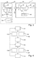
- Fig. 3 shows a system including a peripheral device, a controlled device and a host in accordance with another embodiment of the invention.
- the system 1 includes the peripheral device 40, the controlled device 20 and a host 70.
- the peripheral device 40 is arranged to be powered by the two terminals (second pair of terminals) of a USB compliant plug 50 other than the data terminal (V bus and Ground), wherein the V bus delivers +5 V against ground.
- the two data pins are used for the control signal and do not, in the mode where the controlled device is controlled, use the typical phy and uPnP technology of USB but a simpler information and signal transfer technology.
- the peripheral device generates a dim PWM signal (46) which is put to the data pins (first pair of terminals).
- the PWM signal 46 is sent over the Data+ pin 47.
- data pin Data- 48 is pulled up to Vbus by means of a resistor 49.
- the peripheral device 40 includes a light controller 42 that uses an external signal 43 e.g. from a presence detector to control the dim level from 75% to 30% when no person is detected.
- an external signal 43 e.g. from a presence detector to control the dim level from 75% to 30% when no person is detected.
- the overall circuitry of the peripheral device may be mounted on a PCB (not shown) which directly fits into a USB socket (see 34, 71) like a conventional USB stick.
- the controlled device 20 includes a lighting means 30, which is driven by a driver 32, which is powered by mains 10.
- the driver 32 is furthermore coupled to a socket 34 with four lines 35.
- two resistors 36, 37 are provided between the data lines and the ground.
- the host 70 is a conventional PC and also includes a USB socket 71. Besides PWM control also more complex communication from the peripheral device 40 to the luminaire 20 can be used in other implementation. It is conceived, for example, to put I2C signals on the two data pins of the connector, thus allowing for transferring multiple parameters and allowing for more sophisticated control techniques.
- differential DALI signals may be placed on the data pins and normal DALI lamp drivers may be controlled.
- UART signaling is used, where instead of the differential signaling (D+,D-) as in standard USB, the interface is mapped to receive/transmit (RX, TX) signal pairs.
- D+,D- differential signaling
- RX, TX receive/transmit
- Such signaling scheme is available in many low-cost micro-controllers (with small RAM and FLASH sizes) allowing bi-directional data flow: commands to the driver of the controlled device and sensed data to the peripheral device.
- a PWM control to dim the light may be generated by the MCU in the driver as a response to the command.
- Fig. 4 shows a flow diagram illustrating a method including a communication between a host and a peripheral device and a controlling of a controlled device by the peripheral device in accordance with an embodiment of the invention.
- the method discussed here applies, for example, to the system shown in Fig. 3 .
- the process starts with a first coupling step 101 of coupling the peripheral device and the host.
- the communication step 102 includes a first power receiving step 103 in which the peripheral device receives operating power from the host via a second pair of terminals of a plurality of terminals of the peripheral device.
- the peripheral device operates in a first mode and the communication step 102 further includes a first operation step 104 of communication between the peripheral device and the host in accordance with a predetermined standard via a first pair of terminals of the plurality of terminals.
- a first separation step 105 follows of separating the peripheral device and the host.
- the coupling in the first and the second coupling step 101, 106, respectively is provided by connecting a USB plug of the peripheral device to a corresponding USB socket of the host or the controlled device.
- a controlling step 107 follows, in which the peripheral device receives operating power from the controlled device via the second pair of terminals in a second power receiving step 108. Further, the peripheral device operates now in a second mode including a second operation step in which a control of the controlled device via at least two terminals of the first and second pair of terminals is provided, the control not being related to the operating power.
- the coupling between the controlled device and the peripheral device is ended in a second separation step 110, so that the peripheral device may again be coupled to the host (or another host or another controlled device).
- peripheral device is first connected to a host, e.g. for configuration, as the peripheral device may be commissioned during manufacturing, while nevertheless an on-site configuration (either initial or later on) is still possible.
- an on-site configuration either initial or later on
- the addition of network functionality to an existing lighting system requires a commissioning step, which ensures proper binding of physical luminaires with their representation in the network.
- controlled device is a device different from (an operating device of) a luminaire, as the invention is not limited as to the particular details of the controlled device.
- the invention allows, for example, for an alternative use of a USB-port (i.e. the physical configuration of the socket) which allows putting most of the cost on the USB-Module side and not on the side of the controlled device.
- a USB-port i.e. the physical configuration of the socket
- the USB ports as nearly cost-neutral addition to lamp drivers.
- Proper definition of the use of the pins of the USB port guarantees that "normal" USB hosts will not get harmed if the peripheral device modules get connected (e.g. in the wrong mode).
- a USB host will typically not be able to identify the device and make full use of these modules.
- USB modules will not get harmed when plugged into a luminaire (as an example of a controlled device) with reversed USB architecture, but (except for supply of USB power) there will be no functionality accessible to such USB module.
- the peripheral device gets power from the USB connector like known from state of the art USB.
- the peripheral device may use, for example, a PWM signal on the data pins which directly controls the PWM input of a lamp driver in the luminaire (as an example of a controlled device).
- the present invention provides for an exchangeability of the control means.
- Such exchangeability allows for easy upgrades of a luminaire (or other system in which the invention is employed) and easy configuration of the platform with an application dependant control means. This is accomplished by putting the control means into a module which is mechanically and electrically connected by means of a socket/plug means.
- the invention not only provides for the exchangeability, as the peripheral device uses the same physical features of the plug for communication with a host.
- a host e.g. a computer, may such configure the peripheral device based on such communication according to, for example, the USB standard.
- control signals provided by the peripheral device may be shared (in case of a class B) between different light engines (e.g. LED modules) with a light engine being controlled in the same way, while an addressing capability of, for example, the I2C bus in class C would allow even individual control of light engines in a luminaire.
- different light engines e.g. LED modules
- the peripheral device may be able to distinguish different lamp drivers (or controlled devices in general), e.g. by means of a signature impedance or through configuration via an NFC interface, in order to adapt the control signals on the (data) pins accordingly. This allows for using the same peripheral device with different controlled devices, automatically changing, for example, from PWM to I2C or DALI dependant on the recognized driver.
- managed "USB” Power Delivery may be used to guarantee that not compatible USB devices will not get power from the controlled device.
- the simple interface is used to verify if the plug-in device is allowed to communicate to the driver according to the present invention and power is interrupted if the device is not a compatible one.
- the verification process starts by checking if a device is connected to the "USB" port by sensing the current that is drawn. Following this, the driver of the controlled device checks for a special signature from the peripheral device that should come within a predefined interval from the moment port connection is detected.
- Another way of verification is by checking if the reply for an interrogation results in the correct response.
- Power disconnection may be realized by disabling the power regulator or disconnecting the "USB" power line using a power switch.
- Power re-connection may be achieved by checking if the current drawn from the port has decreased below a certain threshold.
- analog control techniques can be used. For example, it is possible to use the voltage (referenced by the GND pin) on one or both digital signal pins Data+ (UPIN2) and Data- (UPIN3) for a signaling voltage. For this beneficially the signal to control the driver linearly is in the forbidden range of digital signals e.g. 0.7V to 3.7V and would be undefined for a digital input.
- UPIN2 3.7V means 100% light intensity (lamp is fully on).
- Resistors on the lamp driver side UPIN2 may be used to guarantee that if no peripheral device is connected the voltage UPIN2 is above 3.7V and hence the driver will be always fully on.
- mappings of voltages UPIN2 and UPIN3 to the lamp control are possible. For example by extending these over the above listed dimming levels to color or color temperature can also be defined.
- the set-point signal(s) received from the USB host e.g. PWM dimming pattern
- a locally derived signal might be sent in an isolating manner to the feedback controller of the driver, e.g. via an opto-coupler.
- a small additional transistor may periodically interrupt the auxiliary power transfer, which in connection with the filter on the isolated end results in a modulation of the 5 V supply that can be sensed by the peripheral device.
- the interruption pulse width could be modulated which controls the amplitude of the modulation added to the 5 V supply (e.g. 50 ... 500 mV).
- the interruption frequency can as well or in addition be used (e.g.1Hz ... 10Hz).
- Examples of functionality the peripheral device according to the invention may bring to the controlled device, e.g. the luminaire include (but are not limited to) a wireless range extender e.g. for WiFi, a wireless bridge e.g. between WiFi and ZigBee; a sensing function for local control of the LED driver, sensing and connectivity functions as part of a sensor network, connectivity-enabled control functions, connectivity-enabled control and data retrieval functions, an IR receiver for luminaire control, a wireless loudspeaker, a low bit rate (event-based) wireless (e.g.
- WiFi Wireless Fidelity
- this can be used to support sensing functions with low data rate output
- a wireless low-power camera module a upgrade kit to turn a simple analogue driver into a digital driver, and a wireless CodedLight module that upgrades the existing luminaire driver into a CodedLight-enabled driver.
- a single processor, device or other unit may fulfill the functions of several items recited in the claims.
- the mere fact that certain measures are recited in mutually different dependent claims does not indicate that a combination of these measures cannot be used to advantage.
- Operations like communicating, controlling, outputting, mode switching, detecting, sensing, and coupling etc. can be implemented as program code means of a computer program and/or as dedicated hardware.
- a computer program may be stored and/or distributed on a suitable medium, such as an optical storage medium or a solid-state medium, supplied together with or as part of other hardware, but may also be distributed in other forms, such as via the Internet or other wired or wireless telecommunication systems.
- a suitable medium such as an optical storage medium or a solid-state medium, supplied together with or as part of other hardware, but may also be distributed in other forms, such as via the Internet or other wired or wireless telecommunication systems.
Landscapes
- Engineering & Computer Science (AREA)
- Theoretical Computer Science (AREA)
- General Engineering & Computer Science (AREA)
- Physics & Mathematics (AREA)
- General Physics & Mathematics (AREA)
- Computer Networks & Wireless Communication (AREA)
- Computer Hardware Design (AREA)
- Circuit Arrangement For Electric Light Sources In General (AREA)
- Selective Calling Equipment (AREA)
Claims (13)
- Peripherievorrichtung (40) zur Kommunikation mit einem Host (70) und zum Steuern einer gesteuerten Vorrichtung (20), umfassend:- eine Vielzahl von Klemmen (50, 50A-D), die ein erstes Klemmenpaar (50B, 50C) und ein zweites Klemmenpaar (50A, 50D) beinhaltet,- eine Kommunikationseinheit (42), die mit dem ersten Klemmenpaar (50B, 50C) gekoppelt ist,- eine Steuereinheit (42), die mit mindestens zwei Klemmen (50B, 50C) des ersten und zweiten Klemmenpaares (50, 50A-D) gekoppelt ist, dadurch gekennzeichnet, dass die Peripherievorrichtung weiter umfasst- eine Erfassungseinheit (61), die angeordnet ist, um zu erfassen, ob die Peripherievorrichtung (40) mit dem Host (70) oder mit der gesteuerten Vorrichtung (20) verbunden ist,
wobei die Peripherievorrichtung (40) angeordnet ist, um Betriebsleistung über das zweite Klemmenpaar (50A, 50D) zu empfangen,
wobei die Peripherievorrichtung (40) weiter angeordnet ist, um selektiv in mindestens einem ersten Modus und einem zweiten Modus zu arbeiten,- wobei der erste Modus ein Modus ist, in dem die Kommunikationseinheit (42) zum Kommunizieren mit dem Host (70) gemäß einem vorbestimmten Standard betreibbar ist und die Peripherievorrichtung (40) zum Empfangen der Betriebsleistung von dem Host (70) angeordnet ist, und- wobei der zweite Modus ein Modus ist, in dem die Steuereinheit (42) zum Steuern der gesteuerten Vorrichtung (20) betreibbar ist, wobei die Steuerung nicht mit der Betriebsleistung zusammenhängt, und die Peripherievorrichtung (40) zum Empfangen der Betriebsleistung von der gesteuerten Vorrichtung (20) angeordnet ist,wobei die Erfassungseinheit (61) angeordnet ist, um die Peripherievorrichtung (40) zu steuern, um basierend auf einem Ergebnis der Erfassung zwischen dem ersten und zweiten Modus umzuschalten. - Peripherievorrichtung (40) nach Anspruch 1, wobei die Steuereinheit (42) angeordnet ist, um eines von einem Analogsignal, einem pulsbreitenmodulierten Signal und einem digitalen Signal an die gesteuerte Vorrichtung über die mindestens zwei Klemmen (50B, 50C) auszugeben.
- Peripherievorrichtung (40) nach Anspruch 1, umfassend:einen Schalter (63), um zu bewirken, dass die Peripherievorrichtung in dem ersten Modus arbeitet, wenn sich der Schalter (63) in einem ersten Zustand befindet, und um zu bewirken, dass die Peripherievorrichtung in dem zweiten Modus arbeitet, wenn sich der Schalter (63) in einem zweiten Zustand befindet; wobeidie Erfassungseinheit (61) angeordnet ist, um zu erfassen, ob die Peripherievorrichtung (40) mit dem Host (70) oder mit der gesteuerten Vorrichtung (20) verbunden ist, wobei die Erfassungseinheit (61) angeordnet ist, um die Peripherievorrichtung (40) für einen Modus zu steuern, der basierend auf einem Ergebnis der Erfassung in den ersten oder zweiten Modus umschaltet, wenn sich der Schalter (63) in einem dritten Zustand befindet.
- Peripherievorrichtung (40) nach Anspruch 1, umfassend:
einen Sensor (44) und/oder eine mit der Steuereinheit (42) gekoppelte Kommunikationsschnittstelle (45), wobei die Steuereinheit (42) zum Steuern der gesteuerten Vorrichtung (20) gemäß einem Eingang vom Sensor (44) und/oder der Kommunikationsschnittstelle (45) angeordnet ist. - Peripherievorrichtung (40) nach Anspruch 1, wobei der vorbestimmte Standard ein USB-Standard oder ein IEEE 1394-Standard ist.
- Peripherievorrichtung (40) nach Anspruch 1, umfassend:
eine Empfangseinheit (62), die mit der Vielzahl von Klemmen (50, 50A-D) gekoppelt ist, wobei die Empfangseinheit (62) angeordnet ist, um von der gesteuerten Vorrichtung (20) über die Vielzahl von Klemmen (50, 50A-50D) übertragene Informationen zu empfangen. - Peripherievorrichtung (40) nach Anspruch 6, wobei die Empfangseinheit (62) mit dem zweiten Klemmenpaar (50A, 50D) gekoppelt und angeordnet ist, um gesendete Informationen aus einer Änderung der zugeführten Betriebsleistung zu erfassen.
- System (1), das die Peripherievorrichtung (40) nach Anspruch 1 und eine gesteuerte Vorrichtung (20) beinhaltet,
wobei die gesteuerte Vorrichtung (20) eine Vielzahl von Vorrichtungs-Klemmen (34) zum Koppeln mit der Vielzahl von Klemmen (50, 50A-50D) der Peripherievorrichtung (40), eine Stromversorgungseinheit (32) zum Zuführen von Betriebsleistung zu der Peripherievorrichtung (40) über das zweite Klemmenpaar (50A, 50D) und eine Betriebsschaltung (32) zum Koppeln und Steuern durch die Steuereinheit (42) der Peripherievorrichtung (40) beinhaltet. - System (1) nach Anspruch 8, weiter umfassend einen Host (70), der zur Kommunikation mit der Peripherievorrichtung (40) gemäß dem vorbestimmten Standard angeordnet ist.
- System (1) nach Anspruch 8, wobei die Peripherievorrichtung (40) und die gesteuerte Vorrichtung (20) gemeinsam eine Betriebsschaltung (32, 35, 42, 47, 48) zum Betreiben einer Betriebseinheit (30) der gesteuerten Vorrichtung (20) umfassen, wobei ein erster Abschnitt (42, 47, 48) der Betriebsschaltung in der Peripherievorrichtung (40) bereitgestellt ist und ein zweiter Abschnitt (32, 35) der Betriebsschaltung in der Steuervorrichtung (20) bereitgestellt ist.
- System (1) nach Anspruch 8, wobei die gesteuerte Vorrichtung (20) eine Leuchte ist.
- Verfahren, das eine Kommunikation zwischen einem Host (70) und einer Peripherievorrichtung (40) und eine Steuerung einer durch die Peripherievorrichtung (40) gesteuerten Vorrichtung (20) beinhaltet, wobei das Verfahren umfasst:- einen ersten Kopplungsschritt (101) zum Koppeln der Peripherievorrichtung (40) und des Hosts (70),- Erfassen über eine Erfassungseinheit (61), dass die Peripherievorrichtung (40) mit dem Host (70) verbunden ist,- einen Kommunikationsschritt (102), in dem die Peripherievorrichtung (40) über ein zweites Klemmenpaar (50A, 50D) einer Vielzahl von Klemmen (50, 50A-50D) der Peripherievorrichtung (40) Betriebsleistung vom Host (70) empfängt (103) und in einem ersten Modus arbeitet, der eine Kommunikation (104) zwischen der Peripherievorrichtung (40) und dem Host (70) gemäß einem vorbestimmten Standard über ein erstes Klemmenpaar (50B, 50C) der Vielzahl von Klemmen (50, 50A-50D) beinhaltet,- einen Trennungsschritt (105) zum Trennen der Peripherievorrichtung (40) und des Hosts (70),- einen zweiten Kopplungsschritt (106) zum Koppeln der Peripherievorrichtung (40) und der gesteuerten Vorrichtung (20),- Erfassen über eine Erfassungseinheit (61), dass die Peripherievorrichtung (40) mit der gesteuerten Vorrichtung (20) verbunden ist, und- einen Steuerungsschritt (107), in dem die Peripherievorrichtung (40) über das zweite Klemmenpaar (50A, 50D) Betriebsleistung von der gesteuerten Vorrichtung (20) empfängt (107) und in einem zweiten Modus arbeitet, der eine Steuerung (109) der gesteuerten Vorrichtung (20) über mindestens zwei Klemmen (50B, 50C) des ersten und zweiten Klemmenpaares (50, 50A-D) beinhaltet, wobei die Steuerung nicht mit der Betriebsleistung verbunden ist.
- Softwareprodukt für eine Peripherievorrichtung (40), wobei das Softwareprodukt Programmcodemittel umfasst, um die Peripherievorrichtung (40) nach Anspruch 1 zu veranlassen, die Schritte des Verfahrens nach Anspruch 12 auszuführen, wenn das Softwareprodukt auf der Peripherievorrichtung (40) ausgeführt wird.
Applications Claiming Priority (2)
| Application Number | Priority Date | Filing Date | Title |
|---|---|---|---|
| EP16152902 | 2016-01-27 | ||
| PCT/EP2017/051312 WO2017129517A1 (en) | 2016-01-27 | 2017-01-23 | Peripheral device, system including the peripheral device and method |
Publications (2)
| Publication Number | Publication Date |
|---|---|
| EP3409080A1 EP3409080A1 (de) | 2018-12-05 |
| EP3409080B1 true EP3409080B1 (de) | 2019-08-21 |
Family
ID=55262721
Family Applications (1)
| Application Number | Title | Priority Date | Filing Date |
|---|---|---|---|
| EP17701684.7A Active EP3409080B1 (de) | 2016-01-27 | 2017-01-23 | Periphere vorrichtung, system mit der peripheren vorrichtung und verfahren |
Country Status (5)
| Country | Link |
|---|---|
| US (1) | US11397693B2 (de) |
| EP (1) | EP3409080B1 (de) |
| JP (1) | JP6779999B2 (de) |
| CN (1) | CN108702830B (de) |
| WO (1) | WO2017129517A1 (de) |
Families Citing this family (2)
| Publication number | Priority date | Publication date | Assignee | Title |
|---|---|---|---|---|
| US10320180B1 (en) * | 2018-04-24 | 2019-06-11 | Cypress Semiconductor Corporation | Current control and protection for universal serial bus type-C (USB-C) connector systems |
| CN114034979A (zh) * | 2021-11-12 | 2022-02-11 | 昆明理工大学 | 一种交流输电线路测距方法及系统 |
Family Cites Families (30)
| Publication number | Priority date | Publication date | Assignee | Title |
|---|---|---|---|---|
| US6357011B2 (en) | 1998-07-15 | 2002-03-12 | Gateway, Inc. | Bus-powered computer peripheral with supplement battery power to overcome bus-power limit |
| US6804727B1 (en) * | 2001-02-23 | 2004-10-12 | Lexmark International, Inc. | Method for communication from a host computer to a peripheral device |
| GB2375273B (en) | 2001-04-30 | 2004-07-07 | Nokia Mobile Phones Ltd | Communication interface for an electronic device |
| JP2002366284A (ja) * | 2001-06-08 | 2002-12-20 | Alps Electric Co Ltd | 携帯電子機器用キーボード装置及び充電装置 |
| US7126585B2 (en) | 2001-08-17 | 2006-10-24 | Jeffery Davis | One chip USB optical mouse sensor solution |
| KR100444702B1 (ko) * | 2002-04-18 | 2004-08-16 | 삼성전자주식회사 | 고속 범용 직렬 버스 인터페이스를 지원하는 디지탈가입자 회선 모뎀 |
| US6732218B2 (en) * | 2002-07-26 | 2004-05-04 | Motorola, Inc. | Dual-role compatible USB hub device and method |
| EP1609048A4 (de) * | 2003-03-27 | 2009-01-14 | Milsys Ltd | Datenspeichereinrichtung mit vollem zugang durch alle benutzer |
| US7441053B2 (en) * | 2003-12-15 | 2008-10-21 | Nokia Corporation | Support of an interaction between a host device and a peripheral device |
| US8469808B2 (en) * | 2004-01-15 | 2013-06-25 | Bgc Partners, Inc. | System and method for managing a game controller device for electronic trading |
| US20050170699A1 (en) * | 2004-02-03 | 2005-08-04 | Overtoom Eric J. | USB OTG adapter module for debugging USB OTG devices |
| TW200513865A (en) * | 2004-09-17 | 2005-04-16 | Via Tech Inc | USB control circuit with function of switching between host mode and controlled mode and its operating method |
| KR101329307B1 (ko) * | 2007-01-25 | 2013-11-13 | 삼성전자주식회사 | Usb 동작을 제어하는 장치 및 방법 |
| CN100533419C (zh) | 2007-03-13 | 2009-08-26 | 威盛电子股份有限公司 | Usb外围设备和其模式侦测方法 |
| US7717607B2 (en) * | 2007-10-30 | 2010-05-18 | General Dynamics Itronix Corporation | System and apparatus for keyboard illumination |
| US8296486B2 (en) * | 2008-03-17 | 2012-10-23 | International Business Machines Corporation | Peripheral device enabling enhanced communication |
| US8421779B2 (en) | 2008-05-29 | 2013-04-16 | Himax Technologies Limited | Display and method thereof for signal transmission |
| US9208118B2 (en) * | 2008-06-10 | 2015-12-08 | Lg Electronics Inc. | Communication device, a method of processing signal in the communication device and a system having the communication device |
| US8330586B2 (en) | 2009-02-24 | 2012-12-11 | Marvell World Trade Ltd. | Systems and methods for programming of a cooling fan via a serial port communication mode |
| US20130191568A1 (en) | 2012-01-23 | 2013-07-25 | Qualcomm Incorporated | Operating m-phy based communications over universal serial bus (usb) interface, and related cables, connectors, systems and methods |
| US10219338B2 (en) * | 2012-07-01 | 2019-02-26 | Cree, Inc. | Modular lighting control |
| CN202791496U (zh) | 2012-09-06 | 2013-03-13 | 昆明理工大学 | 一种可调光型usb灯具 |
| US8909815B2 (en) * | 2012-11-07 | 2014-12-09 | Analogix Semiconductor, Inc. | Devices and methods for multiple data streams over USB 2.0 |
| KR101999660B1 (ko) * | 2012-11-08 | 2019-10-01 | 엘지이노텍 주식회사 | 통신 모듈을 포함하는 조명 장치 |
| EP2935988B1 (de) * | 2012-12-18 | 2019-01-30 | Cree, Inc. | Leuchte für verteilte steuerung |
| US9244876B2 (en) * | 2012-12-20 | 2016-01-26 | Blackberry Limited | Method and apparatus pertaining to universal serial bus-based charging |
| CN103309308B (zh) * | 2013-05-17 | 2016-08-10 | 华为技术有限公司 | 一种设备智能化控制方法及装置、系统、即插即用设备 |
| US9460037B2 (en) * | 2013-09-26 | 2016-10-04 | Delphi Technologies, Inc. | Flexible mobile device connectivity to automotive systems with USB hubs |
| JP2015095420A (ja) * | 2013-11-13 | 2015-05-18 | パナソニックIpマネジメント株式会社 | 照明制御装置及び照明システム |
| CN104021101A (zh) | 2014-05-09 | 2014-09-03 | 深圳市汇川控制技术有限公司 | 基于lpc1768平台的usb接口系统及实现方法 |
-
2017
- 2017-01-23 US US16/069,513 patent/US11397693B2/en active Active
- 2017-01-23 JP JP2018531160A patent/JP6779999B2/ja active Active
- 2017-01-23 CN CN201780008909.3A patent/CN108702830B/zh active Active
- 2017-01-23 WO PCT/EP2017/051312 patent/WO2017129517A1/en unknown
- 2017-01-23 EP EP17701684.7A patent/EP3409080B1/de active Active
Non-Patent Citations (1)
| Title |
|---|
| None * |
Also Published As
| Publication number | Publication date |
|---|---|
| WO2017129517A1 (en) | 2017-08-03 |
| US20190012277A1 (en) | 2019-01-10 |
| US11397693B2 (en) | 2022-07-26 |
| JP6779999B2 (ja) | 2020-11-04 |
| CN108702830A (zh) | 2018-10-23 |
| EP3409080A1 (de) | 2018-12-05 |
| JP2019509582A (ja) | 2019-04-04 |
| CN108702830B (zh) | 2021-07-13 |
Similar Documents
| Publication | Publication Date | Title |
|---|---|---|
| US10694609B2 (en) | Wireless lighting control | |
| JP7564412B2 (ja) | 電圧源能力の動的学習 | |
| US8626318B2 (en) | Lamp device | |
| JP5383924B2 (ja) | 電子変換器の動作の制御方法、対応する電子変換器、照明システムおよびソフトウェア製品 | |
| US10561007B2 (en) | Inline wireless module | |
| US20090167494A1 (en) | Intelligent Power Cord Device ( iCord) | |
| US9746138B1 (en) | Modular lighting and ancillary component apparatus and system | |
| CN114095477B (zh) | 用于对串联连接的从设备进行自动寻址的系统、设备和方法 | |
| DK3210273T3 (en) | CONTROL OF POWER CONSUMPTION IN APPLIANCES | |
| CN110769559A (zh) | 一种多接口兼容复用的通信、调光及编程系统 | |
| EP3409080B1 (de) | Periphere vorrichtung, system mit der peripheren vorrichtung und verfahren | |
| US8384312B2 (en) | Power distribution system for supplying electrical power to a plurality of lighting units | |
| WO2017129490A1 (en) | System and method for modular control | |
| CN203193764U (zh) | 一种带有指示灯的监控摄像机 | |
| JP2009508411A (ja) | ネットワークにおけるケーブルインタフェース接続を監視するシステム | |
| KR101678556B1 (ko) | Usb 다중 접속 제어 장치 | |
| US8540522B2 (en) | Utility control system and method | |
| KR102109561B1 (ko) | 복수의 커넥터 결합부를 통한 모듈 확장 가능한 컨버터를 포함하는 조명 장치 | |
| TWI792840B (zh) | Usb晶片及其操作方法 | |
| CN109240262A (zh) | 总线电路以及智能货架系统 | |
| US20220232154A1 (en) | Identification/Communication Interface Between Consumer Electronic Devices and Accessory Devices | |
| CN203482464U (zh) | 一种led灯具通信控制桥接器 | |
| KR20190123968A (ko) | 플러그앤 플레이 기능이 포함된 스마트 조명 장치 및 그 제어방법 |
Legal Events
| Date | Code | Title | Description |
|---|---|---|---|
| STAA | Information on the status of an ep patent application or granted ep patent |
Free format text: STATUS: UNKNOWN |
|
| STAA | Information on the status of an ep patent application or granted ep patent |
Free format text: STATUS: THE INTERNATIONAL PUBLICATION HAS BEEN MADE |
|
| PUAI | Public reference made under article 153(3) epc to a published international application that has entered the european phase |
Free format text: ORIGINAL CODE: 0009012 |
|
| STAA | Information on the status of an ep patent application or granted ep patent |
Free format text: STATUS: REQUEST FOR EXAMINATION WAS MADE |
|
| 17P | Request for examination filed |
Effective date: 20180827 |
|
| AK | Designated contracting states |
Kind code of ref document: A1 Designated state(s): AL AT BE BG CH CY CZ DE DK EE ES FI FR GB GR HR HU IE IS IT LI LT LU LV MC MK MT NL NO PL PT RO RS SE SI SK SM TR |
|
| AX | Request for extension of the european patent |
Extension state: BA ME |
|
| RAP1 | Party data changed (applicant data changed or rights of an application transferred) |
Owner name: PHILIPS LIGHTING HOLDING B.V. |
|
| GRAP | Despatch of communication of intention to grant a patent |
Free format text: ORIGINAL CODE: EPIDOSNIGR1 |
|
| STAA | Information on the status of an ep patent application or granted ep patent |
Free format text: STATUS: GRANT OF PATENT IS INTENDED |
|
| INTG | Intention to grant announced |
Effective date: 20190205 |
|
| RAP1 | Party data changed (applicant data changed or rights of an application transferred) |
Owner name: SIGNIFY HOLDING B.V. |
|
| DAV | Request for validation of the european patent (deleted) | ||
| DAX | Request for extension of the european patent (deleted) | ||
| GRAS | Grant fee paid |
Free format text: ORIGINAL CODE: EPIDOSNIGR3 |
|
| GRAA | (expected) grant |
Free format text: ORIGINAL CODE: 0009210 |
|
| STAA | Information on the status of an ep patent application or granted ep patent |
Free format text: STATUS: THE PATENT HAS BEEN GRANTED |
|
| AK | Designated contracting states |
Kind code of ref document: B1 Designated state(s): AL AT BE BG CH CY CZ DE DK EE ES FI FR GB GR HR HU IE IS IT LI LT LU LV MC MK MT NL NO PL PT RO RS SE SI SK SM TR |
|
| REG | Reference to a national code |
Ref country code: GB Ref legal event code: FG4D |
|
| REG | Reference to a national code |
Ref country code: CH Ref legal event code: EP |
|
| REG | Reference to a national code |
Ref country code: DE Ref legal event code: R096 Ref document number: 602017006377 Country of ref document: DE |
|
| REG | Reference to a national code |
Ref country code: AT Ref legal event code: REF Ref document number: 1171231 Country of ref document: AT Kind code of ref document: T Effective date: 20190915 |
|
| REG | Reference to a national code |
Ref country code: IE Ref legal event code: FG4D |
|
| REG | Reference to a national code |
Ref country code: LT Ref legal event code: MG4D |
|
| REG | Reference to a national code |
Ref country code: NL Ref legal event code: MP Effective date: 20190821 |
|
| PG25 | Lapsed in a contracting state [announced via postgrant information from national office to epo] |
Ref country code: HR Free format text: LAPSE BECAUSE OF FAILURE TO SUBMIT A TRANSLATION OF THE DESCRIPTION OR TO PAY THE FEE WITHIN THE PRESCRIBED TIME-LIMIT Effective date: 20190821 Ref country code: NL Free format text: LAPSE BECAUSE OF FAILURE TO SUBMIT A TRANSLATION OF THE DESCRIPTION OR TO PAY THE FEE WITHIN THE PRESCRIBED TIME-LIMIT Effective date: 20190821 Ref country code: SE Free format text: LAPSE BECAUSE OF FAILURE TO SUBMIT A TRANSLATION OF THE DESCRIPTION OR TO PAY THE FEE WITHIN THE PRESCRIBED TIME-LIMIT Effective date: 20190821 Ref country code: PT Free format text: LAPSE BECAUSE OF FAILURE TO SUBMIT A TRANSLATION OF THE DESCRIPTION OR TO PAY THE FEE WITHIN THE PRESCRIBED TIME-LIMIT Effective date: 20191223 Ref country code: BG Free format text: LAPSE BECAUSE OF FAILURE TO SUBMIT A TRANSLATION OF THE DESCRIPTION OR TO PAY THE FEE WITHIN THE PRESCRIBED TIME-LIMIT Effective date: 20191121 Ref country code: LT Free format text: LAPSE BECAUSE OF FAILURE TO SUBMIT A TRANSLATION OF THE DESCRIPTION OR TO PAY THE FEE WITHIN THE PRESCRIBED TIME-LIMIT Effective date: 20190821 Ref country code: FI Free format text: LAPSE BECAUSE OF FAILURE TO SUBMIT A TRANSLATION OF THE DESCRIPTION OR TO PAY THE FEE WITHIN THE PRESCRIBED TIME-LIMIT Effective date: 20190821 Ref country code: NO Free format text: LAPSE BECAUSE OF FAILURE TO SUBMIT A TRANSLATION OF THE DESCRIPTION OR TO PAY THE FEE WITHIN THE PRESCRIBED TIME-LIMIT Effective date: 20191121 |
|
| PG25 | Lapsed in a contracting state [announced via postgrant information from national office to epo] |
Ref country code: RS Free format text: LAPSE BECAUSE OF FAILURE TO SUBMIT A TRANSLATION OF THE DESCRIPTION OR TO PAY THE FEE WITHIN THE PRESCRIBED TIME-LIMIT Effective date: 20190821 Ref country code: IS Free format text: LAPSE BECAUSE OF FAILURE TO SUBMIT A TRANSLATION OF THE DESCRIPTION OR TO PAY THE FEE WITHIN THE PRESCRIBED TIME-LIMIT Effective date: 20191221 Ref country code: GR Free format text: LAPSE BECAUSE OF FAILURE TO SUBMIT A TRANSLATION OF THE DESCRIPTION OR TO PAY THE FEE WITHIN THE PRESCRIBED TIME-LIMIT Effective date: 20191122 Ref country code: ES Free format text: LAPSE BECAUSE OF FAILURE TO SUBMIT A TRANSLATION OF THE DESCRIPTION OR TO PAY THE FEE WITHIN THE PRESCRIBED TIME-LIMIT Effective date: 20190821 Ref country code: AL Free format text: LAPSE BECAUSE OF FAILURE TO SUBMIT A TRANSLATION OF THE DESCRIPTION OR TO PAY THE FEE WITHIN THE PRESCRIBED TIME-LIMIT Effective date: 20190821 Ref country code: LV Free format text: LAPSE BECAUSE OF FAILURE TO SUBMIT A TRANSLATION OF THE DESCRIPTION OR TO PAY THE FEE WITHIN THE PRESCRIBED TIME-LIMIT Effective date: 20190821 |
|
| REG | Reference to a national code |
Ref country code: AT Ref legal event code: MK05 Ref document number: 1171231 Country of ref document: AT Kind code of ref document: T Effective date: 20190821 |
|
| PG25 | Lapsed in a contracting state [announced via postgrant information from national office to epo] |
Ref country code: TR Free format text: LAPSE BECAUSE OF FAILURE TO SUBMIT A TRANSLATION OF THE DESCRIPTION OR TO PAY THE FEE WITHIN THE PRESCRIBED TIME-LIMIT Effective date: 20190821 |
|
| PG25 | Lapsed in a contracting state [announced via postgrant information from national office to epo] |
Ref country code: DK Free format text: LAPSE BECAUSE OF FAILURE TO SUBMIT A TRANSLATION OF THE DESCRIPTION OR TO PAY THE FEE WITHIN THE PRESCRIBED TIME-LIMIT Effective date: 20190821 Ref country code: AT Free format text: LAPSE BECAUSE OF FAILURE TO SUBMIT A TRANSLATION OF THE DESCRIPTION OR TO PAY THE FEE WITHIN THE PRESCRIBED TIME-LIMIT Effective date: 20190821 Ref country code: EE Free format text: LAPSE BECAUSE OF FAILURE TO SUBMIT A TRANSLATION OF THE DESCRIPTION OR TO PAY THE FEE WITHIN THE PRESCRIBED TIME-LIMIT Effective date: 20190821 Ref country code: IT Free format text: LAPSE BECAUSE OF FAILURE TO SUBMIT A TRANSLATION OF THE DESCRIPTION OR TO PAY THE FEE WITHIN THE PRESCRIBED TIME-LIMIT Effective date: 20190821 Ref country code: RO Free format text: LAPSE BECAUSE OF FAILURE TO SUBMIT A TRANSLATION OF THE DESCRIPTION OR TO PAY THE FEE WITHIN THE PRESCRIBED TIME-LIMIT Effective date: 20190821 Ref country code: PL Free format text: LAPSE BECAUSE OF FAILURE TO SUBMIT A TRANSLATION OF THE DESCRIPTION OR TO PAY THE FEE WITHIN THE PRESCRIBED TIME-LIMIT Effective date: 20190821 |
|
| PG25 | Lapsed in a contracting state [announced via postgrant information from national office to epo] |
Ref country code: SM Free format text: LAPSE BECAUSE OF FAILURE TO SUBMIT A TRANSLATION OF THE DESCRIPTION OR TO PAY THE FEE WITHIN THE PRESCRIBED TIME-LIMIT Effective date: 20190821 Ref country code: IS Free format text: LAPSE BECAUSE OF FAILURE TO SUBMIT A TRANSLATION OF THE DESCRIPTION OR TO PAY THE FEE WITHIN THE PRESCRIBED TIME-LIMIT Effective date: 20200224 Ref country code: SK Free format text: LAPSE BECAUSE OF FAILURE TO SUBMIT A TRANSLATION OF THE DESCRIPTION OR TO PAY THE FEE WITHIN THE PRESCRIBED TIME-LIMIT Effective date: 20190821 Ref country code: CZ Free format text: LAPSE BECAUSE OF FAILURE TO SUBMIT A TRANSLATION OF THE DESCRIPTION OR TO PAY THE FEE WITHIN THE PRESCRIBED TIME-LIMIT Effective date: 20190821 |
|
| REG | Reference to a national code |
Ref country code: DE Ref legal event code: R097 Ref document number: 602017006377 Country of ref document: DE |
|
| PLBE | No opposition filed within time limit |
Free format text: ORIGINAL CODE: 0009261 |
|
| STAA | Information on the status of an ep patent application or granted ep patent |
Free format text: STATUS: NO OPPOSITION FILED WITHIN TIME LIMIT |
|
| PG2D | Information on lapse in contracting state deleted |
Ref country code: IS |
|
| 26N | No opposition filed |
Effective date: 20200603 |
|
| PG25 | Lapsed in a contracting state [announced via postgrant information from national office to epo] |
Ref country code: MC Free format text: LAPSE BECAUSE OF FAILURE TO SUBMIT A TRANSLATION OF THE DESCRIPTION OR TO PAY THE FEE WITHIN THE PRESCRIBED TIME-LIMIT Effective date: 20190821 |
|
| REG | Reference to a national code |
Ref country code: CH Ref legal event code: PL |
|
| REG | Reference to a national code |
Ref country code: BE Ref legal event code: MM Effective date: 20200131 |
|
| PG25 | Lapsed in a contracting state [announced via postgrant information from national office to epo] |
Ref country code: LU Free format text: LAPSE BECAUSE OF NON-PAYMENT OF DUE FEES Effective date: 20200123 |
|
| PG25 | Lapsed in a contracting state [announced via postgrant information from national office to epo] |
Ref country code: LI Free format text: LAPSE BECAUSE OF NON-PAYMENT OF DUE FEES Effective date: 20200131 Ref country code: BE Free format text: LAPSE BECAUSE OF NON-PAYMENT OF DUE FEES Effective date: 20200131 Ref country code: CH Free format text: LAPSE BECAUSE OF NON-PAYMENT OF DUE FEES Effective date: 20200131 |
|
| PG25 | Lapsed in a contracting state [announced via postgrant information from national office to epo] |
Ref country code: IE Free format text: LAPSE BECAUSE OF NON-PAYMENT OF DUE FEES Effective date: 20200123 |
|
| PG25 | Lapsed in a contracting state [announced via postgrant information from national office to epo] |
Ref country code: MT Free format text: LAPSE BECAUSE OF FAILURE TO SUBMIT A TRANSLATION OF THE DESCRIPTION OR TO PAY THE FEE WITHIN THE PRESCRIBED TIME-LIMIT Effective date: 20190821 Ref country code: CY Free format text: LAPSE BECAUSE OF FAILURE TO SUBMIT A TRANSLATION OF THE DESCRIPTION OR TO PAY THE FEE WITHIN THE PRESCRIBED TIME-LIMIT Effective date: 20190821 |
|
| PG25 | Lapsed in a contracting state [announced via postgrant information from national office to epo] |
Ref country code: MK Free format text: LAPSE BECAUSE OF FAILURE TO SUBMIT A TRANSLATION OF THE DESCRIPTION OR TO PAY THE FEE WITHIN THE PRESCRIBED TIME-LIMIT Effective date: 20190821 |
|
| P01 | Opt-out of the competence of the unified patent court (upc) registered |
Effective date: 20230425 |
|
| PG25 | Lapsed in a contracting state [announced via postgrant information from national office to epo] |
Ref country code: SI Free format text: LAPSE BECAUSE OF FAILURE TO SUBMIT A TRANSLATION OF THE DESCRIPTION OR TO PAY THE FEE WITHIN THE PRESCRIBED TIME-LIMIT Effective date: 20190821 |
|
| PGFP | Annual fee paid to national office [announced via postgrant information from national office to epo] |
Ref country code: DE Payment date: 20240328 Year of fee payment: 8 Ref country code: GB Payment date: 20240123 Year of fee payment: 8 |
|
| PGFP | Annual fee paid to national office [announced via postgrant information from national office to epo] |
Ref country code: FR Payment date: 20240125 Year of fee payment: 8 |