EP3408901B1 - Vorrichtung und verfahren zur optischen isolierung - Google Patents
Vorrichtung und verfahren zur optischen isolierung Download PDFInfo
- Publication number
- EP3408901B1 EP3408901B1 EP17704521.8A EP17704521A EP3408901B1 EP 3408901 B1 EP3408901 B1 EP 3408901B1 EP 17704521 A EP17704521 A EP 17704521A EP 3408901 B1 EP3408901 B1 EP 3408901B1
- Authority
- EP
- European Patent Office
- Prior art keywords
- laser
- optical
- optical fibre
- length
- radiation
- Prior art date
- Legal status (The legal status is an assumption and is not a legal conclusion. Google has not performed a legal analysis and makes no representation as to the accuracy of the status listed.)
- Active
Links
Images


Classifications
-
- H—ELECTRICITY
- H01—ELECTRIC ELEMENTS
- H01S—DEVICES USING THE PROCESS OF LIGHT AMPLIFICATION BY STIMULATED EMISSION OF RADIATION [LASER] TO AMPLIFY OR GENERATE LIGHT; DEVICES USING STIMULATED EMISSION OF ELECTROMAGNETIC RADIATION IN WAVE RANGES OTHER THAN OPTICAL
- H01S3/00—Lasers, i.e. devices using stimulated emission of electromagnetic radiation in the infrared, visible or ultraviolet wave range
- H01S3/005—Optical devices external to the laser cavity, specially adapted for lasers, e.g. for homogenisation of the beam or for manipulating laser pulses, e.g. pulse shaping
- H01S3/0064—Anti-reflection devices, e.g. optical isolaters
-
- B—PERFORMING OPERATIONS; TRANSPORTING
- B23—MACHINE TOOLS; METAL-WORKING NOT OTHERWISE PROVIDED FOR
- B23K—SOLDERING OR UNSOLDERING; WELDING; CLADDING OR PLATING BY SOLDERING OR WELDING; CUTTING BY APPLYING HEAT LOCALLY, e.g. FLAME CUTTING; WORKING BY LASER BEAM
- B23K26/00—Working by laser beam, e.g. welding, cutting or boring
- B23K26/02—Positioning or observing the workpiece, e.g. with respect to the point of impact; Aligning, aiming or focusing the laser beam
- B23K26/06—Shaping the laser beam, e.g. by masks or multi-focusing
- B23K26/064—Shaping the laser beam, e.g. by masks or multi-focusing by means of optical elements, e.g. lenses, mirrors or prisms
- B23K26/0648—Shaping the laser beam, e.g. by masks or multi-focusing by means of optical elements, e.g. lenses, mirrors or prisms comprising lenses
-
- B—PERFORMING OPERATIONS; TRANSPORTING
- B23—MACHINE TOOLS; METAL-WORKING NOT OTHERWISE PROVIDED FOR
- B23K—SOLDERING OR UNSOLDERING; WELDING; CLADDING OR PLATING BY SOLDERING OR WELDING; CUTTING BY APPLYING HEAT LOCALLY, e.g. FLAME CUTTING; WORKING BY LASER BEAM
- B23K26/00—Working by laser beam, e.g. welding, cutting or boring
- B23K26/70—Auxiliary operations or equipment
- B23K26/702—Auxiliary equipment
- B23K26/705—Beam measuring devices
-
- H—ELECTRICITY
- H01—ELECTRIC ELEMENTS
- H01S—DEVICES USING THE PROCESS OF LIGHT AMPLIFICATION BY STIMULATED EMISSION OF RADIATION [LASER] TO AMPLIFY OR GENERATE LIGHT; DEVICES USING STIMULATED EMISSION OF ELECTROMAGNETIC RADIATION IN WAVE RANGES OTHER THAN OPTICAL
- H01S3/00—Lasers, i.e. devices using stimulated emission of electromagnetic radiation in the infrared, visible or ultraviolet wave range
- H01S3/05—Construction or shape of optical resonators; Accommodation of active medium therein; Shape of active medium
- H01S3/06—Construction or shape of active medium
- H01S3/063—Waveguide lasers, i.e. whereby the dimensions of the waveguide are of the order of the light wavelength
- H01S3/067—Fibre lasers
- H01S3/06754—Fibre amplifiers
-
- H—ELECTRICITY
- H01—ELECTRIC ELEMENTS
- H01S—DEVICES USING THE PROCESS OF LIGHT AMPLIFICATION BY STIMULATED EMISSION OF RADIATION [LASER] TO AMPLIFY OR GENERATE LIGHT; DEVICES USING STIMULATED EMISSION OF ELECTROMAGNETIC RADIATION IN WAVE RANGES OTHER THAN OPTICAL
- H01S3/00—Lasers, i.e. devices using stimulated emission of electromagnetic radiation in the infrared, visible or ultraviolet wave range
- H01S3/23—Arrangements of two or more lasers not provided for in groups H01S3/02 - H01S3/22, e.g. tandem arrangements of separate active media
- H01S3/2308—Amplifier arrangements, e.g. MOPA
-
- H—ELECTRICITY
- H01—ELECTRIC ELEMENTS
- H01S—DEVICES USING THE PROCESS OF LIGHT AMPLIFICATION BY STIMULATED EMISSION OF RADIATION [LASER] TO AMPLIFY OR GENERATE LIGHT; DEVICES USING STIMULATED EMISSION OF ELECTROMAGNETIC RADIATION IN WAVE RANGES OTHER THAN OPTICAL
- H01S3/00—Lasers, i.e. devices using stimulated emission of electromagnetic radiation in the infrared, visible or ultraviolet wave range
- H01S3/30—Lasers, i.e. devices using stimulated emission of electromagnetic radiation in the infrared, visible or ultraviolet wave range using scattering effects, e.g. stimulated Brillouin or Raman effects
- H01S3/302—Lasers, i.e. devices using stimulated emission of electromagnetic radiation in the infrared, visible or ultraviolet wave range using scattering effects, e.g. stimulated Brillouin or Raman effects in an optical fibre
-
- H—ELECTRICITY
- H01—ELECTRIC ELEMENTS
- H01S—DEVICES USING THE PROCESS OF LIGHT AMPLIFICATION BY STIMULATED EMISSION OF RADIATION [LASER] TO AMPLIFY OR GENERATE LIGHT; DEVICES USING STIMULATED EMISSION OF ELECTROMAGNETIC RADIATION IN WAVE RANGES OTHER THAN OPTICAL
- H01S2301/00—Functional characteristics
- H01S2301/03—Suppression of nonlinear conversion, e.g. specific design to suppress for example stimulated brillouin scattering [SBS], mainly in optical fibres in combination with multimode pumping
-
- H—ELECTRICITY
- H01—ELECTRIC ELEMENTS
- H01S—DEVICES USING THE PROCESS OF LIGHT AMPLIFICATION BY STIMULATED EMISSION OF RADIATION [LASER] TO AMPLIFY OR GENERATE LIGHT; DEVICES USING STIMULATED EMISSION OF ELECTROMAGNETIC RADIATION IN WAVE RANGES OTHER THAN OPTICAL
- H01S3/00—Lasers, i.e. devices using stimulated emission of electromagnetic radiation in the infrared, visible or ultraviolet wave range
- H01S3/005—Optical devices external to the laser cavity, specially adapted for lasers, e.g. for homogenisation of the beam or for manipulating laser pulses, e.g. pulse shaping
- H01S3/0078—Frequency filtering
Definitions
- This invention relates to an apparatus and a method for industrial processing of industrial materials.
- High power lasers have important applications in the laser processing of industrial materials. Pulsed lasers, with powers exceeding 10kW, are used in marking, engraving, cutting, welding, and drilling applications. Continuous wave lasers with powers exceeding 1kW are used in cutting and welding applications.
- These high power lasers advantageously have optical fibre beam delivery systems for delivering the laser radiation from the laser to a work piece.
- non-linear effects such as Raman scattering and stimulating Raman scattering can limit the maximum output power and the length of the optical fibre beam delivery system, as well as impacting the ability of the laser to withstand back reflection from the work piece.
- the maximum length for some systems can be as small as 1m to 2m. This places serious limitations on the design of laser processing machines such as flat bed cutters, or the design of manufacturing shop floors, as well as on the architecture of the laser source itself.
- the apparatus disclosed therein transmits a pulsed laser signal to a work piece.
- a focussing lens is used to focus the laser radiation onto the work piece.
- the length of a delivery fibre and the effective mode field area are selected in order to decrease detrimental Raman scattering effects.
- the invention is particularly useful for suppressing the effects of stimulated Raman scattering in pulsed lasers. This is because the pulse shape can often be of prime importance, and if back reflected optical radiation at the Raman wavelength overlaps temporally or spatially the forward going pulse in either the beam delivery system or the laser, the pulse shape can be materially affected. Stimulated Raman scattering can also lead to radiation that has been scattered at the Raman wavelength which is then reflected back towards the laser. This radiation can be amplified further and can damage the laser.
- Form refers to propagation of optical radiation away from the laser
- backward refers to propagation of optical radiation towards the laser
- the present invention is different from known systems that use Raman amplification by which optical radiation propagating along an optical fibre is pumped by pump radiation that has a wavelength shorter than the signal wavelength of the optical radiation.
- the Raman wavelength generated by the pump radiation is approximately equal to the signal wavelength, and the resulting Raman gain amplifies the optical radiation, increasing its power as it propagates along the optical fibre.
- the laser is such that the peak power of the optical radiation at the signal wavelength is so high that the optical radiation generates undesirable spontaneous emission at the Raman wavelength, which wavelength is longer than the signal wavelength.
- the optical radiation may pump this spontaneous emission via stimulated Raman scattering.
- Such processes deplete the optical radiation propagating along the fibre, and may result in backward propagating light of such intensity that it can damage optical components in the apparatus such as isolators, pump diodes, and seed lasers.
- there is no pump and the optical fibre propagates optical radiation other than optical radiation that can amplify the laser radiation at the signal wavelength via stimulated Raman scattering.
- the optical fibre may have substantially less stimulated Raman scattering gain at the peak power than a fibre that has the same mode field diameter but does not have the suppressing means.
- the suppressing means may be a filter that preferentially absorbs, scatters, couples or otherwise removes optical radiation at the Raman wavelength from the core of the optical fibre in preference to the optical radiation at the signal wavelength.
- the suppressing means may be distributed over the length of the optical fibre.
- the suppressing means may comprise high index features which surround the core and which are configured to increase coupling of light into leaky modes at the Raman wavelength compared to coupling of light into leaky modes at the signal wavelength.
- the suppressing means may be configured to suppress stimulated Raman scattering in higher order modes of the optical fibre.
- the suppressing means may comprise at least one blazed grating.
- the blazed grating is preferably a fibre Bragg grating in which the grating lines are at an angle with respect to the axis of the fibre.
- a blazed grating reflects or couples unwanted light out of the core of the fibre.
- the suppressing means may comprise at least one long-period grating.
- the suppressing means may comprise a depressed refractive index cladding surrounding the core.
- the optical isolator may be located between the laser and the optical fibre. This is a particularly advantageous aspect of the invention because it enables the optical isolator to be housed within or near the laser chassis, rather than near laser scanning heads within laser processing machines. It is consequently easier to provide cooling, and the output optic design can be smaller and less cumbersome.
- the optical fibre may be located between the laser and the optical isolator.
- the laser may be configured to emit a pulse that has a spatial length in the optical fibre of between two times and ten times the length of the optical fibre.
- the spatial length may be less than five times the length of the optical fibre.
- a pulse that has a spatial length of at least 2L will overlap along the length of the optical fibre completely at least once during a reflection from the fibre end.
- the laser may emit a pulse that has a spatial pulse length less than 10L, preferably less than 5L, and more preferably less than 2L.
- the suppresing means permits the reflected optical radiation to overlap the forward going radiation without the distortion or destabilising effects caused by stimulated Raman scattering.
- the laser may be configured to emit a plurality of pulses, and the spatial separation in the optical fibre between adjacent pulses may be less than or equal to twice the.length of the optical fibre.
- the suppressing means permits such pulses to overlap without the distortion or destabilising effects caused by stimulated Raman scattering.
- the laser may be a ytterbium-doped fibre laser defined by a beam quality M 2 factor less than 2 and a peak power greater than 10kW.
- the laser is preferably configured as a master oscillator power amplifier.
- the industrial processing may include cutting, welding, marking, engraving, scribing, cleaning, drilling, cladding, or additive manufacturing.
- the forward going optical radiation provided by the laser is often partially reflected by the work piece. If the forward going optical radiation also includes a component at the Raman wavelength, then the effect of the reflected radiation either at the signal wavelength or the Raman wavelength is to remove signal radiation from the forward going laser radiation resulting in the pulse shape having a distortion at the work piece. The reflected radiation may also cause damage to the laser or the beam delivery system.
- the invention also provides a method for the industrial processing of materials, as defined in claim 16.
- an optical fibre containing a suppressing means in the apparatus and the method of the invention provides important advantages in the design of pulsed and continuous wave lasers, in that either or both of the length of the optical fibre and the peak power can be substantially increased, without risking signal distortions, signal instabilities, or catastrophic damage to the laser resulting from stimulated Raman scattering.
- the use of the suppressing means permits the optical isolator to be located in the laser chassis itself, rather than at the end of the beam delivery system, which is advantageous in high power laser systems in which the optical isolator requires cooling.
- pulsed or continuous wave lasers it is meant to include quasi-continuous wave lasers, mode-locked lasers, lasers that have pulses superimposed on a continuous wave signal, and lasers that output any other type of waveform.
- peak power it is meant the maximum power emitted by the laser.
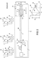
- FIG 1 shows a prior art laser system 10 comprising a laser 1, a beam delivery optical fibre 2, an output optic 3, and an objective lens 4 for focussing laser radiation 5 onto a work piece 6.
- the output optic 3 comprises a lens 7 and an optical isolator 8.
- the lens 7 focuses the laser radiation 5 through the optical isolator 8.
- the laser 1 comprises an amplifying fibre 9 which is pumped by a pump 29.
- a seed laser 11 emits seeding radiation 12 which is amplified by the amplifying fibre 9 to provide a laser signal 13.
- the laser signal 13 is transmitted through the optical fibre 2, and focussed onto the work piece 6 via the output optic 3 and the objective lens 4.
- the lens 7 and the objective lens 4 are selected and located to optimise the focussing of the laser radiation 5 from an output end 14 of the optical fibre 2 to the work piece 6, located a distance 15 from the end 14.
- the optical fibre 2 has a length 86.
- the spectrum 16 of the seeding radiation 12 emitted by the seed laser 11 in the forward direction 26 (away from the laser 1) is defined as the optical power spectral density 17 as a function of wavelength 18.
- the spectrum 16 is shown centred around the signal wavelength 19.
- the spectrum 20 of the laser signal 13 is also shown centred around the signal wavelength 19.
- the laser signal 13 is characterised by a peak power 21. If the peak power 21 is sufficiently high, then the spectrum 23 of the laser signal 22 at the output end 14 of the optical fibre 2 will have a Raman component 24 at the Raman wavelength 25.
- the Raman wavelength 25 is equal to the signal wavelength 19 plus the Raman shift.
- the Raman wavelength 25 is longer than the signal wavelength 19.
- the Raman shift is normally defined in frequency, but for the purposes of this discussion can be considered to be a fixed wavelength shift that is dependent upon both the signal wavelength 19 and the material properties of the optical fibre 2.
- the transmission spectrum 28 through the optical isolator 8 is defined as the transmission 27 as a function of the wavelength 18.
- the optical isolator 8 is preferably optimized for operation at the signal wavelength 19.
- the transmission 27 at the signal wavelength 19 is preferably higher than the transmission at the Raman wavelength 25, which transmission is generally not zero. This is because if the output optic 3 includes the optical isolator 8, as in the system shown in Figure 1 , the optical isolator 8 would be optimized for transmission at the signal wavelength 19.
- Figure 2 shows the operation of the prior art laser system 10 for reflected laser radiation 31 which propagates in the reverse direction 30, that is from the output end 14, along the optical fibre 2, towards the laser 1.
- the reflected laser radiation 31 is shown originating from the work piece 6, it will in general originate from many specular and other sources within the laser system 10.
- the transmission spectrum 32 of the optical isolator 8 has a lower transmission at the signal wavelength 19 in the reverse direction 30 than in the forward direction 26. This difference is defined as the optical isolation 33 of the optical isolator 8 at the signal wavelength 19.
- the optical isolation 77 at the Raman wavelength 25 is in general smaller than the optical isolation 33 at the signal wavelength 19. This has the effect of allowing light at the Raman wavelength 25 to pass through the optical output optic 3 and to be coupled into the optical fibre 2.
- the Raman component 24 of the spectrum 23 at the output end 14 in the forward direction 26 shown in Figure 1 and hence the Raman component 35 of the optical spectrum 34 at the output end 14 in the reverse direction 30 shown in Figure 2 .
- the laser signal 13 is propagating along the optical fibre 2 in the forward direction 26 at the same time as the reflected laser radiation 31 is propagating along the optical fibre 2 in the reverse direction 30, the forward and backward travelling optical radiation 5, 31 will overlap spatially in the optical fibre 2.
- the reflected laser radiation 31 will experience stimulated Raman scattering, which will amplify the Raman component 35.
- the spectrum 36 of the reflected laser radiation 31 will therefore have a larger Raman component 37 at the input end 40 of the fibre 2 than the Raman component 35 at the output end 14 of the fibre 2.
- This Raman component 37 will be further amplified by the amplifying fibre 9 (through at least one of stimulated Raman scattering or conventional linear amplification processes) which will produce an even larger Raman component 39 in the optical spectrum 38 for reflected laser radiation 31 returning to the seed laser 11.
- This amplified stimulated Raman component 39 may be sufficiently high to damage the seed laser 11.
- the stimulated Raman scattering process takes energy from the forward going laser radiation 5 as this is used as the pump for the stimulated Raman scattering process.
- Figure 3 shows a desired pulse shape 41 shown as the variation of optical power 42 with time 44.
- the pulse shape 41 has a pulse width 43. If the peak power 21 of the laser signal 13 is sufficiently high to induce stimulated Raman scattering in the optical fibre 2, then energy is taken out of the forward going laser radiation 5 and the pulse will be distorted as shown in Figure 4 .
- the pulse shape 45 has a distortion 46 caused by forward going laser radiation 5 that has pumped, and therefore lost energy to, the reflected laser radiation 31. Such a distortion 46 is very difficult to model and compensate for owing to the fact that stimulated Raman scattering is a non-linear optical process.
- Figure 5 shows the operation of a laser system 50 which is similar to the laser system 10.
- the optical isolator 8 is located between the laser 1 and the optical fibre 2.
- the output optic 51 is different from the output optic 3 of Figure 1 in that it does not contain an isolator.
- the optical isolator 8 is housed in a housing 52 that includes a lens 7 that collimates light through the optical isolator 8 and another lens 7 that launches light into the optical fibre 2.
- the housing 52 may be located with the chassis (not shown) of the laser 1.
- the transmission spectrum 53 of the output optic 51 preferably includes some attenuation at the Raman wavelength 25 compared to the signal wavelength 19 induced by filters or coatings (such as anti-reflection coatings).
- the optical spectrum 23 will contain a Raman component 24 at the Raman wavelength 25.
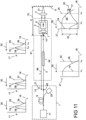
- Figure 6 shows operation of the laser system 50 in the reverse direction 30.
- the optical spectrum 68 of the reflected laser radiation 31 is higher at. the signal wavelength 19 than the optical spectrum 34 shown in Figure 2 as a result of there being no optical isolator in the output optic 51.
- the Raman component 69 will however be a similar level to the Raman component 35, provided that there are no additional filtering components in the output optic 31 than in the output optic 3.
- the Raman component 69 will then be amplified along the fibre 2 by stimulated Raman scattering. If the peak power 21 is sufficiently high, the resulting spectrum 70 at the input end 40 of the optical fibre 2 will have a substantial Raman component 71.
- the optical isolator 8 will attenuate the reflected laser radiation 31 at the signal wavelength 19 more than at the Raman wavelength 25, resulting in the spectrum 64 which has a substantial Raman component 65 at the Raman wavelength 25.
- the spectrum 64 is then amplified in the amplifying fibre 9, resulting in the spectrum 66 at the output of the seed laser 63.
- the spectrum 66 contains a substantial Raman component 67 which may damage the seed laser 11.
- the desired pulse shape 81 at the work piece 6 is shown with reference to Figure 7 .
- the pulse shape 81 has a pulse width 82.
- the effect of stimulated Raman scattering is to remove signal radiation from the forward going laser radiation 5 resulting in the pulse shape 83 having a distortion 84 at the work piece 6.
- Locating the optical isolator 8 adjacent to the laser 1 as shown in Figure 5 can be preferable to the arrangement shown in Figure 1 because it removes an expensive component to a location that is away from reflections from the work piece 6. This has reliability and other maintenance advantages. However, this has not been possible for many high power laser systems because removing the optical isolator 8 from the output optic 3 of Figure 1 has the effect of removing attenuation of the reflected laser radiation 31, permitting more power to propagate in the optical fibre 2.
- Stimulated Raman scattering is a non-linear optical process, whereby the gain is related to the instantaneous peak power.
- the stimulated Raman scattering gain of the apparatus in Figure 5 is twice that of the apparatus shown in Figure 1 and thus the distortion 84 shown in Figure 8 is substantially stronger than the corresponding effect of distortion 46 shown with reference to Figure 4 .
- the Raman component 71 power in the reverse direction 30 entering the optical isolator 8 at the Raman wavelength 25 in Figure 6 will be substantially greater than the corresponding Raman component 37 in Figure 2 , and is therefore more likely to destabilise or damage the laser 1.
- the distortions 46 and 84 are very undesirable, and get worse as the peak power 21 of the laser system 10 increases or if the length 86 of the optical fibre 2 is increased. It is extremely noticeable for single mode or low-moded ytterbium doped fibre laser systems having a length 86 of the optical fibre 2 of around 2 - 5m and peak powers 21 greater than 10kW.
- a low-moded fibre laser can be defined by a beam quality M 2 factor 95 shown with respect to Figure 9 of less than 4, and preferably less than 2.
- the peak power 21 must further be reduced if the length 86 is increased. The effect thus places great design limitations on peak power 21 and fibre length 86.
- the apparatus comprises the laser 1, a beam delivery system 91, and an output port 92, wherein:
- the apparatus is structured in that:
- the apparatus shown with reference to Figure 9 includes the objective lens 4 configured to focus the optical radiation 5 onto the work piece 6, the apparatus being in the form of an apparatus for the industrial processing of materials.
- industrial processing may include cutting, welding, marking, engraving, scribing, cleaning, drilling, cladding, or additive manufacturing.
- the forward going optical radiation 5 provided by the laser 1 is often partially reflected by the work piece 6.
- the forward going optical radiation 5 also includes a component at the Raman wavelength 25, then the effect of the reflected radiation 31 shown with reference to Figure 11 either at the signal wavelength 19 or the Raman wavelength 25 is to remove signal radiation from the forward going laser radiation 5 resulting in the pulse shape having a distortion at the work piece 6 as described previously with reference to Figures 4 and 8 .
- the reflected radiation 31 may also cause damage to the laser 1 or the beam delivery system 91.
- the suppressing means 94 has the effect of reducing the transmission 93 of the optical fibre 2 at the Raman wavelength 25 compared to the signal wavelength 19.
- the forward going Raman component 24 at the output end 14 of the optical fibre 2 in the apparatus of Figure 9 has a lower value compared to the forward going Raman component 24 in the apparatus of Figure 1 .
- the spectrum 34 of the reflected laser radiation 31, shown with reference to Figure 11 has a smaller Raman component 35 at the Raman wavelength 25 than the spectrum 34 shown with reference to Figure 2 .
- the suppressing means 94 will further filter the Raman component 35 of the reflected optical radiation 31 as it propagates back towards the laser 1, leading to reduced Raman components 37 and 39 of the spectra 36 and 38 compared to the system shown in Figure 2 .
- Figure 12 shows a filter 135 that can be included in the beam delivery system 121 to filter the Raman component 24.
- the filter 135 can be a dielectric filter that attenuates optical radiation.
- the filter 135 can also be included in the beam delivery system 91 of Figure 9 .
- the optical isolator 8 can be positioned between the laser 1 and the optical fibre 2 as shown in Figures 12 and 13 .
- the beam delivery system 91 of Figure 9 has been replaced by the beam delivery system 121.
- This is similar to the system shown in Figures 5 and 6 , save that the optical fibre 2 comprises the suppressing means 94.
- the effect of the stimulated Raman scattering suppressing means 94 is to reduce the Raman component 24 of the spectrum 23 at the output end 14 for both forward going laser radiation 5 and the reflected laser radiation 31.
- the Raman component 69 shown in Figure 13 is further suppressed as it propagates along the optical fibre 2 towards the optical isolator 8.
- the Raman components 71, 65 and 67 of the apparatus shown in Figures 12 and 13 are consequently smaller than the equivalent Raman components of the apparatus shown in Figures 5 and 6 .
- the laser 1 may emit laser radiation 13 that is polarized.
- the optical isolator 8 may be a polarization dependent isolator.
- the laser 1 may emit laser radiation 13 that is randomly polarized.
- the optical isolator 8 may be a polarization independent isolator.
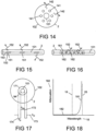
- the suppressing means 94 may comprise high refractive index features 141 adjacent to the core 101, as shown in Figure 14 .
- high refractive index features it is meant that the refractive index of these features 141 is higher than a refractive index of the cladding 102.
- the refractive index is higher than a refractive index of the core 101.
- the high refractive index features 141 are designed to couple optical radiation propagating at the Raman wavelength 25 from the core 101 into leaky modes 142.
- the coupling at the Raman wavelength 25 is much stronger than the coupling at the signal wavelength 19.
- the suppressing means 94 can be used to remove unwanted optical radiation propagating in both the fundamental mode as well as higher order modes.
- the suppressing means 94 may comprise one or more blazed gratings 151 designed to couple optical radiation 152 at the Raman wavelength 25 out of the core 101.
- Blazed gratings have a plurality of grating lines 153 at a non-perpendicular angle to the axis of the fibre 2 as shown in Figure 15 .
- the suppressing means 94 may comprise one or more long period gratings 161, as shown in Figure 16 , designed to couple optical radiation 152 at the Raman wavelength 25 out of the core 101.
- Long period gratings comprise a plurality of refractive index modifying features 167 along the core 101 of the optical fibre 2.
- the coupling can be between core guided modes (not shown) and leaky modes (not shown), or between core guided modes and guided modes of another waveguide (not shown) with the optical fibre 2.
- the suppressing means 94 may comprise a depressed refractive index cladding 171 adjacent to, or surrounding the core 101, as shown in Figure 17 .
- the core 101 has a refractive index 172 that is greater than a refractive index 173 of the cladding 102.
- the refractive index 174 of the depressed refractive index cladding 171 is less than the refractive index 173 of the cladding 102.
- Figure 18 shows the optical attenuation 182 as a function of wavelength 18.
- the fibre 2 can be designed to have a sharp bend edge 181 such the attenuation 182 at the Raman wavelength 25 is substantially higher than the attenuation 182 at the signal wavelength 19.
- the stability of the bend edge 182 can be enhanced by arranging for the optical fibre 2 to be spiralled when cabled, for example, by wrapping around a central member.
- the suppressing means 94 is distributed along the optical fibre 2, such as in the arrangements shown in Figures 14 and 17 .
- the arrangements shown in Figures 14 to 17 are suitable for suppressing stimulated Raman scattering in the fundamental mode of the optical fibre 2.
- the arrangement shown in Figure 14 can also be configured to. suppress the stimulated Raman scattering in higher order modes of the optical fibre 2, which is advantageous for higher power laser systems, and especially advantageous for multiple transverse mode pulsed fibre laser systems.
- the suppressing means 94 enables the peak power 21 of the laser radiation 5 to be substantially increased without causing damage or instability to the laser 1. Alternatively, or additionally, the suppressing means 94 enables the length 86 of the optical fibre 2 to be increased.
- the laser 1 can be a pulsed laser and the peak power 21 may be at least 1,000 times its average power.
- the peak power 21 may be 10 to 10,000 times its average power.
- the laser 1 can be nanosecond, picosecond or femtosecond laser, and the peak power 21 may be 1,000 to 1,000,000 times its average power.
- a eff g R . P p where g R is the Raman gain coefficient of the optical fibre 2.
- the length 86 can be at least 1.5 times the critical length L c .
- the length 86 is at least 2 times the critical length L c . More preferably, the length 86 is at least five or ten times the critical length L c .
- the laser 1 described with reference to Figures 1 , 2 , 5 , 6 , 9 and 11-13 and in the discussion relating to the critical length L c is a master oscillator power amplifier.
- a master oscillator power amplifier is preferred because the pulse parameters of pulses emitted by the laser 1, such as pulse shape, peak power, and pulse repetition rate, can be controlled by controlling the drive signals to the master oscillator and to the power amplifier.
- the laser 1 may also be, for example, a Q-switched laser, a mode locked laser, or a continuous wave laser. If the laser is a continuous wave laser, then the peak power 21 is the maximum laser power that can be emitted by the laser 1.
- the laser 1 may also be, for example, a fibre laser, a solid state laser such as a rod laser or a disc laser, or a gas laser. Additional filtering at the Raman wavelength 25 can be incorporated into the apparatus described with reference to Figures 9 and 12 .
- Figure 9 shows the output power of a pulse 96 of the optical radiation 5 as a function of distance 98. If the spatial pulse length 97 in vacuum is greater than 2d (that is twice the distance 15 from the end 14 of the optical fibre 2 to the work piece 6) then the reflected optical radiation 31 will at least partially overlap the forward going optical radiation 5 in the optical fibre 2. This overlap can result in stimulated Raman scattering.
- the suppressing means 94 permits the reflected optical radiation 31 to overlap the forward going optical radiation 5 without the distortion or destabilising effects caused by stimulated Raman scattering at higher peak powers 21 or longer lengths 86 than would otherwise be the case.
- the suppressing means 94 helps to suppress the resulting stimulated Raman scattering that can occur with combinations of peak power 21 and length 86.
- the pulse width may be at least 100ps.
- the pulse width may be at least 1ns.
- the spatial length (not shown) of the optical pulse 96 within the optical fibre 2 is reduced by the refractive index of the optical fibre 2.
- the spatial length (not shown) is approximately equal to the spatial length 97 divided by 1.5.
- the laser 1 may be configured to emit a pulse that has a spatial length (not shown) of between two times and ten times the length L 86 of the optical fibre 2.
- the spatial length (not shown) may be less than five times the length 86 of the optical fibre 2.
- the spatial length may be less than pulse having two times the length 86 of the optical fibre 2.
- a pulse having a spatial length (not shown) of at least twice the length 86 of the optical fibre 2 will overlap in the optical fibre 2 completely at least once during a reflection from the fibre end 14.
- the laser 1 may emit a pulse that has a spatial pulse length (not shown) less than 10L, preferably less than 5L, and more preferably less than 2L.
- Incorporation of the suppressing means 94 permits the reflected optical radiation 31 to overlap the forward going optical radiation 5 without the distortion or destabilising effects caused by stimulated Raman scattering at higher peak powers 21 or longer lengths 86 than would otherwise be the case. It is therefore possible to increase one or both of the peak power 21 and the length 86 in the apparatus described with reference to Figures 9 and 12 without the distortion or destabilising effects caused by stimulated Raman scattering.
- the laser 1 may be able to emit a pulse 21 having a pulse width less than or equal to 2 ⁇ s.
- the pulse width may be less than or equal to 500ns.
- the pulse width may be less than or equal to 100ns.
- the pulse width may be less than or equal to 25ns.
- the laser may be configured to emit a plurality of the pulses, and the spatial separation (not shown) in the optical fibre 2 between adjacent pulses may be less than or equal to twice the length 86 of the optical fibre 2. Incorporation of the suppressing means 94 permits the reflected optical radiation 31 to overlap the forward going optical radiation 5 without the distortion or destabilising effects caused by stimulated Raman scattering at higher peak powers 21 or longer lengths 86 than would otherwise be the case. It is therefore possible to increase one or both of the peak power 21 and the length 86 in the apparatus described with reference to Figures 9 and 12 without the distortion or destabilising effects caused by stimulated Raman scattering.
- the laser 1 may have a pulse repetition frequency of at least 1MHz, preferably at least 5MHz, and more preferably at least 20MHz.
- the laser 1 is preferably a fibre laser.
- the fibre laser is preferably configured as a master oscillator power amplifier.
- the laser 1 may be a multimode laser or a single mode laser.
- the laser 1 preferably emits optical radiation in the fundamental mode.
- the laser 1 is preferably a pulsed fibre laser comprising a rare earth doped fibre in which energy is stored between emitted pulses. More preferably, the laser 1 is a ytterbium-doped fibre laser defined by a beam quality M 2 factor 95 less than 2 and a peak power greater 21 than 10kW. Other ranges of beam quality M 2 factor 95 are also useful as described with reference to Figure 14 .
- the laser is preferably configured as a master oscillator power amplifier.
- Such a laser is an important component of material processing systems, and the present invention is particularly advantageous because it prevents back reflected optical radiation from reaching the rare earth doped fibre in a manner that would destabilized the laser or cause damage to the laser. If the laser is destabilized then the material processing system would be adversely affected.
Landscapes
- Physics & Mathematics (AREA)
- Electromagnetism (AREA)
- Engineering & Computer Science (AREA)
- Optics & Photonics (AREA)
- Plasma & Fusion (AREA)
- Mechanical Engineering (AREA)
- Lasers (AREA)
- Laser Beam Processing (AREA)
- Optical Couplings Of Light Guides (AREA)
Claims (16)
- Einrichtung für die industrielle Bearbeitung von Materialien, wobei die Einrichtung einen Laser (1), ein Strahlabgabesystem (91), eine Ausgabeöffnung (92) und eine Objektivlinse (4) umfasst, wobei:das Strahlabgabesystem einen optischen Isolator (8) und eine optische Abgabefaser (2) umfasst,der Laser dazu konfiguriert ist, gepulste Laserstrahlung (13) bei einer Signalwellenlänge (19) mit einem Impuls mit einer Spitzenleistung Pp (21) zu emittieren,wobei das Strahlabgabesystem dazu konfiguriert ist, die Laserstrahlung von dem Laser in die Ausgabeöffnung zu koppeln;die Objektivlinse dazu konfiguriert ist, die Laserstrahlung auf ein Werkstück (6) zu fokussieren;sich ein Ausgabeende der optischen Faser in einem Abstand d von dem Werkstück befindet;die optische Faser einen optischen Wellenleiter (100) umfasst, der durch einen Kern (101), einen Mantel (102), eine Modenfeldfläche Aeff (104) bei der Signalwellenlänge, eine Länge L und, da die Abgabefaser dazu konfiguriert ist, das Signal zu übertragen, einen Raman-Verstärkungskoeffizienten gR und eine Raman-Wellenlänge (25) definiert ist,die Raman-Wellenlänge größer ist als die Signalwellenlänge,das Strahlabgabesystem dazu konfiguriert ist, die Laserstrahlung (13) bei der Signalwellenlänge derart abzuschwächen, dass die Leistung der von dem Laser emittierten Laserstrahlung größer ist als die Leistung der Laserstrahlung an der Ausgabeöffnung;die Einrichtung keine Pumpe zum Pumpen der Laserstrahlung bei der Signalwellenlänge beinhaltet, wenn sich die Laserstrahlung entlang der optischen Faser ausbreitet;der optische Isolator eine größere optische Rückwärtsisolation (33) und eine größere Vorwärtsübertragung (28) bei der Signalwellenlänge im Vergleich zu der Raman-Wellenlänge aufweist; wobei:die Länge L der optischen Faser größer ist als eine kritische Länge Lc, die gleich dem Quotienten aus dem 16-fachen der Modenfeldfläche Aeff und dem Produkt aus dem Raman-Verstärkungskoeffizienten gR der optischen Faser und der Spitzenleistung Pp ist, d. h.
 der Laser dazu konfiguriert ist, einen Impuls (96) zu emittieren, der die Projektionslinse mit einer räumlichen Länge (97) im Vakuum von mehr als 2d verlässt; unddie optische Faser ein Unterdrückungsmittel (94) für die Unterdrückung der stimulierten Raman-Streuung umfasst:
wobei das Unterdrückungsmittel dazu konfiguriert ist, der von dem Werkstück reflektierten optischen Strahlung (31) zu erlauben, die vorwärts gehende optische Strahlung (5) ohne die durch stimulierte Raman-Streuung verursachten Verzerrungs- oder Destabilisierungseffekte zu überlappen. - Einrichtung nach Anspruch 1, wobei das Unterdrückungsmittel über die Länge der optischen Faser verteilt ist.
- Einrichtung nach Anspruch 1 oder 2, wobei das Unterdrückungsmittel Merkmale (141) mit hohem Brechungsindex umfasst, die den Kern umgeben und dazu konfiguriert sind, die Kopplung von Licht in Leckmoden bei der Raman-Wellenlänge im Vergleich zu der Kopplung von Licht in Leckmoden bei der Signalwellenlänge zu erhöhen.
- Einrichtung nach Anspruch 3, wobei das Unterdrückungsmittel dazu konfiguriert ist, stimulierte Raman-Streuung in Moden höherer Ordnung der optischen Faser zu unterdrücken.
- Einrichtung nach Anspruch 1 oder 2, wobei das Unterdrückungsmittel wenigstens ein Blaze-Gitter (151) umfasst.
- Einrichtung nach einem der vorhergehenden Ansprüche, wobei das Unterdrückungsmittel wenigstens ein langperiodisches Gitter (161) umfasst.
- Einrichtung nach einem der vorhergehenden Ansprüche, wobei das Unterdrückungsmittel einen Bereich (171) mit abgesenktem Brechungsindex umfasst, der den Kern umgibt.
- Einrichtung nach einem der vorangehenden Ansprüche, wobei sich der optische Isolator zwischen dem Laser und der optischen Faser befindet.
- Einrichtung nach einem der Ansprüche 1 bis 7, wobei sich die optische Faser zwischen dem Laser und dem optischen Isolator befindet.
- Einrichtung nach einem der vorhergehenden Ansprüche, wobei der Laser dazu konfiguriert ist, den Impuls (96) zu emittieren, der eine räumliche Länge in der optischen Faser zwischen dem Zweifachen und dem Zehnfachen der Länge der optischen Faser aufweist.
- Einrichtung nach Anspruch 10, wobei die räumliche Länge weniger als das Fünffache der Länge der optischen Faser beträgt.
- Einrichtung nach Anspruch 11, wobei die räumliche Länge weniger als das Zweifache der Länge der optischen Faser beträgt.
- Einrichtung nach einem der vorhergehenden Ansprüche, wobei der Laser dazu konfiguriert ist, eine Mehrzahl von Impulsen zu emittieren, und der räumliche Abstand in der optischen Faser zwischen benachbarten Impulsen weniger als oder gleich dem Zweifachen der Länge der optischen Faser beträgt.
- Einrichtung nach einem der vorhergehenden Ansprüche, wobei der Laser ein Ytterbium-dotierter Faserlaser ist, der durch einen Strahlqualitätsfaktor M2 kleiner als 2 und eine Spitzenleistung Pp größer als 10 kW definiert ist.
- Einrichtung nach einem der vorangehenden Ansprüche, wobei der Laser als ein Master-Oszillator-Leistungsverstärker konfiguriert ist.
- Verfahren zum industriellen Bearbeiten von Materialien, wobei das Verfahren das Bereitstellen eines Lasers, eines Strahlabgabesystems, einer Ausgabeöffnung und einer Objektivlinse umfasst, wobei:das Strahlabgabesystem einen optischen Isolator und eine optische Faser umfasst,der Laser gepulste Laserstrahlung bei einer Signalwellenlänge mit einem Impuls mit einer Spitzenleistung Pp emittiert,die Kopplung der Laserstrahlung von dem Laser in die Ausgabeöffnung über das Strahlabgabesystem erfolgt;die Laserstrahlung auf ein Werkstück fokussiert wird, das sich in einem Abstand d von einem Ausgabeende der optischen Faser befindet;die optische Faser einen optischen Wellenleiter umfasst, der durch einen Kern, einen Mantel, eine Modenfeldfläche Aeff bei der Signalwellenlänge, eine Länge L und, aufgrund des durch die Abgabefaser übertragenen Signals, einen Raman-Verstärkungskoeffizienten gR und eine Raman-Wellenlänge definiert ist,die Raman-Wellenlänge größer ist als die Signalwellenlänge,das Strahlabgabesystem die Laserstrahlung bei der Signalwellenlänge derart abschwächt, dass die Leistung der von dem Laser emittierten Laserstrahlung größer ist als die Leistung der Laserstrahlung an der Ausgabeöffnung;die Einrichtung keine Pumpe zum Pumpen der Laserstrahlung bei der Signalwellenlänge beinhaltet, wenn sich die Laserstrahlung entlang der optischen Faser ausbreitet;der optische Isolator eine größere optische Rückwärtsisolation und eine größere Vorwärtsübertragung bei der Signalwellenlänge im Vergleich zu der Raman-Wellenlänge aufweist; und:die Länge L der optischen Faser größer ist als eine kritische Länge Lc, die gleich dem Quotienten aus dem 16-fachen des Modenfeldes Aeff und dem Produkt aus dem Raman-Verstärkungskoeffizienten gR der optischen Faser und der Spitzenleistung Pp ist, d. h.
 Veranlassen, dass der Laser einen Impuls emittiert, der die Objektivlinse mit einer räumlichen Länge im Vakuum von mehr als 2d verlässt; unddie optische Faser ein Unterdrückungsmittel für die Unterdrückung der stimulierten Raman-Streuung umfasst,wobei der Einbau des Unterdrückungsmittels es erlaubt, dass optische Strahlung, die von dem Werkstück reflektiert wird, die vorwärts gehende optische Strahlung ohne die durch stimulierte Raman-Streuung verursachten Verzerrungs- oder Destabilisierungseffekte überlappt.
Applications Claiming Priority (2)
| Application Number | Priority Date | Filing Date | Title |
|---|---|---|---|
| GBGB1601815.2A GB201601815D0 (en) | 2016-01-29 | 2016-01-29 | Apparatus and method for optical isolation |
| PCT/GB2017/000012 WO2017129939A2 (en) | 2016-01-29 | 2017-01-27 | Apparatus and method for optical isolation |
Publications (2)
| Publication Number | Publication Date |
|---|---|
| EP3408901A2 EP3408901A2 (de) | 2018-12-05 |
| EP3408901B1 true EP3408901B1 (de) | 2023-06-07 |
Family
ID=55590518
Family Applications (1)
| Application Number | Title | Priority Date | Filing Date |
|---|---|---|---|
| EP17704521.8A Active EP3408901B1 (de) | 2016-01-29 | 2017-01-27 | Vorrichtung und verfahren zur optischen isolierung |
Country Status (5)
| Country | Link |
|---|---|
| US (1) | US10931075B2 (de) |
| EP (1) | EP3408901B1 (de) |
| CN (1) | CN108701952B (de) |
| GB (1) | GB201601815D0 (de) |
| WO (1) | WO2017129939A2 (de) |
Families Citing this family (8)
| Publication number | Priority date | Publication date | Assignee | Title |
|---|---|---|---|---|
| GB201701506D0 (en) * | 2017-01-30 | 2017-03-15 | Spi Lasers Uk Ltd | Apparatus and method for optical isolation |
| JP6523511B1 (ja) | 2018-03-30 | 2019-06-05 | 株式会社フジクラ | ファイバレーザ装置、ファイバレーザ装置の製造方法、及び、設定方法 |
| WO2020139705A1 (en) * | 2018-12-28 | 2020-07-02 | Nlight, Inc. | Optical fiber devices for directing stimulated raman scattering (srs) light out of a fiber |
| US11731198B2 (en) | 2019-08-20 | 2023-08-22 | Rosemount Aerospace Inc. | Additive manufacturing system including an optical isolator |
| GB201913629D0 (en) * | 2019-09-20 | 2019-11-06 | Alltec Angewandte Laserlicht Tech Gmbh | Electromagnetic radiation system |
| EP3809175B1 (de) * | 2019-10-18 | 2022-03-02 | Centre National De La Recherche Scientifique -Cnrs- | Verfahren zum verzögern eines optischen signals |
| JP6859556B1 (ja) * | 2020-03-13 | 2021-04-14 | 合同会社酸素レーザー研究所 | 癌治療装置 |
| CN114447744B (zh) * | 2022-01-28 | 2025-05-20 | 江苏师范大学 | 一种产生高相位相干度电磁波信号的激光器及方法 |
Citations (1)
| Publication number | Priority date | Publication date | Assignee | Title |
|---|---|---|---|---|
| US20090046746A1 (en) * | 2007-07-06 | 2009-02-19 | Deep Photonics Corporation | Pulsed fiber laser |
Family Cites Families (13)
| Publication number | Priority date | Publication date | Assignee | Title |
|---|---|---|---|---|
| DE69809413T2 (de) * | 1997-05-27 | 2003-05-08 | Sdl, Inc. | Lasermarkierungssystem und energiesteuerungsverfahren |
| US6778320B1 (en) * | 2000-11-20 | 2004-08-17 | Avanex Corporation | Composite optical amplifier |
| WO2002093697A2 (en) * | 2001-05-15 | 2002-11-21 | Optical Power Systems Incorporated | Fiber laser having a suppressor |
| US20030021302A1 (en) * | 2001-07-18 | 2003-01-30 | Grudinin Anatoly Borisovich | Raman cascade light sources |
| US7590155B2 (en) * | 2004-08-05 | 2009-09-15 | Jian Liu | Hybrid high power laser to achieve high repetition rate and high pulse energy |
| JP4998357B2 (ja) * | 2007-04-13 | 2012-08-15 | 住友電気工業株式会社 | フォトニックバンドギャップ光ファイバ、光伝送システム及びそのシステムにおける誘導ラマン散乱抑制方法 |
| JP2009032910A (ja) * | 2007-07-27 | 2009-02-12 | Hitachi Cable Ltd | 光ファイバレーザ用光ファイバ及びその製造方法、並びに光ファイバレーザ |
| GB0802562D0 (en) * | 2008-02-12 | 2008-03-19 | Fianium Ltd | A source of femtosecond laser pulses |
| JP2011114061A (ja) * | 2009-11-25 | 2011-06-09 | Fujikura Ltd | レーザ発振器、及び、モードフィルタ |
| GB201108470D0 (en) * | 2011-05-19 | 2011-07-06 | Spi Lasers Uk Ltd | Apparatus and method for optical isolation |
| JP5975026B2 (ja) * | 2011-06-03 | 2016-08-23 | 住友電気工業株式会社 | 光源装置および加工方法 |
| US9293888B2 (en) * | 2013-10-30 | 2016-03-22 | Raytheon Company | Method and apparatus for high-power raman beam-combining in a multimode optical fiber |
| CN103878486B (zh) * | 2014-03-21 | 2016-03-02 | 中国人民解放军总装备部军械技术研究所 | 便携式激光除锈机 |
-
2016
- 2016-01-29 GB GBGB1601815.2A patent/GB201601815D0/en not_active Ceased
-
2017
- 2017-01-27 EP EP17704521.8A patent/EP3408901B1/de active Active
- 2017-01-27 CN CN201780008822.6A patent/CN108701952B/zh active Active
- 2017-01-27 WO PCT/GB2017/000012 patent/WO2017129939A2/en not_active Ceased
- 2017-01-27 US US16/070,128 patent/US10931075B2/en active Active
Patent Citations (1)
| Publication number | Priority date | Publication date | Assignee | Title |
|---|---|---|---|---|
| US20090046746A1 (en) * | 2007-07-06 | 2009-02-19 | Deep Photonics Corporation | Pulsed fiber laser |
Also Published As
| Publication number | Publication date |
|---|---|
| WO2017129939A3 (en) | 2017-08-31 |
| US10931075B2 (en) | 2021-02-23 |
| EP3408901A2 (de) | 2018-12-05 |
| CN108701952A (zh) | 2018-10-23 |
| CN108701952B (zh) | 2020-05-29 |
| US20190027888A1 (en) | 2019-01-24 |
| GB201601815D0 (en) | 2016-03-16 |
| WO2017129939A2 (en) | 2017-08-03 |
Similar Documents
| Publication | Publication Date | Title |
|---|---|---|
| EP3408901B1 (de) | Vorrichtung und verfahren zur optischen isolierung | |
| JP5467864B2 (ja) | 光放射を提供する装置 | |
| CN101946377B (zh) | 光纤激光器 | |
| JP5185929B2 (ja) | ファイバレーザ | |
| JP5260146B2 (ja) | 光源装置 | |
| US20210194199A1 (en) | Fiber laser system with mechanism for inducing parasitic lights losses | |
| JP2012243789A (ja) | ファイバレーザ加工装置及びレーザ加工方法 | |
| CN211265956U (zh) | 用于提供光学辐射的装置 | |
| KR101780866B1 (ko) | 파이버 레이저 장치 | |
| US10985519B2 (en) | Active LMA optical fiber and laser system using the same | |
| CN105470802B (zh) | 全光纤声光调q激光器及其输出方法 | |
| EP4666353A1 (de) | Optische faser und faseroptische vorrichtung | |
| EP4085301A1 (de) | Verfahren zur optischen isolation | |
| JPWO2012165163A1 (ja) | レーザ装置及びレーザ加工方法 | |
| Melo et al. | Stimulated Raman scattering mitigation through amplified spontaneous emission simultaneous seeding on high power double-clad fiber pulse amplifiers |
Legal Events
| Date | Code | Title | Description |
|---|---|---|---|
| STAA | Information on the status of an ep patent application or granted ep patent |
Free format text: STATUS: UNKNOWN |
|
| STAA | Information on the status of an ep patent application or granted ep patent |
Free format text: STATUS: THE INTERNATIONAL PUBLICATION HAS BEEN MADE |
|
| PUAI | Public reference made under article 153(3) epc to a published international application that has entered the european phase |
Free format text: ORIGINAL CODE: 0009012 |
|
| STAA | Information on the status of an ep patent application or granted ep patent |
Free format text: STATUS: REQUEST FOR EXAMINATION WAS MADE |
|
| 17P | Request for examination filed |
Effective date: 20180718 |
|
| AK | Designated contracting states |
Kind code of ref document: A2 Designated state(s): AL AT BE BG CH CY CZ DE DK EE ES FI FR GB GR HR HU IE IS IT LI LT LU LV MC MK MT NL NO PL PT RO RS SE SI SK SM TR |
|
| AX | Request for extension of the european patent |
Extension state: BA ME |
|
| STAA | Information on the status of an ep patent application or granted ep patent |
Free format text: STATUS: EXAMINATION IS IN PROGRESS |
|
| DAV | Request for validation of the european patent (deleted) | ||
| DAX | Request for extension of the european patent (deleted) | ||
| 17Q | First examination report despatched |
Effective date: 20190509 |
|
| 17Q | First examination report despatched |
Effective date: 20190617 |
|
| GRAP | Despatch of communication of intention to grant a patent |
Free format text: ORIGINAL CODE: EPIDOSNIGR1 |
|
| STAA | Information on the status of an ep patent application or granted ep patent |
Free format text: STATUS: GRANT OF PATENT IS INTENDED |
|
| INTG | Intention to grant announced |
Effective date: 20201119 |
|
| GRAJ | Information related to disapproval of communication of intention to grant by the applicant or resumption of examination proceedings by the epo deleted |
Free format text: ORIGINAL CODE: EPIDOSDIGR1 |
|
| STAA | Information on the status of an ep patent application or granted ep patent |
Free format text: STATUS: EXAMINATION IS IN PROGRESS |
|
| INTC | Intention to grant announced (deleted) | ||
| GRAP | Despatch of communication of intention to grant a patent |
Free format text: ORIGINAL CODE: EPIDOSNIGR1 |
|
| STAA | Information on the status of an ep patent application or granted ep patent |
Free format text: STATUS: GRANT OF PATENT IS INTENDED |
|
| INTG | Intention to grant announced |
Effective date: 20210422 |
|
| GRAJ | Information related to disapproval of communication of intention to grant by the applicant or resumption of examination proceedings by the epo deleted |
Free format text: ORIGINAL CODE: EPIDOSDIGR1 |
|
| STAA | Information on the status of an ep patent application or granted ep patent |
Free format text: STATUS: EXAMINATION IS IN PROGRESS |
|
| INTC | Intention to grant announced (deleted) | ||
| RAP3 | Party data changed (applicant data changed or rights of an application transferred) |
Owner name: TRUMPF LASER UK LIMITED |
|
| GRAP | Despatch of communication of intention to grant a patent |
Free format text: ORIGINAL CODE: EPIDOSNIGR1 |
|
| STAA | Information on the status of an ep patent application or granted ep patent |
Free format text: STATUS: GRANT OF PATENT IS INTENDED |
|
| INTG | Intention to grant announced |
Effective date: 20221007 |
|
| GRAS | Grant fee paid |
Free format text: ORIGINAL CODE: EPIDOSNIGR3 |
|
| GRAA | (expected) grant |
Free format text: ORIGINAL CODE: 0009210 |
|
| STAA | Information on the status of an ep patent application or granted ep patent |
Free format text: STATUS: THE PATENT HAS BEEN GRANTED |
|
| AK | Designated contracting states |
Kind code of ref document: B1 Designated state(s): AL AT BE BG CH CY CZ DE DK EE ES FI FR GB GR HR HU IE IS IT LI LT LU LV MC MK MT NL NO PL PT RO RS SE SI SK SM TR |
|
| REG | Reference to a national code |
Ref country code: GB Ref legal event code: FG4D |
|
| REG | Reference to a national code |
Ref country code: CH Ref legal event code: EP Ref country code: AT Ref legal event code: REF Ref document number: 1577740 Country of ref document: AT Kind code of ref document: T Effective date: 20230615 |
|
| REG | Reference to a national code |
Ref country code: DE Ref legal event code: R096 Ref document number: 602017069447 Country of ref document: DE |
|
| P01 | Opt-out of the competence of the unified patent court (upc) registered |
Effective date: 20230529 |
|
| REG | Reference to a national code |
Ref country code: LT Ref legal event code: MG9D |
|
| REG | Reference to a national code |
Ref country code: NL Ref legal event code: MP Effective date: 20230607 |
|
| PG25 | Lapsed in a contracting state [announced via postgrant information from national office to epo] |
Ref country code: SE Free format text: LAPSE BECAUSE OF FAILURE TO SUBMIT A TRANSLATION OF THE DESCRIPTION OR TO PAY THE FEE WITHIN THE PRESCRIBED TIME-LIMIT Effective date: 20230607 Ref country code: NO Free format text: LAPSE BECAUSE OF FAILURE TO SUBMIT A TRANSLATION OF THE DESCRIPTION OR TO PAY THE FEE WITHIN THE PRESCRIBED TIME-LIMIT Effective date: 20230907 Ref country code: ES Free format text: LAPSE BECAUSE OF FAILURE TO SUBMIT A TRANSLATION OF THE DESCRIPTION OR TO PAY THE FEE WITHIN THE PRESCRIBED TIME-LIMIT Effective date: 20230607 |
|
| REG | Reference to a national code |
Ref country code: AT Ref legal event code: MK05 Ref document number: 1577740 Country of ref document: AT Kind code of ref document: T Effective date: 20230607 |
|
| PG25 | Lapsed in a contracting state [announced via postgrant information from national office to epo] |
Ref country code: RS Free format text: LAPSE BECAUSE OF FAILURE TO SUBMIT A TRANSLATION OF THE DESCRIPTION OR TO PAY THE FEE WITHIN THE PRESCRIBED TIME-LIMIT Effective date: 20230607 Ref country code: NL Free format text: LAPSE BECAUSE OF FAILURE TO SUBMIT A TRANSLATION OF THE DESCRIPTION OR TO PAY THE FEE WITHIN THE PRESCRIBED TIME-LIMIT Effective date: 20230607 Ref country code: LV Free format text: LAPSE BECAUSE OF FAILURE TO SUBMIT A TRANSLATION OF THE DESCRIPTION OR TO PAY THE FEE WITHIN THE PRESCRIBED TIME-LIMIT Effective date: 20230607 Ref country code: LT Free format text: LAPSE BECAUSE OF FAILURE TO SUBMIT A TRANSLATION OF THE DESCRIPTION OR TO PAY THE FEE WITHIN THE PRESCRIBED TIME-LIMIT Effective date: 20230607 Ref country code: HR Free format text: LAPSE BECAUSE OF FAILURE TO SUBMIT A TRANSLATION OF THE DESCRIPTION OR TO PAY THE FEE WITHIN THE PRESCRIBED TIME-LIMIT Effective date: 20230607 Ref country code: GR Free format text: LAPSE BECAUSE OF FAILURE TO SUBMIT A TRANSLATION OF THE DESCRIPTION OR TO PAY THE FEE WITHIN THE PRESCRIBED TIME-LIMIT Effective date: 20230908 |
|
| PG25 | Lapsed in a contracting state [announced via postgrant information from national office to epo] |
Ref country code: FI Free format text: LAPSE BECAUSE OF FAILURE TO SUBMIT A TRANSLATION OF THE DESCRIPTION OR TO PAY THE FEE WITHIN THE PRESCRIBED TIME-LIMIT Effective date: 20230607 |
|
| PG25 | Lapsed in a contracting state [announced via postgrant information from national office to epo] |
Ref country code: SK Free format text: LAPSE BECAUSE OF FAILURE TO SUBMIT A TRANSLATION OF THE DESCRIPTION OR TO PAY THE FEE WITHIN THE PRESCRIBED TIME-LIMIT Effective date: 20230607 |
|
| PG25 | Lapsed in a contracting state [announced via postgrant information from national office to epo] |
Ref country code: IS Free format text: LAPSE BECAUSE OF FAILURE TO SUBMIT A TRANSLATION OF THE DESCRIPTION OR TO PAY THE FEE WITHIN THE PRESCRIBED TIME-LIMIT Effective date: 20231007 |
|
| PG25 | Lapsed in a contracting state [announced via postgrant information from national office to epo] |
Ref country code: SM Free format text: LAPSE BECAUSE OF FAILURE TO SUBMIT A TRANSLATION OF THE DESCRIPTION OR TO PAY THE FEE WITHIN THE PRESCRIBED TIME-LIMIT Effective date: 20230607 Ref country code: SK Free format text: LAPSE BECAUSE OF FAILURE TO SUBMIT A TRANSLATION OF THE DESCRIPTION OR TO PAY THE FEE WITHIN THE PRESCRIBED TIME-LIMIT Effective date: 20230607 Ref country code: RO Free format text: LAPSE BECAUSE OF FAILURE TO SUBMIT A TRANSLATION OF THE DESCRIPTION OR TO PAY THE FEE WITHIN THE PRESCRIBED TIME-LIMIT Effective date: 20230607 Ref country code: PT Free format text: LAPSE BECAUSE OF FAILURE TO SUBMIT A TRANSLATION OF THE DESCRIPTION OR TO PAY THE FEE WITHIN THE PRESCRIBED TIME-LIMIT Effective date: 20231009 Ref country code: IS Free format text: LAPSE BECAUSE OF FAILURE TO SUBMIT A TRANSLATION OF THE DESCRIPTION OR TO PAY THE FEE WITHIN THE PRESCRIBED TIME-LIMIT Effective date: 20231007 Ref country code: EE Free format text: LAPSE BECAUSE OF FAILURE TO SUBMIT A TRANSLATION OF THE DESCRIPTION OR TO PAY THE FEE WITHIN THE PRESCRIBED TIME-LIMIT Effective date: 20230607 Ref country code: CZ Free format text: LAPSE BECAUSE OF FAILURE TO SUBMIT A TRANSLATION OF THE DESCRIPTION OR TO PAY THE FEE WITHIN THE PRESCRIBED TIME-LIMIT Effective date: 20230607 Ref country code: AT Free format text: LAPSE BECAUSE OF FAILURE TO SUBMIT A TRANSLATION OF THE DESCRIPTION OR TO PAY THE FEE WITHIN THE PRESCRIBED TIME-LIMIT Effective date: 20230607 |
|
| PG25 | Lapsed in a contracting state [announced via postgrant information from national office to epo] |
Ref country code: PL Free format text: LAPSE BECAUSE OF FAILURE TO SUBMIT A TRANSLATION OF THE DESCRIPTION OR TO PAY THE FEE WITHIN THE PRESCRIBED TIME-LIMIT Effective date: 20230607 |
|
| REG | Reference to a national code |
Ref country code: DE Ref legal event code: R097 Ref document number: 602017069447 Country of ref document: DE |
|
| PLBE | No opposition filed within time limit |
Free format text: ORIGINAL CODE: 0009261 |
|
| STAA | Information on the status of an ep patent application or granted ep patent |
Free format text: STATUS: NO OPPOSITION FILED WITHIN TIME LIMIT |
|
| PG25 | Lapsed in a contracting state [announced via postgrant information from national office to epo] |
Ref country code: DK Free format text: LAPSE BECAUSE OF FAILURE TO SUBMIT A TRANSLATION OF THE DESCRIPTION OR TO PAY THE FEE WITHIN THE PRESCRIBED TIME-LIMIT Effective date: 20230607 |
|
| PG25 | Lapsed in a contracting state [announced via postgrant information from national office to epo] |
Ref country code: SI Free format text: LAPSE BECAUSE OF FAILURE TO SUBMIT A TRANSLATION OF THE DESCRIPTION OR TO PAY THE FEE WITHIN THE PRESCRIBED TIME-LIMIT Effective date: 20230607 |
|
| 26N | No opposition filed |
Effective date: 20240308 |
|
| PG25 | Lapsed in a contracting state [announced via postgrant information from national office to epo] |
Ref country code: SI Free format text: LAPSE BECAUSE OF FAILURE TO SUBMIT A TRANSLATION OF THE DESCRIPTION OR TO PAY THE FEE WITHIN THE PRESCRIBED TIME-LIMIT Effective date: 20230607 Ref country code: IT Free format text: LAPSE BECAUSE OF FAILURE TO SUBMIT A TRANSLATION OF THE DESCRIPTION OR TO PAY THE FEE WITHIN THE PRESCRIBED TIME-LIMIT Effective date: 20230607 |
|
| PG25 | Lapsed in a contracting state [announced via postgrant information from national office to epo] |
Ref country code: MC Free format text: LAPSE BECAUSE OF FAILURE TO SUBMIT A TRANSLATION OF THE DESCRIPTION OR TO PAY THE FEE WITHIN THE PRESCRIBED TIME-LIMIT Effective date: 20230607 |
|
| PG25 | Lapsed in a contracting state [announced via postgrant information from national office to epo] |
Ref country code: MC Free format text: LAPSE BECAUSE OF FAILURE TO SUBMIT A TRANSLATION OF THE DESCRIPTION OR TO PAY THE FEE WITHIN THE PRESCRIBED TIME-LIMIT Effective date: 20230607 |
|
| PG25 | Lapsed in a contracting state [announced via postgrant information from national office to epo] |
Ref country code: LU Free format text: LAPSE BECAUSE OF NON-PAYMENT OF DUE FEES Effective date: 20240127 |
|
| PG25 | Lapsed in a contracting state [announced via postgrant information from national office to epo] |
Ref country code: LU Free format text: LAPSE BECAUSE OF NON-PAYMENT OF DUE FEES Effective date: 20240127 |
|
| PG25 | Lapsed in a contracting state [announced via postgrant information from national office to epo] |
Ref country code: BE Free format text: LAPSE BECAUSE OF NON-PAYMENT OF DUE FEES Effective date: 20240131 |
|
| PG25 | Lapsed in a contracting state [announced via postgrant information from national office to epo] |
Ref country code: BE Free format text: LAPSE BECAUSE OF NON-PAYMENT OF DUE FEES Effective date: 20240131 |
|
| REG | Reference to a national code |
Ref country code: BE Ref legal event code: MM Effective date: 20240131 |
|
| PG25 | Lapsed in a contracting state [announced via postgrant information from national office to epo] |
Ref country code: BG Free format text: LAPSE BECAUSE OF FAILURE TO SUBMIT A TRANSLATION OF THE DESCRIPTION OR TO PAY THE FEE WITHIN THE PRESCRIBED TIME-LIMIT Effective date: 20230607 |
|
| PG25 | Lapsed in a contracting state [announced via postgrant information from national office to epo] |
Ref country code: BG Free format text: LAPSE BECAUSE OF FAILURE TO SUBMIT A TRANSLATION OF THE DESCRIPTION OR TO PAY THE FEE WITHIN THE PRESCRIBED TIME-LIMIT Effective date: 20230607 |
|
| PG25 | Lapsed in a contracting state [announced via postgrant information from national office to epo] |
Ref country code: IE Free format text: LAPSE BECAUSE OF NON-PAYMENT OF DUE FEES Effective date: 20240127 |
|
| PG25 | Lapsed in a contracting state [announced via postgrant information from national office to epo] |
Ref country code: IE Free format text: LAPSE BECAUSE OF NON-PAYMENT OF DUE FEES Effective date: 20240127 |
|
| PGFP | Annual fee paid to national office [announced via postgrant information from national office to epo] |
Ref country code: CH Payment date: 20250201 Year of fee payment: 9 |
|
| PG25 | Lapsed in a contracting state [announced via postgrant information from national office to epo] |
Ref country code: CY Free format text: LAPSE BECAUSE OF FAILURE TO SUBMIT A TRANSLATION OF THE DESCRIPTION OR TO PAY THE FEE WITHIN THE PRESCRIBED TIME-LIMIT; INVALID AB INITIO Effective date: 20170127 |
|
| PG25 | Lapsed in a contracting state [announced via postgrant information from national office to epo] |
Ref country code: HU Free format text: LAPSE BECAUSE OF FAILURE TO SUBMIT A TRANSLATION OF THE DESCRIPTION OR TO PAY THE FEE WITHIN THE PRESCRIBED TIME-LIMIT; INVALID AB INITIO Effective date: 20170127 |
|
| PG25 | Lapsed in a contracting state [announced via postgrant information from national office to epo] |
Ref country code: TR Free format text: LAPSE BECAUSE OF FAILURE TO SUBMIT A TRANSLATION OF THE DESCRIPTION OR TO PAY THE FEE WITHIN THE PRESCRIBED TIME-LIMIT Effective date: 20230607 |
|
| REG | Reference to a national code |
Ref country code: CH Ref legal event code: U11 Free format text: ST27 STATUS EVENT CODE: U-0-0-U10-U11 (AS PROVIDED BY THE NATIONAL OFFICE) Effective date: 20260201 |
|
| PGFP | Annual fee paid to national office [announced via postgrant information from national office to epo] |
Ref country code: GB Payment date: 20260123 Year of fee payment: 10 |
|
| PGFP | Annual fee paid to national office [announced via postgrant information from national office to epo] |
Ref country code: DE Payment date: 20260121 Year of fee payment: 10 |
|
| PGFP | Annual fee paid to national office [announced via postgrant information from national office to epo] |
Ref country code: FR Payment date: 20260123 Year of fee payment: 10 |