EP3408232B1 - Verbesserungen an oder in zusammenhang mit heiz- und kühlsystemen - Google Patents
Verbesserungen an oder in zusammenhang mit heiz- und kühlsystemen Download PDFInfo
- Publication number
- EP3408232B1 EP3408232B1 EP17704809.7A EP17704809A EP3408232B1 EP 3408232 B1 EP3408232 B1 EP 3408232B1 EP 17704809 A EP17704809 A EP 17704809A EP 3408232 B1 EP3408232 B1 EP 3408232B1
- Authority
- EP
- European Patent Office
- Prior art keywords
- module
- suitably
- filter
- heating
- treatment apparatus
- Prior art date
- Legal status (The legal status is an assumption and is not a legal conclusion. Google has not performed a legal analysis and makes no representation as to the accuracy of the status listed.)
- Active
Links
Images
Classifications
-
- C—CHEMISTRY; METALLURGY
- C02—TREATMENT OF WATER, WASTE WATER, SEWAGE, OR SLUDGE
- C02F—TREATMENT OF WATER, WASTE WATER, SEWAGE, OR SLUDGE
- C02F1/00—Treatment of water, waste water, or sewage
- C02F1/001—Processes for the treatment of water whereby the filtration technique is of importance
-
- C—CHEMISTRY; METALLURGY
- C02—TREATMENT OF WATER, WASTE WATER, SEWAGE, OR SLUDGE
- C02F—TREATMENT OF WATER, WASTE WATER, SEWAGE, OR SLUDGE
- C02F9/00—Multistage treatment of water, waste water or sewage
-
- C—CHEMISTRY; METALLURGY
- C02—TREATMENT OF WATER, WASTE WATER, SEWAGE, OR SLUDGE
- C02F—TREATMENT OF WATER, WASTE WATER, SEWAGE, OR SLUDGE
- C02F1/00—Treatment of water, waste water, or sewage
- C02F1/30—Treatment of water, waste water, or sewage by irradiation
- C02F1/32—Treatment of water, waste water, or sewage by irradiation with ultraviolet light
-
- F—MECHANICAL ENGINEERING; LIGHTING; HEATING; WEAPONS; BLASTING
- F24—HEATING; RANGES; VENTILATING
- F24D—DOMESTIC- OR SPACE-HEATING SYSTEMS, e.g. CENTRAL HEATING SYSTEMS; DOMESTIC HOT-WATER SUPPLY SYSTEMS; ELEMENTS OR COMPONENTS THEREFOR
- F24D19/00—Details
- F24D19/0092—Devices for preventing or removing corrosion, slime or scale
-
- C—CHEMISTRY; METALLURGY
- C02—TREATMENT OF WATER, WASTE WATER, SEWAGE, OR SLUDGE
- C02F—TREATMENT OF WATER, WASTE WATER, SEWAGE, OR SLUDGE
- C02F2103/00—Nature of the water, waste water, sewage or sludge to be treated
- C02F2103/02—Non-contaminated water, e.g. for industrial water supply
- C02F2103/023—Water in cooling circuits
-
- C—CHEMISTRY; METALLURGY
- C02—TREATMENT OF WATER, WASTE WATER, SEWAGE, OR SLUDGE
- C02F—TREATMENT OF WATER, WASTE WATER, SEWAGE, OR SLUDGE
- C02F2201/00—Apparatus for treatment of water, waste water or sewage
- C02F2201/002—Construction details of the apparatus
- C02F2201/005—Valves
-
- C—CHEMISTRY; METALLURGY
- C02—TREATMENT OF WATER, WASTE WATER, SEWAGE, OR SLUDGE
- C02F—TREATMENT OF WATER, WASTE WATER, SEWAGE, OR SLUDGE
- C02F2201/00—Apparatus for treatment of water, waste water or sewage
- C02F2201/002—Construction details of the apparatus
- C02F2201/007—Modular design
-
- C—CHEMISTRY; METALLURGY
- C02—TREATMENT OF WATER, WASTE WATER, SEWAGE, OR SLUDGE
- C02F—TREATMENT OF WATER, WASTE WATER, SEWAGE, OR SLUDGE
- C02F2209/00—Controlling or monitoring parameters in water treatment
- C02F2209/001—Upstream control, i.e. monitoring for predictive control
-
- C—CHEMISTRY; METALLURGY
- C02—TREATMENT OF WATER, WASTE WATER, SEWAGE, OR SLUDGE
- C02F—TREATMENT OF WATER, WASTE WATER, SEWAGE, OR SLUDGE
- C02F2209/00—Controlling or monitoring parameters in water treatment
- C02F2209/003—Downstream control, i.e. outlet monitoring, e.g. to check the treating agents, such as halogens or ozone, leaving the process
-
- C—CHEMISTRY; METALLURGY
- C02—TREATMENT OF WATER, WASTE WATER, SEWAGE, OR SLUDGE
- C02F—TREATMENT OF WATER, WASTE WATER, SEWAGE, OR SLUDGE
- C02F2303/00—Specific treatment goals
- C02F2303/08—Corrosion inhibition
-
- C—CHEMISTRY; METALLURGY
- C02—TREATMENT OF WATER, WASTE WATER, SEWAGE, OR SLUDGE
- C02F—TREATMENT OF WATER, WASTE WATER, SEWAGE, OR SLUDGE
- C02F2303/00—Specific treatment goals
- C02F2303/14—Maintenance of water treatment installations
-
- C—CHEMISTRY; METALLURGY
- C02—TREATMENT OF WATER, WASTE WATER, SEWAGE, OR SLUDGE
- C02F—TREATMENT OF WATER, WASTE WATER, SEWAGE, OR SLUDGE
- C02F2303/00—Specific treatment goals
- C02F2303/22—Eliminating or preventing deposits, scale removal, scale prevention
Definitions
- the present invention relates to heating and cooling systems, particularly, though not exclusively, to apparatus and methods configured to treat building heating and/or cooling systems.
- Heating and cooling systems using a water based fluid as system water to provide a heat transfer medium are well known. It is generally necessary to perform treatment operations before commissioning of a heating and/or cooling system to remove contaminants such as particles including manufacture debris from system water and to prevent the growth of microbes or corrosion. It is generally also necessary to perform treatment operations as part of a regular maintenance schedule.
- US2013/319464A relates to a heat exchanger pipework cleaning apparatus and method
- US2007/125719A relates to a system and method of reducing organic contaminants in feed water
- DE10205035950A relates to industrial wastewater treatment.
- dynamic flushing In order to treat heating and/or cooling systems it is known to perform dynamic flushing. This involves flushing the system pipework and other components with a large volume of clean water so that contaminants are progressively flushed from the system. Any contaminants remaining within the system thus become increasingly more dilute until sufficient flushing has been performed that any remaining contaminants are at acceptable levels.
- Known dynamic flushing, balance flushing and water exchange process typically comprise flushing first with clean water to remove contaminants and then treating with biocides and/or chemical cleaner which involves numerous applications of balance flushing, using substantial amounts of potable water, followed by introduction of inhibitor.
- Dynamic flushing is a treatment method which can be effective at removing contaminants and preventing the growth of microbes or corrosion it is wasteful of water and also generates a substantial volume of contaminated waste water as well as being time consuming and costly. Dynamic flushing also undesirably allows for passing of particles at the flushing points and re-settlement of said particles.
- the present invention aims to address at least one disadvantage associated with heating and cooling systems and their treatment whether discussed herein or otherwise.
- a treatment apparatus configured to treat a heating and/or cooling system characterised in that said treatment apparatus comprises a filter module and one or more other separable treatment modules and wherein the filter module is configured, in use, to receive a full flow of system water and to remove particles from said system water and wherein the apparatus is configured such that, in use, all system water flows through a filter at least once in a 24 hour period and wherein the filter module comprises two filters connected in parallel and one or more valves configured to allow fluid to be selectively directed to flow through one or both filters.
- a treatment apparatus configured to treat a heating and/or cooling system and wherein said treatment apparatus comprises a filter module which comprises one or more filters and which is configured, in use, to receive a flow of system water and to remove particles from said system water such that it is not necessary to perform dynamic flushing to clear particles from said heating and/or cooling system.
- system water refers to a water based fluid which may consist of water but which more preferably comprises water and additives such as for example biocides, cleaning agents and/or corrosion inhibitors.
- the treatment apparatus is configured to be connected to a heating and/or cooling system throughout the life of the system.
- the treatment apparatus is configured to be connected to a heating and/or cooling system from construction through to pre-commissioning, final commissioning, post commissioning and long term maintenance of said system.
- the filter module is configured, in use, to remove particles during a pre-commissioning process.
- the filter module is configured, in use, to remove particles during a pre-commissioning cleaning process.
- the filter module is configured, in use, to remove particles during a commissioning process.
- the filter module is configured, in use, to remove particles during a final commissioning process.
- the filter module is configured, in use, to remove particles during a post-commissioning process.
- the filter module is configured, in use, to remove particles during normal operation of a heating and/or cooling system.
- the filter module is configured, in use, to remove particles comprising manufacture debris, installations debris, initial fill debris, storage debris, metal debris and/or any other foreign debris allowed to enter prior to a commissioning process of a heating and/or cooling system.
- the filter module is configured, in use, to remove particles comprising manufacture debris installations debris, initial fill debris, storage debris, metal debris and/or any other foreign debris allowed to enter during a commissioning process of a heating and/or cooling system.
- the filter module is configured, in use, to remove particles released into system water due to expansion and or contraction of components of a heating and/or cooling system.
- the filter module comprises a filter module which is configured to receive a full flow of system water.
- the filter module comprises a full flow filter or a plurality of filters configured to act together to provide full flow filtration.
- the filter module comprises a fine full flow filter or a plurality of filters configured to act together to provide fine full flow filtration.
- the filter module comprises two or more filters.
- the filter module comprises two or more filters connected in parallel to one another.
- the filter module comprises two filters connected in parallel to one another.
- the filter module comprises only two filters and said filters are connected in parallel to one another.
- the filter module comprises a dual full flow filter assembly.
- the filter module is configured to remove particles smaller than 100 microns from system water.
- the filter module is configured to remove particles smaller than 50 microns from system water.
- the filter module is configured to remove particles smaller than 30 microns from system water.
- the filter module comprises a 30 micron or finer filter.
- the filter module comprises a 20 micron filter.
- the filter module comprises a 5 micron filter.
- the filter module comprises two 30 micron or finer filters.
- the filter module comprises two 20 micron filters.
- the filter module comprises two 5 micron filters.
- the filter module is configured to remove particles having a size of 20 micron or larger from system water.
- the filter module may be configured to remove particles having a size of 15 micron or larger from system water.
- the filter module may be configured to remove particles having a size of 10 micron or larger from system water.
- the filter module may be configured to remove particles having a size of 5 micron or larger from system water.
- the filter module is configured to remove particles having a thickness of 30 microns or larger from system water.
- the filter module is configured to remove particles having a thickness of 20 microns or larger from system water.
- the filter module is configured to remove particles having a thickness of 5 microns or larger from system water.
- the filter module is configured to remove particles having a diameter of 30 microns or larger from system water.
- the filter module is configured to remove particles having a diameter of 20 microns or larger from system water.
- the filter module is configured to remove particles having a diameter of 5 microns or larger from system water.
- the filter module comprises a cartridge filter.
- the filter module comprises two cartridge filters.
- the filter module comprises a spun string cartridge filter.
- the filter module comprises 20 micron or smaller cartridge filters, for example 5 micron cartridge filters.
- the filter module is configured such that, in use, all system water flowing through a heating and/or cooling system is caused to pass through a filter.
- the filter module comprises two filters and is configured such that, in use, system water can be caused to pass through just one of said filters whilst the other of said filters is replaced and/or maintained such that a heating and/or cooling system can continue to operate during filter replacement and/or maintenance.
- the filter module is configured, in use, to provide continuous filtration of system water during operation of a heating and/or cooling system.
- the filter module is configured to remove particles such as manufacture debris, installation debris, initial fill debris, storage debris, metal debris and/or any other foreign debris above the selected filtration micron size.
- the apparatus is configured such that, in use, all system water flows through a filter at least once in a 24 hour period.
- the apparatus is configured such that, in use, all system water flows through a filter at least 2 times in a 24 hour period.
- the apparatus is configured such that, in use, all system water flows through a filter at least 3 times in a 24 hour period.
- the apparatus is configured such that, in use, all system water flows through a filter at least 4 times in a 24 hour period.
- the apparatus is configured such that, in use, all system water flows through a filter at least 5 times in a 24 hour period.
- the apparatus is configured such that, in use, all system water flows through a filter at least 6 times in a 24 hour period, for example at least 7 times; 8 times; 9 times; 10 times or 11 times in a 24 hour period.
- the apparatus is configured such that, in use, all system water flows through a filter at least 12 times in a 24 hour period, for example at least 13 times; 14 times; 15 times; 16 times or 17 times in a 24 hour period.
- the apparatus is configured such that, in use, all system water flows through a filter at least 18 times in a 24 hour period, for example at least 19 times; 20 times; 21 times; 22 times or 23 times in a 24 hour period.
- the treatment apparatus comprises a filter module and other treatment components.
- the treatment apparatus comprises a filter module and other treatment modules.
- the treatment apparatus comprises one or more filters in addition to the filter or filters in the filter module.
- the apparatus comprises one or more 5 micron or finer filters.
- the apparatus comprises one or more 5 micron or finer filters in a location other than the filter module.
- the apparatus comprises two 5 micron or finer filters arranged in series with the downstream filter being finer than the upstream filter.
- the apparatus comprises two 2 micron or finer filters arranged in series with the downstream filter being finer than the upstream filter.
- the apparatus comprises two 1 micron or finer filters arranged in series with the downstream filter being finer than the upstream filter.
- the apparatus comprises a 1 micron filter and a 0.25 micron filter.
- the treatment apparatus may comprises a filter module integrally formed with other treatment components.
- the treatment apparatus may comprises a filter module integrally formed with other treatment modules.
- the treatment apparatus comprises a filter module and one or more other discrete treatment modules.
- the treatment apparatus comprises a filter module and one or more other separable treatment modules.
- the filter module is configured to connect to other treatment modules.
- the filter module is configured to releasably connect to other treatment modules.
- the filter module comprises swivel flange connections for connecting to other treatment modules.
- the treatment apparatus comprises a modular treatment apparatus comprising a plurality of separable treatment modules in addition to a filter module.
- each module is configured to releasably connect to other treatment modules.
- each module comprises swivel flange connections for connecting to one another.
- the treatment apparatus comprises the filter module and one or more further modules comprising a filter.
- the apparatus comprises the filter module and a UV module each comprising filters.
- the apparatus comprises a filter, for example in the UV module, configured to remove particles smaller than 5 microns from system water.
- the apparatus comprises a filter, for example in the UV module, configured to remove particles smaller than 2 microns from system water.
- the apparatus comprises a filter, for example in the UV module, configured to remove particles smaller than 1 microns from system water.
- the apparatus comprises a filter, for example in the UV module, configured to remove particles of 5 microns or larger from system water.
- the apparatus comprises a filter, for example in the UV module, configured to remove particles of 2 microns or larger from system water.
- the apparatus comprises a filter, for example in the UV module, configured to remove particles of 1 micron or larger from system water.
- the apparatus comprises a filter, for example in the UV module, configured to remove particles of 0.25 microns or larger from system water.
- the apparatus comprises a filter, for example in the UV module, configured to remove particles having a diameter of 5 microns or larger from system water.
- the apparatus comprises a filter, for example in the UV module, configured to remove particles having a diameter of 2 microns or larger from system water.
- the apparatus comprises a filter, for example in the UV module, configured to remove particles having a diameter of 1 micron or larger from system water.
- the apparatus comprises a filter, for example in the UV module, configured to remove particles having a diameter of 0.25 microns or larger from system water.
- the treatment apparatus comprises one or more sampling points configured, in use, to allow a sample of system water to be taken.
- the treatment apparatus comprises two sampling points.
- the treatment apparatus comprises a sampling point upstream of the filter module.
- the treatment apparatus comprises a sampling point downstream of the filter module.
- the treatment apparatus comprises one or more sampling modules comprising a sampling point configured, in use, to allow a sample of system water to be taken.
- the treatment apparatus may comprise a sampling module combined with a power flushing module.
- the water treatment apparatus comprises two sampling modules.
- the treatment apparatus comprises a sampling module upstream of the filter module.
- the treatment apparatus comprises a sampling module downstream of the filter module.
- the treatment apparatus comprises a sampling module comprising a sampling point valve.
- the treatment apparatus comprises a sampling module comprising a sample stand.
- the treatment apparatus may comprise a valve configured to connect to a flow regulator, suitably a swan neck flow regulator, and a sample stand configured to hold a collection vessel to receive a sample from said flow regulator.
- the sampling module may comprise a swan neck flow regulator.
- the sampling module does not comprise a swan neck flow regulator and instead is configured to have a swan neck flow regulator connected thereto such that a sterilised swan neck flow regulator can be attached when a sample is to be taken.
- the sampling module comprises a sampling point valve which allows a swan neck flow regulator to be attached with a swivel connection to ensure centralisation of the beak of the swan neck over the sample stand in use.
- the sampling module comprises a sample stand comprising a container to hold a collection vessel.
- the sampling module comprises a sample stand comprising a collection member to collect fluid spilt when filling a collection vessel with a fluid sample.
- the collection member comprises an absorbent material.
- the collection member comprises a sponge, preferably an artificial sponge.
- the collection member is a consumable and may be replaced.
- the sample stand container is configured to hold the collection member.
- the treatment apparatus comprises flushing points configured, in use, to allow a heating and/or cooling system to be flushed.
- the treatment apparatus comprises power flushing points configured, in use, to allow a heating and/or cooling system to be power flushed.
- the water treatment apparatus comprises two power flushing points.
- the treatment apparatus comprises a power flushing point upstream of the filter module.
- the treatment apparatus comprises a power flushing point downstream of the filter module.
- the water treatment apparatus is configured such that, in use, the filter module can be isolated when a power flush is performed on a heating and/or cooling system.
- the treatment apparatus comprises power flushing modules comprising a flushing point configured in use, to allow a heating and/or cooling system to be power flushed.
- the water treatment apparatus comprises two power flushing modules.
- the treatment apparatus comprises a power flushing module upstream of the filter module.
- the treatment apparatus comprises a power flushing module downstream of the filter module.
- the treatment apparatus comprises a power flushing module comprising one or more valves configured to isolate the filter module when a power flush is performed and to allow input and/or output of a flushing fluid via a flushing point to and/or from a heating and/or cooling system.
- a power flushing module comprising one or more valves configured to isolate the filter module when a power flush is performed and to allow input and/or output of a flushing fluid via a flushing point to and/or from a heating and/or cooling system.
- the treatment apparatus comprises a combined power flushing and sampling module.
- the combined power flushing and sampling module comprises a flushing point and a sampling point and preferably comprises further features as described in relation to a sampling module and a power flushing module hereinbefore.
- the treatment apparatus comprises two combined power flushing and sampling modules.
- the treatment apparatus comprises a UV (ultra violet) emitter configured, in use, to irradiate system water.
- the treatment apparatus comprises a UV emitter configured, in use, to kill and/or inhibit growth of microbes within system water.
- the treatment apparatus comprises a filter downstream of the UV emitter.
- the treatment apparatus comprises two filters connected in series downstream of the UV emitter.
- the treatment apparatus comprises a filter adapted such that it can selectively receive a flow of water which has (i) passed a UV emitter; (ii) being diverted so as not to pass a UV emitter; or (iii) is a combined flow of (i) and (ii).
- the treatment apparatus comprises a UV emitter configured, in use, to kill micro-organisms present in system water.
- the use of the UV emitter may thus reduce the requirement to treat the system water with biocides.
- the treatment apparatus comprises a UV module configured in use, to allow system water to be treated with UV radiation.
- the UV module comprises a UV emitter, suitably a UV lamp.
- the UV module comprises one or more filters.
- the UV module comprises two filters.
- the UV module comprises two filters arranged in series.
- the UV module comprises a filter downstream of the UV emitter.
- the UV module comprises two filters connected in series downstream of the UV emitter.
- the UV module comprises a filter adapted such that it can selectively receive a flow of water which has (i) passed a UV emitter; (ii) being diverted so as not to pass a UV emitter; or (iii) is a combined flow of (i) and (ii).
- the UV module comprises two 5 micron or finer filters arranged in series with the downstream filter being finer than the upstream filter.
- the UV module comprises two 2 micron or finer filters arranged in series with the downstream filter being finer than the upstream filter.
- the UV module comprises two 1 micron or finer filters arranged in series with the downstream filter being finer than the upstream filter.
- the UV module comprises a 1 micron filter and a 0.25 micron filter.
- the UV module comprises a first flow path past a UV emitter and a second flow path which bypasses the UV emitter.
- said second flow path is connected in parallel to said first flow path.
- on or both of said first and second flow paths comprises a regulating valve such that, in use, the volume of system water which is caused to flow past the UV emitter can be controlled. This configuration may allow the flow past the UV emitter to be controlled to a volume and flow rate which allows the system water to be effectively treated with UV radiation to kill one or more micro-organisms contained therein.
- the UV module comprises a first flow path past a UV emitter and a second flow path which bypasses the UV emitter and is configured such that, in use, system fluid can be caused to pass through just said second flow path whilst the UV emitter is replaced and/or maintained such that a heating and/or cooling system can continue to operate during replacement and/or maintenance.
- the UV module comprises a first flow path which selectively passes a UV emitter and a second flow path which bypasses the UV emitter and wherein one or more filters lie on the first flow path.
- the second flow path bypasses the filters of the UV module.
- the first flow path comprises a bypass branch and a UV emitter branch.
- the first flow path comprises a bypass branch and a UV emitter branch and the one or more filters of the UV module lie downstream of each.
- the flow through the first flow path can be selectively directed through one or both of the UV emitter branch and bypass branch.
- the flow through the UV module can be selectively directed through one or both of the UV emitter branch and bypass branch of the first flow path and/or through the second flow path.
- the apparatus is adapted such that, in use, flow of system water through the UV module can be managed so that system water can be selectively: (i) UV irradiated and filtered (ii) filtered without being UV irradiated; (iii) not UV irradiated or filtered; or (iv) a combination thereof.
- the apparatus is adapted such that a minimum of 10% of water flowing through the UV module passes through a filter of the UV module.
- the apparatus is adapted such that a minimum of 15% of water flowing through the UV module passes through a filter of the UV module.
- the apparatus is adapted such that a minimum of 10% of water flowing through the UV module passes the UV emitter.
- the apparatus is adapted such that a minimum of 15% of water flowing through the UV module passes the UV emitter.
- the apparatus is configured such that, in use, all system water flows past the UV emitter at least once in a 24 hour period.
- the apparatus is configured such that, in use, all system water flows past the UV emitter at least 2 times in a 24 hour period.
- the apparatus is configured such that, in use, all system water flows past the UV emitter at least 3 times in a 24 hour period.
- the apparatus is configured such that, in use, all system water flows past the UV emitter at least 4 times in a 24 hour period.
- the apparatus is configured such that, in use, all system water flows past the UV emitter at least 5 times in a 24 hour period.
- the apparatus is configured such that, in use, all system water flows past the UV emitter at least 6 times in a 24 hour period, for example at least 7 times; 8 times; 9 times; 10 times or 11 times in a 24 hour period.
- the apparatus is configured such that, in use, all system water flows past the UV emitter at least 12 times in a 24 hour period, for example at least 13 times; 14 times; 15 times; 16 times or 17 times in a 24 hour period.
- the apparatus is configured such that, in use, all system water flows past the UV emitter at least 18 times in a 24 hour period, for example at least 19 times; 20 times; 21 times; 22 times or 23 times in a 24 hour period.
- the apparatus is configured such that, in use, all system water flows past the UV emitter at least 24 times in a 24 hour period.
- the UV emitter comprises a UV bulb.
- the UV emitter comprises a control panel, bulb, housing, electrical connections and quartz cover.
- UV irradiation may reduce the amounts of chemical biocide required and may help address problems associated with the effectiveness of some biocides.
- the treatment apparatus comprises one or more dosing points configured, in use, to allow a treatment to be added to the system water.
- the treatment apparatus comprises one or more dosing points configured, in use, to allow a chemical treatment to be added to the system water.
- the treatment apparatus comprises one or more dosing points configured, in use, to allow a treatment to be automatically added to the system water.
- the treatment apparatus comprises one or more dosing points configured, in use, to allow a treatment to be automatically added to the system water during commissioning of a heating and/or cooling system and/or during normal operation of a heating and/or cooling system.
- the treatment apparatus comprises two dosing points.
- the treatment apparatus comprises one or more dosing modules comprising a dosing point configured, in use, to allow a treatment to be added to the system water.
- the treatment apparatus comprises a single dosing module.
- the treatment apparatus comprises a dosing module comprising a dosing point valve.
- the treatment apparatus comprises a dosing module comprising a pump.
- the treatment apparatus comprises a dosing module comprising two dosing points each comprising a valve and pump.
- the treatment apparatus comprises a dosing module configured to form a permanent part of the treatment apparatus.
- the treatment apparatus may comprise a dosing module configured to form a temporary part of the treatment apparatus.
- the treatment apparatus comprises only one dosing module which comprises a dosing module configured to form a permanent part of the treatment apparatus.
- the treatment apparatus may comprise a dosing module configured to form a temporary part of the treatment apparatus and which comprises a pump.
- the treatment apparatus comprises a dosing module configured to be permanently connected in the flow path of a heating and/or cooling system.
- the treatment apparatus may comprise a dosing module configured to be temporarily connected in the flow path of a heating and/or cooling system.
- the treatment apparatus comprises only one dosing module which comprises a dosing module configured to be permanently connected in the flow path of a heating and/or cooling system.
- the treatment apparatus comprises a controller to control one or more operations of the treatment apparatus.
- the controller comprises a computer.
- the apparatus comprises:
- said modules (a) to (e) are connected in sequence (a) to (e) with module (a) forming the most upstream module in use.
- the treatment apparatus suitably further comprises a temporary dosing and/or pumping module (f).
- the temporary dosing and/or pumping module (f) can be temporarily located between modules (a) and (b) when required.
- the temporary dosing and/or pumping module (f) can suitably be temporarily located between modules (b) and (d) in place of module (c).
- a dosing module (c) may be temporarily replaced by a dosing and pumping module (f) until a system pump becomes available.
- the treatment apparatus is configured to treat a closed or open heating and/or cooling system.
- the treatment apparatus is configured to treat a closed heating and/or cooling system.
- the apparatus is configured to treat a pressurised system.
- the apparatus may be adapted to treat a condenser circuit of a system.
- the apparatus may be configured to treat a boiler circuit of a system.
- the apparatus is configured to treat a HVAC system.
- the treatment apparatus is configured to treat a heating system.
- the treatment apparatus is configured to treat a cooling system.
- the treatment apparatus is configured to treat a heating and cooling system.
- the apparatus is configured to be installed as a permanent part of a heating and/or cooling system.
- a modular treatment apparatus configured, in use, to treat a heating and/or cooling system and wherein said treatment apparatus comprises two or more modules selected from:
- the treatment apparatus comprises a treatment apparatus according to the first aspect.
- the treatment apparatus comprises discrete connected modules.
- the modules are configured such that they can be connected to and disconnected from one another.
- the modules are configured such that they can be directly connected to one another.
- the modules are configured such that they can be connected to one another in any order.
- the modules may be configured such that power flushing modules or combined sampling and power flushing modules are only connected as end modules of the apparatus.
- the module are configured such that one module can be removed and replaced by another module to allow for maintenance, changes or upgrades to the apparatus without the need to replace the apparatus as a whole.
- the modules have matching connections for releasably connecting to one another.
- the modules have matching sized swivel flange connections for connecting to one another.
- the treatment apparatus comprises a filter module.
- the filter module comprises a filter module as described in relation to the first aspect.
- the treatment apparatus comprises a sampling module.
- the sampling module comprises a sampling module as described in relation to the first aspect.
- the treatment apparatus comprises a power flush module.
- the power flush module comprises a power flush module as described in relation to the first aspect.
- the treatment apparatus comprises a combined sampling and power flush module.
- the combined sampling and power flush module comprises a combined sampling and power flush module as described in relation to the first aspect.
- the treatment apparatus comprises two combined sampling and power flush modules.
- the combined sampling and power flush modules each comprise a combined sampling and power flush module as described in relation to the first aspect.
- the treatment apparatus comprises a filter module and two combined sampling and power flush modules.
- the treatment apparatus comprises a first combined sampling and power flush module upstream of a filter module and a second combined sampling and power flush module downstream of said filter module.
- the treatment apparatus comprises a UV module.
- the UV module comprises a UV module as described in relation to the first aspect.
- the UV module comprises one or more filters.
- a modular treatment apparatus configured, in use, to treat a heating and/or cooling system and wherein said treatment apparatus comprises a filter module and a UV module.
- said treatment apparatus comprises a filter module and a UV module.
- the UV module comprises one or more filters.
- the treatment apparatus comprises a dosing module.
- the dosing module comprises a dosing module as described in relation to the first aspect.
- the treatment apparatus comprises a dosing module configured to form a permanent part of the treatment apparatus.
- the treatment apparatus may comprises a dosing module configured to form a temporary part of the treatment apparatus.
- the treatment apparatus may comprise a dosing module comprising a pump and configured to form a temporary part of the treatment apparatus.
- the apparatus may comprise (1) a dosing module without a pump and (2) a combined dosing and pumping module.
- the apparatus may be configured such that, in use, module (1) can be temporarily replaced by module (2).
- the apparatus may be configured such that, in use, module (2) can be temporarily included in addition to module (1).
- a modular treatment apparatus configured, in use, to treat a heating and/or cooling system and wherein said treatment apparatus comprises:
- a modular treatment apparatus configured, in use, to treat a heating and/or cooling system and wherein said treatment apparatus comprises:
- a modular treatment apparatus configured, in use, to treat a heating and/or cooling system and wherein said treatment apparatus comprises:
- a modular treatment apparatus configured, in use, to treat a heating and/or cooling system and wherein said treatment apparatus comprises:
- a modular treatment apparatus configured, in use, to treat a heating and/or cooling system and wherein said treatment apparatus comprises:
- a modular treatment apparatus configured, in use, to treat a heating and/or cooling system and wherein said treatment apparatus comprises:
- a modular treatment apparatus configured, in use, to treat a heating and/or cooling system and wherein said treatment apparatus has treatment modules arranged in the following configuration beginning with the most upstream module relative to the direction of flow of system water:
- the modular treatment apparatus is configured such that, in use, the dosing module remains installed as part of the treatment apparatus during normal operation of a heating and/or cooling system and the dosing module is suitably positioned at location (III) as detailed above.
- the modular treatment apparatus may be configured such that a dosing module is disconnected after commissioning of a heating and or cooling system and a dosing module may be positioned differently.
- the treatment apparatus may comprise a temporary dosing module which may comprise a pump.
- a modular treatment apparatus configured, in use, to treat a heating and/or cooling system and wherein said treatment apparatus has treatment modules arranged in the following configuration beginning with the most upstream module relative to the direction of flow of system water:
- a modular treatment apparatus configured, in use, to treat a heating and/or cooling system and wherein said treatment apparatus has treatment modules arranged in the following configuration beginning with the most upstream module relative to the direction of flow of system water:
- a modular treatment apparatus configured, in use, to treat a heating and/or cooling system and wherein said treatment apparatus has treatment modules arranged in the following configuration beginning with the most upstream module relative to the direction of flow of system water:
- the treatment apparatus comprises a controller to control one or more operations of the treatment apparatus.
- the controller comprises a computer.
- the treatment apparatus is configured to treat a closed or open heating and/or cooling system.
- the treatment apparatus is configured to treat a closed heating and/or cooling system.
- the apparatus is configured to treat a pressurised system.
- the apparatus may be adapted to treat a condenser circuit of a system.
- the apparatus may be configured to treat a boiler circuit of a system.
- the apparatus is configured to treat a HVAC system.
- the treatment apparatus is configured to treat a heating system.
- the treatment apparatus is configured to treat a cooling system.
- the treatment apparatus is configured to treat a heating and cooling system.
- the apparatus is configured to be installed as a permanent part of a heating and/or cooling system.
- a sampling apparatus configured, in use, to facilitate sampling of system water from a heating and/or cooling system wherein said sampling apparatus comprises a sampling point configured to allow a sample of system water to be taken and wherein said apparatus comprises a sampling point valve and a sample stand.
- the sampling apparatus comprises a sampling module.
- the sampling module is configured to form a module of a modular treatment apparatus according to the second aspect.
- the sampling apparatus may comprise a sampling module combined with a power flushing module.
- the sampling apparatus comprises a sampling module comprising a sampling point valve and a sample stand.
- the sampling apparatus may comprise a valve configured to connect to a flow regulator, suitably a swan neck flow regulator, and a sample stand configured to hold a collection vessel to receive a sample from said flow regulator.
- the sampling apparatus may comprise a swan neck flow regulator.
- the apparatus does not comprise a swan neck flow regulator and instead is configured to have a swan neck flow regulator connected thereto such that a sterilised swan neck flow regulator can be attached when a sample is to be taken.
- the sampling apparatus comprises a sampling point valve which allows a swan neck flow regulator to be attached with a swivel connection to ensure centralisation of the beak of the swan neck over the sample stand in use.
- the sampling apparatus comprises a sample stand comprising a container to hold a collection vessel.
- the sampling apparatus comprises a sample stand comprising a collection member to collect fluid spilt when filling a collection vessel with a fluid sample.
- the collection member comprises an absorbent material.
- the collection member comprises a sponge, preferably an artificial sponge.
- the collection member is a consumable and may be replaced.
- the sample stand container is configured to hold the collection member.
- the apparatus is configured to sample a closed heating and/or cooling system.
- the apparatus is configured to be installed as a permanent part of a heating and/or cooling system.
- a method of treating a heating and/or cooling system wherein the method comprises full flow filtering of system water to remove particles from said system water.
- the method comprises removing particles from said system water without performing a dynamic flush of the heating and/or cooling system.
- a method of treating a heating and/or cooling system without performing a dynamic flush of the heating and/or cooling system comprises filtering system water to remove particles from said system water.
- a method of treating a heating and/or cooling system comprising filtering system water to remove particles from said system water such that it is not necessary to perform dynamic flushing to clear particles from said heating and/or cooling system.
- the method may comprise performing a power flush of the system without filtering to remove contaminants from the system prior to performing said filtering.
- the method may comprise performing a power flush of the system without filtering to remove debris and/or large particles from the system prior to performing said filtering.
- the method comprises filtering said system water before and/or during commissioning of said heating and/or cooling system.
- the method comprises filtering said system water to remove particles released due to expansion and contraction of components of said heating and/or cooling system.
- the method comprises filtering said system water to remove particles released due to expansion and contraction of components of said heating and/or cooling system subsequent to a cleaning and/or flushing process.
- the method comprises filtering said system water to remove particles released due to expansion and contraction of pipework and/or other components of a heating and/or cooling system when heat and/or cooling is first applied.
- the method comprises filtering said system water to remove particles released due to expansion and contraction of pipework and/or other components of a heating and/or cooling system when said system is first brought into operation.
- the method comprises subjecting a heating system to heat and/or cooling to cause expansion and contraction of system pipework causing particles to be released and/or mobilised whilst critical plant and control valves are on bypass and filtering said system water to remove released particles before removing said critical plant and control valves from bypass.
- the method comprises filtering said system water during commissioning of said heating and/or cooling system.
- the method comprises filtering said system water when heating and/or cooling is first applied.
- the method comprises filtering said system water during normal operation of the heating and/or cooling system.
- the method comprises continuously filtering said system water as it flows through said heating and/or cooling system in use.
- the method comprises continuously filtering said system water by passing it through a 20 micron or finer filter as it flows through said heating and/or cooling system in use.
- the method comprises filtering the system water to remove particles smaller than 100 microns.
- the method comprises filtering the system water to remove particles smaller than 50 microns.
- the method comprises filtering the system water to remove particles smaller than 30 microns.
- the method comprises filtering the system water using a 20 micron filter.
- the method may comprise filtering the system water using a 5 micron filter.
- the method comprises removing particles having a size of 20 micron or larger from system water.
- the method may comprise removing particles having a size of 15 micron or larger from system water.
- the method may comprise removing particles having a size of 10 micron or larger from system water.
- the method may comprise removing particles having a size of 5 micron or larger from system water.
- the method comprises particles of 5 microns or larger from system water.
- the method comprises removing particles of 2 microns or larger from system water.
- the method comprises removing particles of 1 micron or larger from system water.
- the method comprises removing particles of 0.25 microns or larger from system water.
- the method comprises removing particles having a thickness of 30 microns or larger from system water.
- the method comprises removing particles having a thickness of 20 microns or larger from system water.
- the method comprises removing particles having a thickness of 5 microns or larger from system water.
- the method comprises removing particles having a diameter of 20 micron or larger from system water.
- the method may comprise removing particles having a diameter of 10 micron or larger from system water.
- the method may comprise removing particles having a diameter of 5 micron or larger from system water.
- the method comprises removing particles having a diameter of 5 microns or larger from system water.
- the method comprises removing particles having a diameter of 2 microns or larger from system water.
- the method comprises removing particles having a diameter of 1 micron or larger from system water.
- the method comprises removing particles having a diameter of 0.25 microns or larger from system water.
- the method comprises removing particles smaller than 5 microns from system water.
- the method comprises removing particles smaller than 2 microns from system water.
- the method comprises removing particles smaller than 1 micron from system water.
- the method comprises filtering said system water using a full flow filter.
- the method comprises filtering said system water using two filters connected in parallel.
- the method comprises installing a treatment apparatus comprising a filter to said heating and/or cooling system.
- the method comprises installing a treatment apparatus comprising a filter module to said heating and/or cooling system.
- the method uses a treatment apparatus according to the first aspect.
- the method comprises connecting a treatment apparatus according to the first aspect to said heating and/or cooling system.
- the method comprises installing a treatment apparatus according to the first aspect as a permanent part of said heating and/or cooling system.
- the method uses a treatment apparatus according to the second aspect.
- the method comprises connecting a treatment apparatus according to the second aspect to said heating and/or cooling system.
- the method comprises installing a treatment apparatus according to the second aspect as a permanent part of said heating and/or cooling system.
- the method comprises taking a sample of system water for testing.
- the method comprises passing system water through a sampling module or combined sampling and power flushing module.
- the method comprises power flushing the heating and/or cooling system.
- the method comprises power flushing the heating and/or cooling system without filtering.
- the method comprises isolating a filter module of the treatment apparatus whilst performing power flushing.
- the method comprises passing system water through a power flushing module or combined sampling and power flushing module.
- the treatment apparatus comprises a combined sampling and power flushing module at either end thereof and the method comprises isolating the remainder of the treatment apparatus during power flushing.
- the method comprises irradiating system water with UV radiation.
- the method comprises passing system water through a UV module.
- the method comprises passing system water through a UV module comprising a filter.
- the method comprises UV irradiating and then filtering system water.
- the method comprises using a 1 micron or finer filter.
- the method comprises filtering with a 1 micron filter and a 0.25micron filter subsequent to UV irradiating.
- the method comprises filtering system water, then UV irradiating system water then further filtering system water.
- the method comprises adding a treatment to system water.
- the method comprises adding a treatment chemical to system water.
- the method comprises dosing system water with chemical treatment.
- the method comprises automatically dosing system water with treatment chemicals.
- the method comprises adding a biocide to system water.
- the method comprises adding a corrosion inhibitor to system water.
- the method comprises passing system water through a dosing module.
- the method comprises using a treatment apparatus which comprises a controller to control one or more operations of the treatment apparatus.
- the controller comprises a computer.
- the method comprises dynamic full filtration of system water.
- the method comprises causing all system water to flow through a filter at least once in a 24 hour period.
- the method comprises causing all system water to flow through a filter at least 2 times, for example at least 3 times; 4 times; 5 times in a 24 hour period.
- the method comprises causing all system water to flow through a filter at least 6 times, for example at least 12 times; 18 times; or 24 times in a 24 hour period.
- the method comprises causing all system water to flow past a UV emitter at least once in a 24 hour period.
- the method comprises causing all system water to flow past a UV emitter at least 2 times, for example at least 3 times; 4 times; 5 times in a 24 hour period.
- the method comprises causing all system water to flow past a UV emitter at least 6 times, for example at least 12 times; 18 times; or 24 times in a 24 hour period.
- the method comprises treating a closed or open heating and/or cooling system.
- the method comprises treating a closed heating and/or cooling system.
- the method comprises treating a pressurised system.
- the method may comprise treating a condenser circuit of a system.
- the method may comprise treating a boiler circuit of a system.
- the method comprises treating a HVAC system.
- the method comprises treating a heating system.
- the method comprises treating a cooling system.
- the method comprises treating a heating and cooling system.
- the method allows a system to be treated prior to commissioning using less water than would be required for a dynamic flushing method.
- the method may comprise treating a system in sections as it is constructed.
- the method may comprise using a treatment apparatus to perform any function as described in relation to the first and/or second aspect.
- a method of treating a heating and/or cooling system comprising using a treatment apparatus according to the first and/or second aspect.
- the method comprises using a treatment apparatus according to the second aspect.
- the method comprises filtering system water.
- the method comprises passing system water through a filtering module.
- the method comprises filtering system water according to the method of the fourth aspect.
- the method comprises filtering system water to remove particles released and/or mobilised by contraction and/or expansion of system pipework.
- the method comprises initially applying heat and/or cooling to a heating and/or cooling system to cause contraction and/or expansion of system pipework whist filtering system water.
- the method comprises taking a sample of system water for testing.
- the method comprises passing system water through a sampling module or combined sampling and power flushing module.
- the method comprises power flushing the heating and/or cooling system.
- the method comprises power flushing the heating and/or cooling system without filtering.
- the method comprises isolating a filter module of the treatment apparatus whilst performing power flushing.
- the method comprises passing system water through a power flushing module or combined sampling and power flushing module.
- the treatment apparatus comprises a combined sampling and power flushing module at either end thereof and the method comprises isolating the remainder of the treatment apparatus during power flushing.
- the method comprises irradiating system water with UV radiation.
- the method comprises passing system water through a UV module.
- the method comprises passing system water through a UV module comprising a filter.
- the method comprises UV irradiating and then filtering system water.
- the method comprises using a 1 micron or finer filter.
- the method comprises filtering with a 1 micron filter and a 0.25micron filter subsequent to UV irradiating.
- the method comprises filtering system water, then UV irradiating system water then further filtering system water.
- the method comprises adding a treatment to system water.
- the method comprises adding a treatment chemical to system water.
- the method comprises dosing system water with chemical treatment,
- the method comprises automatically dosing system water with treatment chemicals
- the method comprises adding a biocide to system water.
- the method comprises adding a corrosion inhibitor to system water.
- the method comprises passing system water through a dosing module.
- the method comprises using a treatment apparatus which comprises a controller to control one or more operations of the treatment apparatus.
- the controller comprises a computer.
- the method comprises dynamic full filtration of system water.
- the method comprises causing all system water to flow through a filter at least once in a 24 hour period.
- the method comprises causing all system water to flow through a filter at least 2 times, for example at least 3 times; 4 times; 5 times in a 24 hour period.
- the method comprises causing all system water to flow through a filter at least 6 times, for example at least 12 times; 18 times; or 24 times in a 24 hour period.
- the method comprises causing all system water to flow past a UV emitter at least once in a 24 hour period.
- the method comprises causing all system water to flow past a UV emitter at least 2 times, for example at least 3 times; 4 times; 5 times in a 24 hour period.
- the method comprises causing all system water to flow past a UV emitter at least 6 times, for example at least 12 times; 18 times; or 24 times in a 24 hour period.
- the method comprises causing filtered system water to flow past a UV emitter and then through a filter at least once in a 24 hour period.
- the method comprises causing filtered system water to flow past a UV emitter and then through a filter at least 2 times, for example at least 3 times; 4 times; 5 times in a 24 hour period.
- the method comprises causing filtered system water to flow past a UV emitter and then through a filter at least 6 times, for example at least 12 times; 18 times; or 24 times in a 24 hour period.
- the method comprises treating a closed or open heating and/or cooling system.
- the method comprises treating a closed heating and/or cooling system.
- the method comprises treating a pressurised system.
- the method may comprise treating a condenser circuit of a system.
- the method may comprise treating a boiler circuit of a system.
- the method comprises treating a HVAC system.
- the method comprises treating a heating system.
- the method comprises treating a cooling system.
- the method comprises treating a heating and cooling system.
- the method allows a system to be treated prior to commissioning using less water than would be required for a dynamic flushing method.
- the method may comprise treating a system in sections as it is constructed.
- the method may comprise using a treatment apparatus to perform any function as described in relation to the second aspect.
- a sixth aspect of the present invention there is provided a method of sampling system water from a heating and/or cooling system, wherein the method comprises using a sampling apparatus according to the third aspect.
- the sampling apparatus may comprise a sampling module combined with a power flushing module.
- the sampling apparatus comprises a sampling module comprising a sampling point valve.
- the sampling apparatus comprises a sampling module comprising a sample stand.
- the sampling apparatus may comprise a valve configured to connect to a flow regulator, suitably a swan neck flow regulator, and a sample stand configured to hold a collection vessel to receive a sample from said flow regulator.
- the method comprises connecting a swan neck flow regulator to a sampling point valve.
- the method comprises locating a collection vessel at a sample stand to receive a system water sample from a swan neck flow regulator connected to a sampling point valve.
- the method uses a bottle as a collection vessel.
- the method comprises sterilising a sampling point valve.
- the method comprises placing a sponge collection member in a container of the sample stand.
- the method may comprise sterilising a swan neck flow regulator connected to a sampling point valve.
- the method comprises connecting a pre-sterilised swan neck flow regulator to a sampling point valve.
- the method comprises centralising the swan neck flow regulator over the sample stand.
- the method comprises running a small amount of system water into a container to vent and discarding said water.
- the method comprises placing a collection bottle in the container of the sample stand and centralising a neck of the collection bottle with the beak of the swan neck flow regulator.
- the method comprises removing a cap from a collection bottle whilst the bottle is in a container of the sample stand.
- the method comprises running a system water sample into the bottle and filling the bottle to the brim and replacing the cap.
- the steps described in this paragraph are preferably performed in the sequence described.
- the method comprises sampling a closed heating and/or cooling system.
- a heating and/or cooling system having an apparatus according to the first, second and/or third aspects connected thereto.
- the heating and/or cooling system comprises a primary circuit and may further comprise secondary circuits.
- the apparatus according to the first, second and/or third aspect is connected to the primary circuit.
- the apparatus according to the first, second and/or third aspect is permanently installed as part of the heating and/or cooling system.
- the apparatus according to the first, second and/or third aspect may be temporarily connected to the heating and/or cooling system.
- the system comprises a closed or open heating and/or cooling system.
- the heating and/or cooling system comprises a closed system.
- the heating and/or cooling system comprises a primary circuit.
- the heating and/or cooling system comprises one or more secondary circuits.
- the system comprises a pressurised system.
- the system comprises a condenser circuit to which the apparatus sis connected.
- the system comprises a boiler circuit to which the apparatus is connected.
- the system comprises a HVAC system.
- the heating and/or cooling system comprises a heating system.
- the heating and/or cooling system comprises a cooling system.
- the heating and/or cooling system comprises a heating and cooling system.
- the system comprises said apparatus according to the first, second and/or third aspects installed as a permanent part of said system.
- the apparatus comprises apparatus according to the first aspect.
- the apparatus comprises apparatus according to the second aspect.
- the apparatus comprises apparatus according to the third aspect.
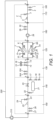
- Figure 1 shows a treatment apparatus 100 comprising a number of treatment modules.
- the treatment apparatus 100 comprises five permanent treatment modules which are:
- the treatment apparatus further comprises a temporary treatment module: 160 Temporary pumping and dosing module.
- the temporary treatment module 160 can be connected and used when system pumps are unavailable for use.
- the treatment module 160 is temporarily connected between modules 110 and 120.
- the treatment module 160 is temporarily located between modules 120 and 140 in place of module 130.
- the treatment apparatus 100 is connected to a heating and cooling system 200 which is a closed loop system (only primary circuit shown and illustrated as a single pipe for simplicity).
- the treatment apparatus 100 is connected such that, in use, system water flows through the first combined sampling and flushing module 110 then to the temporary dosing module 160 (if present) and to the filter module 120.
- the system water then flows to the dosing module 130, the UV module 140 and the second combined sampling and flushing module 150.
- the treatment apparatus 100 comprises the following components:
- the heating and cooling system 200 is a closed system and incorporates a system pump 210 as well as other components (not shown).
- the treatment apparatus 100 is a modular apparatus and the modules are configured to connect to one another by swivel flanged connections A. Modules can be removed as required for maintenance, replacement or upgrade.
- the illustrated treatment apparatus 100 has five permanent modules and one temporary module in other embodiments, not illustrated, one or more modules are omitted. In many cases the temporary dosing module 160 will not be required. In some cases the UV module 140 will not be required for example. In alternative embodiments, not illustrated, one or both of the combined sampling and power flushing modules 110, 150 are replaced by separate sampling modules and power flush modules.
- the combined sampling and power flushing module 110 comprises power flush valves 1, 2 as well as a sampling point valve 3 and a sample stand 5.
- the sample stand 5 comprises a sample container (not illustrated) which holds a collection member (not shown) which comprises a sponge to collect any system water spilt when a sample is being collected.
- Illustrated in Figure 1 is a swan neck flow regulator 4 which is connected to the sampling point valve 3 to allow a sample to be taken.
- the swan neck flow regulator 4 is a removable component and the module 110 is configured to allow a sterilised swan neck flow regulator 4 to be connected each time a sample is required to be taken.
- the combined sampling and power flushing module 150 is similar to module 110 and comprises power flush valves 26, 27 as well as a sampling point valve 23 and a sample stand 25.
- the sample stand 25 comprises a sample container (not illustrated) which holds a collection member (not shown) which comprises a sponge to collect any system water spilt when a sample is being collected.
- Illustrated in Figure 1 is a swan neck flow regulator 24 which is connected to the sampling point valve 23 to allow a sample to be taken.
- the swan neck flow regulator 24 is a removable component and the module 150 is configured to allow a sterilised swan neck flow regulator 24 to be connected each time a sample is required to be taken.
- the filter module 120 comprises two filters F1, F2 which are connected in parallel to one another and which provide the flow path through the filter module 120.
- the filter module 120 thus provides full flow filtration of the system water.
- Each of the filters F1, F2 comprises a 20 micron cartridge filter.
- the filter module 120 comprises filter isolating valves 10, 10A, 6 & 6A allowing one of the filters F1, F2 to be isolated for maintenance or replacement whilst allowing the other filter F1, F2 to continue to provide full flow filtration allowing continued operation of the treatment apparatus 100 and thus of the heating and/or cooling system 200.
- Individual filter drains, 7 & 7A are supplied to allow inspection, maintenance of an individual filter in isolation without disrupting system service.
- the dosing module 130 comprises automatic dosing valves, 13, 14 and pumps 15, 16 and is configured to be connected to a supply of treatment chemicals to be dosed into the system water as required.
- Valves 15A & 16A are future use valves for use with apparatus such as a degasser plant or remote monitoring plant.
- the UV module 140 comprises a UV plant 21 comprising a UV emitter and a parallel by-pass path comprising a regulating valves 20 & 17.
- the UV module 140 further comprises isolating valves 17, 22 allowing the UV plant to be isolated for maintenance or replacement whilst allowing continued operation of the treatment apparatus 100 (without UV irradiation) and thus of the heating and/or cooling system 200.
- Valve 19 is a RPZ valve which allows connection of a water make up and pressurisation unit (not shown).
- the temporary dosing module 160 comprises a temporary pump 28 as well as automatic dosing valves 29, 30 and is configured to be connected to a supply of treatment chemicals to be dosed into the system water as required. This temporary dosing module 160 is intended to only be connected to the remainder of the treatment apparatus 100 when system pumps are not available.
- system water enters the treatment apparatus 100 and first meets valves 1 and 2 (power flush valves) and then passes sampling point valve 3 in module 110. With the configuration shown in Figure 1 the system water then enters temporary dosing module 160 before passing to the filter module 120. However, the connection of the temporary dosing module 160 between module 110 and 160 is temporary and in the normal configuration of the treatment apparatus 100 the temporary dosing module is disconnected and module 120 connects directly to module 110. In that case system water flows from combined testing and power flushing module 110 directly into filter module 120 and flows to filters F1 and F2. Prior to entering the dual filters the water passes isolating valves 6 & 6A, pressure gauge and flow protection switches at points 11 and 11A. Automatic air vents are placed on top of the filter housings, valves 8 & 9.
- the system water flows from module 120 into dosing module 130, the module contains valves 13, 14 which are automatic dosing connection valves to inject chemicals into the system and continues past future use valves 25A, 16A.
- the system water continues into module 140 which contains a regulated UV plant 21 configured to treat 4 times the system volume of water in a 24 hours period.
- the system water is regulated at valve 20 & 17 causing the correct amount of water to pass isolating valve 17 and through the UV plant 21 passed the isolation valve 22.
- the system water then flows to the combined testing and power flushing module 150.
- the treatment apparatus 100 is configured to be connected to a heating and cooling system 200 throughout the life of the system from construction, through commissioning and then long term maintenance.
- the apparatus is configured such that the filters F1 and F2 allow the removal of particles, including fine particles from system water meaning that dynamic flushing need not be performed on the heating and cooling system 200.
- the filter F1 and F2 allow dynamic filtration to be undertaken without the need to flush waste water to drain.
- the modules of the apparatus 100 can be operated as required by a user with some operations automatically controlled by a controller (not shown). An example method of operation is set out below.
- Temporary pumps (not shown) and adequate water storage tanks (not shown) are connected to valves 26, 27 and water is pumped through the closed circuit heating/cooling system 200 to valves 1, 2 where it is discharged via temporary hoses (not shown) to a foul drain (not shown).
- the process removes chemicals and contaminants using the least amount water and the amount of waste water is reduced compared to a dynamic balanced flushing process which is a process which dilutes the system water over a extended period of time.
- the treatment apparatus 100 can be configured to direct system water to flow though the filter module 120.
- Samples of system water are taken from the combined sampling and power flushing modules 110 and 150. To collect samples the following procedure is used:
- Samples are also taken subsequently during and after stages of treatment as necessary to check system water is of acceptable quality. Once the system is operational samples are taken as required to monitor the quality of system water.
- the heating and cooling system is then subjected to conditions to cause pipework contraction and expansion and then final commissioning is performed.
- the system is initially operated in bypass conditions and eventually all plant/equipment is placed in the full flow position.
- Flow rates are manipulated during the process to maximise the amount of available debris for removal.
- the heating and cooling system can be placed to bypass and the system subjected to conditions to cause pipework contraction and expansion such that any released and/or mobilised debris is presented to and removed by the filters at the filter module 120.
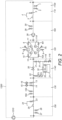
- Figure 2 shows an alternative embodiment of a treatment apparatus 1100 comprising a number of treatment modules.
- the treatment apparatus 1100 comprises five permanent treatment modules which are:
- the treatment apparatus 1100 further comprises a temporary treatment module: 160 Temporary pumping and dosing module.
- the treatment apparatus 1100 of Figure 2 is generally the same as the treatment apparatus 100 of Figure 1 but has a UV module 1140 which differs from the UV module 140 of the treatment apparatus 100.
- the UV module 1140 and dosing module 130 are configured in a different order in treatment apparatus 1100 to that of treatment apparatus 100 with the dosing module 130 lying downstream of the UV module 1140.
- the temporary treatment module 160 can be connected and used when system pumps are unavailable for use.
- the treatment module 160 is temporarily connected between modules 110 and 120.
- the treatment apparatus 1100 is connected to a heating and cooling system 1200 which is a closed loop system (only primary circuit shown and illustrated as a single pipe for simplicity).
- the treatment apparatus 1100 is connected such that, in use, system water flows through the first combined sampling and flushing module 110 then to the temporary dosing module 160 (if present) and to the filter module 120. The system water then flows to the UV module 1140, dosing module 130, and the second combined sampling and flushing module 150.
- the treatment apparatus 1100 comprises the following components:
- the heating and cooling system 1200 is a closed system and incorporates a system pump 1210 as well as other components (not shown).
- the UV module 1140 comprises a UV plant 21 comprising a UV emitter.
- the UV module 1140 further comprises two filters, F3, F4.
- the most upstream of the two filters, F4, is a 1 micron filter and the most downstream, F3, is a 0.25 micron filter.
- the UV module 1140 comprises a first flow path which selectively passes the UV plant 21 and passes through the filters F3, F4 and a second (by-pass) flow path which bypasses the filters F3, F4 and UV plant 21.
- a regulating valve 20 lies on the second (by-pass) flow path.
- the first flow path comprises two branches: a UV emitter branch which comprises valve 34, UV plant 21 and valve 33; and a bypass branch which comprises valve 32.
- the UV module also comprises valves 17, 31 and 22 as well as filters F3, F4 on the first flow path with the filters F3, F4, located on the first flow path after the UV emitter branch and bypass branch meet.
- the UV module 1140 is adapted such that, in use, the flow through the first flow path can be selectively directed through one or both of the UV emitter branch and bypass branch.
- the UV module 1140 is adapted such that the flow through the module can be selectively directed through one or both of the first flow path and/or through the second (by-pass) flow path.
- flow of system water through the UV plant 21 and filters F3, F4 can be managed, in use, so that system water can be selectively: (i) UV irradiated and filtered (ii) filtered without being UV irradiated; (iii) not UV irradiated or filtered; or (iv) a combination thereof.
- preferred embodiments of the present invention may provide an effective apparatus and method for treating heating and/or cooling systems.
Landscapes
- Engineering & Computer Science (AREA)
- Chemical & Material Sciences (AREA)
- Life Sciences & Earth Sciences (AREA)
- Hydrology & Water Resources (AREA)
- Environmental & Geological Engineering (AREA)
- Water Supply & Treatment (AREA)
- Organic Chemistry (AREA)
- Toxicology (AREA)
- Health & Medical Sciences (AREA)
- Physics & Mathematics (AREA)
- Thermal Sciences (AREA)
- Combustion & Propulsion (AREA)
- Mechanical Engineering (AREA)
- General Engineering & Computer Science (AREA)
- Physical Water Treatments (AREA)
- Exposure Of Semiconductors, Excluding Electron Or Ion Beam Exposure (AREA)
Claims (15)
- Aufbereitungsvorrichtung (100), die dazu ausgelegt ist, ein Heiz- und/oder Kühlsystem (200) aufzubereiten, dadurch gekennzeichnet, dass die Aufbereitungsvorrichtung (100) ein Filtermodul (120) und ein oder mehrere andere trennbare Aufbereitungsmodule (110, 130, 140, 150, 160) umfasst und wobei das Filtermodul (120) dazu ausgelegt ist, beim Betrieb einen vollen Strom von Systemwasser aufzunehmen und Partikel aus dem Systemwasser zu entfernen, und wobei die Vorrichtung (100) dazu ausgelegt ist, dass beim Betrieb das gesamte Systemwasser mindestens einmal in einem 24-Stunden-Zeitraum durch einen Filter (F1, F2) fließt, und wobei das Filtermodul (120) zwei parallel geschaltete Filter (F1, F2) und ein oder mehrere Ventile (6, 6A, 10, 10A) umfasst, die so ausgelegt sind, dass sie es ermöglichen, Fluid selektiv so zu leiten, dass es durch einen oder beide Filter (F1, F2) fließt.
- Aufbereitungsvorrichtung (100) gemäß Anspruch 1, wobei die Vorrichtung (100) dazu ausgelegt ist, ein geschlossenes Heiz- und/oder Kühlsystem (200), gegebenenfalls ein HLK-System, aufzubereiten.
- Aufbereitungsvorrichtung (100) gemäß Anspruch 1 oder 2, wobei die Vorrichtung (100) ferner dadurch gekennzeichnet ist, dass die Vorrichtung umfasst:(i) das Filtermodul (120); undein oder mehrere Module, ausgewählt aus:(ii) einem Probenahmemodul;(iii) einem Druckspülmodul;(iv) einem kombinierten Probenahme- und Druckspülmodul (110);(v) einem UV-Modul (140); und(vi) einem Dosiermodul (130); undwobei die Module gegebenenfalls so ausgelegt sind, dass sie miteinander verbunden und voneinander getrennt werden können.
- Aufbereitungsvorrichtung (100) gemäß einem der vorhergehenden Ansprüche, wobei das Filtermodul (120) einen 20-Mikrometer-Filter umfasst.
- Aufbereitungsvorrichtung (100) gemäß einem der vorhergehenden Ansprüche, wobei die Aufbereitungsvorrichtung (100) eine oder mehrere Probenahmestellen umfasst, die so ausgelegt sind, dass beim Betrieb eine Probe des Systemwassers entnommen werden kann, und/oder wobei die Aufbereitungsvorrichtung (100) Druckspülstellen umfasst, die so ausgelegt sind, dass beim Betrieb ein Heiz- und/oder Kühlsystem mit Druck gespült werden kann und/oder wobei die Aufbereitungsvorrichtung (100) einen UV(Ultraviolett)-Strahler umfasst, der dazu ausgelegt ist, beim Betrieb das Systemwasser zu bestrahlen, und/oder wobei die Aufbereitungsvorrichtung (100) einen oder mehrere Dosierstellen umfasst, die so ausgelegt sind, dass beim Betrieb dem Systemwasser ein Aufbereitungsmittel zugesetzt werden kann.
- Vorrichtung (100) gemäß einem der vorhergehenden Ansprüche, wobei die Vorrichtung (100) ein UV-Modul (140) mit einem UV-Strahler und einem oder mehreren Filtern umfasst.
- Vorrichtung (100) gemäß einem der vorhergehenden Ansprüche, wobei die Vorrichtung (100) umfasst:ein Filtermodul (120); undein kombiniertes Probenahme- und Druckspülmodul (110) und/oder ein UV-Modul (140); undein oder mehrere Module, ausgewählt aus:einem Probenahmemodul;einem Druckspülmodul; undeinem kombinierten Probenahme- und Druckspülmodul; undeinem Dosiermodul (130) .
- Vorrichtung (100) gemäß einem der vorhergehenden Ansprüche, wobei die Vorrichtung (100) Aufbereitungsmodule aufweist, die in der folgenden Konfiguration angeordnet sind, beginnend mit dem stromaufwärtigsten Modul in Bezug auf die Strömungsrichtung des Systemwassers:(I) ein kombiniertes Probenahme- und Druckspülmodul (110);(II) ein temporäres Dosier- und/oder Pumpmodul (160), das dazu ausgelegt ist, vor dem normalen Betrieb eines Heiz- und/oder Kühlsystems getrennt zu werden;(III) ein Filtermodul (120);(IV) ein Dosiermodul (130);(V) ein UV-Modul (140); und(VI) ein kombiniertes Probenahme- und Druckspülmodul (110).
- Vorrichtung (100) gemäß einem der vorhergehenden Ansprüche, wobei die Vorrichtung einen 1-Mikrometer-Filter und einen 0,25-Mikrometer-Filter umfasst.
- Vorrichtung (100) gemäß einem der vorhergehenden Ansprüche, wobei die Vorrichtung (100) ein UV-Modul (140) umfasst, das einen UV-Strahler und einen oder mehrere Filter umfasst, und wobei das UV-Modul (140) einen 1-Mikrometer-Filter und einen 0,25-Mikrometer-Filter umfasst.
- Verfahren zum Aufbereiten eines Heiz- und/oder Kühlsystems (200), dadurch gekennzeichnet, dass das Verfahren eine Vollstromfilterung des Systemwassers umfasst, um Partikel aus dem Systemwasser zu entfernen, sodass beim Betrieb das gesamte Systemwasser mindestens einmal in einem Zeitraum von 24 Stunden durch einen Filter fließt, wobei das Verfahren eine Aufbereitungsvorrichtung (100) gemäß einem der Ansprüche 1 bis 8 verwendet.
- Verfahren gemäß Anspruch 11, wobei das Verfahren das Filtern des Systemwassers unter Verwendung eines 20-Mikrometer-Filters umfasst und/oder wobei, das Verfahren das Entfernen von Partikeln aus dem Systemwasser umfasst, ohne eine dynamische Spülung des Heiz- und/oder Kühlsystems (200) durchzuführen, und/oder wobei das Verfahren das Durchführen einer Druckspülung des Systems (200) ohne Filtern umfasst, um Verunreinigungen aus dem System (200) vor dem Durchführen der Filterung zu entfernen, und wobei das Verfahren gegebenenfalls das Filtern des Systemwassers umfasst, um Partikel zu entfernen, die aufgrund der Ausdehnung und Kontraktion von Komponenten des Heiz- und/oder Kühlsystems (200) freigesetzt werden, und wobei das Verfahren gegebenenfalls das Filtern des Systemwassers umfasst, um Partikel zu entfernen, die aufgrund der Ausdehnung und Kontraktion von Komponenten des Heiz- und/oder Kühlsystems (200) im Anschluss an einen Reinigungs- und/oder Spülprozess freigesetzt werden.
- Verfahren gemäß einem der Ansprüche 11 bis 12, wobei das Verfahren umfasst, dass ein Heizsystem (200) Wärme und/oder Kühlung ausgesetzt wird, um eine Ausdehnung und Kontraktion der Systemrohrleitungen zu bewirken, wodurch Partikel freigesetzt und/oder mobilisiert werden, während sich kritische Anlagen und Regelventile im Bypass befinden, und dass das Systemwasser gefiltert wird, um freigesetzte Partikel zu entfernen, bevor die kritischen Anlagen und Steuerventile aus dem Bypass entfernt werden.
- Verfahren gemäß einem der Ansprüche 11 bis 13, wobei das Verfahren ein kontinuierliches Filtern des Systemwassers umfasst, während es beim Betrieb durch das Heiz- und/oder Kühlsystem (200) fließt, und/oder wobei das Verfahren das Installieren einer Aufbereitungsvorrichtung (100) gemäß einem der Ansprüche 1 bis 8 als dauerhaften Teil des Heiz- und/oder Kühlsystems (200) umfasst und/oder wobei das System ein geschlossenes Heiz- und/oder Kühlsystem (200), gegebenenfalls ein HLK-System, umfasst.
- Heiz- und/oder Kühlsystem (200) mit einer daran angeschlossenen Vorrichtung (100) gemäß einem der Ansprüche 1 bis 10, wobei das System gegebenenfalls ein geschlossenes Heiz- und/oder Kühlsystem (200), gegebenenfalls ein HLK-System, umfasst.
Applications Claiming Priority (2)
| Application Number | Priority Date | Filing Date | Title |
|---|---|---|---|
| GBGB1601488.8A GB201601488D0 (en) | 2016-01-27 | 2016-01-27 | Improvements in and relating to heating and cooling systems |
| PCT/GB2017/050211 WO2017129989A2 (en) | 2016-01-27 | 2017-01-27 | Improvements in and relating to heating and cooling systems |
Publications (3)
| Publication Number | Publication Date |
|---|---|
| EP3408232A2 EP3408232A2 (de) | 2018-12-05 |
| EP3408232C0 EP3408232C0 (de) | 2023-10-11 |
| EP3408232B1 true EP3408232B1 (de) | 2023-10-11 |
Family
ID=55535008
Family Applications (1)
| Application Number | Title | Priority Date | Filing Date |
|---|---|---|---|
| EP17704809.7A Active EP3408232B1 (de) | 2016-01-27 | 2017-01-27 | Verbesserungen an oder in zusammenhang mit heiz- und kühlsystemen |
Country Status (4)
| Country | Link |
|---|---|
| EP (1) | EP3408232B1 (de) |
| ES (1) | ES2967875T3 (de) |
| GB (3) | GB201601488D0 (de) |
| WO (1) | WO2017129989A2 (de) |
Families Citing this family (3)
| Publication number | Priority date | Publication date | Assignee | Title |
|---|---|---|---|---|
| GB2566566B (en) * | 2018-02-27 | 2019-09-18 | Vexo International Uk Ltd | Fluid circuit filling apparatus and method |
| GB201903266D0 (en) * | 2019-03-11 | 2019-04-24 | Vexo International Uk Ltd | Apparatus for supplying liquid to a fluid circuit of a heating or a cooling system |
| KR102529315B1 (ko) * | 2021-12-03 | 2023-05-04 | 대림로얄이앤피(주) | 보일러수의 재순환을 위한 필터유닛이 구비된 보일러시스템 |
Family Cites Families (8)
| Publication number | Priority date | Publication date | Assignee | Title |
|---|---|---|---|---|
| DE102005035950A1 (de) * | 2005-07-28 | 2007-01-25 | Sasol Germany Gmbh | Verfahren und Vorrichtung zur Reinigung industrieller Abwässer |
| US7531096B2 (en) * | 2005-12-07 | 2009-05-12 | Arizona Public Service Company | System and method of reducing organic contaminants in feed water |
| GB2491246B (en) * | 2012-05-21 | 2013-05-15 | Adey Holdings 2008 Ltd | Separator device |
| US20130319464A1 (en) * | 2012-06-01 | 2013-12-05 | Peter Derek Barrett | Heat Exchanger Pipework Cleaning Apparatus and Method |
| GB2504537B (en) * | 2012-08-02 | 2015-08-05 | Alpha Fry Ltd | Connection device |
| GB2509714A (en) * | 2013-01-09 | 2014-07-16 | Intaco Ltd | Plumbing diverter component |
| GB2503762B (en) * | 2013-03-06 | 2014-07-02 | Vexo Internat Uk Ltd | Fluid treatment apparatus & method |
| EP2829811B1 (de) * | 2013-07-23 | 2018-05-30 | Caleffi S.p.A. | Ventil für heizungsanlage |
-
2016
- 2016-01-27 GB GBGB1601488.8A patent/GB201601488D0/en not_active Ceased
-
2017
- 2017-01-27 GB GB2112074.6A patent/GB2595602B/en active Active
- 2017-01-27 GB GB1812323.2A patent/GB2563751B/en active Active
- 2017-01-27 WO PCT/GB2017/050211 patent/WO2017129989A2/en not_active Ceased
- 2017-01-27 ES ES17704809T patent/ES2967875T3/es active Active
- 2017-01-27 EP EP17704809.7A patent/EP3408232B1/de active Active
Also Published As
| Publication number | Publication date |
|---|---|
| GB201601488D0 (en) | 2016-03-09 |
| EP3408232A2 (de) | 2018-12-05 |
| EP3408232C0 (de) | 2023-10-11 |
| WO2017129989A2 (en) | 2017-08-03 |
| ES2967875T3 (es) | 2024-05-06 |
| GB2595602A (en) | 2021-12-01 |
| WO2017129989A3 (en) | 2017-08-31 |
| GB201812323D0 (en) | 2018-09-12 |
| WO2017129989A4 (en) | 2017-10-19 |
| GB2595602B (en) | 2022-03-23 |
| GB2563751B (en) | 2021-12-22 |
| GB2563751A (en) | 2018-12-26 |
| GB202112074D0 (en) | 2021-10-06 |
Similar Documents
| Publication | Publication Date | Title |
|---|---|---|
| AU2014224431B2 (en) | Fluid treatment apparatus and method | |
| EP3408232B1 (de) | Verbesserungen an oder in zusammenhang mit heiz- und kühlsystemen | |
| KR101565879B1 (ko) | 사물인터넷 기술 제어방식을 갖는 비점오염저감시설용 유지관리시스템 | |
| US20110017678A1 (en) | Process for Rain Water, HVAC Condensate and Refrigeration Blowdown/Bleed Blowdown/Bleed Water Recovery, Water Quality Monitoring, Real Time Water Treatment and Utilization of Recovered Water | |
| JP2018523565A (ja) | 水濾過のためのシステム及び方法 | |
| EP3962865B1 (de) | System zur abflussfreien wasserbehandlung | |
| US6773582B2 (en) | Drinking water treatment system including hydrogen sulfide scrubber using triazine compound and associated methods | |
| US20060186026A1 (en) | Compact water purification apparatus | |
| JP2021506570A (ja) | 水精製および分注システム、およびかかるシステムの稼働方法 | |
| JP4854603B2 (ja) | 紫外線照射装置 | |
| CN112004590A (zh) | 系统及用于清洁水过滤系统的方法 | |
| Gowthaman et al. | Performance Evaluation of Waste Water Treatment Plant: an analysis of FOG removal efficiency | |
| WO2023085936A1 (en) | Water treatment system and water treatment method | |
| CN220642682U (zh) | 一种雨水回用系统 | |
| Vinci et al. | FOG–figuring out good solution to fats, oils and grease in advanced wastewater treatment systems | |
| US20190315634A1 (en) | Water reclaim method and system | |
| KR20210051184A (ko) | 축산 분뇨 처리 장치 | |
| KR20240107272A (ko) | 수도용 여과장치 운용 시스템 | |
| JP5031116B2 (ja) | 紫外線照射装置 | |
| WO2012051987A1 (de) | Vorrichtung zur abluftreinigung mittels uv-strahlung und verfahren zur reinigung der vorrichtung | |
| Fischer et al. | Quenching Thornton’s Thirst | |
| Bloetscher et al. | Pembroke Pines Explores Aquifer Recharge as a Cost-Effective Alternative Water Supply Strategy | |
| JP2005177687A (ja) | 製造ライン洗浄システム | |
| Barash et al. | Bioremediation: Wastewater treatment in diesel power stations | |
| KR20100082990A (ko) | 자동 유지관리 가능한 폐수 정화 장치 |
Legal Events
| Date | Code | Title | Description |
|---|---|---|---|
| STAA | Information on the status of an ep patent application or granted ep patent |
Free format text: STATUS: UNKNOWN |
|
| STAA | Information on the status of an ep patent application or granted ep patent |
Free format text: STATUS: THE INTERNATIONAL PUBLICATION HAS BEEN MADE |
|
| PUAI | Public reference made under article 153(3) epc to a published international application that has entered the european phase |
Free format text: ORIGINAL CODE: 0009012 |
|
| STAA | Information on the status of an ep patent application or granted ep patent |
Free format text: STATUS: REQUEST FOR EXAMINATION WAS MADE |
|
| 17P | Request for examination filed |
Effective date: 20180727 |
|
| AK | Designated contracting states |
Kind code of ref document: A2 Designated state(s): AL AT BE BG CH CY CZ DE DK EE ES FI FR GB GR HR HU IE IS IT LI LT LU LV MC MK MT NL NO PL PT RO RS SE SI SK SM TR |
|
| AX | Request for extension of the european patent |
Extension state: BA ME |
|
| DAV | Request for validation of the european patent (deleted) | ||
| DAX | Request for extension of the european patent (deleted) | ||
| STAA | Information on the status of an ep patent application or granted ep patent |
Free format text: STATUS: EXAMINATION IS IN PROGRESS |
|
| 17Q | First examination report despatched |
Effective date: 20200402 |
|
| GRAP | Despatch of communication of intention to grant a patent |
Free format text: ORIGINAL CODE: EPIDOSNIGR1 |
|
| STAA | Information on the status of an ep patent application or granted ep patent |
Free format text: STATUS: GRANT OF PATENT IS INTENDED |
|
| INTG | Intention to grant announced |
Effective date: 20230420 |
|
| GRAS | Grant fee paid |
Free format text: ORIGINAL CODE: EPIDOSNIGR3 |
|
| GRAA | (expected) grant |
Free format text: ORIGINAL CODE: 0009210 |
|
| STAA | Information on the status of an ep patent application or granted ep patent |
Free format text: STATUS: THE PATENT HAS BEEN GRANTED |
|
| RBV | Designated contracting states (corrected) |
Designated state(s): AL AT BE BG CH CY CZ DE DK EE ES FI FR GR HR HU IE IS IT LI LT LU LV MC MK MT NL NO PL PT RO RS SE SI SK SM TR |
|
| AK | Designated contracting states |
Kind code of ref document: B1 Designated state(s): AL AT BE BG CH CY CZ DE DK EE ES FI FR GR HR HU IE IS IT LI LT LU LV MC MK MT NL NO PL PT RO RS SE SI SK SM TR |
|
| RBV | Designated contracting states (corrected) |
Designated state(s): AL AT BE BG CH CY CZ DE DK EE ES FI FR GR HR HU IE IS IT LI LT LU LV MC MK MT NL NO PL PT RO RS SE SI SK SM TR |
|
| REG | Reference to a national code |
Ref country code: CH Ref legal event code: EP |
|
| REG | Reference to a national code |
Ref country code: DE Ref legal event code: R096 Ref document number: 602017075142 Country of ref document: DE |
|
| REG | Reference to a national code |
Ref country code: IE Ref legal event code: FG4D |
|
| U01 | Request for unitary effect filed |
Effective date: 20231107 |
|
| U07 | Unitary effect registered |
Designated state(s): AT BE BG DE DK EE FI FR IT LT LU LV MT NL PT SE SI Effective date: 20231113 |
|
| U20 | Renewal fee for the european patent with unitary effect paid |
Year of fee payment: 8 Effective date: 20231113 |
|
| PG25 | Lapsed in a contracting state [announced via postgrant information from national office to epo] |
Ref country code: GR Free format text: LAPSE BECAUSE OF FAILURE TO SUBMIT A TRANSLATION OF THE DESCRIPTION OR TO PAY THE FEE WITHIN THE PRESCRIBED TIME-LIMIT Effective date: 20240112 |
|
| PG25 | Lapsed in a contracting state [announced via postgrant information from national office to epo] |
Ref country code: IS Free format text: LAPSE BECAUSE OF FAILURE TO SUBMIT A TRANSLATION OF THE DESCRIPTION OR TO PAY THE FEE WITHIN THE PRESCRIBED TIME-LIMIT Effective date: 20240211 |
|
| PG25 | Lapsed in a contracting state [announced via postgrant information from national office to epo] |
Ref country code: IS Free format text: LAPSE BECAUSE OF FAILURE TO SUBMIT A TRANSLATION OF THE DESCRIPTION OR TO PAY THE FEE WITHIN THE PRESCRIBED TIME-LIMIT Effective date: 20240211 Ref country code: GR Free format text: LAPSE BECAUSE OF FAILURE TO SUBMIT A TRANSLATION OF THE DESCRIPTION OR TO PAY THE FEE WITHIN THE PRESCRIBED TIME-LIMIT Effective date: 20240112 |
|
| REG | Reference to a national code |
Ref country code: ES Ref legal event code: FG2A Ref document number: 2967875 Country of ref document: ES Kind code of ref document: T3 Effective date: 20240506 |
|
| PG25 | Lapsed in a contracting state [announced via postgrant information from national office to epo] |
Ref country code: RS Free format text: LAPSE BECAUSE OF FAILURE TO SUBMIT A TRANSLATION OF THE DESCRIPTION OR TO PAY THE FEE WITHIN THE PRESCRIBED TIME-LIMIT Effective date: 20231011 Ref country code: PL Free format text: LAPSE BECAUSE OF FAILURE TO SUBMIT A TRANSLATION OF THE DESCRIPTION OR TO PAY THE FEE WITHIN THE PRESCRIBED TIME-LIMIT Effective date: 20231011 Ref country code: NO Free format text: LAPSE BECAUSE OF FAILURE TO SUBMIT A TRANSLATION OF THE DESCRIPTION OR TO PAY THE FEE WITHIN THE PRESCRIBED TIME-LIMIT Effective date: 20240111 Ref country code: HR Free format text: LAPSE BECAUSE OF FAILURE TO SUBMIT A TRANSLATION OF THE DESCRIPTION OR TO PAY THE FEE WITHIN THE PRESCRIBED TIME-LIMIT Effective date: 20231011 |
|
| REG | Reference to a national code |
Ref country code: DE Ref legal event code: R097 Ref document number: 602017075142 Country of ref document: DE |
|
| PG25 | Lapsed in a contracting state [announced via postgrant information from national office to epo] |
Ref country code: CZ Free format text: LAPSE BECAUSE OF FAILURE TO SUBMIT A TRANSLATION OF THE DESCRIPTION OR TO PAY THE FEE WITHIN THE PRESCRIBED TIME-LIMIT Effective date: 20231011 |
|
| PG25 | Lapsed in a contracting state [announced via postgrant information from national office to epo] |
Ref country code: SK Free format text: LAPSE BECAUSE OF FAILURE TO SUBMIT A TRANSLATION OF THE DESCRIPTION OR TO PAY THE FEE WITHIN THE PRESCRIBED TIME-LIMIT Effective date: 20231011 |
|
| PG25 | Lapsed in a contracting state [announced via postgrant information from national office to epo] |
Ref country code: SM Free format text: LAPSE BECAUSE OF FAILURE TO SUBMIT A TRANSLATION OF THE DESCRIPTION OR TO PAY THE FEE WITHIN THE PRESCRIBED TIME-LIMIT Effective date: 20231011 Ref country code: SK Free format text: LAPSE BECAUSE OF FAILURE TO SUBMIT A TRANSLATION OF THE DESCRIPTION OR TO PAY THE FEE WITHIN THE PRESCRIBED TIME-LIMIT Effective date: 20231011 Ref country code: RO Free format text: LAPSE BECAUSE OF FAILURE TO SUBMIT A TRANSLATION OF THE DESCRIPTION OR TO PAY THE FEE WITHIN THE PRESCRIBED TIME-LIMIT Effective date: 20231011 Ref country code: CZ Free format text: LAPSE BECAUSE OF FAILURE TO SUBMIT A TRANSLATION OF THE DESCRIPTION OR TO PAY THE FEE WITHIN THE PRESCRIBED TIME-LIMIT Effective date: 20231011 |
|
| PLBE | No opposition filed within time limit |
Free format text: ORIGINAL CODE: 0009261 |
|
| STAA | Information on the status of an ep patent application or granted ep patent |
Free format text: STATUS: NO OPPOSITION FILED WITHIN TIME LIMIT |
|
| PG25 | Lapsed in a contracting state [announced via postgrant information from national office to epo] |
Ref country code: MC Free format text: LAPSE BECAUSE OF FAILURE TO SUBMIT A TRANSLATION OF THE DESCRIPTION OR TO PAY THE FEE WITHIN THE PRESCRIBED TIME-LIMIT Effective date: 20231011 |
|
| PG25 | Lapsed in a contracting state [announced via postgrant information from national office to epo] |
Ref country code: MC Free format text: LAPSE BECAUSE OF FAILURE TO SUBMIT A TRANSLATION OF THE DESCRIPTION OR TO PAY THE FEE WITHIN THE PRESCRIBED TIME-LIMIT Effective date: 20231011 |
|
| REG | Reference to a national code |
Ref country code: CH Ref legal event code: PL |
|
| 26N | No opposition filed |
Effective date: 20240712 |
|
| PG25 | Lapsed in a contracting state [announced via postgrant information from national office to epo] |
Ref country code: CH Free format text: LAPSE BECAUSE OF NON-PAYMENT OF DUE FEES Effective date: 20240131 |
|
| PG25 | Lapsed in a contracting state [announced via postgrant information from national office to epo] |
Ref country code: CH Free format text: LAPSE BECAUSE OF NON-PAYMENT OF DUE FEES Effective date: 20240131 |
|
| U20 | Renewal fee for the european patent with unitary effect paid |
Year of fee payment: 9 Effective date: 20250102 |
|
| PGFP | Annual fee paid to national office [announced via postgrant information from national office to epo] |
Ref country code: ES Payment date: 20250226 Year of fee payment: 9 |
|
| PGFP | Annual fee paid to national office [announced via postgrant information from national office to epo] |
Ref country code: IE Payment date: 20250130 Year of fee payment: 9 |
|
| PG25 | Lapsed in a contracting state [announced via postgrant information from national office to epo] |
Ref country code: CY Free format text: LAPSE BECAUSE OF FAILURE TO SUBMIT A TRANSLATION OF THE DESCRIPTION OR TO PAY THE FEE WITHIN THE PRESCRIBED TIME-LIMIT; INVALID AB INITIO Effective date: 20170127 |
|
| PG25 | Lapsed in a contracting state [announced via postgrant information from national office to epo] |
Ref country code: HU Free format text: LAPSE BECAUSE OF FAILURE TO SUBMIT A TRANSLATION OF THE DESCRIPTION OR TO PAY THE FEE WITHIN THE PRESCRIBED TIME-LIMIT; INVALID AB INITIO Effective date: 20170127 |
|
| PG25 | Lapsed in a contracting state [announced via postgrant information from national office to epo] |
Ref country code: TR Free format text: LAPSE BECAUSE OF FAILURE TO SUBMIT A TRANSLATION OF THE DESCRIPTION OR TO PAY THE FEE WITHIN THE PRESCRIBED TIME-LIMIT Effective date: 20231011 |
|
| U20 | Renewal fee for the european patent with unitary effect paid |
Year of fee payment: 10 Effective date: 20251229 |