EP3407939B1 - Unité piston créant des signaux audio intermittents et dispositif d'administration de médicament comprenant l'unité - Google Patents
Unité piston créant des signaux audio intermittents et dispositif d'administration de médicament comprenant l'unité Download PDFInfo
- Publication number
- EP3407939B1 EP3407939B1 EP16819101.3A EP16819101A EP3407939B1 EP 3407939 B1 EP3407939 B1 EP 3407939B1 EP 16819101 A EP16819101 A EP 16819101A EP 3407939 B1 EP3407939 B1 EP 3407939B1
- Authority
- EP
- European Patent Office
- Prior art keywords
- plunger
- rod
- striker
- biasing member
- head
- Prior art date
- Legal status (The legal status is an assumption and is not a legal conclusion. Google has not performed a legal analysis and makes no representation as to the accuracy of the status listed.)
- Active
Links
- 239000003814 drug Substances 0.000 title claims description 30
- 230000005236 sound signal Effects 0.000 title description 7
- 238000000429 assembly Methods 0.000 description 3
- 238000011084 recovery Methods 0.000 description 3
- 230000011664 signaling Effects 0.000 description 3
- 238000002347 injection Methods 0.000 description 2
- 239000007924 injection Substances 0.000 description 2
- 238000000034 method Methods 0.000 description 2
- 238000012986 modification Methods 0.000 description 2
- 230000004048 modification Effects 0.000 description 2
- 230000007423 decrease Effects 0.000 description 1
- 230000001419 dependent effect Effects 0.000 description 1
- 239000000463 material Substances 0.000 description 1
Images


Classifications
-
- A—HUMAN NECESSITIES
- A61—MEDICAL OR VETERINARY SCIENCE; HYGIENE
- A61M—DEVICES FOR INTRODUCING MEDIA INTO, OR ONTO, THE BODY; DEVICES FOR TRANSDUCING BODY MEDIA OR FOR TAKING MEDIA FROM THE BODY; DEVICES FOR PRODUCING OR ENDING SLEEP OR STUPOR
- A61M5/00—Devices for bringing media into the body in a subcutaneous, intra-vascular or intramuscular way; Accessories therefor, e.g. filling or cleaning devices, arm-rests
- A61M5/178—Syringes
- A61M5/31—Details
- A61M5/315—Pistons; Piston-rods; Guiding, blocking or restricting the movement of the rod or piston; Appliances on the rod for facilitating dosing ; Dosing mechanisms
- A61M5/31511—Piston or piston-rod constructions, e.g. connection of piston with piston-rod
-
- A—HUMAN NECESSITIES
- A61—MEDICAL OR VETERINARY SCIENCE; HYGIENE
- A61M—DEVICES FOR INTRODUCING MEDIA INTO, OR ONTO, THE BODY; DEVICES FOR TRANSDUCING BODY MEDIA OR FOR TAKING MEDIA FROM THE BODY; DEVICES FOR PRODUCING OR ENDING SLEEP OR STUPOR
- A61M5/00—Devices for bringing media into the body in a subcutaneous, intra-vascular or intramuscular way; Accessories therefor, e.g. filling or cleaning devices, arm-rests
- A61M5/178—Syringes
- A61M5/20—Automatic syringes, e.g. with automatically actuated piston rod, with automatic needle injection, filling automatically
- A61M2005/2006—Having specific accessories
- A61M2005/2013—Having specific accessories triggering of discharging means by contact of injector with patient body
-
- A—HUMAN NECESSITIES
- A61—MEDICAL OR VETERINARY SCIENCE; HYGIENE
- A61M—DEVICES FOR INTRODUCING MEDIA INTO, OR ONTO, THE BODY; DEVICES FOR TRANSDUCING BODY MEDIA OR FOR TAKING MEDIA FROM THE BODY; DEVICES FOR PRODUCING OR ENDING SLEEP OR STUPOR
- A61M2205/00—General characteristics of the apparatus
- A61M2205/58—Means for facilitating use, e.g. by people with impaired vision
- A61M2205/581—Means for facilitating use, e.g. by people with impaired vision by audible feedback
-
- A—HUMAN NECESSITIES
- A61—MEDICAL OR VETERINARY SCIENCE; HYGIENE
- A61M—DEVICES FOR INTRODUCING MEDIA INTO, OR ONTO, THE BODY; DEVICES FOR TRANSDUCING BODY MEDIA OR FOR TAKING MEDIA FROM THE BODY; DEVICES FOR PRODUCING OR ENDING SLEEP OR STUPOR
- A61M2205/00—General characteristics of the apparatus
- A61M2205/58—Means for facilitating use, e.g. by people with impaired vision
- A61M2205/582—Means for facilitating use, e.g. by people with impaired vision by tactile feedback
Definitions
- This invention generally relates to an automated medicament delivery device, and more particularly to such a device having a plunger unit which is able to create intermittent audio signals.
- the patent application WO 2011-123024 discloses a related medicament delivery device.
- the patent US 7,758,550 discloses a signaling unit.
- the conventional signaling unit 1 includes a catch rod 11 on which a plurality of unidirectional ratchet teeth 111 are formed and an engaging sleeve 12 whose end is bent inwards to form a flexible engaging portion 121.
- the catch rod 11 is received in the engaging sleeve 12.
- the flexible engaging portion 121 slides from one ratchet tooth 111 to next ratchet tooth 111 and strikes the next ratchet tooth 111 to create an acoustic signal for the user.
- the catch rod 11 is difficult to mount in the engaging sleeve 12 because the ratchet teeth 111 of the catch rod 11 are unidirectional and the inner diameter of the engaging portion 121 of the engaging sleeve 12 is normally smaller than the outer diameter of the ratchet teeth 111. Therefore, the engaging portion 121 will be blocked by the ratchet teeth 111 when the catch rod 11 is inserted into the engaging sleeve 12 unless the flexible engaging portion 121 is temporarily bent outwards.
- this invention relates to a plunger unit and a medicament delivery device having the plunger unit, which is intended to obviate one or more of the problems arising from the limitations and disadvantages encountered in the prior art.
- One object of this invention is to provide a medicament delivery device which can create intermittent audio signals and/or tactile feedback during injection.
- Another object of this invention is to provide a medicament delivery device which is easy to assemble.
- Yet another object of this invention is to provide a medicament delivery device which can inject a highly viscous content.
- a further object of this invention is to provide a medicament delivery device which is compact.
- a plunger unit comprises: a plunger body; a rod member movably mounted to the plunger body; and a first biasing member including two ends which respectively urges the plunger body and the rod member; and is characterized in that a striker is movably mounted between the plunger body and the rod member, wherein the striker impacts the plunger body or the rod member to create signals when the first biasing member activates a movement of the plunger body relative to the rod member.
- the plunger unit further comprises a second biasing member urging the striker and the plunger body.
- the second biasing member may make the audio signals loud and/or tactile feedback clear.
- the plunger unit further comprises a blocker connected to the plunger body and the second biasing member urging the striker and the blocker.
- the striker and the second biasing member are movably received in the plunger body and the first biasing member is sleeved outside the plunger body. Since the first biasing member is arranged outside the plunger body rather than inside the plunger body, the recovery force of the first biasing member with larger dimensions is large enough to expel a highly viscous medicament from a container.
- the plunger body includes a plunger head.
- a plunger sleeve connected to the plunger head and a plug received in the plunger sleeve.
- the striker and the second biasing member are received in the plunger sleeve and the first biasing member is sleeved outside the plunger sleeve.
- the rod member passes through the second biasing member and the striker.
- the rod member includes a rod body and a plurality of bumps on the rod body.
- the rod body passes through the second biasing member and the striker.
- the bumps interfere with the striker when the striker is moved along the rod body.
- the striker is C-shaped and/or has a wedge-shaped rib to facilitate the striker sliding over a bump of the rod member.
- the striker is in a ring and/or has a wedge-shaped rib to facilitate the striker sliding over a bump of the rod member.
- the rod member further includes a rod head from which the rod body extends.
- the first biasing member urges the rod head and the plunger body.
- the rod member includes a rod head, a rod body extending from the rod head, and a plurality of bumps on the rod body.
- the first biasing member urges the rod head and the plunger head.
- a medicament delivery device comprising: a proximal sub-assembly; and a distal sub-assembly movably connected to the proximal sub-assembly.
- the distal sub-assembly includes: a main body; an actuation member sleeved on the main body; and a plunger unit received in the main body; characterized in that the plunger unit is the unit described above.
- the main body includes an arm which is releasably engaged with the plunger body to hold the plunger unit to the main body.
- proximal part/end refers to the part/end of the medicament delivery device, or the parts/ends of the members thereof, which is/are located closest to the medicament delivery site of a patient.
- distal part/end refers to the part/end of the medicament delivery device, or the parts/ends of the members thereof, which is/are located farthest away from the medicament delivery site of the patient.
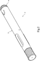
- a medicament delivery device 2 comprises a proximal sub-assembly 3, a distal sub-assembly 4 and an intermediate sub-assembly 5 which is arranged between the proximal sub-assembly 3 and the distal sub-assembly 4.
- the present invention will focus on the distal sub-assembly 4.
- the structure of the present invention which is the same as, or similar to, that disclosed in the WO 2011-123024A1 may be omitted from this specification.
- the intermediate sub-assembly 5 may include a container 51, a cannula 52 connected to a proximal end of the container 51, and a stopper 53 which is slidably received in the container 51.
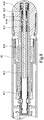
- the distal sub-assembly 4 may include a main body 42, a plunger unit 41 slidably received in the main body 42, and an actuation member 43 sleeved on the main body 42.
- the main body 42 may include a hollow cylinder 421 and a flexible arm 422, which constitutes a portion of the cylinder 421, with an inward barb 423 at the free end of the arm 422.
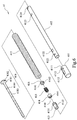
- the plunger unit 41 may include a hollow plunger head 411, a slender plunger sleeve 412, a c-shaped plug 413, a ring-shaped striker 414, a second biasing member 415, a c-shaped blocker 416, a first biasing member 417 and a rod member 418.
- the plunger head 411 is formed with a closed end at the proximal end thereof, an open end 4111 at the distal end thereof, a cylindrical wall between the closed end and the open end 4111, two flexible tabs 4112 which constitute a portion of the wall and respectively have inward barbs at the free ends of the tabs 4112, and two holes 4113 respectively between the tabs 4112 and the open end 4111.
- the plunger sleeve 412 has, on its cylindrical wall in sequence, with two first orifices 4121 and two second orifices 4122 near the proximal end thereof and two third orifices 4123 and two fourth orifices 4124 near the distal end thereof.
- the plug 413 is formed with two outward protrusions 4131 on a cylindrical wall thereof, and a slit 4132 longitudinally extending along the entire length of the wall to make the plug 413 have a c-shaped cross section.
- the striker 414 is formed with at least one wedge-shaped inward rib 4141 on an inner surface thereof.
- the thickness of the wedge-shaped rib 4141 gradually decreases in a direction from the proximal end to the distal end of the striker 414.
- the striker 414 has four ribs 4141.
- the ribs 4141 are symmetrically arranged around the inner surface of the striker 414.
- the blocker 416 is formed with two outward ledges 4161 on cylindrical wall thereof, and a gap 4162 longitudinally extending along the entire length of the wall to make the blocker 416 have a c-shaped cross section.
- the rod member 418 is formed with a disc-shaped rod head 4181, two notches 4182 on the rod head 4181, a rod body 4183 extending proximally from the center of the rod head 4181, and a plurality of ring-shaped bumps 4184 are formed along the length of the rod body 4183, and are equidistantly spaced from each other.
- the proximal end of the plunger sleeve 412 is inserted into the plunger head 411 through the open end 4111 of the plunger head 411 to the extent that the barbs of the tabs 4112 of the plunger head 411 snap into the first orifices 4121 of the plunger sleeve 412 and the holes 4113 of the plunger head 411 are aligned with the second orifices 4122 of the plunger sleeve 412.
- the plug 413 is put into the plunger sleeve 412 through the distal end thereof.
- the C-shaped cross section of the plug 413 renders the plug 413 flexibility such that the plug 413 can be pressed into the plunger sleeve 412 and then expand to make the protrusions 4131 of the plug 413 be received in the third orifices 4123.
- the striker 414 and the second biasing member 415 are, in order, inserted into the plunger sleeve 412 through the distal end thereof. Outer diameters of the striker 414 and the second biasing member 415 are smaller than inner diameter of the plunger sleeve 412 so that the striker 414 and second biasing member 415 are slidable within the plunger sleeve 412.
- the blocker 416 is set to the distal end of the plunger sleeve 412.
- the blocker 416 is similar to the plug 413, i.e. the blocker 416 has a flexible C-shaped cross section to allow the blocker 416 to be pressed into the plunger sleeve 412 and then expand and make the ledges 4161 of the blocker 416 be received in the fourth orifices 4124.
- first biasing member 417 is sleeved on the plunger sleeve 412 such that the proximal end of the first biasing member 417 contacts the distal end of the plunger head 411.
- rod member 418 is inserted into the plunger sleeve 412 through central bores of the blocker 416, second biasing member 415, striker 414 and plug 413 until the rod head 4181 of the rod member 418 contacts the distal end of the first biasing member 417 to complete the assembling of the plunger unit 41.
- the plunger unit 41 is then inserted into the main body 42 to the extent that the notches 4182 of the rod member 418 are engaged with bulges (not shown) inside the main body 42 and the barbs 423 of the arms 422 of the main body 42 snap into the holes 4113 of the plunger head 411 so as to hold the plunger unit 411 to the main body 42 and maintain the first biasing member 417 in a compressed state.
- the rod member 418 is first inserted into the main body 42, followed by the first resilient member 417 and then the spring guide rod assembly (411, 412, 413, 414, 415 and 416).
- the rod member 418 can be first coupled with the main body 42 to form the first sub-unit.
- the first resilient member 417 is coupled with the spring guide rod assembly (411, 412, 413, 414, 415 and 416) to form the second sub-unit.
- the first sub-assembly is coupled to the second sub-assembly to complete the assembling.
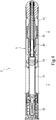
- Figs. 4 and 5 show the medicament delivery device in a state before being used.
- the proximal sub-assembly 3 pushes the actuation member 43 to move in the distal direction so as to release the barbs 423 of the arms 422 of the main body 42 from the holes 4113 of the plunger head 411.
- the recovery force of the first biasing member 417 pushes the rod head 4181 of the rod member 418 in the distal direction and against the main body 42 and, on the other hand, pushes the plunger head 411 together the plunger sleeve 412, plug 413 and blocker 416 to move in the proximal direction.
- the plunger head 411 may push the stopper 53 of the intermediate sub-assembly 5 to deliver the medicament within the container 51 though the cannula 52.
- the blocker 416 also pushes the second biasing member 415 and the striker 414 sliding in the proximal direction.
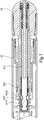
- the striker 414 and the second biasing member 415 will be temporarily obstructed by one of the bumps 4184 because the radius of each ring-shaped bump 4184 is almost equal to the distance from the center of the striker 414 to the portion with the largest thickness of the rib 4141.
- the striker 414 and the rod member 418 being made of material, such as plastic, with a little bit of resilience, the striker 414, which is obstructed by the bump 4184, will eventually be forced to slide over the bump 4184 of the rod member 418 when the blocker 416 together with the plunger sleeve 412 are consecutively moved in the proximal direction by the first biasing member 417.
- the recovery force of the second biasing member 415 will push the striker 414 to quickly move in the proximal direction. Then, the striker 414 will impact the distal end of the plug 413 or next bump 4184 of the rod member 418 to create an audio signal or vibration (tactile feedback) for the user during the process of injection.
- the plunger head 411 and plunger sleeve 412 may be integrally formed as a single member called a " plunger body" .
- the plunger head 411, plunger sleeve 412 and plug 413 may be integrally formed as a single member called a " plunger body" .
- the distal end of the plunger sleeve 412 may be bent inwards by a process to confine the second biasing member 415 within the plunger sleeve 412.
- the blocker 416 may be omitted.
- the striker 414 may be formed with a C-shape to make the striker 414 flexible and facilitate the striker 414 sliding over the bump 4184 of the rod member 418.
- the striker 414 has no rib 4141.
- the cross section of the inner surface of the striker 414 may be in the shape of a wedge.
- the inner diameter of the striker 414 may gradually increase in the direction from the proximal end to the distal end.
- the second biasing member 415 may be an integral part of the striker 414.
- the striker 414 comprises a resilient structure (not shown) integral therewith.
- the resilient structure accelerates the movement of the striker 414 after the striker 414 slides over the bump 4184 of the rod member 418, the audio signals (or tactile feedback) are created by the impact of the striker 414 on the next bump 4184 of the rod member 418.
- the distances of two adjacent bumps 4184 of the rod member 418 may be equal or different through the whole rod body 4183 depending on the user' s need of time intervals of audio signals (or tactile feedbacks).
- the medicament delivery device 2 may be alternatively performed with two sub-assemblies.
- the intermediate sub-assembly 5 may be incorporated with the proximal sub-assembly 3 so that the medicament delivery device 2 may merely comprise two sub-assemblies (i.e. a proximal sub-assembly 3 and a distal sub-assembly 4).
Landscapes
- Health & Medical Sciences (AREA)
- Vascular Medicine (AREA)
- Engineering & Computer Science (AREA)
- Anesthesiology (AREA)
- Biomedical Technology (AREA)
- Heart & Thoracic Surgery (AREA)
- Hematology (AREA)
- Life Sciences & Earth Sciences (AREA)
- Animal Behavior & Ethology (AREA)
- General Health & Medical Sciences (AREA)
- Public Health (AREA)
- Veterinary Medicine (AREA)
- Infusion, Injection, And Reservoir Apparatuses (AREA)
Claims (13)
- Unité piston (41) comprenant :un élément tige (418)un corps de piston (411, 412, 413) monté mobile par rapport à l'élément tige (418) ; etun premier élément de sollicitation (417) incluant deux extrémités qui agit respectivement sur le corps de piston (411, 412, 413) et l'élément tige (418) ;caractérisée en ce queun percuteur (414) est monté mobile entre le corps de piston (411, 412, 413) et l'élément tige (418),le percuteur (414) frappant le corps de piston (411, 412, 413) ou l'élément tige (418) pour créer des signaux lorsque le premier élément de sollicitation (417) active un mouvement du corps de piston (411, 412, 413) par rapport à l'élément tige (418).
- Unité piston selon la revendication 1, l'unité piston (41) comprenant en outre un second élément de sollicitation (415) agissant sur le percuteur (414) et le corps de piston (411, 412, 413).
- Unité piston selon la revendication 2, dans laquelle le second élément de sollicitation fait partie intégrante du percuteur (414).
- Unité piston selon la revendication 2 ou la revendication 3, l'unité piston (41) comprenant un outre un bloqueur (416) relié au corps de piston (411, 412, 413) et au second élément de sollicitation (415) agissant sur le percuteur (414) et le bloqueur (416).
- Unité piston selon les revendications 2 à 4, dans laquelle le percuteur (414) et le second élément de sollicitation (415) sont logés mobiles dans le corps de piston (411, 412, 413) et le premier élément de sollicitation (417) est emmanché à l'extérieur du corps de piston (411, 412, 413).
- Unité piston selon la revendication 5,
dans laquelle le corps de piston (411, 412, 413) inclut une tête de piston (411), un manchon de piston (412) relié à la tête de piston (411) et un bouchon (413) logé dans le manchon de piston (412),
dans laquelle le percuteur (414) et le second élément de sollicitation (415) sont logés dans le manchon de piston (412) et le premier élément de sollicitation (417) est emmanché à l'extérieur du manchon de piston (412), et
dans laquelle l'élément tige (418) passe à travers le second élément de sollicitation (415) et le percuteur (414). - Unité piston selon la revendication 5,
dans laquelle l'élément tige (418) inclut un corps de tige (4181) et une pluralité de bosses (4184) sur le corps de tige (4181),
dans laquelle le corps de tige (4183) passe à travers le second élément de sollicitation (415) et le percuteur (414), et
dans laquelle les bosses (4184) interfèrent avec le percuteur (414) lorsque le percuteur (414) est déplacé le long du corps de tige (4183). - Unité piston selon la revendication 7, dans laquelle le percuteur (414) est en forme de C et/ou comporte une nervure cunéiforme (4141).
- Unité piston selon la revendication 7, dans laquelle le percuteur (414) est de forme annulaire et/ou comporte une nervure cunéiforme (4141).
- Unité piston selon la revendication 7,
dans laquelle l'élément tige (418) inclut en outre une tête de tige (4181) à partir de laquelle s'étend le corps de tige (4183), et
dans laquelle le premier élément de sollicitation (417) agit sur la tête de tige (4181) et le corps de piston (411, 412, 413). - Unité piston selon la revendication 6,
dans laquelle l'élément tige (418) inclut en outre une tête de tige (4181), un corps de tige (4183) s'étendant à partir de la tête de tige (4181) et une pluralité de bosses (4184) sur le corps de tige (4183), et
dans laquelle le premier élément de sollicitation (417) agit sur la tête de tige (4181) et la tête de piston (411). - Dispositif de distribution de médicament (2) comprenant :un sous-ensemble proximal (3) ; etun sous-ensemble distal (4) relié mobile au sous-ensemble proximal (3) et incluant :un corps principal (42) ;un élément d'actionnement (43) emmanché sur le corps principal (42) ; etune unité piston (41) logée dans le corps principal (42) ;caractérisé en ce que :
l'unité piston (41) est l'unité revendiquée dans l'une quelconque des revendications 1 à 9. - Dispositif de distribution de médicament selon la revendication 12, dans lequel le corps principal (42) inclut un bras (422) qui s'engage de manière amovible avec le corps de piston (411, 412, 413) afin de retenir l'unité piston (41) sur le corps principal (42).
Applications Claiming Priority (2)
| Application Number | Priority Date | Filing Date | Title |
|---|---|---|---|
| SE1650085 | 2016-01-26 | ||
| PCT/EP2016/082409 WO2017129337A1 (fr) | 2016-01-26 | 2016-12-22 | Unité piston créant des signaux audio intermittents et dispositif d'administration de médicament comprenant l'unité |
Publications (2)
| Publication Number | Publication Date |
|---|---|
| EP3407939A1 EP3407939A1 (fr) | 2018-12-05 |
| EP3407939B1 true EP3407939B1 (fr) | 2019-10-23 |
Family
ID=57614382
Family Applications (1)
| Application Number | Title | Priority Date | Filing Date |
|---|---|---|---|
| EP16819101.3A Active EP3407939B1 (fr) | 2016-01-26 | 2016-12-22 | Unité piston créant des signaux audio intermittents et dispositif d'administration de médicament comprenant l'unité |
Country Status (4)
| Country | Link |
|---|---|
| US (1) | US11040145B1 (fr) |
| EP (1) | EP3407939B1 (fr) |
| TW (1) | TWI627980B (fr) |
| WO (1) | WO2017129337A1 (fr) |
Families Citing this family (1)
| Publication number | Priority date | Publication date | Assignee | Title |
|---|---|---|---|---|
| KR102682087B1 (ko) * | 2023-03-08 | 2024-07-05 | 주식회사 비에스엘 | 자동 약물 주입 장치 |
Family Cites Families (3)
| Publication number | Priority date | Publication date | Assignee | Title |
|---|---|---|---|---|
| DE102007013838A1 (de) * | 2007-03-22 | 2008-09-25 | Tecpharma Licensing Ag | Injektionsvorrichtung mit zeitkonstantem Ausschüttsignal |
| KR101725580B1 (ko) | 2010-03-31 | 2017-04-10 | 에스에이치엘 그룹 에이비 | 약물 주입 장치 |
| CN104507517B (zh) | 2012-05-31 | 2017-10-20 | 卡贝欧洲有限公司 | 药物输送装置 |
-
2016
- 2016-12-22 US US16/070,614 patent/US11040145B1/en active Active
- 2016-12-22 WO PCT/EP2016/082409 patent/WO2017129337A1/fr active Application Filing
- 2016-12-22 EP EP16819101.3A patent/EP3407939B1/fr active Active
- 2016-12-27 TW TW105143391A patent/TWI627980B/zh active
Non-Patent Citations (1)
| Title |
|---|
| None * |
Also Published As
| Publication number | Publication date |
|---|---|
| US20210205542A1 (en) | 2021-07-08 |
| EP3407939A1 (fr) | 2018-12-05 |
| WO2017129337A1 (fr) | 2017-08-03 |
| TW201735961A (zh) | 2017-10-16 |
| US11040145B1 (en) | 2021-06-22 |
| TWI627980B (zh) | 2018-07-01 |
Similar Documents
| Publication | Publication Date | Title |
|---|---|---|
| US11551581B2 (en) | Automatic injection training device | |
| US11020528B2 (en) | Automatic injection device for administration of high viscosity medication | |
| JP2019162452A (ja) | 複数回使用血液制御安全カテーテルアセンブリ | |
| TWI393578B (zh) | 注射裝置 | |
| JP5551216B2 (ja) | 注入器具 | |
| EP2630981B1 (fr) | Dispositifs d'administration de médicaments | |
| JP5606910B2 (ja) | 注入装置 | |
| EP3452146B1 (fr) | Ensemble propulsif pour un dispositif d'administration des medicaments | |
| KR20150136102A (ko) | 약물 전달 장치용 전방 캡 | |
| TW201700122A (zh) | 注射裝置 | |
| EP3407939B1 (fr) | Unité piston créant des signaux audio intermittents et dispositif d'administration de médicament comprenant l'unité | |
| JP7178102B2 (ja) | 安全注射器 | |
| JP2018108454A (ja) | ニードル・シールド・アセンブリ | |
| JP6887486B2 (ja) | 薬剤送達装置のための薬剤容器アセンブリ | |
| TWI569844B (zh) | 藥物輸送裝置 | |
| US20220208024A1 (en) | Drive mechanism for a resettable medicament delivery training device | |
| WO2015168009A1 (fr) | Appareil d'injection de lentille intraoculaire | |
| TWI617334B (zh) | 藥物輸送裝置 | |
| TWM485055U (zh) | 安全針筒 | |
| JP2016049341A (ja) | 眼球内の硝子体に薬液を注入するための注射針組立体 |
Legal Events
| Date | Code | Title | Description |
|---|---|---|---|
| STAA | Information on the status of an ep patent application or granted ep patent |
Free format text: STATUS: UNKNOWN |
|
| STAA | Information on the status of an ep patent application or granted ep patent |
Free format text: STATUS: THE INTERNATIONAL PUBLICATION HAS BEEN MADE |
|
| PUAI | Public reference made under article 153(3) epc to a published international application that has entered the european phase |
Free format text: ORIGINAL CODE: 0009012 |
|
| STAA | Information on the status of an ep patent application or granted ep patent |
Free format text: STATUS: REQUEST FOR EXAMINATION WAS MADE |
|
| 17P | Request for examination filed |
Effective date: 20180628 |
|
| AK | Designated contracting states |
Kind code of ref document: A1 Designated state(s): AL AT BE BG CH CY CZ DE DK EE ES FI FR GB GR HR HU IE IS IT LI LT LU LV MC MK MT NL NO PL PT RO RS SE SI SK SM TR |
|
| AX | Request for extension of the european patent |
Extension state: BA ME |
|
| DAV | Request for validation of the european patent (deleted) | ||
| DAX | Request for extension of the european patent (deleted) | ||
| GRAP | Despatch of communication of intention to grant a patent |
Free format text: ORIGINAL CODE: EPIDOSNIGR1 |
|
| STAA | Information on the status of an ep patent application or granted ep patent |
Free format text: STATUS: GRANT OF PATENT IS INTENDED |
|
| INTG | Intention to grant announced |
Effective date: 20190704 |
|
| GRAS | Grant fee paid |
Free format text: ORIGINAL CODE: EPIDOSNIGR3 |
|
| GRAA | (expected) grant |
Free format text: ORIGINAL CODE: 0009210 |
|
| STAA | Information on the status of an ep patent application or granted ep patent |
Free format text: STATUS: THE PATENT HAS BEEN GRANTED |
|
| AK | Designated contracting states |
Kind code of ref document: B1 Designated state(s): AL AT BE BG CH CY CZ DE DK EE ES FI FR GB GR HR HU IE IS IT LI LT LU LV MC MK MT NL NO PL PT RO RS SE SI SK SM TR |
|
| REG | Reference to a national code |
Ref country code: GB Ref legal event code: FG4D |
|
| REG | Reference to a national code |
Ref country code: CH Ref legal event code: EP |
|
| REG | Reference to a national code |
Ref country code: IE Ref legal event code: FG4D |
|
| REG | Reference to a national code |
Ref country code: DE Ref legal event code: R096 Ref document number: 602016023093 Country of ref document: DE |
|
| REG | Reference to a national code |
Ref country code: AT Ref legal event code: REF Ref document number: 1192969 Country of ref document: AT Kind code of ref document: T Effective date: 20191115 |
|
| REG | Reference to a national code |
Ref country code: NL Ref legal event code: MP Effective date: 20191023 |
|
| REG | Reference to a national code |
Ref country code: LT Ref legal event code: MG4D |
|
| PG25 | Lapsed in a contracting state [announced via postgrant information from national office to epo] |
Ref country code: LT Free format text: LAPSE BECAUSE OF FAILURE TO SUBMIT A TRANSLATION OF THE DESCRIPTION OR TO PAY THE FEE WITHIN THE PRESCRIBED TIME-LIMIT Effective date: 20191023 Ref country code: NL Free format text: LAPSE BECAUSE OF FAILURE TO SUBMIT A TRANSLATION OF THE DESCRIPTION OR TO PAY THE FEE WITHIN THE PRESCRIBED TIME-LIMIT Effective date: 20191023 Ref country code: SE Free format text: LAPSE BECAUSE OF FAILURE TO SUBMIT A TRANSLATION OF THE DESCRIPTION OR TO PAY THE FEE WITHIN THE PRESCRIBED TIME-LIMIT Effective date: 20191023 Ref country code: LV Free format text: LAPSE BECAUSE OF FAILURE TO SUBMIT A TRANSLATION OF THE DESCRIPTION OR TO PAY THE FEE WITHIN THE PRESCRIBED TIME-LIMIT Effective date: 20191023 Ref country code: PL Free format text: LAPSE BECAUSE OF FAILURE TO SUBMIT A TRANSLATION OF THE DESCRIPTION OR TO PAY THE FEE WITHIN THE PRESCRIBED TIME-LIMIT Effective date: 20191023 Ref country code: NO Free format text: LAPSE BECAUSE OF FAILURE TO SUBMIT A TRANSLATION OF THE DESCRIPTION OR TO PAY THE FEE WITHIN THE PRESCRIBED TIME-LIMIT Effective date: 20200123 Ref country code: GR Free format text: LAPSE BECAUSE OF FAILURE TO SUBMIT A TRANSLATION OF THE DESCRIPTION OR TO PAY THE FEE WITHIN THE PRESCRIBED TIME-LIMIT Effective date: 20200124 Ref country code: BG Free format text: LAPSE BECAUSE OF FAILURE TO SUBMIT A TRANSLATION OF THE DESCRIPTION OR TO PAY THE FEE WITHIN THE PRESCRIBED TIME-LIMIT Effective date: 20200123 Ref country code: PT Free format text: LAPSE BECAUSE OF FAILURE TO SUBMIT A TRANSLATION OF THE DESCRIPTION OR TO PAY THE FEE WITHIN THE PRESCRIBED TIME-LIMIT Effective date: 20200224 Ref country code: FI Free format text: LAPSE BECAUSE OF FAILURE TO SUBMIT A TRANSLATION OF THE DESCRIPTION OR TO PAY THE FEE WITHIN THE PRESCRIBED TIME-LIMIT Effective date: 20191023 |
|
| PG25 | Lapsed in a contracting state [announced via postgrant information from national office to epo] |
Ref country code: IS Free format text: LAPSE BECAUSE OF FAILURE TO SUBMIT A TRANSLATION OF THE DESCRIPTION OR TO PAY THE FEE WITHIN THE PRESCRIBED TIME-LIMIT Effective date: 20200224 Ref country code: RS Free format text: LAPSE BECAUSE OF FAILURE TO SUBMIT A TRANSLATION OF THE DESCRIPTION OR TO PAY THE FEE WITHIN THE PRESCRIBED TIME-LIMIT Effective date: 20191023 Ref country code: HR Free format text: LAPSE BECAUSE OF FAILURE TO SUBMIT A TRANSLATION OF THE DESCRIPTION OR TO PAY THE FEE WITHIN THE PRESCRIBED TIME-LIMIT Effective date: 20191023 |
|
| PG25 | Lapsed in a contracting state [announced via postgrant information from national office to epo] |
Ref country code: AL Free format text: LAPSE BECAUSE OF FAILURE TO SUBMIT A TRANSLATION OF THE DESCRIPTION OR TO PAY THE FEE WITHIN THE PRESCRIBED TIME-LIMIT Effective date: 20191023 |
|
| REG | Reference to a national code |
Ref country code: DE Ref legal event code: R097 Ref document number: 602016023093 Country of ref document: DE |
|
| PG2D | Information on lapse in contracting state deleted |
Ref country code: IS |
|
| PG25 | Lapsed in a contracting state [announced via postgrant information from national office to epo] |
Ref country code: EE Free format text: LAPSE BECAUSE OF FAILURE TO SUBMIT A TRANSLATION OF THE DESCRIPTION OR TO PAY THE FEE WITHIN THE PRESCRIBED TIME-LIMIT Effective date: 20191023 Ref country code: DK Free format text: LAPSE BECAUSE OF FAILURE TO SUBMIT A TRANSLATION OF THE DESCRIPTION OR TO PAY THE FEE WITHIN THE PRESCRIBED TIME-LIMIT Effective date: 20191023 Ref country code: CZ Free format text: LAPSE BECAUSE OF FAILURE TO SUBMIT A TRANSLATION OF THE DESCRIPTION OR TO PAY THE FEE WITHIN THE PRESCRIBED TIME-LIMIT Effective date: 20191023 Ref country code: ES Free format text: LAPSE BECAUSE OF FAILURE TO SUBMIT A TRANSLATION OF THE DESCRIPTION OR TO PAY THE FEE WITHIN THE PRESCRIBED TIME-LIMIT Effective date: 20191023 Ref country code: RO Free format text: LAPSE BECAUSE OF FAILURE TO SUBMIT A TRANSLATION OF THE DESCRIPTION OR TO PAY THE FEE WITHIN THE PRESCRIBED TIME-LIMIT Effective date: 20191023 Ref country code: IS Free format text: LAPSE BECAUSE OF FAILURE TO SUBMIT A TRANSLATION OF THE DESCRIPTION OR TO PAY THE FEE WITHIN THE PRESCRIBED TIME-LIMIT Effective date: 20200223 |
|
| REG | Reference to a national code |
Ref country code: AT Ref legal event code: MK05 Ref document number: 1192969 Country of ref document: AT Kind code of ref document: T Effective date: 20191023 |
|
| REG | Reference to a national code |
Ref country code: BE Ref legal event code: MM Effective date: 20191231 |
|
| PLBE | No opposition filed within time limit |
Free format text: ORIGINAL CODE: 0009261 |
|
| STAA | Information on the status of an ep patent application or granted ep patent |
Free format text: STATUS: NO OPPOSITION FILED WITHIN TIME LIMIT |
|
| PG25 | Lapsed in a contracting state [announced via postgrant information from national office to epo] |
Ref country code: SK Free format text: LAPSE BECAUSE OF FAILURE TO SUBMIT A TRANSLATION OF THE DESCRIPTION OR TO PAY THE FEE WITHIN THE PRESCRIBED TIME-LIMIT Effective date: 20191023 Ref country code: MC Free format text: LAPSE BECAUSE OF FAILURE TO SUBMIT A TRANSLATION OF THE DESCRIPTION OR TO PAY THE FEE WITHIN THE PRESCRIBED TIME-LIMIT Effective date: 20191023 Ref country code: IT Free format text: LAPSE BECAUSE OF FAILURE TO SUBMIT A TRANSLATION OF THE DESCRIPTION OR TO PAY THE FEE WITHIN THE PRESCRIBED TIME-LIMIT Effective date: 20191023 Ref country code: SM Free format text: LAPSE BECAUSE OF FAILURE TO SUBMIT A TRANSLATION OF THE DESCRIPTION OR TO PAY THE FEE WITHIN THE PRESCRIBED TIME-LIMIT Effective date: 20191023 |
|
| 26N | No opposition filed |
Effective date: 20200724 |
|
| PG25 | Lapsed in a contracting state [announced via postgrant information from national office to epo] |
Ref country code: LU Free format text: LAPSE BECAUSE OF NON-PAYMENT OF DUE FEES Effective date: 20191222 Ref country code: IE Free format text: LAPSE BECAUSE OF NON-PAYMENT OF DUE FEES Effective date: 20191222 |
|
| PG25 | Lapsed in a contracting state [announced via postgrant information from national office to epo] |
Ref country code: BE Free format text: LAPSE BECAUSE OF NON-PAYMENT OF DUE FEES Effective date: 20191231 Ref country code: SI Free format text: LAPSE BECAUSE OF FAILURE TO SUBMIT A TRANSLATION OF THE DESCRIPTION OR TO PAY THE FEE WITHIN THE PRESCRIBED TIME-LIMIT Effective date: 20191023 Ref country code: AT Free format text: LAPSE BECAUSE OF FAILURE TO SUBMIT A TRANSLATION OF THE DESCRIPTION OR TO PAY THE FEE WITHIN THE PRESCRIBED TIME-LIMIT Effective date: 20191023 |
|
| PG25 | Lapsed in a contracting state [announced via postgrant information from national office to epo] |
Ref country code: CY Free format text: LAPSE BECAUSE OF FAILURE TO SUBMIT A TRANSLATION OF THE DESCRIPTION OR TO PAY THE FEE WITHIN THE PRESCRIBED TIME-LIMIT Effective date: 20191023 |
|
| PG25 | Lapsed in a contracting state [announced via postgrant information from national office to epo] |
Ref country code: MT Free format text: LAPSE BECAUSE OF FAILURE TO SUBMIT A TRANSLATION OF THE DESCRIPTION OR TO PAY THE FEE WITHIN THE PRESCRIBED TIME-LIMIT Effective date: 20191023 Ref country code: HU Free format text: LAPSE BECAUSE OF FAILURE TO SUBMIT A TRANSLATION OF THE DESCRIPTION OR TO PAY THE FEE WITHIN THE PRESCRIBED TIME-LIMIT; INVALID AB INITIO Effective date: 20161222 |
|
| PG25 | Lapsed in a contracting state [announced via postgrant information from national office to epo] |
Ref country code: TR Free format text: LAPSE BECAUSE OF FAILURE TO SUBMIT A TRANSLATION OF THE DESCRIPTION OR TO PAY THE FEE WITHIN THE PRESCRIBED TIME-LIMIT Effective date: 20191023 |
|
| PG25 | Lapsed in a contracting state [announced via postgrant information from national office to epo] |
Ref country code: MK Free format text: LAPSE BECAUSE OF FAILURE TO SUBMIT A TRANSLATION OF THE DESCRIPTION OR TO PAY THE FEE WITHIN THE PRESCRIBED TIME-LIMIT Effective date: 20191023 |
|
| P01 | Opt-out of the competence of the unified patent court (upc) registered |
Effective date: 20230425 |
|
| PGFP | Annual fee paid to national office [announced via postgrant information from national office to epo] |
Ref country code: GB Payment date: 20231102 Year of fee payment: 8 |
|
| PGFP | Annual fee paid to national office [announced via postgrant information from national office to epo] |
Ref country code: FR Payment date: 20231122 Year of fee payment: 8 Ref country code: DE Payment date: 20231031 Year of fee payment: 8 |
|
| PGFP | Annual fee paid to national office [announced via postgrant information from national office to epo] |
Ref country code: CH Payment date: 20240102 Year of fee payment: 8 |